Lab 1: Engineering Drawing, 3D Printing and Laser Cutting Innovation Fellows Program Bootcamp Prof. Steven S. Saliterman
|
|
|
- Neil Blake Osborne
- 5 years ago
- Views:
Transcription
1 Lab 1: Engineering Drawing, 3D Printing and Laser Cutting Innovation Fellows Program Bootcamp Prof. Steven S. Saliterman In the following exercises you will learn basic drawing skills required for most projects you will encounter. Exploring SolidWorks tools beyond those covered here and drawing other objects that come to mind will improve your abilities. The three exercises include making 3D FDM printed parts in plastic, allowing an immediate feedback of your work. You will also learn about sheet metal layout, making assemblies, and if you have time, advanced dimensioning techniques. Print this lab as the first of a series of labs that you will assemble into a 3-ring binder as your Lab Workbook. Save your SolidWorks part and drawing files, including JPEGS of each. Print them and attach to the end of this lab in your workbook. If able, take some photos of your 3D parts to attach. You may scale these down to decrease print time, but not so much as to reduce the quality. Exercise 1-1: Your First SolidWorks Drawing Objective: Familiarization with creating the following part features: 1. Sketches such as circles, lines and offsets. 2. Selecting a plane or surface for sketches. 3. Dimensioning. 4. Features such as extruded-boss and extruded cut.\. 5. Various views (perspectives), fill, and wire frame models. 6. Fillets 7. Temporary axis. 8. Circular patterns. and drawing tasks: 1. View and hidden line removal. 2. Section and detail views. 3. Adding isometric view with filled surfaces. 4. Center lines and center marks. 5. Dimensioning and adding text : Launch SolidWorks - Select Resources to open the Task Pane, select Tutorials and complete the Getting Started tutorial.

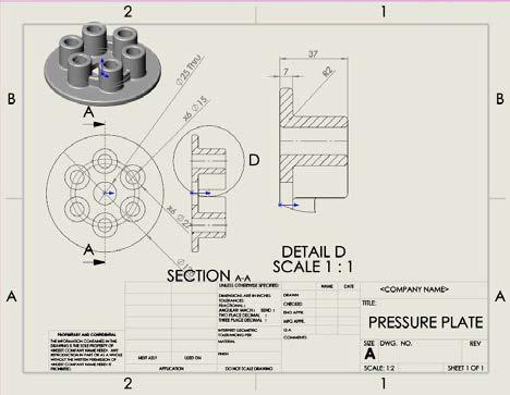
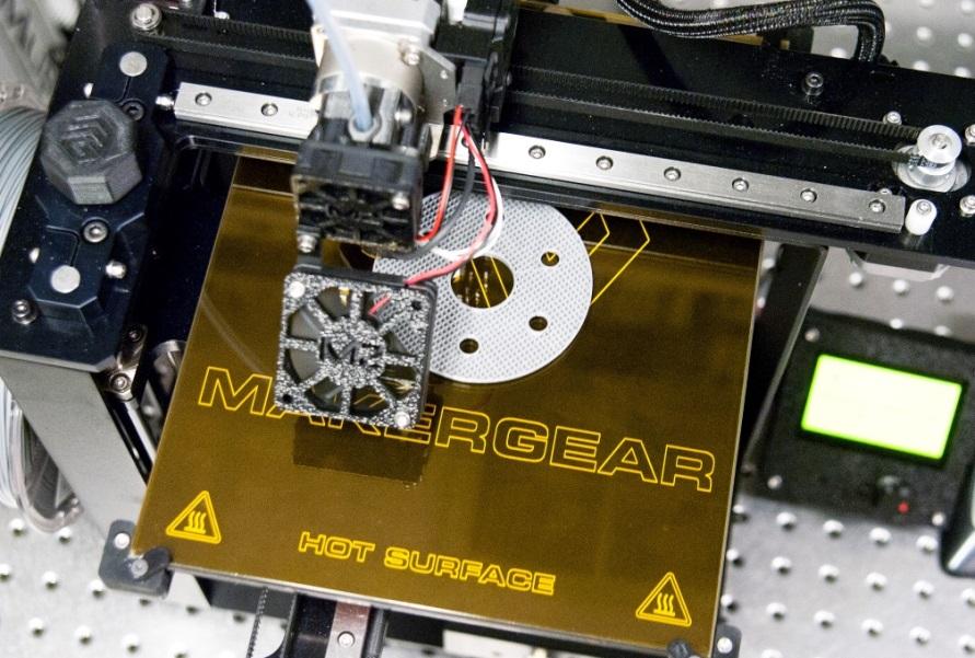
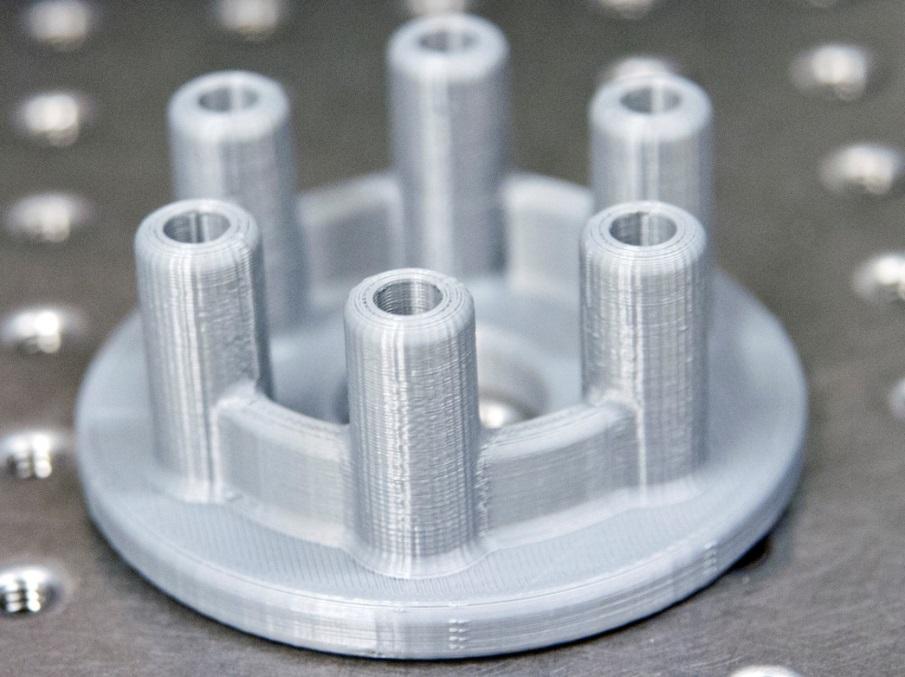
2 1-1-2: 3D Print your SolidWorks part. Page 2


3 Page 3 Exercise 2: Open revolves and Sweeps Objectives: Familiarization with the following: 1. Sketching a revolve profile with lines, arcs, dimensioning, and trimming. 2. Adding dimensional relationships. 3. Creating a revolve. 4. Creating a sweep path and coincidental relationship. 5. Sweeping along the path. 6. Making an extruded-cut with draft. 7. Making a transparent view to see the cuts. 8. Making a Real View appearance : Launch SolidWorks - Select Resources to open the Task Pane, select Tutorials and complete the Revolves and Sweeps tutorial : 3D Print your SolidWorks part.


4 Page 4 Exercise 3: Lofts Objectives: Familiarization with the following: 1. Creating parallel planes. 2. Sketching on specific planes and copying from one plane to another. 3. Lofted bose-base feature and connecting profiles. 4. Flex feature, moving trim planes and bending material Launch SolidWorks - Select Resources to open the Task Pane, select Tutorials and complete the Lofts tutorial : 3D Print your SolidWorks part.


5 Page 5 Exercise 4: Laser Cutting MDF and Acrylic from a SolidWorks File Objectives: Familiarization with the following: 1. Creating a clean SolidWorks top view for laser cutting. 2. Saving SolidWorks drawing as a.dxf file for import into CorelDraw. 3. Preparing the drawing in CorelDRAW for cutting, raster and vector engraving. 4. Operation of the laser cutter, interface software and completion of a part. This exercise can be completed in either the MDC or Anderson Student Innovation Labs. Start with the MDF board, and if all works well redo with the acrylic plastic. Review the following Video Tutorial and Laser Cutter Tutorial for more information. Medical Devices Center Anderson Labs Launch SolidWorks and create a new part. Make a top view-only drawing of a part confined to an 8 square dimension. This is the size of the 1/8 MFD board or acrylic sheet that you will be working with. Include a few cutouts, items to raster etch (etching fills the outline or font), or vector etch (etched outline if no infill). Dimension your part and save. You may create a traditional drawing and save as well. Create a new SolidWorks drawing, selecting no formatting and rename. Drag the top view only of your part into the workspace, and remove any extraneous elements such as crosshairs and centerlines (select each unwanted item and delete). Do not place dimensions on the drawing. Save the drawing, and save an additional file: title.dxf onto a thumb drive Launch CorelDRAW on the computer connected to the laser cutter. Open your file and inspect the drawing. (Select Create a New Document if not importing a SolidWorks file.) Select each object one at a time (or groups) and open the pen by double clicking the icon in the lower right hand corner. Select red and hairline for a cut, blue for raster engraving or black for vector engraving. Save you work on your thumb drive as a CorelDRAW file.


 with the gage:")


 or")

6 Page 6 Check that the vent is on. Place your 8 square x 1/8 th thick stock into the laser cutter upper left hand corner, and focus by setting the Z-height (upper and lower bed) with the gage: When ready to print select Print from the CorelDRAW File menu and in the following dialog select Preferences. The display is different in Anderson Labs vs. the MDC. In Anderson Labs, Select Medium Density Fiberboard (MDF) or Continuous Cast Acrylic depending on the material you are using. Add to the actual material thickness. You may also need


.")
7 Page 7 to increase Vector Cutting from 5-10% if the material is not cutting thru. In the MDC, you must select specific settings from the Laser Cutter Settings Guide available near the printer or under References on the course website. Select Apply and OK for the right then left displays above. Open the laser cutter interface program and you should see your part layout on the 18 x 32 laser bed surface outline. Your part should be positioned in the upper left. Be sure the door is closed and select print from either the software or machine. It will automatically stop when done. If necessary you can stop by opening the door or selecting pause. Check that your cuts went thru before moving the work piece (press on the cut part with your finger). When done clean you workspace, close the door, save your files and close the software. Use the nearby fire extinguisher in the unlikely event that fire occurs. Start Pause


8 Page 8 Exercise 5: Sketch Blocks (Optional) Objectives: Familiarization with the following: 1. Making blocks. 2. Making relationships between blocks. 3. Demonstrating movement. 4. Saving, inserting, editing and renaming blocks. 5. Testing motion about coincident and colinear relationships. 6. Combining blocks as a new block. 7. Linking blocks with relationships Launch SolidWorks - Select Resources to open the Task Pane, select Tutorials and complete the Sketch Blocks tutorial. End of Engineering Drawing, 3D Printing and Laser Cutting
Prof. Steven S. Saliterman Introductory Medical Device Prototyping
 Introductory Medical Device Prototyping Department of Biomedical Engineering, University of Minnesota http://saliterman.umn.edu/ You must complete safety instruction before using tools and equipment in
1/24/2018. Prof. Steven S. Saliterman. Right: Image courtesy of Copper Safety. Prof. Steven S. Saliterman
 Introductory Medical Device Prototyping Department of Biomedical Engineering, University of Minnesota http://saliterman.umn.edu/ You must complete safety instruction before using tools and equipment in
Lesson 10: Loft Features
 10 Goals of This Lesson Your students will be able to create the following part: profiles chisel This lesson plan corresponds to the Loft Features chapter of SolidWorks Getting Started. SolidWorks Student
Toothbrush Holder. A drawing of the sheet metal part will also be created.
 Prerequisite Knowledge Previous knowledge of the following commands is required to complete this lesson; Sketch (Line, Centerline, Circle, Add Relations, Smart Dimension,), Extrude Boss/Base, and Edit
Feature-Based Modeling and Optional Advanced Modeling. ENGR 1182 SolidWorks 05
 Feature-Based Modeling and Optional Advanced Modeling ENGR 1182 SolidWorks 05 Today s Objectives Feature-Based Modeling (comprised of 2 sections as shown below) 1. Breaking it down into features Creating
From the above fig. After sketching the path and profile select the sweep command First select the profile from property manager tree And then select
 Chapter 5 In sweep command there is a) Two sketch profiles b) Two path c) One sketch profile and one path The sweep profile is used to create threads springs circular things and difficult geometry. For
AEROPLANE. Create a New Folder in your chosen location called Aeroplane. The four parts that make up the project will be saved here.
 AEROPLANE Prerequisite Knowledge Previous knowledge of the following commands is required to complete this lesson. Sketching (Line, Rectangle, Arc, Add Relations, Dimensioning), Extrude, Assemblies and
SDC. SolidWorks Tutorial 2001Plus. A Competency Project Based Approach Utilizing 3D Solid Modeling. David C. Planchard & Marie P.
 2001Plus A Competency Project Based Approach Utilizing 3D Solid Modeling David C. Planchard & Marie P. Planchard SDC PUBLICATIONS www.schroff.com www.schroff-europe.com Project 2 Below are the desired
Digital Camera Exercise
 Commands Used New Part This lesson includes Sketching, Extruded Boss/Base, Extruded Cut, Fillet, Chamfer and Text. Click File, New on the standard toolbar. Select Part from the New SolidWorks Document
Create A Mug. Skills Learned. Settings Sketching 3-D Features. Revolve Offset Plane Sweep Fillet Decal* Offset Arc
 Create A Mug Skills Learned Settings Sketching 3-D Features Slice Line Tool Offset Arc Revolve Offset Plane Sweep Fillet Decal* Tutorial: Creating A Custom Mug There are somethings in this world that have
Introduction to Sheet Metal Features SolidWorks 2009
 SolidWorks 2009 Table of Contents Introduction to Sheet Metal Features Base Flange Method Magazine File.. 3 Envelopment & Development of Surfaces.. 14 Development of Transition Pieces.. 23 Conversion to
Tinker Tuesday Project - Fabric Engraving
 Tinker Tuesday Project - Fabric Engraving 1. Open CorelDRAW and create a new document. On the toolbar on the left side of the screen, select the Basic Shapes tool icon. This will allow you to create simple
Introduction to Circular Pattern Flower Pot
 Prerequisite Knowledge Previous knowledge of the sketching commands Line, Circle, Add Relations, Smart Dimension is required to complete this lesson. Previous examples of Revolved Boss/Base, Cut Extrude,
TOY TRUCK. Figure 1. Orthographic projections of project.
 TOY TRUCK Prepared by: Harry Hawkins The following project is of a small, wooden toy truck. This exercise will provide you with the procedure for constructing the various parts of the design then assembling
SolidWorks Part I - Basic Tools SDC. Includes. Parts, Assemblies and Drawings. Paul Tran CSWE, CSWI
 SolidWorks 2015 Part I - Basic Tools Includes CSWA Preparation Material Parts, Assemblies and Drawings Paul Tran CSWE, CSWI SDC PUBLICATIONS Better Textbooks. Lower Prices. www.sdcpublications.com Powered
IT, Sligo. Equations Tutorial
 Equations Tutorial Parametric Modelling: SolidWorks is a parametric modelling system where parameters, such as dimensions and relations, are used to create and control the geometry of the modelled part.
SOLIDWORKS TO LASER CUTTER DOCUMENT CONVERSION
 UNIVERSITY OF CALIFORNIA, SANTA CRUZ BOARD OF STUDIES IN COMPUTER ENGINEERING CMPE118(218)/L: INTRODUCTION TO MECHATRONICS SOLIDWORKS TO LASER CUTTER DOCUMENT CONVERSION PURPOSE: This document outlines
SolidWorks 95 User s Guide
 SolidWorks 95 User s Guide Disclaimer: The following User Guide was extracted from SolidWorks 95 Help files and was not originally distributed in this format. All content 1995, SolidWorks Corporation Contents
LABORATORY MANUAL COMPUTER AIDED DESIGN LAB
 LABORATORY MANUAL COMPUTER AIDED DESIGN LAB Sr. No 1 2 3 Experiment Title Setting up of drawing environment by setting drawing limits, drawing units, naming the drawing, naming layers, setting line types
Assembly Receiver/Hitch/Ball/Pin to use for CAD LAB 5A and 5B:
 MECH 130 CAD LAB 5 SPRING 2017 due Friday, April 21, 2016 at 4:30 PM All of LAB 5 s hardcopies will be working drawing layouts. Do not print out from the part file. We will be using the ME130DRAW drawing
LAB 1A: Intro to SolidWorks: 2D -> 3D Brackets
 LAB 1A: Intro to SolidWorks: 2D -> 3D Brackets Set units Create Sketch Add relations Linear patterns Mirror Fillet Extrude Extrude cut First, set units. click Option on top of main menu Open Document Properties
SolidWize. Online SolidWorks Training. Lofts: Tea Pot
 SolidWize Online SolidWorks Training Lofts: Tea Pot Step 1: Creating the Body Using inches as the unit, create the following sketch on the top plane. We will now add a plane above the top plane so that
Engineering Technology
 Engineering Technology Introduction to Parametric Modelling Engineering Technology 1 See Saw Exercise Part 1 Base Commands used New Part This lesson includes Sketching, Extruded Boss/Base, Hole Wizard,
Essentials of SOLIDWORKS 2015 (4+ Days) * Ve-I Bonus! * File Management + SimulationXpress
 * Ve-I Bonus! * File Management + SimulationXpress") Essentials of SOLIDWORKS 2015 (4+ Days) * Ve-I Bonus! * File Management + SimulationXpress Overview What is SOLIDWORKS? Interface Tour View Manipulation Provides some background info on the SOLIDWORKS
Essentials of SOLIDWORKS 2015 (4+ Days) * Ve-I Bonus! * File Management + SimulationXpress Overview What is SOLIDWORKS? Interface Tour View Manipulation Provides some background info on the SOLIDWORKS
SolidWize. Online SolidWorks Training. Simple Sweep: Head Scratcher
 SolidWize Online SolidWorks Training Simple Sweep: Head Scratcher Step 1: Creating the Handle: Sketch Using Inches as the unit create a sketch on the Front plane. Start with the sketch shown below: Create
Epilog Laser Cutter Moira Gannon Denson, MA Allison Steele, MAT
 Epilog Laser Cutter Moira Gannon Denson, MA Allison Steele, MAT What is It? The Epilog laser cutter uses a high powered laser to make precision cuts in a variety of materials, from paper and wood to acrylic
DEPARTMENT OF MECHANICAL AND INDUSTRIAL ENGINEERING NORTHEASTERN UNIVERSITY
 DEPARTMENT OF MECHANICAL AND INDUSTRIAL ENGINEERING NORTHEASTERN UNIVERSITY CAPSULE PROGRAM Funded by NSF grant #0833636 Tutorial 02 3D Part Modeling SolidWorks 2010 Copyright 2010 Prof. Zeid 3D Part Modeling
Module 2: Radial-Line Sheet-Metal 3D Modeling and 2D Pattern Development: Right Cone (Regular, Frustum, and Truncated)
") Inventor (5) Module 2: 2-1 Module 2: Radial-Line Sheet-Metal 3D Modeling and 2D Pattern Development: Right Cone (Regular, Frustum, and Truncated) In this tutorial, we will learn how to build a 3D model
Inventor (5) Module 2: 2-1 Module 2: Radial-Line Sheet-Metal 3D Modeling and 2D Pattern Development: Right Cone (Regular, Frustum, and Truncated) In this tutorial, we will learn how to build a 3D model
Autodesk Inventor. In Engineering Design & Drafting. By Edward Locke
 Autodesk Inventor In Engineering Design & Drafting By Edward Locke Engineering Design Drafting Essentials Working Drawings: Orthographic Projection Views (multi-view, auxiliary view, details and sections)
Introducing SolidWorks
 Introducing SolidWorks SAAST Robotics 2008 SolidWorks Software Visually-based 3-D Mechanical design software Engineers and Designers use it to: Quickly sketch out ideas Experiment with features, dimensions
Inventor Activity 5: Lofted Vase
 Inventor Activity 5: Lofted Vase In this tutorial, you will use a few new commands to create a free form Lofted object. Sometimes you want to create an object that is not made up of square, flat, or perfectly
Model House Exercise-( Extrude)
") -( Extrude) Prerequisite knowledge Focus of the lesson Commands Used This lesson requires an understanding of using the sketch commands including Inserting a new sketch Adding sketch geometry Understanding
-( Extrude) Prerequisite knowledge Focus of the lesson Commands Used This lesson requires an understanding of using the sketch commands including Inserting a new sketch Adding sketch geometry Understanding
< Then click on this icon on the vertical tool bar that pops up on the left side.
 Pipe Cavity Tutorial Introduction The CADMAX Solid Master Tutorial is a great way to learn about the benefits of feature-based parametric solid modeling with CADMAX. We have assembled several typical parts
Alibre Design Tutorial - Simple Extrude Step-Pyramid-1
 Alibre Design Tutorial - Simple Extrude Step-Pyramid-1 Part Tutorial Exercise 4: Step-Pyramid-1 [text version] In this Exercise, We will set System Parameters first. Then, in sketch mode, outline the Step
Introduction to Autodesk Inventor for F1 in Schools (Australian Version)
") Introduction to Autodesk Inventor for F1 in Schools (Australian Version) F1 in Schools race car In this course you will be introduced to Autodesk Inventor, which is the centerpiece of Autodesk s Digital
Introduction to Autodesk Inventor for F1 in Schools (Australian Version) F1 in Schools race car In this course you will be introduced to Autodesk Inventor, which is the centerpiece of Autodesk s Digital
Product Modelling in Solid Works
 Product Modelling in Solid Works In the following exercise you will use solid works to construct the computer mouse shown opposite. In this exercise you will use a number of advanced features to achieve
Shaft Hanger - SolidWorks
 ME-430 INTRODUCTION TO COMPUTER AIDED DESIGN Shaft Hanger - SolidWorks BY: DR. HERLI SURJANHATA ASSIGNMENT Submit TWO isometric views of the Shaft Hanger with your report, 1. Shaded view of the trimetric
Copyrighted. Material. Copyrighted. Material. Copyrighted. Material. Copyrighted. Material
 ENGINEERING & COMPUTER GRAPHICS WORKBOOK Using SolidWorks 2008 Ronald E. Barr Thomas J. Krueger Theodore A. Aanstoos Davor Juricic SDC PUBLICATIONS Schroff Development Corporation www.schroff.com Better
1. Open the Feature Modeling demo part file on the EEIC website. Ask student about which constraints needed to Fully Define.
 BLUE boxed notes are intended as aids to the lecturer RED boxed notes are comments that the lecturer could make Control + Click HERE to view enlarged IMAGE and Construction Strategy he following set of
Tinker Tuesday Project - Wood Book Covers
 Tinker Tuesday Project - Wood Book Covers 1. On the laser engraver computer, click on the folder icon on the task bar. Then, select Thaw Space and open the document titled Living Hinge Template. 2. Measure
SolidWorks Design & Technology
 SolidWorks Design & Technology Training Course at PHSG Ex 5. Lego man Working with part files 8mm At first glance the Lego man looks complicated but I hope you will see that if you approach a project one
Beginner s Guide to SolidWorks Alejandro Reyes, MSME Certified SolidWorks Professional and Instructor SDC PUBLICATIONS
 Beginner s Guide to SolidWorks 2008 Alejandro Reyes, MSME Certified SolidWorks Professional and Instructor SDC PUBLICATIONS Schroff Development Corporation www.schroff.com www.schroff-europe.com Part Modeling
Engineering & Computer Graphics Workbook Using SolidWorks 2014
 Engineering & Computer Graphics Workbook Using SolidWorks 2014 Ronald E. Barr Thomas J. Krueger Davor Juricic SDC PUBLICATIONS Better Textbooks. Lower Prices. www.sdcpublications.com Powered by TCPDF (www.tcpdf.org)
for Solidworks TRAINING GUIDE LESSON-9-CAD
 for Solidworks TRAINING GUIDE LESSON-9-CAD Mastercam for SolidWorks Training Guide Objectives You will create the geometry for SolidWorks-Lesson-9 using SolidWorks 3D CAD software. You will be working
SolidWorks 2013 Part I - Basic Tools
 SolidWorks 2013 Part I - Basic Tools Parts, Assemblies and Drawings Paul Tran CSWE, CSWI Supplemental Files SDC PUBLICATIONS Schroff Development Corporation Better Textbooks. Lower Prices. www.sdcpublications.com
Engineering & Computer Graphics Workbook Using SOLIDWORKS
 Engineering & Computer Graphics Workbook Using SOLIDWORKS 2017 Ronald E. Barr Thomas J. Krueger Davor Juricic SDC PUBLICATIONS Better Textbooks. Lower Prices. www.sdcpublications.com Powered by TCPDF (www.tcpdf.org)
Clock Exercise (Inserting Planes)
") Clock Exercise (Inserting Planes) Prerequisite Knowledge To complete this exercise you will need to be familiar with Sketching, Applying relations, Extrude Boss/ Base, Extrude cut, Applying Textures, Renaming
Clock Exercise (Inserting Planes) Prerequisite Knowledge To complete this exercise you will need to be familiar with Sketching, Applying relations, Extrude Boss/ Base, Extrude cut, Applying Textures, Renaming
Wireless Mouse Surfaces
 Wireless Mouse Surfaces Design & Communication Graphics Table of Contents Table of Contents... 1 Introduction 2 Mouse Body. 3 Edge Cut.12 Centre Cut....14 Wheel Opening.. 15 Wheel Location.. 16 Laser..
Alibre Design Tutorial: Loft, Extrude, & Revolve Cut Loft-Tube-1
 Alibre Design Tutorial: Loft, Extrude, & Revolve Cut Loft-Tube-1 Part Tutorial Exercise 5: Loft-Tube-1 [Complete] In this Exercise, We will set System Parameters first, then part options. Then, in sketch
Foreword. If you have any questions about these tutorials, drop your mail to
 Foreword The main objective of these tutorials is to give you a kick start using Solidworks. The approach to write this tutorial is based on what is the most important knowledge you should know and what
10/14/2010. Chevy Malibu. Vehicle Design with Solidworks. Start SolidWorks Create a New SolidWorks Document. Miles, Rowardo B
 Chevy Malibu Vehicle Design with Solidworks Start SolidWorks Create a New SolidWorks Document Miles, Rowardo B 1 Click: Part and then OK Now you are ready to make a Part. 2 Right Toolbar: Document Properties:
Cube in a cube Fusion 360 tutorial
 Cube in a cube Fusion 360 tutorial n Before using these instructions, it is helpful to watch this video screencast of the CAD drawing actually being done in the software. Click to link to the video tutorial.
J. La Favre Fusion 360 Lesson 5 April 24, 2017
 In this lesson, you will create a funnel like the one in the illustration to the left. The main purpose of this lesson is to introduce you to the use of the Revolve tool. The Revolve tool is similar to
Lesson 6 2D Sketch Panel Tools
 Lesson 6 2D Sketch Panel Tools Inventor s Sketch Tool Bar contains tools for creating the basic geometry to create features and parts. On the surface, the Geometry tools look fairly standard: line, circle,
Engineering Design with SolidWorks A Step-by-Step Project Based Approach Utilizing 3D Solid Modeling. David C. Planchard & Marie P.
 Engineering Design with SolidWorks 2003 A Step-by-Step Project Based Approach Utilizing 3D Solid Modeling David C. Planchard & Marie P. Planchard SDC PUBLICATIONS www.schroff.com www.schroff-europe.com
SolidWorks Navigation
 SolidWorks Basics SolidWorks Navigation Command Bar Feature Tree Model Window Simple Box Select the Front plane Create a new sketch Create a Center Rectangle from the origin Smart Dimension the length
Nut and Bolt Tutorial
 Thread Representations Nut and Bolt Tutorial Parts to a Thread Thread Dimensioning Major Diameter Thread Series (IE UNC, UNF, ACME, etc) ½ - 13 UNC 2 A or B A = External B = Internal Threads per Inch Class
Student + Instructor:
 BLUE boxed notes are intended as aids to the lecturer RED boxed notes are comments that the lecturer could make Show 01 Solid Modeling Intro slides quickly. SolidWorks Layout slides are on EEIC for reference
Using Siemens NX 11 Software. The connecting rod
 Using Siemens NX 11 Software The connecting rod Based on a Catia tutorial written by Loïc Stefanski. At the end of this manual, you should obtain the following part: 1 Introduction. Start NX 11 and open
Drawing and Assembling
 Youth Explore Trades Skills Description In this activity the six sides of a die will be drawn and then assembled together. The intent is to understand how constraints are used to lock individual parts
Intro to CO 2 Laser Cutting
 MAKERSPACE Intro to CO 2 Laser Cutting What Can I Do With the CO 2 Laser? CO 2 laser cutters and engravers are excellent for making precise 2-dimensional cuts in a variety of materials, as well as engraving
Getting Started. Before You Begin, make sure you customized the following settings:
 Getting Started Getting Started Before getting into the detailed instructions for using Generative Drafting, the following tutorial aims at giving you a feel of what you can do with the product. It provides
SolidWorks 2014 Part I - Basic Tools
 SolidWorks 2014 Part I - Basic Tools Parts, Assemblies and Drawings Paul Tran CSWE, CSWI SDC PUBLICATIONS Better Textbooks. Lower Prices. www.sdcpublications.com Powered by TCPDF (www.tcpdf.org) Visit
Modeling Basic Mechanical Components #1 Tie-Wrap Clip
 Modeling Basic Mechanical Components #1 Tie-Wrap Clip This tutorial is about modeling simple and basic mechanical components with 3D Mechanical CAD programs, specifically one called Alibre Xpress, a freely
Creo Revolve Tutorial
 Creo Revolve Tutorial Setup 1. Open Creo Parametric Note: Refer back to the Creo Extrude Tutorial for references and screen shots of the Creo layout 2. Set Working Directory a. From the Model Tree navigate
The Revolve Feature and Assembly Modeling
 The Revolve Feature and Assembly Modeling PTC Clock Page 52 PTC Contents Introduction... 54 The Revolve Feature... 55 Creating a revolved feature...57 Creating face details... 58 Using Text... 61 Assembling
Spatula. Spatula SW 2015 Design & Communication Graphics Page 1
 Spatula Introduction: The model shown in the picture is made of three parts, - the base, the washer and the handle. The base requires the use of Spline and Style Spline command, Slot command and Mirror
Below are the desired outcomes and usage competencies based on the completion of Project 4.
 Engineering Design with SolidWorks Project 4 Below are the desired outcomes and usage competencies based on the completion of Project 4. Project Desired Outcomes: An understanding of the customer s requirements
Starting a 3D Modeling Part File
 1 How to Create a 3D Model and Corresponding 2D Drawing with Dimensions, GDT (Geometric Dimensioning and Tolerance) Symbols and Title Block in SolidWorks 2013-2014 By Edward Locke This tutorial will introduce
Introduction to 3D Printing. Activity 1: Design a keychain using computer-aided design software
 Introduction to 3D Printing Activity 1: Design a keychain using computer-aided design software 1 In this activity we ll design a keychain name tag and learn the fundamentals of computer-aided design, the
Engineering Design. with SolidWorks A Step-by-Step Project Based Approach Utilizing 3D Solid Modeling
 INSIDE: MultiMedia CD An audio/visual presentation of the tutorial projects Engineering Design with SolidWorks 2010 A Step-by-Step Project Based Approach Utilizing 3D Solid Modeling Introductory Level
Module 1G: Creating a Circle-Based Cylindrical Sheet-metal Lateral Piece with an Overlaying Lateral Edge Seam And Dove-Tail Seams on the Top Edge
 Inventor (10) Module 1G: 1G- 1 Module 1G: Creating a Circle-Based Cylindrical Sheet-metal Lateral Piece with an Overlaying Lateral Edge Seam And Dove-Tail Seams on the Top Edge In Module 1A, we have explored
Veerapandian.K Mechanical Engg Vedharanyam A manual to mechanical designers How Solid works Works?
 Compiled by Veerapandian.K Mechanical Engg Vedharanyam-614 810 A manual to mechanical designers How Solid works Works? Solid works Overview Solid works main idea is user to create drawing directly in 3D
and Engineering Graphics
 SOLIDWORKS 2018 and Engineering Graphics An Integrated Approach Randy H. Shih SDC PUBLICATIONS Better Textbooks. Lower Prices. www.sdcpublications.com Powered by TCPDF (www.tcpdf.org) Visit the following
Creo Parametric 4.0 Basic Design
 Creo Parametric 4.0 Basic Design Contents Table of Contents Introduction...1 Objective of This Textbook...1 Textbook Outline...2 Textbook Conventions...3 Exercise Files...3 System Configuration...4 Notes
Copyright by J.W. Zuyderduyn Page 1
 Copyright by J.W. Zuyderduyn www.learnsolidworks.com Page 1 A step by step SolidWorks Tutorial Copyright by J.W. Zuyderduyn www.learnsolidworks.com Page 2 About the Author Hi, my name is Jan-Willem Zuyderduyn
Part 8: The Front Cover
 Part 8: The Front Cover 4 Earpiece cuts and housing Lens cut and housing Microphone cut and housing The front cover is similar to the back cover in that it is a shelled protrusion with screw posts extruding
Copyrighted. Material. Copyrighted. Material. Copyrighted. Material. Copyrighted. Material
 ENGINEERING & COMPUTER GRAPHICS WORKBOOK Using SolidWorks 2005 Ronald E. Barr Thomas J. Krueger Theodore A. Aanstoos Davor Juricic SDC PUBLICATIONS Schroff Development Corporation www.schroff.com www.schroff-europe.com
Introduction to Revolve - A Glass
 Introduction to Revolve - A Glass Design & Communication Graphics 1 Object Analysis sheet Design & Communication Graphics 2 Prerequisite Knowledge Previous knowledge of the following commands are required
Lab 3 Introduction to SolidWorks I Silas Bernardoni 10/9/2008
 1 Introduction This lab is designed to provide you with basic skills when using the 3D modeling program SolidWorks. You will learn how to build parts, assemblies and drawings. You will be given a physical
Sash Clamp. Sash Clamp SW 2015 Design & Communication Graphics Page 1.
 Sash Clamp 1 Introduction: The Sash clamp consists of nine parts. In creating the clamp we will be looking at the improvements made by SolidWorks in linear patterns, adding threads and in assembling the
Purlin Roof. Create a New Folder in your chosen location called Purlin Roof. The nine parts that make up the project will be saved here.
 Purlin Roof Prerequisite Knowledge Previous knowledge of the following commands is required to complete this lesson. Sketching (Line, Rectangle, Add Relations, Dimensioning), Inserting Planes, Extrude,
Using Siemens NX 11 Software. Sheet Metal Design - Casing
 Using Siemens NX 11 Software Sheet Metal Design - Casing Based on a YouTube NX tutorial 1. 1 https://www.youtube.com/watch?v=-siyi1vz87k A&M CAD in mechanical engineering 1 1 Introduction. Start NX 11
DUE DATE: Friday 4/6/2018 at 3:30 PM
 MECH 130 SPRING 2018 CAD LAB 4 FINAL REVISION HARDCOPIES NEEDED DUE DATE: Friday 4/6/2018 at 3:30 PM After the revised hitch, the ball and the pin parts were created from the Handout call LAB4 PART Creation,
Autodesk Inventor Module 17 Angles
 Inventor Self-paced ecourse Autodesk Inventor Module 17 Angles Learning Outcomes When you have completed this module, you will be able to: 1 Describe drawing inclined lines, aligned and angular dimensions,
Tinker Tuesday Project - Pumpkin Carving
 Tinker Tuesday Project - Pumpkin Carving 1. Acquire a small pumpkin (between six and seven inches tall excluding the stem). A full size pumpkin will not fit in the engraver. 2. Use a knife to remove the
SolidWorks Reference Geometry
 SolidWorks Reference Geometry IDeATe Laser Micro Part 2 Dave Touretzky and Susan Finger 1. Symmetry and Reference Geometry Today, you ll make this part bear-like face and then cut it on the laser cutter:
Rotational Patterns of Sketched Features Using Datum Planes On-The-Fly
 Rotational Patterns of Sketched Features Using Datum Planes On-The-Fly Patterning a sketched feature (such as a slot, rib, square, etc.,) requires a slightly different technique. Why can t we create a
SolidWorks Part I - Basic Tools SDC. Includes. Parts, Assemblies and Drawings. Paul Tran CSWE, CSWI
 SolidWorks 2015 Part I - Basic Tools Includes CSWA Preparation Material Parts, Assemblies and Drawings Paul Tran CSWE, CSWI SDC PUBLICATIONS Better Textbooks. Lower Prices. www.sdcpublications.com Powered
Principles and Practice
 Principles and Practice An Integrated Approach to Engineering Graphics and AutoCAD 2011 Randy H. Shih Oregon Institute of Technology SDC PUBLICATIONS www.sdcpublications.com Schroff Development Corporation
Solidworks tutorial. 3d sketch project. A u t h o r : M. G h a s e m i. C o n t a c t u s : i n f s o l i d w o r k s a d v i s o r.
 Solidworks tutorial 3d sketch project A u t h o r : M. G h a s e m i C o n t a c t u s : i n f o @ s o l i d w o r k s a d v i s o r. c o m we will create this frame during the tutorial : In this tutorial
CAD/CAM Lamp Project using 2D Design and the X-660 Laser Cutter
 CAD/CAM Lamp Project using 2D Design and the X-660 Laser Cutter Paul Tate 2008 Booklet Version 2 Getting Started the preliminaries The Laser cutter which is going to cut out your acrylic bases and polypropylene
Lesson 6: Drawing Basics
 6 Lesson 6: Drawing Basics Goals of This Lesson Understand basic drawing concepts. Create detailed drawings of parts and assemblies:. Before Beginning This Lesson Create Tutor1 and Tutor2 parts and the
EXERCISE ONE: BEACH BUGGY.
 EXERCISE ONE: BEACH BUGGY. Prerequisite knowledge Students should have completed Exercises from the file: Introduction to Assemblies Concept Mates Focus of lesson Commands Used This lesson will focus on
When you complete this assignment you will:
 Objjectiives When you complete this assignment you will: 1. sketch and create models using new work planes and the loft command. 2. sketch and create models using the revolve command. 3. sketch and dimension
Introduction to 3D CAD with SolidWorks. Jianan Li
 Introduction to 3D CAD with SolidWorks Jianan Li Create a New Part The first time you launch SolidWorks, it asks you to set the default units and dimension standard. Make sure you have IPS and ANSI selected,