Foreword. If you have any questions about these tutorials, drop your mail to
|
|
|
- Lynn Kennedy
- 6 years ago
- Views:
Transcription
1
2 Foreword The main objective of these tutorials is to give you a kick start using Solidworks. The approach to write this tutorial is based on what is the most important knowledge you should know and what is commonly tool used. You will learn step by step working on it. These tutorials will teach you the basic skills of using Solidworks in your daily design works. Even this tutorials didn t have full explanations of tools that Solidworks have but don t worry you will along the way, as I did. If you have any questions about these tutorials, drop your mail to support@solidworkstutorials.com Solidworks 2008 / 2009 Tutorials : Beginner solidworkstutorials.com, All rights reserved. This publication is copyright under the solidworkstutorials.com All rights reserved. Apart from any fair dealing for the purpose of private study, research, criticism, or review, as permitted under the Copyright Designs and Patents Act 1988, no part may be reproduced, stored in a retrieval system, or transmitted in any form or by any means, electronic, electrical, chemical, mechanical, photocopying, recording or otherwise, without the prior permission of the copyright owners. Unlicensed multiple copying of this publication is illegal. Inquiries should be addressed to: support@solidworkstutorials.com If this guide is distributed with software that includes an end-user agreement, this guide, as well as the software described in it, is furnished under license and may be used or copied only in accordance with the terms of such license. Except as permitted by any such license, no part of this guide may be reproduced, stored in a retrieval system, or transmitted, in any form or by any means, electronic, mechanical, recording, or otherwise, without the prior written permission of solidworkstutorials.com. Please note that the content in this guide is protected under copyright law even if it is not distributed with software that includes an end-user license agreement. The content of this guide is furnished for informational use only, is subject to change without notice, and should not be construed as a commitment by solidworkstutorials.com. Solidworkstutorials.com assumes no responsibility or liability for any errors or inaccuracies that may appear in the informational content contained in this guide. Please remember that existing artwork or images that you may want to include in your project may be protected under copyright law. The unauthorized incorporation of such material into your new work could be a violation of the rights of the copyright owner. Please be sure to obtain any permission required from the copyright owner. Any references to company names in sample templates are for demonstration purposes only and are not intended to refer to any actual organization. The publishers are not responsible for any statement made in this publication. Data, discussion, and conclusions developed by the Author are for information only and are not intended for use without independent substantiating investigation on the part of the potential users. Opinions expressed are those of the Author and are not necessarily those of the Institution of Mechanical Engineers or its publishers. i
3 Solidworks Tutorials: Beginner Table of contents Table of contents Beginner Part 1: My First Solid 1 The big picture how SolidWorks works, it starts with a simple editable sketch. From this sketch a feature build the solid. From this solid it produces drawing... Beginner Part 2: Sketching 10 Sketch is the base of your part, it s a good practice to master sketching in SolidWorks... Beginner Part 3: Turning Parts 27 Some parts such as pins and shafts can be manufacture by turning process on lathe machine, we can create turning part by revolving it sketch on it axis... Beginner Part 4: Hole Wizard 32 Hole Wizard is used for creating predefined and standard holes such as counter bore hole, counter sunk hole, screw clearance hole and many more... Beginner Part 5: Pattern 41 Pattern (or some called array) is used to repeat features in linear arrangement or circular arrangement. It s good to know how to optimize these tool, it help you make your part faster and easier... Beginner Part 6: Assembly Parts 52 Assembly is a part of design process, it show how all designed parts work together as a single unit... Beginner Part 7: Detailing Drawing 82 Once solid parts created we need to transfer it to engineering drawing so the others can understand your parts Solidworks Tutorials: Beginner Table of contents ii

4 Beginner Part 1: My First Solid Beginner Part 1: My First Solid The big picture how SolidWorks works, it starts with a simple editable sketch. From this sketch a features build the solid. From this solid it produces drawing... Let s begin your first solid Click New, click Part, OK. 2. Click Front Plane, insert sketch on plane by click Sketch. In this tutorial you will make this bracket, start from sketch and build features. 3. Click Sketch, click Corner Rectangular. Start first point at origin and click another point at top right side. 4. Click Smart Dimension, click top edge set dimension to 3in and click right edge set dimension to 2in. Beginner Part 1: My First Solid 1


5 Beginner Part 1: My First Solid 5. To build features, click Features>Extruded Boss/Base, set D1 to 0.10in and. Beginner Part 1: My First Solid 2

6 Beginner Part 1: My First Solid 6. Click on front face of the part, click Normal To. 7. Click Sketch>Circle, sketch circle on face. Click Smart Dimension, click circle edge and set diameter to 0.6in. For circle positioning click circle edge and vertical part edge set to 0.5in. Click circle edge again and click horizontal part edge set to 0.5in. Beginner Part 1: My First Solid 3
7 Beginner Part 1: My First Solid 8. Click Features>Extruded Cut, Direction 1 to Through All change and. Beginner Part 1: My First Solid 4

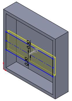
8 Beginner Part 1: My First Solid 9. Click on front face and click Sketch. Select Corner Rectangular sketch rectangular from top right corner edge to center. 10. Click Smart Dimension, set rectangular dimension, click on top rectangle edge and set to 2in and click on right rectangle edge and set to 1in. Beginner Part 1: My First Solid 5

9 Beginner Part 1: My First Solid Click Features>Extruded Cut and select Through All 11. Click on front face and select Sketch and.. Click Corner Rectangular and sketch rectangular start from bottom left edge to right edge. Beginner Part 1: My First Solid 6


10 Beginner Part 1: My First Solid Click Smart Dimension and set rectangular height to 0.1in. 12. Click Features>Extruded Boss/Base set Direction 1 to 0.5in and. Click Display Style and select Isometric. Beginner Part 1: My First Solid 7


11 Beginner Part 1: My First Solid 13. Click Fillet, set fillet radius to 0.1in check Full preview add fillet to all edges Beginner Part 1: My First Solid 8

12 Beginner Part 1: My First Solid and. 14. Save the part as Bracket and you re done! Simple isn t it? Go to table of contents Go to beginning of chapter tutorial Go to Beginner Part 1: My First Solid 9

13 Beginner Part 2: Sketching Beginner Part 2: Sketching Sketch is the base of your part, it s a good practice to master sketching in SolidWorks Click New, click Part, OK. 2. Click Front Plane, insert sketch on plane by click Sketch. In this tutorial you will make this box, start from sketch and build features. You ll learn how to use sketch tools to build this part. 3. Click Sketch, click Corner Rectangular. Start first point at origin and click another point at top right side. 4. Click Smart Dimension, click bottom edge set dimension to 2in and click right edge set dimension to 2in. Beginner Part 2: Sketching 10

14 Beginner Part 2: Sketching 5. To build features, click Features>Extruded Boss/Base, set D1 to 0.50in and. Beginner Part 2: Sketching 11


15 Beginner Part 2: Sketching 6. Click on front face of the part, click Normal To. 7. Click on front face and click Sketch. Beginner Part 2: Sketching 12


16 Beginner Part 2: Sketching 8. Click Offset Entities, set to 0.1in and check Reverse box and. 9. Click Extruded Cut, change D1 to 0.4in. Beginner Part 2: Sketching 13

17 Beginner Part 2: Sketching 10. Click on side face, click Sketch. 11. While pressing Ctrl key select inner left and right edge. Click Convert Entities. 12. Select Centerline from line menu, sketch a centerline midpoint to midpoint of both converted edges. Press Esc to end centerline tool. Beginner Part 2: Sketching 14
18 Beginner Part 2: Sketching 13. Click sketched centerline and click Offset Entities. Beginner Part 2: Sketching 15

19 Beginner Part 2: Sketching Set Parameter, D to 0.3in check Bi-directional and. 14. Now click Trim Entities to remove excess line, before make any cut make sure under option Trim to closest is selected. Trim extra line as below sketch. Answers Yes if notification appear. Beginner Part 2: Sketching 16

 and set D1 to 0.")
20 Beginner Part 2: Sketching 15. Click View Orientation>Isometric. 16. Click Features>Extruded Boss/Base, for Direction 1, click Reverse Direction (green box) and set D1 to 0.1in. Beginner Part 2: Sketching 17

21 Beginner Part 2: Sketching and. Beginner Part 2: Sketching 18


22 Beginner Part 2: Sketching 17. Click on front face and click Normal To. 18. Click on front face and click Sketch. Beginner Part 2: Sketching 19


23 Beginner Part 2: Sketching 19. Click Circle, sketch circle at left edge. 20. Click Smart Dimension, click on circle and set it diameter to 0.15in. Click on circle edge and left edge and set distance to 0.2in. Click on circle edge and click on inner bottom edge and set distance to 0.15in. Press Esc to end Smart Dimension tool. Beginner Part 2: Sketching 20


24 Beginner Part 2: Sketching 21. Click on sketched circle, click Copy Entities. Set delta x to 0.3in and. 22. Click Centerline, sketch centerline across front face and make sure it starts at midpoint left edge and midpoint right edge and. Press Esc to end centerline Beginner Part 2: Sketching 21

25 Beginner Part 2: Sketching tool. 23. While press Ctrl key, select both sketched circle and click Mirror Entities, on Mirror Option click Mirror about: box, (so is highlighted to blue color) and select centerline and. Beginner Part 2: Sketching 22


26 Beginner Part 2: Sketching 24. Click Features>Extruded Cut, and set D1 to 0.1in 25. Click View Orientation>Back, and. and click on back face and click Sketch. 26. Click Sketch>Circle, sketch circle at lower left edge. Click Smart Dimension and dimension sketched circle as Beginner Part 2: Sketching 23


27 Beginner Part 2: Sketching sketch below. and. 27. Click on sketched circle, and click Linear Sketch Pattern and on Direction 1 set D1 to 1.2in and on Direction 2, change # to 2 and set D2 to 1.2in and. Beginner Part 2: Sketching 24


28 Beginner Part 2: Sketching 28. Click Features>Extruded Cut, and set direction to Through All and. Click View Orientation>Isometric. Beginner Part 2: Sketching 25
29 Beginner Part 2: Sketching 29. Save the part as Sketch and you re done! Simple isn t it? Go to table of contents Go to beginning of chapter tutorial Go to Beginner Part 2: Sketching 26
30 Beginner Part 3: Turning Part Beginner Part 3: Turning Part Some parts such as pins and shafts can be manufacture by turning process on lathe machine, we can create turning part by revolving it sketch on it axis Click New, click Part, OK. In this tutorial you will make this pin, start from sketch and build solid body by revolve it sketch on axis. You ll learn how to use revolved boss/base and revolved cut to build this part. 2. Click Front Plane, insert sketch on plane by click Sketch. 3. Click on Line, sketch a closed loop start at origin, sketch as sketched below end back at origin. and 4. Click Smart Dimension and dimension sketch as sketched below. and. 5. Click Features>Revolved Boss/Base, and click on bottom line as it axis. Beginner Part 3: Turning Part 27


31 Beginner Part 3: Turning Part 6. and. 7. Click View Orientation>Front and click Front Plane and click Sketch. Beginner Part 3: Turning Part 28


32 Beginner Part 3: Turning Part 8. Click Corner Rectangle, and sketch rectangle overlap on solid body as sketched below. and. 9. Click Smart Dimension and dimension sketch as sketched below. 10. To view solid body axis, click View>Temporary Axes. 11. To make second undercut, click Features>Revolved Cut and select temporary axes as it axis Beginner Part 3: Turning Part 29


33 Beginner Part 3: Turning Part and. Beginner Part 3: Turning Part 30
34 Beginner Part 3: Turning Part 12. To hide temporary axes, click View>Temporary Axes. 13. Save the part and you re done! Simple isn t it? Go to table of contents Go to beginning of chapter tutorial Go to Beginner Part 3: Turning Part 31
35 Beginner Part 4: Hole Wizard Beginner Part 4: Hole Wizard Hole Wizard is used for creating predefined and standard holes such as counter bore hole, counter sunk hole, screw clearance hole and many more Click New, click Part, OK. In this tutorial you will add counterbore, countersink and tap holes to this plate by using Hole Wizard tools. 2. Click Top Plane, insert sketch on plane by click Sketch. 3. Click on Corner Rectangle, sketch a rectangle start at origin. and. 4. Click Smart Dimension and dimension sketch as sketch below. and. 5. Click Features>Extruded Boss/Base, on Direction 1 set D1 to 1in Beginner Part 4: Hole Wizard 32
36 Beginner Part 4: Hole Wizard and. 6. Click on top face and click Normal To. 7. Click Features>Hole Wizard on Hole Type, select Counterbore, Standard to Ansi Inch, Type to Socket Head Cap Screw, Size to #10, Fit to Normal and End Condition to Through All. Beginner Part 4: Hole Wizard 33
37 Beginner Part 4: Hole Wizard For positions placement for this counterbore hole, click on Positions tab. more positions at each edge. Now click three Beginner Part 4: Hole Wizard 34

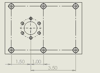
38 Beginner Part 4: Hole Wizard 8. Click on Smart Dimensions, click on center point of counterbore hole and click left edge, set dimension to 0.5in. Continue dimensioning as sketched below. and. 9. For adding countersink at center, click on top face and click on Hole Wizard. Beginner Part 4: Hole Wizard 35

39 Beginner Part 4: Hole Wizard On Hole Type, select Countersink, Standard to Ansi Inch, Type to Flat Head Screw (100), Size to #10, Fit to Normal and End Condition to Through All. 10. For positions placement for this countersink holes, click on Positions tab. more positions at center. Now click three Beginner Part 4: Hole Wizard 36
40 Beginner Part 4: Hole Wizard 11. Click on Smart Dimensions, click on center point of countersink hole and click left edge, set dimension to 2.5in. Continue dimensioning as sketched below. and. 12. For adding center tap hole, click on top face at center and click Hole Wizard. Beginner Part 4: Hole Wizard 37

41 Beginner Part 4: Hole Wizard On Hole Type, select Tap, Standard to Ansi Inch, Type to Tapped hole, Size to 1/2-13, End Condition to Through All. 13. For positions placement for this tap hole, click on Positions tab. There is another style to positions hole wizard is define it position by sketch, let try it. Click on Centerline, Sketch a horizontal line start at midpoint of left edge to midpoint left Beginner Part 4: Hole Wizard 38

42 Beginner Part 4: Hole Wizard edge. Press Esc to end sketch centerline. 14. Click and drag tap center to midpoint of centerline. and. 15. Click View Orientation>Isometric. Done. Beginner Part 4: Hole Wizard 39
43 Beginner Part 4: Hole Wizard 16. Save the part as Plate1 and you re done! Simple isn t it? Go to table of contents Go to beginning of chapter tutorial Go to Beginner Part 4: Hole Wizard 40
44 Beginner Part 5: Pattern Beginner Part 5: Pattern Pattern (or some called array) is used to repeat features in linear arrangement or circular arrangement. It s good to know how to optimize these tool, it help you make your part faster and easier Click New, click Part, OK. In this tutorial you will add multiple features as linear pattern and circular pattern using pattern tools. 2. Click Top Plane, insert sketch on plane by click Sketch. 3. Click on Corner Rectangle, sketch a rectangle start at origin. and. 4. Click Smart Dimension and dimension sketch as sketch below. and. 5. Click Features>Extruded Boss/Base, on Direction 1 set D1 to 1in Beginner Part 5: Pattern 41

45 Beginner Part 5: Pattern and. 6. Click on top face and click Normal To. 7. Click on top face and click Sketch. Beginner Part 5: Pattern 42

46 Beginner Part 5: Pattern Click on Circle and sketch a circle on top face and. 8. Click on Smart Dimension and dimension sketched circle as sketch below. 9. Click Features>Extruded Cut on Direction 1 set to Through All. and. 10. Click Features>Hole Wizard on Hole Type, select Counterbore, Standard to Ansi Inch, Type to Socket Head Cap Screw, Size to #10, Fit to Normal and End Condition to Through All. Beginner Part 5: Pattern 43

47 Beginner Part 5: Pattern For positions placement for this counterbore hole, click on Positions tab. at lower left edge. Click one point Beginner Part 5: Pattern 44
48 Beginner Part 5: Pattern 11. Click on Smart Dimension and dimension sketched circle as sketch below. and. 12. To pattern this counterbore hole, click on CBORE for #10 Socket Head Cap Screw1 and click Linear Pattern. Click on bottom edge as Direction 1 pattern. Beginner Part 5: Pattern 45


49 Beginner Part 5: Pattern Set D1 to 2.5in and pattern # to 3. Click on highlighted arrow to switch it directions. 13. Click on left edge as Direction 2 pattern. Set D2 to 3.4in and number of pattern # to 2. You can click Beginner Part 5: Pattern 46


50 Beginner Part 5: Pattern on arrow to switch it directions. and. 14. Click on top face and click Sketch. Click on Circle, sketch a circle with it center at open Beginner Part 5: Pattern 47

51 Beginner Part 5: Pattern hole center. Click Smart Dimension, 1.5in. set circle diameter to 15. Click Line, sketch a vertical line crossing sketch circle at 12 o clock to 6 o clock. Press Esc key to end Line. Exit sketch. 16. Click on Hole Wizard, on Hole Type click on Tap, Standard: Ansi Inch, Type: Tapped Hole, Hole Specifications Size:1/4-20, End Condition Through All. Beginner Part 5: Pattern 48

52 Beginner Part 5: Pattern For positions placement for this tap hole, click on Positions tab. Click one point at 12 o clock last sketched circle. Beginner Part 5: Pattern 49


53 Beginner Part 5: Pattern and. 17. To hide guide sketch, click Sketch4 and click Hide. 18. To pattern tap hole, click on 1/4-20 Tapped Hole1 and click Circular Pattern. Change view to isometric by click on View Orientation>Isometric Click on open inner hole face as it s pattern axis, set instances # to 6 and. Beginner Part 5: Pattern 50

54 Beginner Part 5: Pattern 19. Save the part as Block and you re done! Simple isn t it? Go to table of contents Go to beginning of chapter tutorial Go to Beginner Part 5: Pattern 51
55 Beginner Part 6: Assembly Parts Beginner Part 6: Assembly Parts Assembly is a part of design process, it show how all designed parts work together as a single unit Click New, click Part, OK. 2. Click Front Plane, insert sketch on plane by click Sketch. In this tutorial you will create this toy horse by assembly parts to one unit assembly. 3. Click on Corner Rectangle, sketch a rectangle start at origin. and. 4. Click Smart Dimension and dimension sketch as sketch below. and. 5. Click Features>Extruded Boss/Base, on Direction 1 set D1 to 4in Beginner Part 6: Assembly Parts 52


56 Beginner Part 6: Assembly Parts and. 6. Click on right face and click Normal To. Beginner Part 6: Assembly Parts 53

57 Beginner Part 6: Assembly Parts 7. Click on right face again and click Sketch. Click on Circle and sketch 4 circle at each corner. Click on Smart Dimension and dimension sketch as sketched below. 8. Click on Features>Extruded Cut and set Direction 1 to Through All and. Click on View Orientation>Isometric. Beginner Part 6: Assembly Parts 54

58 Beginner Part 6: Assembly Parts 9. Click on top face and click Normal To. Click on top face again and click Sketch. Beginner Part 6: Assembly Parts 55


59 Beginner Part 6: Assembly Parts Click on Corner Rectangle and sketch 2 rectangles at top and bottom. Click on Smart Dimension and dimension these rectangles as sketched below. Beginner Part 6: Assembly Parts 56

60 Beginner Part 6: Assembly Parts 10. Click on Features>Extruded Cut and set Direction 1 to 1.0in and. Click on View Orientation>Isometric. Beginner Part 6: Assembly Parts 57
61 Beginner Part 6: Assembly Parts 11. Save the part as Body. 12. Click New, click Part, OK. 13. Click Right Plane, insert sketch on plane by click Sketch. 14. Click on Corner Rectangle, sketch a rectangle start at origin. and. Beginner Part 6: Assembly Parts 58
62 Beginner Part 6: Assembly Parts 15. Click Smart Dimension and dimension sketch as sketch below. 16. Click Centerline and sketch vertical centerline through top edge midpoint to bottom midpoint. Press Esc to end centerline. Beginner Part 6: Assembly Parts 59

63 Beginner Part 6: Assembly Parts 17. Click on Circle, sketch 3 circles onto centerline and using Smart Dimension dimension sketch as sketched below. 18. Click Features>Extruded Boss/Base, on Direction 1 set D1 to 0.25in Orientation>Isometric. and. Click on View Beginner Part 6: Assembly Parts 60
64 Beginner Part 6: Assembly Parts 19. To change part color, right click on Part2>Appearance>Appearance On Color select Shiny and pick white color. 20. Save the part as Leg. and. 21. Click New, click Part, OK. Beginner Part 6: Assembly Parts 61


65 Beginner Part 6: Assembly Parts 22. Click Right Plane, insert sketch on plane by click Sketch. 23. Click on Circle, and sketch a circle. Click Smart Dimension dimension this circle to 0.25in. 24. Click Features>Extruded Boss/Base, on Direction 1 set D1 to 0.25in and. 25. Click on right face and click Normal To. Click on this face again and click Sketch. Beginner Part 6: Assembly Parts 62

66 Beginner Part 6: Assembly Parts 26. Click on Circle, and sketch a circle. Click Smart Dimension dimension this circle to 1.5in. 27. Click Features>Extruded Boss/Base, on Direction 1 set D1 to 0.25in and. 28. To change part color, right click on Part3>Appearance>Appearance Beginner Part 6: Assembly Parts 63


67 Beginner Part 6: Assembly Parts On Color select Standard and pick red color. and. 29. Save the part as Wheel. 30. Click New, click Part, OK. 31. Click Right Plane, insert sketch on plane by click Sketch. Beginner Part 6: Assembly Parts 64
68 Beginner Part 6: Assembly Parts 32. Click on Line, and sketch a horse head. 33. Click on Smart Dimension and dimension sketch as sketched below. 34. Click Features>Extruded Boss/Base, on Direction 1 set D1 to 0.5in and. 35. To change part color, right click on Part4>Appearance>Appearance Beginner Part 6: Assembly Parts 65

69 Beginner Part 6: Assembly Parts On Color select Shiny and pick white color. and. 36. Save the part as Head. 37. Click New, click Part, OK. Beginner Part 6: Assembly Parts 66
70 Beginner Part 6: Assembly Parts 38. Click Right Plane, insert sketch on plane by click Sketch. 39. Click on Line, and sketch a horse tail. 40. Click on Smart Dimension and dimension sketch as sketched below. Beginner Part 6: Assembly Parts 67
71 Beginner Part 6: Assembly Parts 41. Click Features>Extruded Boss/Base, on Direction 1 set D1 to 0.5in and. 42. To change part color, right click on Part5>Appearance>Appearance On Color select Shiny and pick white color. Beginner Part 6: Assembly Parts 68

72 Beginner Part 6: Assembly Parts and. 43. Save the part as Tail. Let s begin assembly all this parts. 44. Click New, click Assembly, OK. 45. To add part in assembly, Click Browse Beginner Part 6: Assembly Parts 69

73 Beginner Part 6: Assembly Parts Select Body.sldprt and click Open. Click on workspace. 46. To add leg part, click Assembly>Insert Components, click Browse Beginner Part 6: Assembly Parts 70

74 Beginner Part 6: Assembly Parts Select Leg.sldprt and click Open. Click on workspace. 47. To add wheel part, click Assembly>Insert Components, click Browse Beginner Part 6: Assembly Parts 71

75 Beginner Part 6: Assembly Parts Select Wheel.sldprt and click Open. Click on workspace. 48. Each of this part need to be mate together, click Assembly>Mate click on body right face and turn the assembly around (click wheel button and turn model) click on leg inner face. Beginner Part 6: Assembly Parts 72


76 Beginner Part 6: Assembly Parts Coincident mate already pre selected, click. 49. Turn the assembly back to previous view. Beginner Part 6: Assembly Parts 73


77 Beginner Part 6: Assembly Parts 50. Click on inner hole face on body and inner hole of leg. The Concentric mate already pre selected, click this step for bottom hole.. Repeat and. 51. Turn the assembly the other way. Beginner Part 6: Assembly Parts 74


78 Beginner Part 6: Assembly Parts 52. Click on wheel shaft face and inner leg hole. Concentric mate already pre selected, click. 53. Click on inner wheel face turn the assembly to left side and click on outer leg face. Coincident mate already pre selected, click. 54. Repeat step for other set of legs and wheels. 55. To add head part, click Insert Components, click Browse Beginner Part 6: Assembly Parts 75

79 Beginner Part 6: Assembly Parts Select Head.sldprt and click Open. Click on workspace. To add tail part, click Insert Components Browse, click Select Tail.sldprt and click Open. Click on workspace. Beginner Part 6: Assembly Parts 76


80 Beginner Part 6: Assembly Parts 56. Click Mate, click on tail face, turn assembly the other way, and click on back face cut. Coincident mate already pre selected, click. 57. Click on side face of body cut, turn assembly to left and click on side face of tail, Beginner Part 6: Assembly Parts 77


81 Beginner Part 6: Assembly Parts Coincident mate already pre selected, click. 58. Click on top edge of tail, turn assembly to view top body and click on top face of the body. Coincident mate already pre selected, click. 59. Turn the model to facing front of the body, click on side face of inner cut, Beginner Part 6: Assembly Parts 78


82 Beginner Part 6: Assembly Parts turn the assembly to left and click on head side face. Coincident mate already pre selected, click. 60. Click on inner cut face of the body, turn the assembly around and click on back head face. Beginner Part 6: Assembly Parts 79


83 Beginner Part 6: Assembly Parts Coincident mate already pre selected, click. 61. Turn the assembly to view front side, click on head lower edge, and click on body bottom inner cut. Coincident mate already pre selected, click. If your part hidden into body part, you can click and drag the head upward to make edge visible. Beginner Part 6: Assembly Parts 80

84 Beginner Part 6: Assembly Parts 62. Click View Orientation>Isometric and you re done! 63. Save the assembly as Horse and you re done! Simple isn t it? Go to table of contents Go to beginning of chapter tutorial Go to Beginner Part 6: Assembly Parts 81


85 Beginner Part 7: Detailing Drawing Beginner Part 7: Detailing Drawing Once solid parts created we need to transfer it to engineering drawing so the others can understand your parts 1. Click New, click Drawing, OK. In this tutorial you create drawing for this part. 2. On Sheet Format/Size select A Landscape and OK. 3. Click Browse... locate you Block.sldprt (Part from Beginner Part 5: Pattern tutorials) Beginner Part 7: Detailing Drawing 82


86 Beginner Part 7: Detailing Drawing Click Open. 4. For Orientation select Top and for Display Style select Hidden Lines Visible, Beginner Part 7: Detailing Drawing 83

87 Beginner Part 7: Detailing Drawing 5. Click on sheet to add this view, click again on left side to add side view of the part, click once more to upper right of sheet to view it s 3D view. Beginner Part 7: Detailing Drawing 84


88 Beginner Part 7: Detailing Drawing Click. 6. Repositions part 3D view to upper right corner of the sheet by dragging it to this location. 7. There is no centerline for holes in side view, let s add this centerline, click on side view, Beginner Part 7: Detailing Drawing 85


89 Beginner Part 7: Detailing Drawing Click on Annotation tab, click on Centerline, centerline automatically added to side view, click. 8. Click Smart Dimension and click on bottom edge and pull dimension to bottom. Beginner Part 7: Detailing Drawing 86


90 Beginner Part 7: Detailing Drawing 9. Zoom in, click on center hole edge, click on counter bore hole edge and pull dimension to bottom side. Beginner Part 7: Detailing Drawing 87


91 Beginner Part 7: Detailing Drawing 10. Click on center hole edge, click on counter bore hole edge Beginner Part 7: Detailing Drawing 88


92 Beginner Part 7: Detailing Drawing and pull dimension to bottom side. 11. Repeat step 10 and continue dimension for the third counter bore hole. Beginner Part 7: Detailing Drawing 89

93 Beginner Part 7: Detailing Drawing Beginner Part 7: Detailing Drawing 90


94 Beginner Part 7: Detailing Drawing 12. Click on center hole edge, click on left edge and pull dimension to bottom side. Beginner Part 7: Detailing Drawing 91


95 Beginner Part 7: Detailing Drawing 13. Repeat step 12 for right edge. Beginner Part 7: Detailing Drawing 92


96 Beginner Part 7: Detailing Drawing 14. Click on center hole edge and pull out it s diameter dimension. Beginner Part 7: Detailing Drawing 93


97 Beginner Part 7: Detailing Drawing 15. Click on thread diameter and pull out its radius dimension. Beginner Part 7: Detailing Drawing 94


98 Beginner Part 7: Detailing Drawing 16. Click on center hole edge, click on counterbore hole edge and pull it s dimension to left side. Beginner Part 7: Detailing Drawing 95


99 Beginner Part 7: Detailing Drawing 17. Click on center hole edge, click on bottom edge and pull it s dimension to left side. Beginner Part 7: Detailing Drawing 96


100 Beginner Part 7: Detailing Drawing 18. Repeat steps 16 and 17 for top counterbore and top edge. 19. Click to end Smart Dimension. Click on Annotation tab, click on Hole Callout. Click on counterbore hole and pull out its hole callout to right side. Beginner Part 7: Detailing Drawing 97


101 Beginner Part 7: Detailing Drawing 20. Click on thread and pull out its hole callout to right side. Click to end hole callout annotation. Beginner Part 7: Detailing Drawing 98

 to midpoint of left edge (don")

102 Beginner Part 7: Detailing Drawing 21. Click on Sketch tab, Click on Centerline, sketch a centerline thru center of Block. Point (hover your cursor) to midpoint of left edge (don t click), move you cursor to left side, now click on sheet and click again on right side. Press Esc to end centerline. Beginner Part 7: Detailing Drawing 99


103 Beginner Part 7: Detailing Drawing 22. Click on centerline, click on View Layout tab, click on Section View, check Flip Direction on section Line option, and click on sheet for this section view. Beginner Part 7: Detailing Drawing 100


104 Beginner Part 7: Detailing Drawing 23. You can customize each view how it s appear on drawing by changing it s display style. Click on Section A-A view, on Display Style click on Hidden Line Removed. Click. Your section view now changed. Beginner Part 7: Detailing Drawing 101


105 Beginner Part 7: Detailing Drawing 24. Click on 3D view, on Display Style click on Shaded With Edges. To change it s scale, under Scale click on Use custom scale, User Defined set to 1:3 and. Beginner Part 7: Detailing Drawing 102
106 Beginner Part 7: Detailing Drawing 25. Save the drawing as Block and you re done! Simple isn t it? Go to table of contents Go to beginning of chapter tutorial Go to Beginner Part 7: Detailing Drawing 103
Engineering Technology
 Engineering Technology Introduction to Parametric Modelling Engineering Technology 1 See Saw Exercise Part 1 Base Commands used New Part This lesson includes Sketching, Extruded Boss/Base, Hole Wizard,
Veerapandian.K Mechanical Engg Vedharanyam A manual to mechanical designers How Solid works Works?
 Compiled by Veerapandian.K Mechanical Engg Vedharanyam-614 810 A manual to mechanical designers How Solid works Works? Solid works Overview Solid works main idea is user to create drawing directly in 3D
Shaft Hanger - SolidWorks
 ME-430 INTRODUCTION TO COMPUTER AIDED DESIGN Shaft Hanger - SolidWorks BY: DR. HERLI SURJANHATA ASSIGNMENT Submit TWO isometric views of the Shaft Hanger with your report, 1. Shaded view of the trimetric
Beginner s Guide to SolidWorks Alejandro Reyes, MSME Certified SolidWorks Professional and Instructor SDC PUBLICATIONS
 Beginner s Guide to SolidWorks 2008 Alejandro Reyes, MSME Certified SolidWorks Professional and Instructor SDC PUBLICATIONS Schroff Development Corporation www.schroff.com www.schroff-europe.com Part Modeling
DEPARTMENT OF MECHANICAL AND INDUSTRIAL ENGINEERING NORTHEASTERN UNIVERSITY
 DEPARTMENT OF MECHANICAL AND INDUSTRIAL ENGINEERING NORTHEASTERN UNIVERSITY CAPSULE PROGRAM Funded by NSF grant #0833636 Tutorial 02 3D Part Modeling SolidWorks 2010 Copyright 2010 Prof. Zeid 3D Part Modeling
Modeling an Airframe Tutorial
 EAA SOLIDWORKS University p 1/11 Difficulty: Intermediate Time: 1 hour As an Intermediate Tutorial, it is assumed that you have completed the Quick Start Tutorial and know how to sketch in 2D and 3D. If
SolidWorks Design & Technology
 SolidWorks Design & Technology Training Course at PHSG Ex 5. Lego man Working with part files 8mm At first glance the Lego man looks complicated but I hope you will see that if you approach a project one
Laboratory Demonstration Exercises
 Laboratory Demonstration Exercises 3-1 Lab Demo 1 - Plus Block Open SolidWorks, click on new document part OK. Right Click on Front Plane, click on Sketch icon (pencil w/ axes). In the sketch toolbar on
AEROPLANE. Create a New Folder in your chosen location called Aeroplane. The four parts that make up the project will be saved here.
 AEROPLANE Prerequisite Knowledge Previous knowledge of the following commands is required to complete this lesson. Sketching (Line, Rectangle, Arc, Add Relations, Dimensioning), Extrude, Assemblies and
Engineering & Computer Graphics Workbook Using SolidWorks 2014
 Engineering & Computer Graphics Workbook Using SolidWorks 2014 Ronald E. Barr Thomas J. Krueger Davor Juricic SDC PUBLICATIONS Better Textbooks. Lower Prices. www.sdcpublications.com Powered by TCPDF (www.tcpdf.org)
SolidWorks Part I - Basic Tools SDC. Includes. Parts, Assemblies and Drawings. Paul Tran CSWE, CSWI
 SolidWorks 2015 Part I - Basic Tools Includes CSWA Preparation Material Parts, Assemblies and Drawings Paul Tran CSWE, CSWI SDC PUBLICATIONS Better Textbooks. Lower Prices. www.sdcpublications.com Powered
Engineering & Computer Graphics Workbook Using SOLIDWORKS
 Engineering & Computer Graphics Workbook Using SOLIDWORKS 2017 Ronald E. Barr Thomas J. Krueger Davor Juricic SDC PUBLICATIONS Better Textbooks. Lower Prices. www.sdcpublications.com Powered by TCPDF (www.tcpdf.org)
User Guide V10 SP1 Addendum
 Alibre Design User Guide V10 SP1 Addendum Copyrights Information in this document is subject to change without notice. The software described in this document is furnished under a license agreement or
Introduction to 3D CAD with SolidWorks. Jianan Li
 Introduction to 3D CAD with SolidWorks Jianan Li Create a New Part The first time you launch SolidWorks, it asks you to set the default units and dimension standard. Make sure you have IPS and ANSI selected,
Solid Part Four A Bracket Made by Mirroring
 C h a p t e r 5 Solid Part Four A Bracket Made by Mirroring This chapter will cover the following to World Class standards: Sketch of a Solid Problem Draw a Series of Lines Finish the 2D Sketch Extrude
Toothbrush Holder. A drawing of the sheet metal part will also be created.
 Prerequisite Knowledge Previous knowledge of the following commands is required to complete this lesson; Sketch (Line, Centerline, Circle, Add Relations, Smart Dimension,), Extrude Boss/Base, and Edit
ME Week 2 Project 2 Flange Manifold Part
 1 Project 2 - Flange Manifold Part 1.1 Instructions This project focuses on additional sketching methods and sketching commands. Revolve and Work features are also introduced. The part being modeled is
SDC. SolidWorks Tutorial 2001Plus. A Competency Project Based Approach Utilizing 3D Solid Modeling. David C. Planchard & Marie P.
 2001Plus A Competency Project Based Approach Utilizing 3D Solid Modeling David C. Planchard & Marie P. Planchard SDC PUBLICATIONS www.schroff.com www.schroff-europe.com Project 2 Below are the desired
Alibre Design Exercise Manual Introduction to Sheet Metal Design
 Alibre Design Exercise Manual Introduction to Sheet Metal Design Copyrights Information in this document is subject to change without notice. The software described in this documents is furnished under
Introduction to Circular Pattern Flower Pot
 Prerequisite Knowledge Previous knowledge of the sketching commands Line, Circle, Add Relations, Smart Dimension is required to complete this lesson. Previous examples of Revolved Boss/Base, Cut Extrude,
Bottom Rail. Chapter 2. Chair. A. Weldments Toolbar. Step 1. Click File Menu > New, click Part and OK. B. 3D Sketch.
 Chapter 2 Chair Bottom Rail A. Weldments Toolbar. Step 1. Click File Menu > New, click Part and OK. Step 2. Right click Sketch on the Command Manager toolbar and select Weldments, Fig. 1. Step 3. Click
SolidWorks Navigation
 SolidWorks Basics SolidWorks Navigation Command Bar Feature Tree Model Window Simple Box Select the Front plane Create a new sketch Create a Center Rectangle from the origin Smart Dimension the length
Starting a 3D Modeling Part File
 1 How to Create a 3D Model and Corresponding 2D Drawing with Dimensions, GDT (Geometric Dimensioning and Tolerance) Symbols and Title Block in SolidWorks 2013-2014 By Edward Locke This tutorial will introduce
SolidWorks Training. Introductory course for staff and students from the School of Physics and Astronomy
 SolidWorks Training Introductory course for staff and students from the School of Physics and Astronomy i) Introductory presentation SolidWorks Training ii) The SolidWorks GUI The SolidWorks Graphical
1. Open the Feature Modeling demo part file on the EEIC website. Ask student about which constraints needed to Fully Define.
 BLUE boxed notes are intended as aids to the lecturer RED boxed notes are comments that the lecturer could make Control + Click HERE to view enlarged IMAGE and Construction Strategy he following set of
1. Create a 2D sketch 2. Create geometry in a sketch 3. Use constraints to position geometry 4. Use dimensions to set the size of geometry
 2.1: Sketching Many features that you create in Fusion 360 start with a 2D sketch. In order to create intelligent and predictable designs, a good understanding of how to create sketches and how to apply
Chair. Bottom Rail. on the Command Manager. on the Weldments toolbar.
 Chapter 2 Chair Bottom Rail A. Weldments Toolbar. Step 1. Click File Menu > New, click Part and OK. Step 2. Right click Sketch on the Command Manager toolbar and select Weldments, Fig. 1. Step 3. Click
Introduction to Autodesk Inventor for F1 in Schools (Australian Version)
") Introduction to Autodesk Inventor for F1 in Schools (Australian Version) F1 in Schools race car In this course you will be introduced to Autodesk Inventor, which is the centerpiece of Autodesk s Digital
Introduction to Autodesk Inventor for F1 in Schools (Australian Version) F1 in Schools race car In this course you will be introduced to Autodesk Inventor, which is the centerpiece of Autodesk s Digital
Introduction to Sheet Metal Features SolidWorks 2009
 SolidWorks 2009 Table of Contents Introduction to Sheet Metal Features Base Flange Method Magazine File.. 3 Envelopment & Development of Surfaces.. 14 Development of Transition Pieces.. 23 Conversion to
Lab 3 Introduction to SolidWorks I Silas Bernardoni 10/9/2008
 1 Introduction This lab is designed to provide you with basic skills when using the 3D modeling program SolidWorks. You will learn how to build parts, assemblies and drawings. You will be given a physical
Sash Clamp. Sash Clamp SW 2015 Design & Communication Graphics Page 1.
 Sash Clamp 1 Introduction: The Sash clamp consists of nine parts. In creating the clamp we will be looking at the improvements made by SolidWorks in linear patterns, adding threads and in assembling the
Lesson 6 2D Sketch Panel Tools
 Lesson 6 2D Sketch Panel Tools Inventor s Sketch Tool Bar contains tools for creating the basic geometry to create features and parts. On the surface, the Geometry tools look fairly standard: line, circle,
Feature-Based Modeling and Optional Advanced Modeling. ENGR 1182 SolidWorks 05
 Feature-Based Modeling and Optional Advanced Modeling ENGR 1182 SolidWorks 05 Today s Objectives Feature-Based Modeling (comprised of 2 sections as shown below) 1. Breaking it down into features Creating
Solidworks tutorial. 3d sketch project. A u t h o r : M. G h a s e m i. C o n t a c t u s : i n f s o l i d w o r k s a d v i s o r.
 Solidworks tutorial 3d sketch project A u t h o r : M. G h a s e m i C o n t a c t u s : i n f o @ s o l i d w o r k s a d v i s o r. c o m we will create this frame during the tutorial : In this tutorial
SolidWorks 95 User s Guide
 SolidWorks 95 User s Guide Disclaimer: The following User Guide was extracted from SolidWorks 95 Help files and was not originally distributed in this format. All content 1995, SolidWorks Corporation Contents
Hydro Hull. Chapter 21. Boat. A. Save as "HYDRO". Step 1. Open your HULL MID PLANE file (Chapter 2).
.") Chapter 21 Boat Hydro Hull A. Save as "HYDRO". Step 1. Open your HULL MID PLANE file (Chapter 2). Step 2. Click File Menu > Save As. Step 3. Key-in HYDRO for the filename and press ENTER. B. Delete Loft1,
Chapter 21 Boat Hydro Hull A. Save as "HYDRO". Step 1. Open your HULL MID PLANE file (Chapter 2). Step 2. Click File Menu > Save As. Step 3. Key-in HYDRO for the filename and press ENTER. B. Delete Loft1,
How to Build a Game Console. David Hunt, PE
 How to Build a Game Console David Hunt, PE davidhunt@outdrs.net Covering: Drafts Fillets Shells Patterns o Linear o Circular Using made-for-the-purpose sketches to define reference geometry Using reference
Inventor-Parts-Tutorial By: Dor Ashur
 Inventor-Parts-Tutorial By: Dor Ashur For Assignment: http://www.maelabs.ucsd.edu/mae3/assignments/cad/inventor_parts.pdf Open Autodesk Inventor: Start-> All Programs -> Autodesk -> Autodesk Inventor 2010
SolidWorks 103: Barge Design Challenge
 SolidWorks 103: Barge Design Challenge Note: This tutorial was created using SolidWorks 2009. If you are using another version of SolidWorks, you may notice some variation in display states and configuration.
Modeling Basic Mechanical Components #1 Tie-Wrap Clip
 Modeling Basic Mechanical Components #1 Tie-Wrap Clip This tutorial is about modeling simple and basic mechanical components with 3D Mechanical CAD programs, specifically one called Alibre Xpress, a freely
SOLIDWORKS 2015 and Engineering Graphics
 SOLIDWORKS 2015 and Engineering Graphics An Integrated Approach Randy H. Shih SDC PUBLICATIONS Better Textbooks. Lower Prices. www.sdcpublications.com Powered by TCPDF (www.tcpdf.org) Visit the following
for Solidworks TRAINING GUIDE LESSON-9-CAD
 for Solidworks TRAINING GUIDE LESSON-9-CAD Mastercam for SolidWorks Training Guide Objectives You will create the geometry for SolidWorks-Lesson-9 using SolidWorks 3D CAD software. You will be working
Engineering Design. with SolidWorks A Step-by-Step Project Based Approach Utilizing 3D Solid Modeling
 INSIDE: MultiMedia CD An audio/visual presentation of the tutorial projects Engineering Design with SolidWorks 2010 A Step-by-Step Project Based Approach Utilizing 3D Solid Modeling Introductory Level
Lesson 4 Holes and Rounds
 Lesson 4 Holes and Rounds 111 Figure 4.1 Breaker OBJECTIVES Sketch arcs in sections Create a straight hole through a part Complete a Sketched hole Understand the Hole Tool Use Info to extract information
Creo Revolve Tutorial
 Creo Revolve Tutorial Setup 1. Open Creo Parametric Note: Refer back to the Creo Extrude Tutorial for references and screen shots of the Creo layout 2. Set Working Directory a. From the Model Tree navigate
Solidworks: Lesson 4 Assembly Basics and Toolbox. UCF Engineering
 Solidworks: Lesson 4 Assembly Basics and Toolbox UCF Engineering Solidworks We have now completed the basic features of part modeling and it is now time to begin constructing more complex models in the
Digital Camera Exercise
 Commands Used New Part This lesson includes Sketching, Extruded Boss/Base, Extruded Cut, Fillet, Chamfer and Text. Click File, New on the standard toolbar. Select Part from the New SolidWorks Document
g. Click once on the left vertical line of the rectangle.
 This drawing will require you to a model of a truck as a Solidworks Part. Please be sure to read the directions carefully before constructing the truck in Solidworks. Before submitting you will be required
Lesson 10: Loft Features
 10 Goals of This Lesson Your students will be able to create the following part: profiles chisel This lesson plan corresponds to the Loft Features chapter of SolidWorks Getting Started. SolidWorks Student
and Engineering Graphics
 SOLIDWORKS 2018 and Engineering Graphics An Integrated Approach Randy H. Shih SDC PUBLICATIONS Better Textbooks. Lower Prices. www.sdcpublications.com Powered by TCPDF (www.tcpdf.org) Visit the following
AutoDesk Inventor: Creating Working Drawings
 AutoDesk Inventor: Creating Working Drawings Inventor allows you to quickly and easily make quality working drawings from your 3D models. This tutorial will walk you through the steps in creating a working
Engineering Design with SolidWorks A Step-by-Step Project Based Approach Utilizing 3D Solid Modeling. David C. Planchard & Marie P.
 Engineering Design with SolidWorks 2003 A Step-by-Step Project Based Approach Utilizing 3D Solid Modeling David C. Planchard & Marie P. Planchard SDC PUBLICATIONS www.schroff.com www.schroff-europe.com
Clock Exercise (Inserting Planes)
") Clock Exercise (Inserting Planes) Prerequisite Knowledge To complete this exercise you will need to be familiar with Sketching, Applying relations, Extrude Boss/ Base, Extrude cut, Applying Textures, Renaming
Clock Exercise (Inserting Planes) Prerequisite Knowledge To complete this exercise you will need to be familiar with Sketching, Applying relations, Extrude Boss/ Base, Extrude cut, Applying Textures, Renaming
Assembly Receiver/Hitch/Ball/Pin to use for CAD LAB 5A and 5B:
 MECH 130 CAD LAB 5 SPRING 2017 due Friday, April 21, 2016 at 4:30 PM All of LAB 5 s hardcopies will be working drawing layouts. Do not print out from the part file. We will be using the ME130DRAW drawing
1. Creating geometry based on sketches 2. Using sketch lines as reference 3. Using sketches to drive changes in geometry
 4.1: Modeling 3D Modeling is a key process of getting your ideas from a concept to a read- for- manufacture state, making it core foundation of the product development process. In Fusion 360, there are
Introducing SolidWorks
 Introducing SolidWorks SAAST Robotics 2008 SolidWorks Software Visually-based 3-D Mechanical design software Engineers and Designers use it to: Quickly sketch out ideas Experiment with features, dimensions
SolidWize. Online SolidWorks Training. Simple Sweep: Head Scratcher
 SolidWize Online SolidWorks Training Simple Sweep: Head Scratcher Step 1: Creating the Handle: Sketch Using Inches as the unit create a sketch on the Front plane. Start with the sketch shown below: Create
The Revolve Feature and Assembly Modeling
 The Revolve Feature and Assembly Modeling PTC Clock Page 52 PTC Contents Introduction... 54 The Revolve Feature... 55 Creating a revolved feature...57 Creating face details... 58 Using Text... 61 Assembling
Below are the desired outcomes and usage competencies based on the completion of Project 4.
 Engineering Design with SolidWorks Project 4 Below are the desired outcomes and usage competencies based on the completion of Project 4. Project Desired Outcomes: An understanding of the customer s requirements
Introduction to SolidWorks Introduction to SolidWorks
 Introduction to SolidWorks Introduction to SolidWorks SolidWorks is a powerful 3D modeling program. The models it produces can be used in a number of ways to simulate the behaviour of a real part or assembly
J. La Favre Fusion 360 Lesson 2 April 19, 2017
 In this lesson, you will create a round plate with 12 counter-bored holes to fit 6-32 socket head screws. A counter-bored hole has two diameters, one to fit the threaded part of the screw and the other
Introduction to CATIA V5
 Introduction to CATIA V5 Release 17 (A Hands-On Tutorial Approach) Kirstie Plantenberg University of Detroit Mercy SDC PUBLICATIONS Schroff Development Corporation www.schroff.com Better Textbooks. Lower
10/14/2010. Chevy Malibu. Vehicle Design with Solidworks. Start SolidWorks Create a New SolidWorks Document. Miles, Rowardo B
 Chevy Malibu Vehicle Design with Solidworks Start SolidWorks Create a New SolidWorks Document Miles, Rowardo B 1 Click: Part and then OK Now you are ready to make a Part. 2 Right Toolbar: Document Properties:
DUE DATE: Friday 4/6/2018 at 3:30 PM
 MECH 130 SPRING 2018 CAD LAB 4 FINAL REVISION HARDCOPIES NEEDED DUE DATE: Friday 4/6/2018 at 3:30 PM After the revised hitch, the ball and the pin parts were created from the Handout call LAB4 PART Creation,
Quick Start for Autodesk Inventor
 Quick Start for Autodesk Inventor Autodesk Inventor Professional is a 3D mechanical design tool with powerful solid modeling capabilities and an intuitive interface. In this lesson, you use a typical workflow
Cube in a cube Fusion 360 tutorial
 Cube in a cube Fusion 360 tutorial n Before using these instructions, it is helpful to watch this video screencast of the CAD drawing actually being done in the software. Click to link to the video tutorial.
From the above fig. After sketching the path and profile select the sweep command First select the profile from property manager tree And then select
 Chapter 5 In sweep command there is a) Two sketch profiles b) Two path c) One sketch profile and one path The sweep profile is used to create threads springs circular things and difficult geometry. For
Introduction to Revolve - A Glass
 Introduction to Revolve - A Glass Design & Communication Graphics 1 Object Analysis sheet Design & Communication Graphics 2 Prerequisite Knowledge Previous knowledge of the following commands are required
SolidWorks 2005 Tutorial. and MultiMedia CD. A Step-by-step Project Based Approach Utilizing 3D Solid Modeling
 INSIDE: MultiMedia CD An audio/visual presentation of the tutorial projects SolidWorks 2005 Tutorial and MultiMedia CD A Step-by-step Project Based Approach Utilizing 3D Solid Modeling David C. Planchard
Conquering the Rubicon
 Autodesk Inventor R10 Fundamentals: Conquering the Rubicon Elise Moss SDC PUBLICATIONS Schroff Development Corporation www.schroff.com www.schroff-europe.com Schroff Development Corporation P.O. Box 1334
Assignment 12 CAD Mechanical Part 2
 Assignment 12 CAD Mechanical Part 2 Objectives In this assignment you will learn to apply the hidden lines, isometric snap, and ellipses commands along with commands previously learned.. General Hidden
Tech-World Manufacturing. Design. Level two. CELL Guide. Edition E0
 Tech-World Manufacturing Design Level two Edition 5 37186-E0 FIFTH EDITION First Printing, February 2011 Copyright 2005, 2006, 2007, 2008, 2009, 2010, 2011 Lab-Volt Systems, Inc. All rights reserved.
Part 8: The Front Cover
 Part 8: The Front Cover 4 Earpiece cuts and housing Lens cut and housing Microphone cut and housing The front cover is similar to the back cover in that it is a shelled protrusion with screw posts extruding
Sketch-Up Guide for Woodworkers
 W Enjoy this selection from Sketch-Up Guide for Woodworkers In just seconds, you can enjoy this ebook of Sketch-Up Guide for Woodworkers. SketchUp Guide for BUY NOW! Google See how our magazine makes you
SolidWorks Tutorial 2 PICTURE HOLDER
 SolidWorks Tutorial 2 PICTURE HOLDER Preparatory Vocational Training and Advanced Vocational Training To be used with SolidWorks Educational Release 2008-2009 1995-2009, Dassault Systèmes SolidWorks Corp.
Principles and Practice:
 Principles and Practice: An Integrated Approach to Engineering Graphics and AutoCAD 2014 Randy H. Shih Multimedia Disc SDC PUBLICATIONS Better Textbooks. Lower Prices. www.sdcpublications.com Video presentations
Student + Instructor:
 BLUE boxed notes are intended as aids to the lecturer RED boxed notes are comments that the lecturer could make Show 01 Solid Modeling Intro slides quickly. SolidWorks Layout slides are on EEIC for reference
Alternatively, the solid section can be made with open line sketch and adding thickness by Thicken Sketch.
 Sketcher All feature creation begins with two-dimensional drawing in the sketcher and then adding the third dimension in some way. The sketcher has many menus to help create various types of sketches.
Introduction to Parametric Modeling AEROPLANE. Design & Communication Graphics 1
 AEROPLANE Design & Communication Graphics 1 Object Analysis sheet Design & Communication Graphics 2 Aeroplane Assembly The part files for this assembly are saved in the folder titled Aeroplane. Open an
SolidWorks Tutorial 1. Axis
 SolidWorks Tutorial 1 Axis Axis This first exercise provides an introduction to SolidWorks software. First, we will design and draw a simple part: an axis with different diameters. You will learn how to
< Then click on this icon on the vertical tool bar that pops up on the left side.
 Pipe Cavity Tutorial Introduction The CADMAX Solid Master Tutorial is a great way to learn about the benefits of feature-based parametric solid modeling with CADMAX. We have assembled several typical parts
Copyrighted. Material. Copyrighted. Material. Copyrighted. Material. Copyrighted. Material
 ENGINEERING & COMPUTER GRAPHICS WORKBOOK Using SolidWorks 2005 Ronald E. Barr Thomas J. Krueger Theodore A. Aanstoos Davor Juricic SDC PUBLICATIONS Schroff Development Corporation www.schroff.com www.schroff-europe.com
Copyrighted. Material. Copyrighted. Material. Copyrighted. Material. Copyrighted. Material
 ENGINEERING & COMPUTER GRAPHICS WORKBOOK Using SolidWorks 2008 Ronald E. Barr Thomas J. Krueger Theodore A. Aanstoos Davor Juricic SDC PUBLICATIONS Schroff Development Corporation www.schroff.com Better
Chapter 2. Drawing Sketches for Solid Models. Learning Objectives
 Chapter 2 Drawing Sketches for Solid Models Learning Objectives After completing this chapter, you will be able to: Start a new template file to draw sketches. Set up the sketching environment. Use various
Engineering Innovation Center Fabrication Shop Basic CAD Training
 Engineering Innovation Center Fabrication Shop Basic CAD Training Introduction The Engineering Innovation Center Fabrication Shop was established for support of undergraduate student course work. Every
Create A Mug. Skills Learned. Settings Sketching 3-D Features. Revolve Offset Plane Sweep Fillet Decal* Offset Arc
 Create A Mug Skills Learned Settings Sketching 3-D Features Slice Line Tool Offset Arc Revolve Offset Plane Sweep Fillet Decal* Tutorial: Creating A Custom Mug There are somethings in this world that have
LAB 1A: Intro to SolidWorks: 2D -> 3D Brackets
 LAB 1A: Intro to SolidWorks: 2D -> 3D Brackets Set units Create Sketch Add relations Linear patterns Mirror Fillet Extrude Extrude cut First, set units. click Option on top of main menu Open Document Properties
Working With Drawing Views-I
 Chapter 12 Working With Drawing Views-I Learning Objectives After completing this chapter you will be able to: Generate standard three views. Generate Named Views. Generate Relative Views. Generate Predefined
Advance Dimensioning and Base Feature Options
 Chapter 4 Advance Dimensioning and Base Feature Options Learning Objectives After completing this chapter you will be able to: Dimension the sketch using the autodimension sketch tool. Dimension the sketch
LABORATORY MANUAL COMPUTER AIDED DESIGN LAB
 LABORATORY MANUAL COMPUTER AIDED DESIGN LAB Sr. No 1 2 3 Experiment Title Setting up of drawing environment by setting drawing limits, drawing units, naming the drawing, naming layers, setting line types
Revit Structure 2013 Basics
 Revit Structure 2013 Basics Framing and Documentation Elise Moss Supplemental Files SDC P U B L I C AT I O N S Schroff Development Corporation Better Textbooks. Lower Prices. www.sdcpublications.com Tutorial
Revit Structure 2012 Basics:
 SUPPLEMENTAL FILES ON CD Revit Structure 2012 Basics: Framing and Documentation Elise Moss autodesk authorized publisher SDC PUBLICATIONS www.sdcpublications.com Schroff Development Corporation Structural
SolidWorks 2013 Part I - Basic Tools
 SolidWorks 2013 Part I - Basic Tools Parts, Assemblies and Drawings Paul Tran CSWE, CSWI Supplemental Files SDC PUBLICATIONS Schroff Development Corporation Better Textbooks. Lower Prices. www.sdcpublications.com
SOLIDWORKS 2018 Basic Tools
 SOLIDWORKS 2018 Basic Tools Getting Started with Parts, Assemblies and Drawings Paul Tran CSWE, CSWI SDC PUBLICATIONS Better Textbooks. Lower Prices. www.sdcpublications.com Powered by TCPDF (www.tcpdf.org)
Module 1G: Creating a Circle-Based Cylindrical Sheet-metal Lateral Piece with an Overlaying Lateral Edge Seam And Dove-Tail Seams on the Top Edge
 Inventor (10) Module 1G: 1G- 1 Module 1G: Creating a Circle-Based Cylindrical Sheet-metal Lateral Piece with an Overlaying Lateral Edge Seam And Dove-Tail Seams on the Top Edge In Module 1A, we have explored
Revit Structure 2014 Basics
 Revit Structure 2014 Basics Framing and Documentation Elise Moss Authorized Author SDC P U B L I C AT I O N S Better Textbooks. Lower Prices. www.sdcpublications.com Powered by TCPDF (www.tcpdf.org) Visit
Activity Bracket
 Activity 1.5.6 Bracket Introduction Studying how an object is fastened is not something you do every day. But, just for fun, consider looking at how your desk or your locker is held together. Most likely,
Anchor Block Draft Tutorial
 Anchor Block Draft Tutorial In the following tutorial you will create a drawing of the anchor block shown. The tutorial covers such topics as creating: Orthographic views Section views Auxiliary views