Sash Clamp. Sash Clamp SW 2015 Design & Communication Graphics Page 1.
|
|
|
- Mervyn Bryan
- 5 years ago
- Views:
Transcription


, Extruded Boss/Base, Extrude Cut, Helix/Spiral, Fillet, Adding Appearances and Mates. 1 https://www.flickr.")
1 Sash Clamp 1 Introduction: The Sash clamp consists of nine parts. In creating the clamp we will be looking at the improvements made by SolidWorks in linear patterns, adding threads and in assembling the parts. Learning Intentions: This lesson will focus on the various ways of using Linear Pattern, improvements in creating threads by using the Combine command, and improvements in assembling the parts e.g. using Temporary Fix to give greater control when assembling. It will also look at improved ways of mating parts e.g. using ALT and drag, Profile Centre, SmartMate and Screw Mate. Prerequisite knowledge: To complete this exercise you should have a working knowledge of SolidWorks 2009 and a knowledge of the following commands are required in this lesson: sketching (spline, dimensioning), Extruded Boss/Base, Extrude Cut, Helix/Spiral, Fillet, Adding Appearances and Mates. 1 Sash Clamp SW 2015 Design & Communication Graphics Page 1
2 Part 1 BAR New Part Start by creating a New Part and saving this part as Bar. Note: It will become apparent later the importance of saving this part at these initial stages. On the Right Plane draw the centre point rectangle to the given dimensions. Extrude by 760mm. On the Front Plane draw centreline as shown. Then draw a circle having a diameter of 8mm and a distance of 140mm in from the end. Use Extrude Cut to drill the hole. Linear pattern is used to add the additional holes in the bar. Note: Improvements have been made to Linear Pattern. In adding the additional holes an offset distance can be set from the other end of the bar, so that if the bar is lengthened later this distance is maintained and the number of holes will change to maintain equal spacing between each hole. Alternatively if the number of holes are important when the bar`s length is changed the spacing between the holes will automatically change to maintain the equal spacing. Sash Clamp SW 2015 Design & Communication Graphics Page 2


3 For this exercise the spacing between the holes is important so the distance button is pressed and the spacing is set to 50mm. Select the end face of the bar and set the offset distance to 20mm. Therefore the last hole will always be a minimum distance of 20mm from the end of the bar even if the bar length is changed later. On the front face of the bar sketch two holes on the left hand side to the given dimensions. Extrude Cut, Through All. The rivets will be positioned through these holes later. Appearance Add a brushed steel appearance to the Bar Save Sash Clamp SW 2015 Design & Communication Graphics Page 3


4 Slider 1 On the right plane, using Centre Rectangle draw the rectangle to the dimensions shown and offset by 5mm thickness as shown. Extrude by 34 mm. On the face shown draw another rectangle to the following dimensions. Extrude by 5mm. On the Front Plane draw the following sketch. Extrude using MidPlane by 5mm. Sash Clamp SW 2015 Design & Communication Graphics Page 4


5 On the back face shown draw a circle diameter 18mm and extrude it by 22mm. On the face shown draw another sketch. Activate the temporary axis of the cylinder. Then using convert entities and line command draw the shape shown in blue making the sloping lines parallel. Extrude up to surface as shown. Sash Clamp SW 2015 Design & Communication Graphics Page 5


6 Next draw a circle on the face of the cylinder and Extrude Cut by 13mm. To accommodate the pin, sketch on the face shown. Change the display style to hidden lines visible mode. Draw a circle with centre point on the dotted line to the shown dimensions. Extrude Cut, Through All. To complete the slider add a few fillets of 1mm and 2mm as shown. Appearance is Brushed steel, Blue Save Sash Clamp SW 2015 Design & Communication Graphics Page 6


7 Slider 2 Open Slider 1 and make the following modifications. a) Delete hole for pin on the design tree and associated sketch. b) Delete thread recess and associated sketch. On the face shown draw the following sketch. Save as Slider 2. Sash Clamp SW 2015 Design & Communication Graphics Page 7


8 Peg Draw a circle on the right plane and extrude by 50mm. On the Front plane draw a circle on the centreline to the dimensions shown and Extrude Cut in both directions. Add a 1mm chamfer to the edge shown Using Distance Distance Chamfer add a chamfer to the other end as shown. Appearance Brushed Steel. Save as Peg Sash Clamp SW 2015 Design & Communication Graphics Page 8


 is drawn on the Right Plane,")


9 Tommy Bar Draw a circle on the Front Plane having a diameter of 7 mm. Extrude mid plane by 80mm. On the end of the bar the following sketch (spline to your own spec.) is drawn on the Right Plane, and revolved about the centreline. The feature is mirrored about the Front plane to finish the Tommy Bar. Appearance Add a brushed steel appearance to the tommy bar. Save as Tommy bar Sash Clamp SW 2015 Design & Communication Graphics Page 9


10 Head On the Right Plane draw the sketch shown to the given dimensions. Extrude by 35mm using midplane. To create the recess a new sketch is drawn on the Right Plane as shown. Draw the centreline and circle of 22mm as shown. Complete the remainder of the sketch. Use the trim command to get the portion of the circle that is required. Mirror about the centreline and Extrude Cut using Mid Plane by 25mm. To add the holes for the rivets select the face shown for the sketch. Sash Clamp SW 2015 Design & Communication Graphics Page 10


11 Draw the two circles in the given position and Extrude Cut through all. Add a 2mm fillet to the edges of the recess as shown. Add a 1mm fillet to the edges shown. Appearance Give the part a Blue Brushed Steel finish. Save as Head Sash Clamp SW 2015 Design & Communication Graphics Page 11


12 Thread Draw a circle diameter 12mm on the Right Plane and extrude by 175mm. On the front plane, 10mm from the end of the cylinder, draw a circle of diameter 7mm. Add a Horizontal Relation between the centre of the circle and the origin and Extrude Cut in both directions. To create the threads. Create a plane parallel to the end of the bar and offset by 25mm. Use Convert Entities to draw the circle on this plane. Select Helix/Spiral as shown. Draw the spiral as shown using Height and Pitch. Select Constant pitch. Height 130mm. Pitch 3mm. Start angle 90 Clockwise. Sash Clamp SW 2015 Design & Communication Graphics Page 12
 shown.")


13 On the Front Plane sketch the three sided polygon (equilateral triangle) shown. Draw it close to the spiral for convenience. Add a Horizontal relation to the bottom of the triangle. Give a dimension of 1mm between the centre of circle and apex of triangle. Add a Pierce relation between the centre point of triangle and the spiral. Use the Sweep command to draw the threads. Looking closely at the thread we see that the thread ends abruptly. This would not be the case in reality. To rectify this on Plane 1. Use Convert entities draw the circle shown. Sash Clamp SW 2015 Design & Communication Graphics Page 13


14 Accept the sketch and draw a new Helix/Spiral. a. Select Pitch and Revolution. b. Select Variable pitch. c. Change the revolutions to 1.5mm. d. Change direction to counter clockwise. e. Change the diameter to 8mm. On the face of the triangle draw a new sketch. Use Convert entities to transfer the triangle onto this new plane. Use swept boss/base to complete the thread. The thread on the other end is completed in the same way. First create a plane which is parallel to the end of the cylinder and passes through the midpoint of the base line of the triangle. Sash Clamp SW 2015 Design & Communication Graphics Page 14


15 On this plane use Convert Entities to draw the circle. Select Constant pitch first to align the start of the helix with the midpoint of the triangle by altering the start angle. Then without exiting the command, select Variable pitch and as in the other side change the diameter to 8mm keeping the revolution at 1.5. Select the face of the triangle as a new sketch plane. Select sketch and use Convert entities to produce the triangle on to this new plane. Select sweep to complete the thread. Sash Clamp SW 2015 Design & Communication Graphics Page 15


16 Recess for pin Draw a circle on the Front Plane as shown, having a diameter of 2.5mm. Draw diameter and trim bottom half of circle. Show temporary axis and revolve cut to achieve result shown. Add a 1mm Fillet to each end. Appearance Give the part a Brushed Steel finish. Save as Thread Sash Clamp SW 2015 Design & Communication Graphics Page 16


17 Adding Thread onto the Head. Open Thread part. Select Part under the Insert menu. Select HEAD part. If the head part comes in in the wrong orientation click on the X, Y or Z axis until it is the right way up. On the left hand side the following window appears. Mate the cylinder of the Thread part with the inside hole on the Head part. Press add and accept. Select Combine under the Features commands or under search. Sash Clamp SW 2015 Design & Communication Graphics Page 17


18 Under Operation Type press Subtract. For Main Body select the Head part. For Bodies to Subtract select the Thread part. Now the threads are on the required part. Appearance Give this part a Blue, Brushed Steel finish. Save this new part as Thread 2. Sash Clamp SW 2015 Design & Communication Graphics Page 18


19 The rivet is drawn to the following dimensions Circle diameter 7mm and extruded by 17mm. Rivet On the Top Plane the following shape is drawn on the end of the cylinder, and revolved to produce the head of the rivet. This shape is mirrored about the Front plane as shown. Appearance Add a Brushed Steel appearance to the part. Save as Rivet Sash Clamp SW 2015 Design & Communication Graphics Page 19


20 Pin Draw the circle of diameter 2.5mm on the Front Plane. Extrude by 17mm using mid plane as shown. On the Top Plane draw rectangle as shown onto the end of the cylinder. Revolve. Mirror the end about the front plane as shown. Add 0.3 mm fillets. Appearance To complete give a Polished Steel finish to the pin. Save as Pin Sash Clamp SW 2015 Design & Communication Graphics Page 20


21 Assembly MATES In assembling the sash clamp we see there has been improvements to mates which will increase the speed in which the assembly is built. ALT and drag This method was used in SolidWorks This has been improved. Now you can change the sensitivity of when this mate takes effect. Slowing the speed allows hovering over the target, thus giving more control over the operation,(see instructions on page 22). SMART MATES Select smart mates from the tool bar. Then double click a reference. Then click the corresponding reference and SolidWorks presents the mates toolbar. The advantage of this method is that you can rotate the model while selecting the mate reference (cannot do this in Alt and drag method). QUICK MATES Just select the faces you want to mate and a quick mate toolbar appears and make your selection. Mating Head to Bar Open NEW Assembly. Click OK. Bring in the Bar. Select Insert Component and bring in the Head. Using quick mates select the two faces to be mated (hold down the shift key to select the second one). The quick mate toolbar appears. Select the coincident mate and repeat so that Head is in the proper location. Sash Clamp SW 2015 Design & Communication Graphics Page 21


22 Alternatively Mating the Head to the Bar. This can also be achieved by using ALT and drag method. When using this method to mate the two holes as shown, the mate tends to jump to the nearest hole which can be a nuisance if there are a lot of holes in the vicinity. In SolidWorks 2015 you can slow down the smart mate sensitivity by selecting Tools on the toolbar and select Options, System Options, Performance and move the smart mate sensitivity to slow. Sash Clamp SW 2015 Design & Communication Graphics Page 22


23 When the mate is left over the correct position for a while it will accept it. To complete, select the two faces to be mated and select the coincident mate. Sash Clamp SW 2015 Design & Communication Graphics Page 23


24 Inserting Rivets To insert rivets the quickest way is as follows - Select Mates. Under Advanced Mates select Profile Centre. Left click on the two circles shown to mate. They move into the correct position immediately. If the Lock rotation box is ticked as shown the rivet is locked and will not rotate. Sash Clamp SW 2015 Design & Communication Graphics Page 24


25 Assembling the Thread to the Head Insert the Thread. Select the two objects and accept the concentric mate. Move the thread further into the Head. In Mechanical Mates select Screw. Select Distance/revolution and set at 3mm Hide the thread bar and select the inside of the Head. Sash Clamp SW 2015 Design & Communication Graphics Page 25


26 Then unhide the Thread bar and select the Thread bar The distance/revolution automatically goes back to default of 1mm. Change this to 3mm also. An arrow appears on the display for rotation. If the rotation is wrong tick the reverse box. Accept. When you rotate the Thread bar clockwise with the mouse it moves further in the Head Sash Clamp SW 2015 Design & Communication Graphics Page 26


27 Assembling the Tommy bar to the Thread Mate using ALT and drag. Here we can press the ALT button on the keyboard and drag the Tommy Bar to the correct position. Accept the concentric mate. The tommy bar must be free to rotate so do not tick the lock rotation box. In reality the tommy bar can move until either end touches the threaded bar. To show this limited movement select Mate. In Advanced Mate select Width mate. Sash Clamp SW 2015 Design & Communication Graphics Page 27


 called Temporary Fix Select Move Tick the")
28 In the down arrow under width mate select Free. Select the ends shown on the Tommy bar as Width selection. Select the Thread bar as Tab selection. Now the tommy bar is free to move until it touches the treaded bar at either end. This is quite difficult to see as when we try and move the tommy bar to its end limits the thread bar rotates instead. We want to isolate the movement. To do this we can use another tool (which is new to SolidWorks 2015) called Temporary Fix Select Move Tick the Temporary Fix button and select the Thread bar to fix. Sash Clamp SW 2015 Design & Communication Graphics Page 28


29 Press Resume Drag button. Now the thread bar is fixed temporarily and the limited range of movement of the tommy can be examined. Sash Clamp SW 2015 Design & Communication Graphics Page 29


30 Inserting the Slider 1 Here we will use smart mates Select Smart Mates Double click the reference and then click the corresponding reference. Note: The advantage of this method is that you can rotate the object to select the second reference. Select SmartMate on slider 1 again and mate the end of the thread bar to the inside of the hole Accept Sash Clamp SW 2015 Design & Communication Graphics Page 30


31 Finally in reality the slider 1 will have limited movement along the bar. To do this select Mates. Under Advanced mates select Width and activate distance. Select the two faces that the distance limits will refer to. Set the max value to 95mm Set the min value to 0mm Accept. Save Sash Clamp SW 2015 Design & Communication Graphics Page 31


32 Inserting Slider 2 When slider 2 is brought in its orientation is wrong. A temporary pop up toolbar appears at the bottom of the screen. Use the Y- axis orientation tabs to rotate the part into the correct direction. Then use SmartMates to position the slider correctly on the bar. To enable the slider 2 to react as it would in reality additional mates can be added. For example In advanced mates select width mate and set the minimum distance to 0mm. The max distance can be left at say 600mm for now. This will prevent slider 2 from passing though slider 1 Save Sash Clamp SW 2015 Design & Communication Graphics Page 32


33 Insert Peg When the peg is brought into the screen rotate it about the Y-axis to align it up properly with the holes. In mating the peg with one of the holes we can use quick mates. Select the two references and select the concentric button. Save Sash Clamp SW 2015 Design & Communication Graphics Page 33


34 Inserting the Pin To insert the pin: Under Advanced Mates select Profile Center. Select the two circles as shown. The mate is created immediately. Tick the lock rotation box if required. Accept the mates. Save Sash Clamp SW 2015 Design & Communication Graphics Page 34


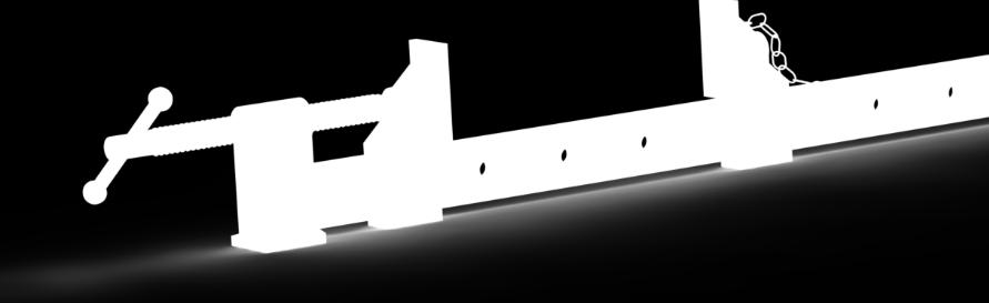
35 The Chain added Sash Clamp SW 2015 Design & Communication Graphics Page 35
Spatula. Spatula SW 2015 Design & Communication Graphics Page 1
 Spatula Introduction: The model shown in the picture is made of three parts, - the base, the washer and the handle. The base requires the use of Spline and Style Spline command, Slot command and Mirror
SolidWorks Design & Technology
 SolidWorks Design & Technology Training Course at PHSG Ex 5. Lego man Working with part files 8mm At first glance the Lego man looks complicated but I hope you will see that if you approach a project one
Digital Camera Exercise
 Commands Used New Part This lesson includes Sketching, Extruded Boss/Base, Extruded Cut, Fillet, Chamfer and Text. Click File, New on the standard toolbar. Select Part from the New SolidWorks Document
AEROPLANE. Create a New Folder in your chosen location called Aeroplane. The four parts that make up the project will be saved here.
 AEROPLANE Prerequisite Knowledge Previous knowledge of the following commands is required to complete this lesson. Sketching (Line, Rectangle, Arc, Add Relations, Dimensioning), Extrude, Assemblies and
Clock Exercise (Inserting Planes)
") Clock Exercise (Inserting Planes) Prerequisite Knowledge To complete this exercise you will need to be familiar with Sketching, Applying relations, Extrude Boss/ Base, Extrude cut, Applying Textures, Renaming
Clock Exercise (Inserting Planes) Prerequisite Knowledge To complete this exercise you will need to be familiar with Sketching, Applying relations, Extrude Boss/ Base, Extrude cut, Applying Textures, Renaming
Introduction to Circular Pattern Flower Pot
 Prerequisite Knowledge Previous knowledge of the sketching commands Line, Circle, Add Relations, Smart Dimension is required to complete this lesson. Previous examples of Revolved Boss/Base, Cut Extrude,
Engineering Technology
 Engineering Technology Introduction to Parametric Modelling Engineering Technology 1 See Saw Exercise Part 1 Base Commands used New Part This lesson includes Sketching, Extruded Boss/Base, Hole Wizard,
SolidWorks Part I - Basic Tools SDC. Includes. Parts, Assemblies and Drawings. Paul Tran CSWE, CSWI
 SolidWorks 2015 Part I - Basic Tools Includes CSWA Preparation Material Parts, Assemblies and Drawings Paul Tran CSWE, CSWI SDC PUBLICATIONS Better Textbooks. Lower Prices. www.sdcpublications.com Powered
EXERCISE ONE: BEACH BUGGY.
 EXERCISE ONE: BEACH BUGGY. Prerequisite knowledge Students should have completed Exercises from the file: Introduction to Assemblies Concept Mates Focus of lesson Commands Used This lesson will focus on
Veerapandian.K Mechanical Engg Vedharanyam A manual to mechanical designers How Solid works Works?
 Compiled by Veerapandian.K Mechanical Engg Vedharanyam-614 810 A manual to mechanical designers How Solid works Works? Solid works Overview Solid works main idea is user to create drawing directly in 3D
Purlin Roof. Create a New Folder in your chosen location called Purlin Roof. The nine parts that make up the project will be saved here.
 Purlin Roof Prerequisite Knowledge Previous knowledge of the following commands is required to complete this lesson. Sketching (Line, Rectangle, Add Relations, Dimensioning), Inserting Planes, Extrude,
Toothbrush Holder. A drawing of the sheet metal part will also be created.
 Prerequisite Knowledge Previous knowledge of the following commands is required to complete this lesson; Sketch (Line, Centerline, Circle, Add Relations, Smart Dimension,), Extrude Boss/Base, and Edit
Introduction to Sheet Metal Features SolidWorks 2009
 SolidWorks 2009 Table of Contents Introduction to Sheet Metal Features Base Flange Method Magazine File.. 3 Envelopment & Development of Surfaces.. 14 Development of Transition Pieces.. 23 Conversion to
Model House Exercise-( Extrude)
") -( Extrude) Prerequisite knowledge Focus of the lesson Commands Used This lesson requires an understanding of using the sketch commands including Inserting a new sketch Adding sketch geometry Understanding
-( Extrude) Prerequisite knowledge Focus of the lesson Commands Used This lesson requires an understanding of using the sketch commands including Inserting a new sketch Adding sketch geometry Understanding
Solidworks: Lesson 4 Assembly Basics and Toolbox. UCF Engineering
 Solidworks: Lesson 4 Assembly Basics and Toolbox UCF Engineering Solidworks We have now completed the basic features of part modeling and it is now time to begin constructing more complex models in the
Hydro Hull. Chapter 21. Boat. A. Save as "HYDRO". Step 1. Open your HULL MID PLANE file (Chapter 2).
.") Chapter 21 Boat Hydro Hull A. Save as "HYDRO". Step 1. Open your HULL MID PLANE file (Chapter 2). Step 2. Click File Menu > Save As. Step 3. Key-in HYDRO for the filename and press ENTER. B. Delete Loft1,
Chapter 21 Boat Hydro Hull A. Save as "HYDRO". Step 1. Open your HULL MID PLANE file (Chapter 2). Step 2. Click File Menu > Save As. Step 3. Key-in HYDRO for the filename and press ENTER. B. Delete Loft1,
From the above fig. After sketching the path and profile select the sweep command First select the profile from property manager tree And then select
 Chapter 5 In sweep command there is a) Two sketch profiles b) Two path c) One sketch profile and one path The sweep profile is used to create threads springs circular things and difficult geometry. For
Engineering & Computer Graphics Workbook Using SolidWorks 2014
 Engineering & Computer Graphics Workbook Using SolidWorks 2014 Ronald E. Barr Thomas J. Krueger Davor Juricic SDC PUBLICATIONS Better Textbooks. Lower Prices. www.sdcpublications.com Powered by TCPDF (www.tcpdf.org)
Engineering & Computer Graphics Workbook Using SOLIDWORKS
 Engineering & Computer Graphics Workbook Using SOLIDWORKS 2017 Ronald E. Barr Thomas J. Krueger Davor Juricic SDC PUBLICATIONS Better Textbooks. Lower Prices. www.sdcpublications.com Powered by TCPDF (www.tcpdf.org)
Feature-Based Modeling and Optional Advanced Modeling. ENGR 1182 SolidWorks 05
 Feature-Based Modeling and Optional Advanced Modeling ENGR 1182 SolidWorks 05 Today s Objectives Feature-Based Modeling (comprised of 2 sections as shown below) 1. Breaking it down into features Creating
Introduction to Revolve - A Glass
 Introduction to Revolve - A Glass Design & Communication Graphics 1 Object Analysis sheet Design & Communication Graphics 2 Prerequisite Knowledge Previous knowledge of the following commands are required
Beginner s Guide to SolidWorks Alejandro Reyes, MSME Certified SolidWorks Professional and Instructor SDC PUBLICATIONS
 Beginner s Guide to SolidWorks 2008 Alejandro Reyes, MSME Certified SolidWorks Professional and Instructor SDC PUBLICATIONS Schroff Development Corporation www.schroff.com www.schroff-europe.com Part Modeling
Wireless Mouse Surfaces
 Wireless Mouse Surfaces Design & Communication Graphics Table of Contents Table of Contents... 1 Introduction 2 Mouse Body. 3 Edge Cut.12 Centre Cut....14 Wheel Opening.. 15 Wheel Location.. 16 Laser..
Lab 3 Introduction to SolidWorks I Silas Bernardoni 10/9/2008
 1 Introduction This lab is designed to provide you with basic skills when using the 3D modeling program SolidWorks. You will learn how to build parts, assemblies and drawings. You will be given a physical
g. Click once on the left vertical line of the rectangle.
 This drawing will require you to a model of a truck as a Solidworks Part. Please be sure to read the directions carefully before constructing the truck in Solidworks. Before submitting you will be required
SDC. SolidWorks Tutorial 2001Plus. A Competency Project Based Approach Utilizing 3D Solid Modeling. David C. Planchard & Marie P.
 2001Plus A Competency Project Based Approach Utilizing 3D Solid Modeling David C. Planchard & Marie P. Planchard SDC PUBLICATIONS www.schroff.com www.schroff-europe.com Project 2 Below are the desired
Lesson 6 2D Sketch Panel Tools
 Lesson 6 2D Sketch Panel Tools Inventor s Sketch Tool Bar contains tools for creating the basic geometry to create features and parts. On the surface, the Geometry tools look fairly standard: line, circle,
Solidworks tutorial. 3d sketch project. A u t h o r : M. G h a s e m i. C o n t a c t u s : i n f s o l i d w o r k s a d v i s o r.
 Solidworks tutorial 3d sketch project A u t h o r : M. G h a s e m i C o n t a c t u s : i n f o @ s o l i d w o r k s a d v i s o r. c o m we will create this frame during the tutorial : In this tutorial
Introducing SolidWorks
 Introducing SolidWorks SAAST Robotics 2008 SolidWorks Software Visually-based 3-D Mechanical design software Engineers and Designers use it to: Quickly sketch out ideas Experiment with features, dimensions
SolidWorks Navigation
 SolidWorks Basics SolidWorks Navigation Command Bar Feature Tree Model Window Simple Box Select the Front plane Create a new sketch Create a Center Rectangle from the origin Smart Dimension the length
Beginner s Guide to SolidWorks Level I
 Beginner s Guide to SolidWorks 2014 - Level I Parts, Assemblies, Drawings, PhotoView 360 and Simulation Xpress Videos Now includes SolidWorks training videos Alejandro Reyes MSME, CSWP, CSWI Multimedia
Beginner s Guide to SolidWorks Level I
 Beginner s Guide to SolidWorks 2013 - Level I Parts, Assemblies, Drawings, Simulation Xpress Alejandro Reyes MSME, CSWP, CSWI SDC PUBLICATIONS Schroff Development Corporation Better Textbooks. Lower Prices.
Alternatively, the solid section can be made with open line sketch and adding thickness by Thicken Sketch.
 Sketcher All feature creation begins with two-dimensional drawing in the sketcher and then adding the third dimension in some way. The sketcher has many menus to help create various types of sketches.
DEPARTMENT OF MECHANICAL AND INDUSTRIAL ENGINEERING NORTHEASTERN UNIVERSITY
 DEPARTMENT OF MECHANICAL AND INDUSTRIAL ENGINEERING NORTHEASTERN UNIVERSITY CAPSULE PROGRAM Funded by NSF grant #0833636 Tutorial 02 3D Part Modeling SolidWorks 2010 Copyright 2010 Prof. Zeid 3D Part Modeling
Chair. Bottom Rail. on the Command Manager. on the Weldments toolbar.
 Chapter 2 Chair Bottom Rail A. Weldments Toolbar. Step 1. Click File Menu > New, click Part and OK. Step 2. Right click Sketch on the Command Manager toolbar and select Weldments, Fig. 1. Step 3. Click
SolidWorks 95 User s Guide
 SolidWorks 95 User s Guide Disclaimer: The following User Guide was extracted from SolidWorks 95 Help files and was not originally distributed in this format. All content 1995, SolidWorks Corporation Contents
Foreword. If you have any questions about these tutorials, drop your mail to
 Foreword The main objective of these tutorials is to give you a kick start using Solidworks. The approach to write this tutorial is based on what is the most important knowledge you should know and what
Inventor-Parts-Tutorial By: Dor Ashur
 Inventor-Parts-Tutorial By: Dor Ashur For Assignment: http://www.maelabs.ucsd.edu/mae3/assignments/cad/inventor_parts.pdf Open Autodesk Inventor: Start-> All Programs -> Autodesk -> Autodesk Inventor 2010
Assembly Receiver/Hitch/Ball/Pin to use for CAD LAB 5A and 5B:
 MECH 130 CAD LAB 5 SPRING 2017 due Friday, April 21, 2016 at 4:30 PM All of LAB 5 s hardcopies will be working drawing layouts. Do not print out from the part file. We will be using the ME130DRAW drawing
Introduction to Autodesk Inventor for F1 in Schools (Australian Version)
") Introduction to Autodesk Inventor for F1 in Schools (Australian Version) F1 in Schools race car In this course you will be introduced to Autodesk Inventor, which is the centerpiece of Autodesk s Digital
Introduction to Autodesk Inventor for F1 in Schools (Australian Version) F1 in Schools race car In this course you will be introduced to Autodesk Inventor, which is the centerpiece of Autodesk s Digital
Shaft Hanger - SolidWorks
 ME-430 INTRODUCTION TO COMPUTER AIDED DESIGN Shaft Hanger - SolidWorks BY: DR. HERLI SURJANHATA ASSIGNMENT Submit TWO isometric views of the Shaft Hanger with your report, 1. Shaded view of the trimetric
Cube in a cube Fusion 360 tutorial
 Cube in a cube Fusion 360 tutorial n Before using these instructions, it is helpful to watch this video screencast of the CAD drawing actually being done in the software. Click to link to the video tutorial.
Introduction to 3D CAD with SolidWorks. Jianan Li
 Introduction to 3D CAD with SolidWorks Jianan Li Create a New Part The first time you launch SolidWorks, it asks you to set the default units and dimension standard. Make sure you have IPS and ANSI selected,
Creo Revolve Tutorial
 Creo Revolve Tutorial Setup 1. Open Creo Parametric Note: Refer back to the Creo Extrude Tutorial for references and screen shots of the Creo layout 2. Set Working Directory a. From the Model Tree navigate
LABORATORY MANUAL COMPUTER AIDED DESIGN LAB
 LABORATORY MANUAL COMPUTER AIDED DESIGN LAB Sr. No 1 2 3 Experiment Title Setting up of drawing environment by setting drawing limits, drawing units, naming the drawing, naming layers, setting line types
Bottom Rail. Chapter 2. Chair. A. Weldments Toolbar. Step 1. Click File Menu > New, click Part and OK. B. 3D Sketch.
 Chapter 2 Chair Bottom Rail A. Weldments Toolbar. Step 1. Click File Menu > New, click Part and OK. Step 2. Right click Sketch on the Command Manager toolbar and select Weldments, Fig. 1. Step 3. Click
1. Open the Feature Modeling demo part file on the EEIC website. Ask student about which constraints needed to Fully Define.
 BLUE boxed notes are intended as aids to the lecturer RED boxed notes are comments that the lecturer could make Control + Click HERE to view enlarged IMAGE and Construction Strategy he following set of
Solidworks Tutorial Pencil
 The following instructions will be used to help you create a Pencil using Solidworks. These instructions are ordered to make the process as simple as possible. Deviating from the order, or not following
ME Week 2 Project 2 Flange Manifold Part
 1 Project 2 - Flange Manifold Part 1.1 Instructions This project focuses on additional sketching methods and sketching commands. Revolve and Work features are also introduced. The part being modeled is
SolidWize. Online SolidWorks Training. Simple Sweep: Head Scratcher
 SolidWize Online SolidWorks Training Simple Sweep: Head Scratcher Step 1: Creating the Handle: Sketch Using Inches as the unit create a sketch on the Front plane. Start with the sketch shown below: Create
Lesson 10: Loft Features
 10 Goals of This Lesson Your students will be able to create the following part: profiles chisel This lesson plan corresponds to the Loft Features chapter of SolidWorks Getting Started. SolidWorks Student
Computer Aided Design Module 2. Lesson Toblerone Bar
 Computer Aided Design Module 2 Lesson Toblerone Bar Lesson? Toblerone Bar New Commands used: Polygon, Add Relations, Smart Dimension, Extrude Boss/Base (Mid Plane), Fillet, Line, Extrude-Cut, Linear Pattern
Introduction to CATIA V5
 Introduction to CATIA V5 Release 17 (A Hands-On Tutorial Approach) Kirstie Plantenberg University of Detroit Mercy SDC PUBLICATIONS Schroff Development Corporation www.schroff.com Better Textbooks. Lower
Lesson 4 Holes and Rounds
 Lesson 4 Holes and Rounds 111 Figure 4.1 Breaker OBJECTIVES Sketch arcs in sections Create a straight hole through a part Complete a Sketched hole Understand the Hole Tool Use Info to extract information
for Solidworks TRAINING GUIDE LESSON-9-CAD
 for Solidworks TRAINING GUIDE LESSON-9-CAD Mastercam for SolidWorks Training Guide Objectives You will create the geometry for SolidWorks-Lesson-9 using SolidWorks 3D CAD software. You will be working
1.6.7 Add Arc Length Dimension Modify Dimension Value Check the Sketch Curve Connectivity
 Contents 2D Sketch... 1 1.1 2D Sketch Introduction... 1 1.1.1 2D Sketch... 1 1.1.2 Basic Setting of 2D Sketch... 2 1.1.3 Exit 2D Sketch... 4 1.2 Draw Common Geometry... 5 2.2.1 Points... 5 2.2.2 Lines
Part Design. Sketcher - Basic 1 13,0600,1488,1586(SP6)
") Part Design Sketcher - Basic 1 13,0600,1488,1586(SP6) In this exercise, we will learn the foundation of the Sketcher and its basic functions. The Sketcher is a tool used to create two-dimensional (2D)
Part Design Sketcher - Basic 1 13,0600,1488,1586(SP6) In this exercise, we will learn the foundation of the Sketcher and its basic functions. The Sketcher is a tool used to create two-dimensional (2D)
10/14/2010. Chevy Malibu. Vehicle Design with Solidworks. Start SolidWorks Create a New SolidWorks Document. Miles, Rowardo B
 Chevy Malibu Vehicle Design with Solidworks Start SolidWorks Create a New SolidWorks Document Miles, Rowardo B 1 Click: Part and then OK Now you are ready to make a Part. 2 Right Toolbar: Document Properties:
Explanation of buttons used for sketching in Unigraphics
 Explanation of buttons used for sketching in Unigraphics Sketcher Tool Bar Finish Sketch is for exiting the Sketcher Task Environment. Sketch Name is the name of the current active sketch. You can also
Part Design Fundamentals
 Part Design Fundamentals 1 Course Presentation Objectives of the course In this course you will learn basic methods to create and modify solids features and parts Targeted audience New CATIA V5 Users 1
Dual clip mould In the following exercise you will create a full 2 cavity mould of your dual clip mould component.
 Dual clip mould 2018 In the following exercise you will create a full 2 cavity mould of your dual clip mould component. The mould is required to be a 2 cavity mould and must contain all the necessary detail
SolidWorks 2013 Part I - Basic Tools
 SolidWorks 2013 Part I - Basic Tools Parts, Assemblies and Drawings Paul Tran CSWE, CSWI Supplemental Files SDC PUBLICATIONS Schroff Development Corporation Better Textbooks. Lower Prices. www.sdcpublications.com
Introduction to SolidWorks Introduction to SolidWorks
 Introduction to SolidWorks Introduction to SolidWorks SolidWorks is a powerful 3D modeling program. The models it produces can be used in a number of ways to simulate the behaviour of a real part or assembly
Creo Parametric 2.0: Introduction to Solid Modeling. Creo Parametric 2.0: Introduction to Solid Modeling
 Creo Parametric 2.0: Introduction to Solid Modeling 1 2 Part 1 Class Files... xiii Chapter 1 Introduction to Creo Parametric... 1-1 1.1 Solid Modeling... 1-4 1.2 Creo Parametric Fundamentals... 1-6 Feature-Based...
LAB 1A: Intro to SolidWorks: 2D -> 3D Brackets
 LAB 1A: Intro to SolidWorks: 2D -> 3D Brackets Set units Create Sketch Add relations Linear patterns Mirror Fillet Extrude Extrude cut First, set units. click Option on top of main menu Open Document Properties
SolidWorks 2014 Part I - Basic Tools
 SolidWorks 2014 Part I - Basic Tools Parts, Assemblies and Drawings Paul Tran CSWE, CSWI SDC PUBLICATIONS Better Textbooks. Lower Prices. www.sdcpublications.com Powered by TCPDF (www.tcpdf.org) Visit
Starting a 3D Modeling Part File
 1 How to Create a 3D Model and Corresponding 2D Drawing with Dimensions, GDT (Geometric Dimensioning and Tolerance) Symbols and Title Block in SolidWorks 2013-2014 By Edward Locke This tutorial will introduce
Introduction to Sweep - Allen Key part (A)
") Introduction to Sweep - Allen Key part (A) Prerequisite Knowledge Previous knowledge of the following commands is required to complete this lesson, sketching (line construction, dimensioning, polygon).
Introduction to Sweep - Allen Key part (A) Prerequisite Knowledge Previous knowledge of the following commands is required to complete this lesson, sketching (line construction, dimensioning, polygon).
SolidWorks Tutorial 1. Axis
 SolidWorks Tutorial 1 Axis Axis This first exercise provides an introduction to SolidWorks software. First, we will design and draw a simple part: an axis with different diameters. You will learn how to
Advance Dimensioning and Base Feature Options
 Chapter 4 Advance Dimensioning and Base Feature Options Learning Objectives After completing this chapter you will be able to: Dimension the sketch using the autodimension sketch tool. Dimension the sketch
SOLIDWORKS 2016 Advanced Techniques
 SOLIDWORKS 2016 Advanced Techniques Mastering Parts, Surfaces, Sheet Metal, SimulationXpress, Top Down Assemblies, Core & Cavity Molds Paul Tran CSWE, CSWI SDC PUBLICATIONS Better Textbooks. Lower Prices.
How to Build a Game Console. David Hunt, PE
 How to Build a Game Console David Hunt, PE davidhunt@outdrs.net Covering: Drafts Fillets Shells Patterns o Linear o Circular Using made-for-the-purpose sketches to define reference geometry Using reference
Modeling Basic Mechanical Components #1 Tie-Wrap Clip
 Modeling Basic Mechanical Components #1 Tie-Wrap Clip This tutorial is about modeling simple and basic mechanical components with 3D Mechanical CAD programs, specifically one called Alibre Xpress, a freely
Modeling an Airframe Tutorial
 EAA SOLIDWORKS University p 1/11 Difficulty: Intermediate Time: 1 hour As an Intermediate Tutorial, it is assumed that you have completed the Quick Start Tutorial and know how to sketch in 2D and 3D. If
SolidWorks Training. Introductory course for staff and students from the School of Physics and Astronomy
 SolidWorks Training Introductory course for staff and students from the School of Physics and Astronomy i) Introductory presentation SolidWorks Training ii) The SolidWorks GUI The SolidWorks Graphical
J. La Favre Fusion 360 Lesson 2 April 19, 2017
 In this lesson, you will create a round plate with 12 counter-bored holes to fit 6-32 socket head screws. A counter-bored hole has two diameters, one to fit the threaded part of the screw and the other
Using Siemens NX 11 Software. The connecting rod
 Using Siemens NX 11 Software The connecting rod Based on a Catia tutorial written by Loïc Stefanski. At the end of this manual, you should obtain the following part: 1 Introduction. Start NX 11 and open
Module 2: Radial-Line Sheet-Metal 3D Modeling and 2D Pattern Development: Right Cone (Regular, Frustum, and Truncated)
") Inventor (5) Module 2: 2-1 Module 2: Radial-Line Sheet-Metal 3D Modeling and 2D Pattern Development: Right Cone (Regular, Frustum, and Truncated) In this tutorial, we will learn how to build a 3D model
Inventor (5) Module 2: 2-1 Module 2: Radial-Line Sheet-Metal 3D Modeling and 2D Pattern Development: Right Cone (Regular, Frustum, and Truncated) In this tutorial, we will learn how to build a 3D model
Understanding Projection Systems
 Understanding Projection Systems A Point: A point has no dimensions, a theoretical location that has neither length, width nor height. A point shows an exact location in space. It is important to understand
Activity 5.5a CAD Model Features Part 1
 Activity 5.5a CAD Model Features Part 1 Introduction In order to use CAD effectively as a design tool, the designer must have the skills necessary to create, edit, and manipulate a 3D model of a part in
SolidWorks 2005 Tutorial. and MultiMedia CD. A Step-by-step Project Based Approach Utilizing 3D Solid Modeling
 INSIDE: MultiMedia CD An audio/visual presentation of the tutorial projects SolidWorks 2005 Tutorial and MultiMedia CD A Step-by-step Project Based Approach Utilizing 3D Solid Modeling David C. Planchard
Quick Start for Autodesk Inventor
 Quick Start for Autodesk Inventor Autodesk Inventor Professional is a 3D mechanical design tool with powerful solid modeling capabilities and an intuitive interface. In this lesson, you use a typical workflow
Table of Contents. Lesson 1 Getting Started
 NX Lesson 1 Getting Started Pre-reqs/Technical Skills Basic computer use Expectations Read lesson material Implement steps in software while reading through lesson material Complete quiz on Blackboard
SOLIDWORKS 2015 and Engineering Graphics
 SOLIDWORKS 2015 and Engineering Graphics An Integrated Approach Randy H. Shih SDC PUBLICATIONS Better Textbooks. Lower Prices. www.sdcpublications.com Powered by TCPDF (www.tcpdf.org) Visit the following
Chapter 2. Modifying, Extruding and Revolving the Sketches. Learning Objectives. Commands Covered AMMODDIM AMEXTRUDE AMREVOLVE
 Chapter 2 Modifying, Extruding and Revolving the Sketches Learning Objectives After completing this chapter, you will be able to: Modify the desired sketch using the AMMODDIM command. Extrude the desired
Diane Burton, STEM Outreach.
 123D Design Tutorial: LED decoration Before using these instructions, it is very helpful to watch this video screencast of the CAD drawing actually being done in the software. Click this link for the video
On completion of this exercise you will have:
 Prerequisite Knowledge To complete this exercise you will need; to be familiar with the SolidWorks interface and the key commands. basic file management skills the ability to rotate views and select faces
Evaluation Chapter by CADArtifex
 The premium provider of learning products and solutions www.cadartifex.com EVALUATION CHAPTER 2 Drawing Sketches with SOLIDWORKS In this chapter: Invoking the Part Modeling Environment Invoking the Sketching
SolidWorks 103: Barge Design Challenge
 SolidWorks 103: Barge Design Challenge Note: This tutorial was created using SolidWorks 2009. If you are using another version of SolidWorks, you may notice some variation in display states and configuration.
DUE DATE: Friday 4/6/2018 at 3:30 PM
 MECH 130 SPRING 2018 CAD LAB 4 FINAL REVISION HARDCOPIES NEEDED DUE DATE: Friday 4/6/2018 at 3:30 PM After the revised hitch, the ball and the pin parts were created from the Handout call LAB4 PART Creation,
Name: Date Completed: Basic Inventor Skills I
 Name: Date Completed: Basic Inventor Skills I 1. Sketch, dimension and extrude a basic shape i. Select New tab from toolbar. ii. Select Standard.ipt from dialogue box by double clicking on the icon. iii.
Creo Extrude Tutorial 3: Hole, Fillets and Rounds
 Creo Extrude Tutorial 3: Hole, Fillets and Rounds By: Matthew Jourden Brighton High School 1. Open Creo Parametric 2. File > Open > extrudetutorial (From Creo Extrude Tutorial 1) NOTE: Minimum of 2 other
Introduction To Modeling
 Introduction To Modeling Introduction ProEngineer Wildfire2 is a computer aided design (CAD) program that is used to create models on a computer in three-dimensions. Since three dimensions are used the
Using Siemens NX 11 Software. Sheet Metal Design - Casing
 Using Siemens NX 11 Software Sheet Metal Design - Casing Based on a YouTube NX tutorial 1. 1 https://www.youtube.com/watch?v=-siyi1vz87k A&M CAD in mechanical engineering 1 1 Introduction. Start NX 11
1. Create a 2D sketch 2. Create geometry in a sketch 3. Use constraints to position geometry 4. Use dimensions to set the size of geometry
 2.1: Sketching Many features that you create in Fusion 360 start with a 2D sketch. In order to create intelligent and predictable designs, a good understanding of how to create sketches and how to apply
Chapter 2. Drawing Sketches for Solid Models. Learning Objectives
 Chapter 2 Drawing Sketches for Solid Models Learning Objectives After completing this chapter, you will be able to: Start a new template file to draw sketches. Set up the sketching environment. Use various
CREO.1 MODELING A BELT WHEEL
 CREO.1 MODELING A BELT WHEEL Figure 1: A belt wheel modeled in this exercise. Learning Targets In this exercise you will learn: Using symmetry when sketching Using pattern to copy features Using RMB when
and Engineering Graphics
 SOLIDWORKS 2018 and Engineering Graphics An Integrated Approach Randy H. Shih SDC PUBLICATIONS Better Textbooks. Lower Prices. www.sdcpublications.com Powered by TCPDF (www.tcpdf.org) Visit the following