Introducing SolidWorks
|
|
|
- Arabella Marsh
- 6 years ago
- Views:
Transcription

1 Introducing SolidWorks SAAST Robotics 2008
2 SolidWorks Software Visually-based 3-D Mechanical design software Engineers and Designers use it to: Quickly sketch out ideas Experiment with features, dimensions Produce solid models and detailed mechanical drawings
3 SolidWorks Fundamentals
4 Design Intent Design intent determines how you want the model to react as a result of changes you make Planning: deciding how to create model determines how changes affect it Factors that define it: Current needs understand the purpose of the model to design it efficiently Future considerations anticipate potential requirements to minimize redesign efforts when changing model
5 Design Method Develop the model with the following steps Sketches create, decide how to dimension, where to apply relations, etc. Features select appropriate features, determine best features to apply and in what order Assemblies select what components to mate, what types of mates, etc. (we will discuss this next lecture)

6 Real-World Examples UPENN Formula SAE Team Wheel Center

7 Real-World Examples UPENN Formula SAE Team Completed Car


8 Real-World Examples Sandbox Innovations Research & Development Kit
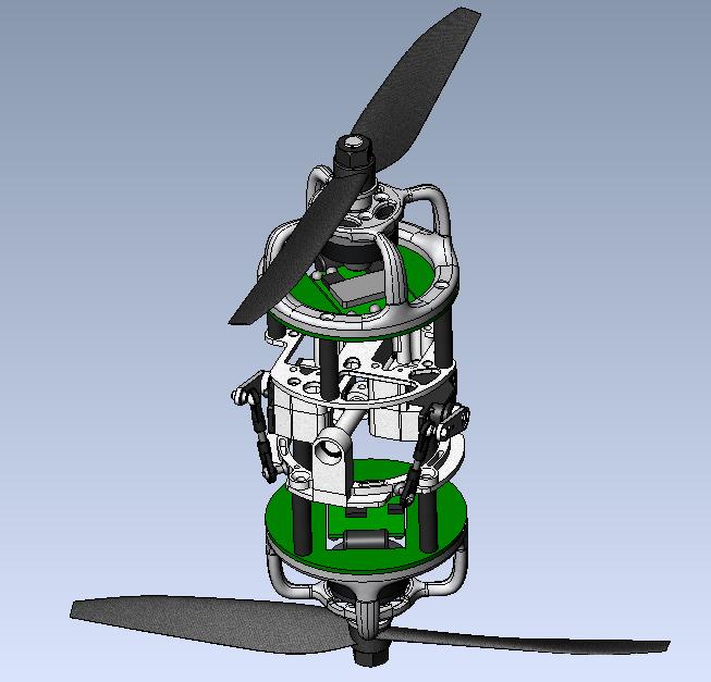
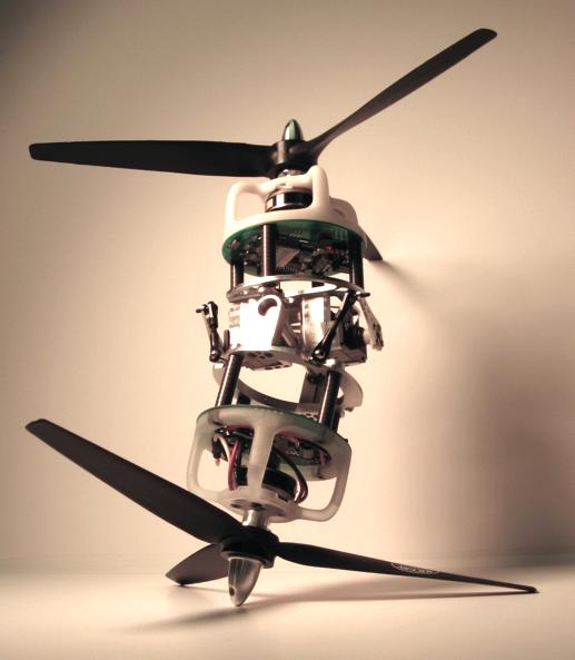
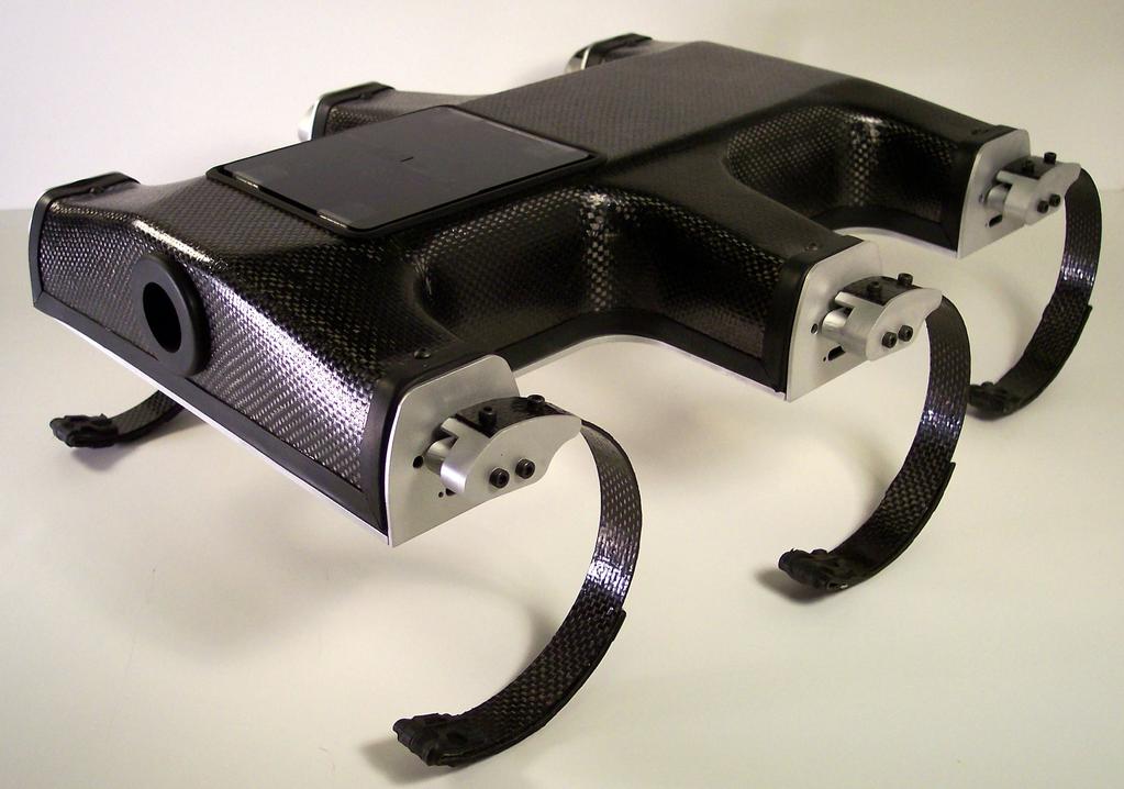
9 Real-World Examples MACAV UPENN modlab
10 User Interface Windows functions Dragging, resizing windows, open, save, cut, paste, print, etc. Open a document: drag part from Windows Explorer in blank SW document Create a drawing: drag a part into blank drawing document to create one or more views of part Create an assy: drag components in blank assy document to mate together and create assy Keyboard shortcuts: Ctrl+O open file, Ctrl+S save, Ctrl+Z undo task

11 User Interface SW Document Windows FeatureManager design tree lists structure of the part, assy, or drawing Select element from tree to edit sketch, feature, supress, unsupress feature or component, etc. PropertyManager displays relevant info along with user-interface capabilities Graphics area

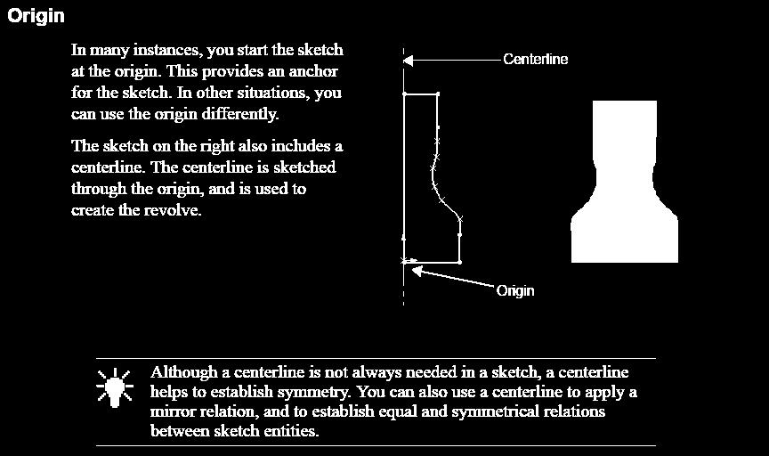
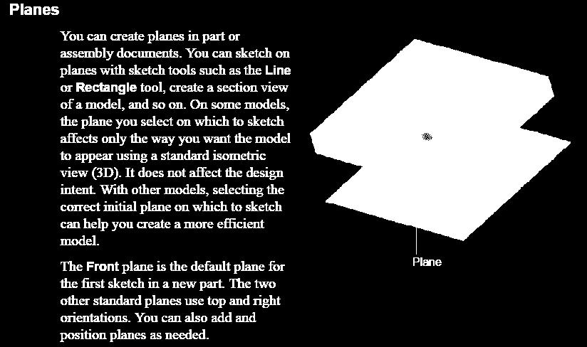
12 Terminology Origin: appears as arrows, represents (0,0,0) of model. In active sketches, appears in red and is (0,0,0) of sketch. Can add relations to model origin, not to sketch origin Plane: flat construction geometry Use for adding a 2D sketch, section view of model, etc. Axis: straight line used to create model geometry, features, patterns Face: boundaries that define the shape of model or surface Selectable area of model or surface Edge: location where two faces or surfaces meet along a distance Select edges for sketching, dimensioning, etc. Vertex: point at which two or more lines or edges intersect Select vertices for sketching, dimensioning, etc.
13 Function Selection and Feedback Able to perform tasks in different ways Get feedback as perform task pointers, inference lines, previews, etc. Menus All SW commands accessible via menus Standard Windows conventions sub-menus, check marks indicating active Toolbars Access SW functions with toolbars organized by function, i.e. Sketch toolbar, Assy toolbar. Each has individual icons that represent specific tools Display/hide, dock/undock/float, add/delete, customize Mouse Buttons Left selects menu items, entities in graphics area, objects in FeatureManager design tree Right displays context-sensitive shortcut menus Middle rotates, pans, and zooms part or assy, pans in a drawing
14 Sketches Models begin with a sketch Sketch features One or more features part Combine and mate parts assembly Parts or assembly drawings Sketch 2D profile or cross-section Create using a plane or planar face All include the following elements: Origin Plane Dimensions Relations
15 Sketches
16 Sketches
17 Sketches Dimensions Specify dimensions and relations between entities Dimensions define length, radius, angle, etc. When change dimensions, the size and shape of part changes Depending on how you dimension part, design intent can be preserved Keep one dimension constant while you change others Driving and driven dimensions


18 Sketches Driving Dimensions Change the size of the model when you change their value To maintain uniform shape from spline, need to dimension it

19 Sketches Driven Dimensions Created by SW, used for information only Can be deleted but not modified Change when you modify driving dimensions Deciding which dimensions are the driving and which are driven affects your design
20 Sketches Sketch definitions Fully defined (black): all lines and curves in sketch and their positions are described by dimensions, or relations, or both Don t need to be fully defined to create feature, should be fully defined to complete a finished part Under defined (blue): entities not fully described Under defined entities are not fixed within sketch so you can drag them Over defined (red): sketches that include redundant dimensions or relations Can be deleted but cannot edit them
 between sketch entities Apply two ways: Inference: assumed by SW as draw sketch Add Relations tool: choose type of relation to")
21 Sketches Relations establish geometric relations (equal, tangent, concentric, etc.) between sketch entities Apply two ways: Inference: assumed by SW as draw sketch Add Relations tool: choose type of relation to apply Equality between two horizontal lines same length

22 Sketches Sketch complexity simplify sketches by: Applying relations as you sketch Taking advantage of repetition and symmetry Example mirror left and right sides using Centerline creates auto relations and dimensions Inference the position of arcs from Origin Dimension and add concentric relation between inner arcs and outer arc of base once

23 Function Selection and Feedback


24 Function Selection and Feedback
25 Function Selection and Feedback Selection Filters Help you select particular type of entity, excluding selection of other entity types Example: to select an edge, select Filter Edges to exclude other entities Select Other Use to scroll through multiple edges or faces in part, including ones that are hidden

26 Features Completed sketch Feature Sketch-based features Bosses, cuts, holes, extrudes, lofts, sweeps Features such as Lofts, sweeps Require a profile along a path Applied feature: fillets, chamfers, shell, thicken, etc.


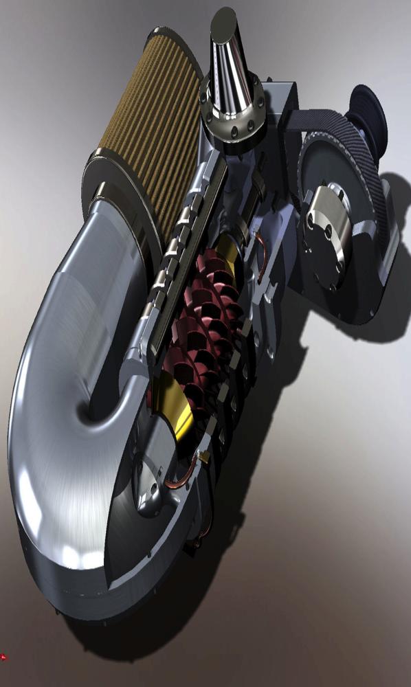
27 Features Sweep 3D Fillet

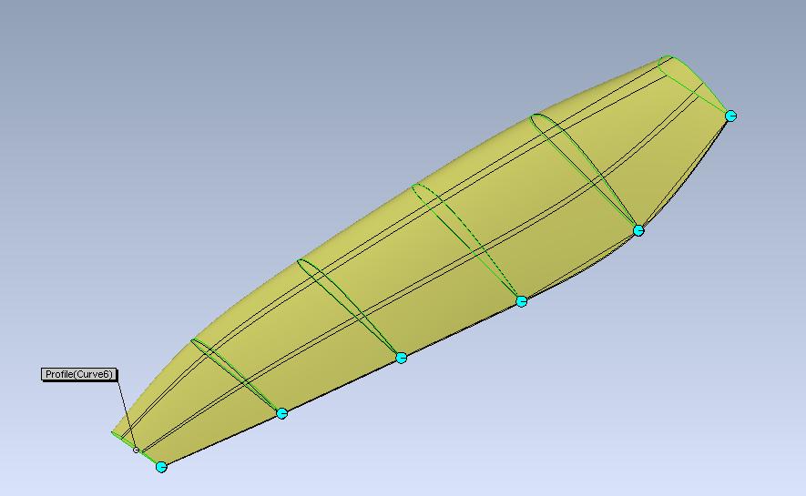

28 Features Lofts

29 Assemblies Multiple parts assemblies Assemble parts using Mates Coincident, colinear, parallel, etc. Tools Move Component, Rotate Component Collision Detection, Interference Detection
, auxiliary Import dimensions from model Add annotations, bill of")
30 Drawings Create drawings from part or assembly Multiple views Standard 3 views, isometric (3D), auxiliary Import dimensions from model Add annotations, bill of materials (BOM)

31 Model Editing Edit sketch edit sketch entities (lines), change dimensions, view/ delete/add relations Edit feature change values associated with feature Edit definition to display PropertyManager Hide and show hide/show surface bodies, sketches, views, lines, components Suppress and unsupress view model with or without particular feature, or part in assy s with/without components Rollback roll up the FeatureManager design tree back to prior state
32 Resources SW Online Tutorial SW Online Help SolidWorks website Google
33 Parts


34 Parts Building blocks for SolidWorks models Used to create assemblies and drawings Overview Learn tools for feature and part creation Design approach


35 Countertop Example Single part - includes sink and counter First create counter, then make the sink


36 Countertop Example Create Base Feature with Extrude Create a sketch of a rectangle at origin Dimension and add relations to fully define sketch Extrude sketch


37 Countertop Example Add an Extrude to the Base Create L-shaped sketch on face of extrusion Extrude sketch


38 Countertop Example Remove material with Cut-Extrude Similar to extrude except cuts material instead of adding it Create sketch of ellipse on face of base Cut through-all of base
 Create Plane1")
 Create point on sketch on Plane1 Use Loft tool to connect the")
39 Countertop Example Use Loft to make a solid Loft: solid feature created that connects two or more sketch profiles (remember the propeller) Create Plane1 offset from Top plane (Insert Reference Geom) Sketch ellipse on bottom of base (Convert Entities) Create point on sketch on Plane1 Use Loft tool to connect the two sketches


40 Countertop Example Shell the Part Loft created a solid feature Use shell tool to cut out material Shell tool: selected faces are removed and thin faces remain on the rest of the part

41 Countertop Example Round sharp edges with Fillets Fillet: internal rounding of an edge on a surface or solid Applied feature don t need to create sketch to apply them Select edges of existing feature Set radius Create fillet


42 Countertop Example: Faucet Sketch 1 base profile Extrude sketch 1 Sketch 2 two circles on bottom of base Extrude sketch 2

43 Countertop Example: Faucet Sweep tool to make spigot Profile circular sketch (crosssection) Path sketched arc, tangent to a vertical line Starting point of path must lie on the same plane as profile Add additional extrudes and fillets

44 Countertop Example: Faucet Handle Two revolved features Fillet feature

45 Countertop Example: Faucet Handle Revolve the Sketch Create sketch with Line and Spline tools Add centerline for construction geometry Use Revolved Boss/Base tool to rotate sketch 360 to create solid feature


46 Countertop Example: Faucet Handle Create Second Revolve Create sketch with Line, Tangent Arc, and Spline tools Add centerline for construction geometry Use Revolved Boss/Base tool to rotate sketch 360 to create solid feature Add cosmetic fillets
47 Other Useful Tools Convert entities Centerlines for centering parts instead of dimensions Edit sketch plane Trim
48 University of Pennsylvania School of Engineering and Applied Science
SolidWorks 95 User s Guide
 SolidWorks 95 User s Guide Disclaimer: The following User Guide was extracted from SolidWorks 95 Help files and was not originally distributed in this format. All content 1995, SolidWorks Corporation Contents
SolidWorks Part I - Basic Tools SDC. Includes. Parts, Assemblies and Drawings. Paul Tran CSWE, CSWI
 SolidWorks 2015 Part I - Basic Tools Includes CSWA Preparation Material Parts, Assemblies and Drawings Paul Tran CSWE, CSWI SDC PUBLICATIONS Better Textbooks. Lower Prices. www.sdcpublications.com Powered
INTRODUCING SOLIDWORKS
 INTRODUCING SOLIDWORKS Contents Legal Notices...6 Introduction...9 The SOLIDWORKS Software...9 Intended Audience...9 System Requirements...9 Document Structure...9 Conventions Used in this Document...10
Beginner s Guide to SolidWorks Level I
 Beginner s Guide to SolidWorks 2013 - Level I Parts, Assemblies, Drawings, Simulation Xpress Alejandro Reyes MSME, CSWP, CSWI SDC PUBLICATIONS Schroff Development Corporation Better Textbooks. Lower Prices.
Beginner s Guide to SolidWorks Alejandro Reyes, MSME Certified SolidWorks Professional and Instructor SDC PUBLICATIONS
 Beginner s Guide to SolidWorks 2008 Alejandro Reyes, MSME Certified SolidWorks Professional and Instructor SDC PUBLICATIONS Schroff Development Corporation www.schroff.com www.schroff-europe.com Part Modeling
Beginner s Guide to SolidWorks Level I
 Beginner s Guide to SolidWorks 2014 - Level I Parts, Assemblies, Drawings, PhotoView 360 and Simulation Xpress Videos Now includes SolidWorks training videos Alejandro Reyes MSME, CSWP, CSWI Multimedia
Essentials of SOLIDWORKS 2015 (4+ Days) * Ve-I Bonus! * File Management + SimulationXpress
 * Ve-I Bonus! * File Management + SimulationXpress") Essentials of SOLIDWORKS 2015 (4+ Days) * Ve-I Bonus! * File Management + SimulationXpress Overview What is SOLIDWORKS? Interface Tour View Manipulation Provides some background info on the SOLIDWORKS
Essentials of SOLIDWORKS 2015 (4+ Days) * Ve-I Bonus! * File Management + SimulationXpress Overview What is SOLIDWORKS? Interface Tour View Manipulation Provides some background info on the SOLIDWORKS
SolidWorks 2005 Tutorial. and MultiMedia CD. A Step-by-step Project Based Approach Utilizing 3D Solid Modeling
 INSIDE: MultiMedia CD An audio/visual presentation of the tutorial projects SolidWorks 2005 Tutorial and MultiMedia CD A Step-by-step Project Based Approach Utilizing 3D Solid Modeling David C. Planchard
Spatula. Spatula SW 2015 Design & Communication Graphics Page 1
 Spatula Introduction: The model shown in the picture is made of three parts, - the base, the washer and the handle. The base requires the use of Spline and Style Spline command, Slot command and Mirror
Engineering Technology
 Engineering Technology Introduction to Parametric Modelling Engineering Technology 1 See Saw Exercise Part 1 Base Commands used New Part This lesson includes Sketching, Extruded Boss/Base, Hole Wizard,
From the above fig. After sketching the path and profile select the sweep command First select the profile from property manager tree And then select
 Chapter 5 In sweep command there is a) Two sketch profiles b) Two path c) One sketch profile and one path The sweep profile is used to create threads springs circular things and difficult geometry. For
SDC. SolidWorks Tutorial 2001Plus. A Competency Project Based Approach Utilizing 3D Solid Modeling. David C. Planchard & Marie P.
 2001Plus A Competency Project Based Approach Utilizing 3D Solid Modeling David C. Planchard & Marie P. Planchard SDC PUBLICATIONS www.schroff.com www.schroff-europe.com Project 2 Below are the desired
Toothbrush Holder. A drawing of the sheet metal part will also be created.
 Prerequisite Knowledge Previous knowledge of the following commands is required to complete this lesson; Sketch (Line, Centerline, Circle, Add Relations, Smart Dimension,), Extrude Boss/Base, and Edit
Introduction to Circular Pattern Flower Pot
 Prerequisite Knowledge Previous knowledge of the sketching commands Line, Circle, Add Relations, Smart Dimension is required to complete this lesson. Previous examples of Revolved Boss/Base, Cut Extrude,
AEROPLANE. Create a New Folder in your chosen location called Aeroplane. The four parts that make up the project will be saved here.
 AEROPLANE Prerequisite Knowledge Previous knowledge of the following commands is required to complete this lesson. Sketching (Line, Rectangle, Arc, Add Relations, Dimensioning), Extrude, Assemblies and
Hydro Hull. Chapter 21. Boat. A. Save as "HYDRO". Step 1. Open your HULL MID PLANE file (Chapter 2).
.") Chapter 21 Boat Hydro Hull A. Save as "HYDRO". Step 1. Open your HULL MID PLANE file (Chapter 2). Step 2. Click File Menu > Save As. Step 3. Key-in HYDRO for the filename and press ENTER. B. Delete Loft1,
Chapter 21 Boat Hydro Hull A. Save as "HYDRO". Step 1. Open your HULL MID PLANE file (Chapter 2). Step 2. Click File Menu > Save As. Step 3. Key-in HYDRO for the filename and press ENTER. B. Delete Loft1,
Shaft Hanger - SolidWorks
 ME-430 INTRODUCTION TO COMPUTER AIDED DESIGN Shaft Hanger - SolidWorks BY: DR. HERLI SURJANHATA ASSIGNMENT Submit TWO isometric views of the Shaft Hanger with your report, 1. Shaded view of the trimetric
Lab 3 Introduction to SolidWorks I Silas Bernardoni 10/9/2008
 1 Introduction This lab is designed to provide you with basic skills when using the 3D modeling program SolidWorks. You will learn how to build parts, assemblies and drawings. You will be given a physical
Explanation of buttons used for sketching in Unigraphics
 Explanation of buttons used for sketching in Unigraphics Sketcher Tool Bar Finish Sketch is for exiting the Sketcher Task Environment. Sketch Name is the name of the current active sketch. You can also
Lesson 6 2D Sketch Panel Tools
 Lesson 6 2D Sketch Panel Tools Inventor s Sketch Tool Bar contains tools for creating the basic geometry to create features and parts. On the surface, the Geometry tools look fairly standard: line, circle,
10/14/2010. Chevy Malibu. Vehicle Design with Solidworks. Start SolidWorks Create a New SolidWorks Document. Miles, Rowardo B
 Chevy Malibu Vehicle Design with Solidworks Start SolidWorks Create a New SolidWorks Document Miles, Rowardo B 1 Click: Part and then OK Now you are ready to make a Part. 2 Right Toolbar: Document Properties:
Table of Contents. Dedication Preface. Chapter 1: Introduction to CATIA V5-6R2015. Chapter 2: Drawing Sketches in the Sketcher Workbench-I.
 Table of Contents Dedication Preface iii xvii Chapter 1: Introduction to CATIA V5-6R2015 Introduction to CATIA V5-6R2015 1-2 CATIA V5 Workbenches 1-2 System Requirements 1-4 Getting Started with CATIA
Introduction to SolidWorks Introduction to SolidWorks
 Introduction to SolidWorks Introduction to SolidWorks SolidWorks is a powerful 3D modeling program. The models it produces can be used in a number of ways to simulate the behaviour of a real part or assembly
SolidWorks Design & Technology
 SolidWorks Design & Technology Training Course at PHSG Ex 5. Lego man Working with part files 8mm At first glance the Lego man looks complicated but I hope you will see that if you approach a project one
Feature-Based Modeling and Optional Advanced Modeling. ENGR 1182 SolidWorks 05
 Feature-Based Modeling and Optional Advanced Modeling ENGR 1182 SolidWorks 05 Today s Objectives Feature-Based Modeling (comprised of 2 sections as shown below) 1. Breaking it down into features Creating
Lesson 10: Loft Features
 10 Goals of This Lesson Your students will be able to create the following part: profiles chisel This lesson plan corresponds to the Loft Features chapter of SolidWorks Getting Started. SolidWorks Student
Below are the desired outcomes and usage competencies based on the completion of Project 4.
 Engineering Design with SolidWorks Project 4 Below are the desired outcomes and usage competencies based on the completion of Project 4. Project Desired Outcomes: An understanding of the customer s requirements
SolidWorks 2013 Part I - Basic Tools
 SolidWorks 2013 Part I - Basic Tools Parts, Assemblies and Drawings Paul Tran CSWE, CSWI Supplemental Files SDC PUBLICATIONS Schroff Development Corporation Better Textbooks. Lower Prices. www.sdcpublications.com
Modeling Basic Mechanical Components #1 Tie-Wrap Clip
 Modeling Basic Mechanical Components #1 Tie-Wrap Clip This tutorial is about modeling simple and basic mechanical components with 3D Mechanical CAD programs, specifically one called Alibre Xpress, a freely
1. Open the Feature Modeling demo part file on the EEIC website. Ask student about which constraints needed to Fully Define.
 BLUE boxed notes are intended as aids to the lecturer RED boxed notes are comments that the lecturer could make Control + Click HERE to view enlarged IMAGE and Construction Strategy he following set of
SolidWorks Navigation
 SolidWorks Basics SolidWorks Navigation Command Bar Feature Tree Model Window Simple Box Select the Front plane Create a new sketch Create a Center Rectangle from the origin Smart Dimension the length
SolidWorks 2014 Part I - Basic Tools
 SolidWorks 2014 Part I - Basic Tools Parts, Assemblies and Drawings Paul Tran CSWE, CSWI SDC PUBLICATIONS Better Textbooks. Lower Prices. www.sdcpublications.com Powered by TCPDF (www.tcpdf.org) Visit
Wireless Mouse Surfaces
 Wireless Mouse Surfaces Design & Communication Graphics Table of Contents Table of Contents... 1 Introduction 2 Mouse Body. 3 Edge Cut.12 Centre Cut....14 Wheel Opening.. 15 Wheel Location.. 16 Laser..
Working With Drawing Views-I
 Chapter 12 Working With Drawing Views-I Learning Objectives After completing this chapter you will be able to: Generate standard three views. Generate Named Views. Generate Relative Views. Generate Predefined
Engineering Design. with SolidWorks A Step-by-Step Project Based Approach Utilizing 3D Solid Modeling
 INSIDE: MultiMedia CD An audio/visual presentation of the tutorial projects Engineering Design with SolidWorks 2010 A Step-by-Step Project Based Approach Utilizing 3D Solid Modeling Introductory Level
Engineering & Computer Graphics Workbook Using SolidWorks 2014
 Engineering & Computer Graphics Workbook Using SolidWorks 2014 Ronald E. Barr Thomas J. Krueger Davor Juricic SDC PUBLICATIONS Better Textbooks. Lower Prices. www.sdcpublications.com Powered by TCPDF (www.tcpdf.org)
Creo Parametric 2.0: Introduction to Solid Modeling. Creo Parametric 2.0: Introduction to Solid Modeling
 Creo Parametric 2.0: Introduction to Solid Modeling 1 2 Part 1 Class Files... xiii Chapter 1 Introduction to Creo Parametric... 1-1 1.1 Solid Modeling... 1-4 1.2 Creo Parametric Fundamentals... 1-6 Feature-Based...
Introduction to Revolve - A Glass
 Introduction to Revolve - A Glass Design & Communication Graphics 1 Object Analysis sheet Design & Communication Graphics 2 Prerequisite Knowledge Previous knowledge of the following commands are required
SOLIDWORKS 2015 and Engineering Graphics
 SOLIDWORKS 2015 and Engineering Graphics An Integrated Approach Randy H. Shih SDC PUBLICATIONS Better Textbooks. Lower Prices. www.sdcpublications.com Powered by TCPDF (www.tcpdf.org) Visit the following
< Then click on this icon on the vertical tool bar that pops up on the left side.
 Pipe Cavity Tutorial Introduction The CADMAX Solid Master Tutorial is a great way to learn about the benefits of feature-based parametric solid modeling with CADMAX. We have assembled several typical parts
Digital Camera Exercise
 Commands Used New Part This lesson includes Sketching, Extruded Boss/Base, Extruded Cut, Fillet, Chamfer and Text. Click File, New on the standard toolbar. Select Part from the New SolidWorks Document
Part 8: The Front Cover
 Part 8: The Front Cover 4 Earpiece cuts and housing Lens cut and housing Microphone cut and housing The front cover is similar to the back cover in that it is a shelled protrusion with screw posts extruding
SolidWorks Part I - Basic Tools SDC. Includes. Parts, Assemblies and Drawings. Paul Tran CSWE, CSWI
 SolidWorks 2015 Part I - Basic Tools Includes CSWA Preparation Material Parts, Assemblies and Drawings Paul Tran CSWE, CSWI SDC PUBLICATIONS Better Textbooks. Lower Prices. www.sdcpublications.com Powered
Computer Aided Design Module 2. Lesson Toblerone Bar
 Computer Aided Design Module 2 Lesson Toblerone Bar Lesson? Toblerone Bar New Commands used: Polygon, Add Relations, Smart Dimension, Extrude Boss/Base (Mid Plane), Fillet, Line, Extrude-Cut, Linear Pattern
Product Modelling in Solid Works
 Product Modelling in Solid Works In the following exercise you will use solid works to construct the computer mouse shown opposite. In this exercise you will use a number of advanced features to achieve
SOLIDWORKS Essentials
 SOLIDWORKS Essentials Length: 5 days Prerequisite: Mechanical design experience and experience with the Windows operating system. Description: SOLIDWORKS Essentials teaches you how to use SOLIDWORKS mechanical
Engineering & Computer Graphics Workbook Using SOLIDWORKS
 Engineering & Computer Graphics Workbook Using SOLIDWORKS 2017 Ronald E. Barr Thomas J. Krueger Davor Juricic SDC PUBLICATIONS Better Textbooks. Lower Prices. www.sdcpublications.com Powered by TCPDF (www.tcpdf.org)
Inventor Activity 5: Lofted Vase
 Inventor Activity 5: Lofted Vase In this tutorial, you will use a few new commands to create a free form Lofted object. Sometimes you want to create an object that is not made up of square, flat, or perfectly
Alternatively, the solid section can be made with open line sketch and adding thickness by Thicken Sketch.
 Sketcher All feature creation begins with two-dimensional drawing in the sketcher and then adding the third dimension in some way. The sketcher has many menus to help create various types of sketches.
Introduction to CATIA V5
 Introduction to CATIA V5 Release 17 (A Hands-On Tutorial Approach) Kirstie Plantenberg University of Detroit Mercy SDC PUBLICATIONS Schroff Development Corporation www.schroff.com Better Textbooks. Lower
Sash Clamp. Sash Clamp SW 2015 Design & Communication Graphics Page 1.
 Sash Clamp 1 Introduction: The Sash clamp consists of nine parts. In creating the clamp we will be looking at the improvements made by SolidWorks in linear patterns, adding threads and in assembling the
and Engineering Graphics
 SOLIDWORKS 2018 and Engineering Graphics An Integrated Approach Randy H. Shih SDC PUBLICATIONS Better Textbooks. Lower Prices. www.sdcpublications.com Powered by TCPDF (www.tcpdf.org) Visit the following
Creo Parametric 4.0 Basic Design
 Creo Parametric 4.0 Basic Design Contents Table of Contents Introduction...1 Objective of This Textbook...1 Textbook Outline...2 Textbook Conventions...3 Exercise Files...3 System Configuration...4 Notes
Introduction to Autodesk Inventor for F1 in Schools (Australian Version)
") Introduction to Autodesk Inventor for F1 in Schools (Australian Version) F1 in Schools race car In this course you will be introduced to Autodesk Inventor, which is the centerpiece of Autodesk s Digital
Introduction to Autodesk Inventor for F1 in Schools (Australian Version) F1 in Schools race car In this course you will be introduced to Autodesk Inventor, which is the centerpiece of Autodesk s Digital
Creo Revolve Tutorial
 Creo Revolve Tutorial Setup 1. Open Creo Parametric Note: Refer back to the Creo Extrude Tutorial for references and screen shots of the Creo layout 2. Set Working Directory a. From the Model Tree navigate
Veerapandian.K Mechanical Engg Vedharanyam A manual to mechanical designers How Solid works Works?
 Compiled by Veerapandian.K Mechanical Engg Vedharanyam-614 810 A manual to mechanical designers How Solid works Works? Solid works Overview Solid works main idea is user to create drawing directly in 3D
Advance Dimensioning and Base Feature Options
 Chapter 4 Advance Dimensioning and Base Feature Options Learning Objectives After completing this chapter you will be able to: Dimension the sketch using the autodimension sketch tool. Dimension the sketch
SolidWorks Reference Geometry
 SolidWorks Reference Geometry IDeATe Laser Micro Part 2 Dave Touretzky and Susan Finger 1. Symmetry and Reference Geometry Today, you ll make this part bear-like face and then cut it on the laser cutter:
Evaluation Chapter by CADArtifex
 The premium provider of learning products and solutions www.cadartifex.com EVALUATION CHAPTER 2 Drawing Sketches with SOLIDWORKS In this chapter: Invoking the Part Modeling Environment Invoking the Sketching
Engineering Design with SolidWorks A Step-by-Step Project Based Approach Utilizing 3D Solid Modeling. David C. Planchard & Marie P.
 Engineering Design with SolidWorks 2003 A Step-by-Step Project Based Approach Utilizing 3D Solid Modeling David C. Planchard & Marie P. Planchard SDC PUBLICATIONS www.schroff.com www.schroff-europe.com
Part Design Fundamentals
 Part Design Fundamentals 1 Course Presentation Objectives of the course In this course you will learn basic methods to create and modify solids features and parts Targeted audience New CATIA V5 Users 1
Introduction to Sheet Metal Features SolidWorks 2009
 SolidWorks 2009 Table of Contents Introduction to Sheet Metal Features Base Flange Method Magazine File.. 3 Envelopment & Development of Surfaces.. 14 Development of Transition Pieces.. 23 Conversion to
SolidWorks 103: Barge Design Challenge
 SolidWorks 103: Barge Design Challenge Note: This tutorial was created using SolidWorks 2009. If you are using another version of SolidWorks, you may notice some variation in display states and configuration.
Model House Exercise-( Extrude)
") -( Extrude) Prerequisite knowledge Focus of the lesson Commands Used This lesson requires an understanding of using the sketch commands including Inserting a new sketch Adding sketch geometry Understanding
-( Extrude) Prerequisite knowledge Focus of the lesson Commands Used This lesson requires an understanding of using the sketch commands including Inserting a new sketch Adding sketch geometry Understanding
Introduction to 3D CAD with SolidWorks. Jianan Li
 Introduction to 3D CAD with SolidWorks Jianan Li Create a New Part The first time you launch SolidWorks, it asks you to set the default units and dimension standard. Make sure you have IPS and ANSI selected,
ADA Curriculum for Pre-Engineering Students Correlation Guide
 ADA Curriculum for Pre-Engineering Students Correlation Guide Madsen/Autodesk Inventor 7: Basics Through Advanced Note: The concepts presented in the ADA Curriculum are covered in the text as they pertain
Introduction to Autodesk Inventor User Interface Student Manual MODEL WINDOW
 Emmett Wemp EDTECH 503 Introduction to Autodesk Inventor User Interface Fill in the blanks of the different tools available in the user interface of Autodesk Inventor as your instructor discusses them.
Official Guide to Certified SolidWorks Associate Exams: CSWA, CSDA, CSWSA-FEA
 Official Guide to Certified SolidWorks Associate Exams: CSWA, CSDA, CSWSA-FEA SolidWorks 2012-2015 An authorized CSWA preparation exam guide with additional information on the CSDA and CSWSA-FEA exams
Parametric Modeling. with. Autodesk Inventor Randy H. Shih. Oregon Institute of Technology SDC
 Parametric Modeling with Autodesk Inventor 2009 Randy H. Shih Oregon Institute of Technology SDC PUBLICATIONS Schroff Development Corporation www.schroff.com Better Textbooks. Lower Prices. iii Table of
Copyrighted. Material. Copyrighted. Material. Copyrighted. Material. Copyrighted. Material
 ENGINEERING & COMPUTER GRAPHICS WORKBOOK Using SolidWorks 2005 Ronald E. Barr Thomas J. Krueger Theodore A. Aanstoos Davor Juricic SDC PUBLICATIONS Schroff Development Corporation www.schroff.com www.schroff-europe.com
TRAINING COURSE PROSPECTUS
 SOLIDWORKS Essentials Duration: Prerequisites: Description: The topics covered in this course are: 4 Days Mechanical design experience; experience with the Windows operating system SOLIDWORKS Essentials
Student + Instructor:
 BLUE boxed notes are intended as aids to the lecturer RED boxed notes are comments that the lecturer could make Show 01 Solid Modeling Intro slides quickly. SolidWorks Layout slides are on EEIC for reference
Teach Yourself UG NX Step-by-Step
 Teach Yourself UG NX Step-by-Step By Hui Zhang Ph.D., P.Eng. www.geocities.com/zhanghui1998 Table of Contents Chapter 1 Introduction... 1 1.1 UG NX User Interface... 1 1.2 Solid Modeling Fundamentals...
Introduction to Creo Parametric 2.0
 Introduction to Creo Parametric 2.0 Overview Course Code Course Length TRN-3902-T 5 Days In this course, you will learn core modeling skills and quickly become proficient with Creo Parametric 2.0. Topics
Education Curriculum Combined Specialist
 Education Curriculum Combined Specialist Invest your time in imagining next generation designs. Here s what we will teach you to give shape to your imagination. CATIA Combined Specialist Course CATIA Mechanical
CATIA Instructor-led Live Online Training Program
 Course Outline Introduction & Understanding to CATIA Environment Introduction & Understanding to CATIA interface Starting new file Understand the Sketcher workbench of CATIA V5 Start a new file in the
Conquering the Rubicon
 Autodesk Inventor R10 Fundamentals: Conquering the Rubicon Elise Moss SDC PUBLICATIONS Schroff Development Corporation www.schroff.com www.schroff-europe.com Schroff Development Corporation P.O. Box 1334
SolidWorks Training. Introductory course for staff and students from the School of Physics and Astronomy
 SolidWorks Training Introductory course for staff and students from the School of Physics and Astronomy i) Introductory presentation SolidWorks Training ii) The SolidWorks GUI The SolidWorks Graphical
CREO.1 MODELING A BELT WHEEL
 CREO.1 MODELING A BELT WHEEL Figure 1: A belt wheel modeled in this exercise. Learning Targets In this exercise you will learn: Using symmetry when sketching Using pattern to copy features Using RMB when
Copyrighted. Material. Copyrighted. Material. Copyrighted. Material. Copyrighted. Material
 ENGINEERING & COMPUTER GRAPHICS WORKBOOK Using SolidWorks 2008 Ronald E. Barr Thomas J. Krueger Theodore A. Aanstoos Davor Juricic SDC PUBLICATIONS Schroff Development Corporation www.schroff.com Better
Modeling an Airframe Tutorial
 EAA SOLIDWORKS University p 1/11 Difficulty: Intermediate Time: 1 hour As an Intermediate Tutorial, it is assumed that you have completed the Quick Start Tutorial and know how to sketch in 2D and 3D. If
Autodesk Inventor 2016
 Parametric Modeling with Autodesk Inventor 2016 Randy H. Shih SDC PUBLICATIONS Better Textbooks. Lower Prices. www.sdcpublications.com Powered by TCPDF (www.tcpdf.org) Visit the following websites to learn
for Solidworks TRAINING GUIDE LESSON-9-CAD
 for Solidworks TRAINING GUIDE LESSON-9-CAD Mastercam for SolidWorks Training Guide Objectives You will create the geometry for SolidWorks-Lesson-9 using SolidWorks 3D CAD software. You will be working
Module 2.1, 2.2 Review. EF101 Analysis & Skills Module 2.3. Sketched Features and Operations. On-line Help Two Locations
 EF101 Analysis & Skills Module 2.3 Engineering Graphics Revolved Features Placed Features Work Features Module 2.1, 2.2 Review What are the three types of operations for adding features to the base feature?
The Revolve Feature and Assembly Modeling
 The Revolve Feature and Assembly Modeling PTC Clock Page 52 PTC Contents Introduction... 54 The Revolve Feature... 55 Creating a revolved feature...57 Creating face details... 58 Using Text... 61 Assembling
g. Click once on the left vertical line of the rectangle.
 This drawing will require you to a model of a truck as a Solidworks Part. Please be sure to read the directions carefully before constructing the truck in Solidworks. Before submitting you will be required
Drawing and Assembling
 Youth Explore Trades Skills Description In this activity the six sides of a die will be drawn and then assembled together. The intent is to understand how constraints are used to lock individual parts
Tutorial Guide to AutoCAD 2015
 Tutorial Guide to AutoCAD 2015 2D Drawing, 3D Modeling Shawna Lockhart SDC P U B L I C AT I O N S For Microsoft Windows Better Textbooks. Lower Prices. www.sdcpublications.com Powered by TCPDF (www.tcpdf.org)
Using Siemens NX 11 Software. The connecting rod
 Using Siemens NX 11 Software The connecting rod Based on a Catia tutorial written by Loïc Stefanski. At the end of this manual, you should obtain the following part: 1 Introduction. Start NX 11 and open
SOLIDWORKS 2017 Basic Tools
 SOLIDWORKS 2017 Basic Tools Getting Started with Parts, Assemblies and Drawings Paul Tran CSWE, CSWI SDC PUBLICATIONS Better Textbooks. Lower Prices. www.sdcpublications.com Powered by TCPDF (www.tcpdf.org)
Index Index *asmdot, 6-66 *sldlfp, 3-34 *sldprt, 3-34 *stl, 6-83, 10-4.drwdot, 4-20.prtdot, 2-11.slddrw, 4-25.sldprt, D Printing, Point A
 *asmdot, 6-66 *sldlfp, 3-34 *sldprt, 3-34 *stl, 6-83, 10-4.drwdot, 4-20.prtdot, 2-11.slddrw, 4-25.sldprt, 2-15 3D Printing, 10-1 3 Point Arc Sketch tool, 5-44 3D ContentCentral, 2-8, 3-69 3MMCAPSCREW,
Laboratory Demonstration Exercises
 Laboratory Demonstration Exercises 3-1 Lab Demo 1 - Plus Block Open SolidWorks, click on new document part OK. Right Click on Front Plane, click on Sketch icon (pencil w/ axes). In the sketch toolbar on
Alibre Design Tutorial: Loft, Extrude, & Revolve Cut Loft-Tube-1
 Alibre Design Tutorial: Loft, Extrude, & Revolve Cut Loft-Tube-1 Part Tutorial Exercise 5: Loft-Tube-1 [Complete] In this Exercise, We will set System Parameters first, then part options. Then, in sketch
How to Build a Game Console. David Hunt, PE
 How to Build a Game Console David Hunt, PE davidhunt@outdrs.net Covering: Drafts Fillets Shells Patterns o Linear o Circular Using made-for-the-purpose sketches to define reference geometry Using reference
Foreword. If you have any questions about these tutorials, drop your mail to
 Foreword The main objective of these tutorials is to give you a kick start using Solidworks. The approach to write this tutorial is based on what is the most important knowledge you should know and what
DEPARTMENT OF MECHANICAL AND INDUSTRIAL ENGINEERING NORTHEASTERN UNIVERSITY
 DEPARTMENT OF MECHANICAL AND INDUSTRIAL ENGINEERING NORTHEASTERN UNIVERSITY CAPSULE PROGRAM Funded by NSF grant #0833636 Tutorial 02 3D Part Modeling SolidWorks 2010 Copyright 2010 Prof. Zeid 3D Part Modeling
Part Design. Sketcher - Basic 1 13,0600,1488,1586(SP6)
") Part Design Sketcher - Basic 1 13,0600,1488,1586(SP6) In this exercise, we will learn the foundation of the Sketcher and its basic functions. The Sketcher is a tool used to create two-dimensional (2D)
Part Design Sketcher - Basic 1 13,0600,1488,1586(SP6) In this exercise, we will learn the foundation of the Sketcher and its basic functions. The Sketcher is a tool used to create two-dimensional (2D)