SolidWorks Part I - Basic Tools SDC. Includes. Parts, Assemblies and Drawings. Paul Tran CSWE, CSWI
|
|
|
- Alexia Anderson
- 6 years ago
- Views:
Transcription


1 SolidWorks 2015 Part I - Basic Tools Includes CSWA Preparation Material Parts, Assemblies and Drawings Paul Tran CSWE, CSWI SDC PUBLICATIONS Better Textbooks. Lower Prices.

 Visit the")

2 Powered by TCPDF ( Visit the following websites to learn more about this book:
3 Basic Solid Modeling Extrude Options - Upon successful completion of this lesson, you will be able to: * Sketch on planes and/or planar surfaces. * Use the sketch tools to construct geometry. * Add the geometric relations or constraints. * Add/modify dimensions. * Explore the different extrude options. - The following 5 basic steps will be demonstrated throughout this exercise: * Select the sketch plane. * Activate Sketch pencil. * Sketch the profile using the sketch tools. * Define the profile with dimensions or relations. * Extrude the profile. - Be sure to review the self-test questionnaires at the end of the lesson, prior to moving to the next chapter. 3-1
4 Basic Solid Modeling Extrude Options View Orientation Hot Keys: Ctrl + 1 = Front View Ctrl + 2 = Back View Ctrl + 3 = Left View Ctrl + 4 = Right View Ctrl + 5 = Top View Ctrl + 6 = Bottom View Ctrl + 7 = Isometric View Ctrl + 8 = Normal To Selection Dimensioning Standards: ANSI Units: INCHES 3 Decimals Tools Needed: Insert Sketch Line Circle Add Geometric Relations Dimension Sketch Fillet Trim Entities Boss / Base Extrude 3-2


5 1. Starting a new Part: - From the File menu, select New / Part, or click the New icon. - Select the Part template from either the Templates or Tutorial folders. - Click OK ; a new part template is opened. 3-3
6 2. Changing the Scene: - From the View (Heads-up) toolbar, click the Apply Scene button (arrow) and select the Plain White option (arrow). - By changing the scene color to Plain White we can see better the colors of the sketch entities and sketch dimensions. - To show the Origin, click the View dropdown menu and select Origins. - The Blue Origin is the Zero position of the part and the Red Origin is the Zero position of a sketch. Blue Origin 3-4

.")
7 3. Starting a new Sketch: - Select the Front plane from the Feature- Manager tree and click the Pencil icon to start a new sketch. - A sketch is normally created first, relations and dimensions are added after, and then it gets extruded into a 3D feature. - From the Command- Manager toolbar, select the Line command. Mouse Gesture Command Manager Toolbar OPTION: Right-Drag to display the Mouse Gesture guide and select the Line command from it. (See the Introduction section, page XVIII for details on customizing the Mouse Gesture). - Position the mouse cursor at the Red Origin point, a yellow feedback symbol appears to indicate a relation (Coincident) is going to be added automatically to the 1 st endpoint of the line. This endpoint will be locked at the zero position. Auto-Relation feedback symbol 3-5
8 4. Using the Click + Hold + Drag technique: - Click at the Origin point and hold the mouse button to start the line at point 1, drag upwards to point 2, then release the mouse button. 2 Start the line from Point 1 and drag to Point 2 The Base Sketch 1 The Base Sketch is the parent sketch of a part and is also the very first sketch in a part document. It should primarily describe the basic shape of the part, before other features can be added. - Continue adding other lines using the Click-Hold-Drag technique. - The relations like Horizontal and Vertical are added automatically to each sketch line. Other relations like Collinear and Equal are added manually. - The size and shape of the profile will be corrected in the next few steps. System Feedback While sketching the lines, watch for the System Feedback Symbols such as for Horizontal, and for Vertical Auto Relations. 3-6

9 5. Adding Geometric Relations*: - Click Add Relation under Display/Delete Relations - OR - select Tools / Relations / Add. - Select the 4 lines shown below. - Click Equal from the Add Geometric Relation dialog box. This relation makes the length of the two selected lines equal. * Geometric relations are one of the most powerful features in SolidWorks. They are used in the sketch level to control the behaviors of the sketch entities when they are moved or rotated and to keep the associations between one another. When applying geometric relations between entities, one of them should be a 2D entity and the other can either be a 2D sketch entity or a model edge, a plane, an axis, or a curve, etc. Equal Relations Adding the EQUAL relations to these lines eliminates the need to dimension each line. Geometric relations can be created manually or automatically. The next few steps in this chapter will demonstrate how geometric relations are added manually. Select the top 4 lines and click Equal relation The top 4 lines are now Equal in size. 3-7

10 6. Adding a Collinear relation**: - Select the Add Relation command again. - Select the 3 lines as shown below. - Click Collinear from the Add Geometric Relations dialog box. - Click OK. Select the bottom 3 lines and click Collinear relation The bottom 3 lines are moved to the same level. Collinear Relations Adding a Collinear relation to these lines puts them on the same height level; only one dimension is needed to drive the height of all 3 lines. ** Collinear relations can be used to constrain the geometry as follows: - Collinear between a line and another line(s) (2D and 2D). - Collinear between a line(s) to an edge of a model (2D and 3D). 3-8
11 Geometric Relations Examples Coincident Midpoint An endpoint is Coincident with a line. An endpoint is Coincident with a midpoint of a line. Tangent An arc is tangent with a line or another arc. Two circles are sharing the same center. Concentric Equal Two lines are on the same level (or Co-planar). Two circles or two lines having the same size. Tangent Collinear Vertical Two or more points are aligned vertically. Horizontal Two or more points are aligned horizontally. 3-9

12 7. Adding the horizontal dimensions: - Select from the Sketch toolbar - OR - select Insert / Dimension, and add the dimensions shown below (follow the 3 steps A, B and C). A. Click line 1 B. Click line 2 C. Place the dimension approximately here and enter.500 in. - Continue adding the horizontal dimensions as shown here. NOTE: The color of the sketch lines changes from Blue to Black, to indicate that they have been constrained with a dimension. 3-10

13 8. Adding the Vertical dimensions: - With the Smart- Dimension tool still selected, click on line 1 and line 2; place the dimension approximately as shown, and change the value to.500 in. Line 2 Line 1 A. Click line 1 B. Click line 2 - Continue adding other dimensions until the entire sketch turns into the Black color. The Status of a Sketch: The current status of a sketch is displayed in the lower right corner of the screen. Fully Defined = Black Under Defined = Blue Over Defined = Red 3-11

14 Sketch Relation Symbols 9. Hiding the Sketch Relation Symbols: - The Sketch Relation Symbols indicate which geometric relation a sketch entity has, but they get quite busy as shown. - To hide or show the Sketch Relation Symbols, go to the View menu and Click off the Sketch Relations option. Sketch Relation Symbols at a Glance Horizontal relation Equal relation Tangent relation Vertical relation Coincident relation Collinear relation 3-12


15 10. Extruding the Base: - The Extrude Boss/Base command is used to define the characteristic of a 3D linear feature. - Click from the Features toolbar - OR- select Insert / Boss Base / Extrude. - Set the following: - Direction: Blind. Reverse - Depth: 6.00 in. - Enabled Reverse direction. - Click OK. 3-13
.")

16 11. Sketching on a Planar Face: - Select the face as indicated. - Click or select Insert/Sketch. - Click from the Sketch Tools toolbar Or select Tools / Sketch Entity / Circle. (From the View toolbar above the CommandManager, click the Isometric icon or press the shortcut keys Ctrl+7). Select the Sketch Face Planar Surfaces - A planar surface of the model can also be used as a Sketch Plane. - The Sketch will then be extruded normal to the selected surface. - Position the mouse cursor near the center of the selected face, click and drag outward to draw a circle. - While sketching the circle, the system displays the radius value next to the mouse cursor. - Dimensions are added after the profile is created. 3-14


17 - Select the Smart Dimension command and add a diameter dimension to the circle. (Click on the circle and move the mouse cursor outward, at approximately 45 degrees and place it). - To add the location dimensions click the edge of the circle and the edge of the model, place the dimension, then correct the value. - Continue adding the location dimensions as shown, to fully define the sketch. - Select the Line command and sketch the 3 lines as shown below. Snap to the hidden edge of the model when it lights up. - The color of the sketch should change to black at this point (Fully Defined). Snap to quadrant point Auto-Snap to hidden edge 3-15
.")


18 12. Using the Trim Entities command: - Select the Trim Entities command from the Sketch toolbar (arrow). - Click the Trim to Closest option (arrow). When the pointer is hovered over the entities, this trim command highlights the entities prior to trimming to the next intersection. Trim Entities Use this command to trim, extend or delete a sketch entity. - Position the pointer over the lower portion of the circle, the portion that is going to be trimmed-off lights up. Click the mouse to trim. - The bottom portion of the circle is trimmed, leaving the sketch as one-continuous-closedprofile, suitable to extrude into a feature. - Next, we are going to look at some of the extrude options available in SolidWorks. 3-16


19 13. Extruding a Boss: - Switch to the Feature toolbar and click or select: Insert / Boss-Base / Extrude. Extrude Options Explore each extrude option to see the different results. Press Undo to go back to the original state after each one. A Using the Blind option: - When extruding with the Blind option, the following conditions are required: * Direction * Depth dimension - Drag the direction arrow on the preview graphics to define the direction, then enter a dimension for the depth. Direction & Depth Blind Condition B Using the Through All option: - When the Through All option is selected, the system automatically extrudes the sketch to the length of the part, normal to the sketch plane. Through All Condition 3-17
, and blends it to match.")


20 C Using the Up To Next option: - With the Up To Next option selected, the system extrudes the sketch to the very next set of surface(s), and blends it to match. Up To Next Condition D Using the Up To Vertex option: - This option extrudes the sketch from its plane to a vertex, specified by the user, to define its depth. Select a Vertex Up To Vertex Condition E Using the Up To Surface option: Select a Surface - This option extrudes the sketch from its plane to a single surface, to define its depth. Up To Surface Condition 3-18


21 F Using the Offset From Surface option: - This option extrudes the sketch from its plane to a selected face, then offsets at a specified distance. Select a surface to offset from & enter a distance. Offset From Surface Condition G Using the Up To Body option: - This option extrudes the sketch from its sketch plane to a specified body. Select a Solid Body to extrude to. (optional) Up To Body Condition - The Up To Body option can also be used in assemblies or multi-body parts. - The Up To Body option works with either a solid body or a surface body. It is also useful when making extrusions in an assembly to extend a sketch to an uneven surface. 3-19


22 H Using the Mid Plane option: - This option extrudes the sketch from its plane equally in both directions. - Enter the Total Depth dimension when using the Mid-Plane option. Mid Plane Condition - After you are done exploring all the extrude options, change the final condition to: Through All - Click OK. - The system extrudes the circle to the outer most surface as the result of the Through All end condition. 3-20

23 - The extra material between the first and the second extruded features is removed automatically. - Unless the Merge Result checkbox is cleared, all interferences will be detected and removed. Extrude summary: * The Extrude Boss/Base command is used to add thickness to a sketch and to define the characteristic of a 3D feature. * A sketch can be extruded in both directions at the same time, from its sketch plane. * A sketch can also be extruded as a solid or a thin feature. 3-21


24 14. Adding the model fillets by Lasso*: - Fillet/Round creates a rounded internal or external face on the part. You can fillet all edges of a face, select sets of faces, edges, or edge loops. - The radius value stays in effect until you change it. Therefore, you can select any number of edges or faces in the same operation. - Click or select Insert / Features / Fillet/Round. Stop here Start here - Enter.125 in. for radius value. - Click-Hold the mouse approximately at the "Start here" position and drag the pointer around the entire model to select all of its edges. - Click OK. * To set the Lasso Selection as the default, go to: Tools / Options / Display Selection / Default Bulk Selection Method / Lasso (arrow). 3-22

 to the faces adjacent to the selected edge. 15. Saving your work: - Select File / Save As. - Change the file type to Part file (.sldprt).")
25 * In the Training Files folder, in the Built Parts folder you will also find copies of the parts, assemblies, and drawings that were created for cross referencing or reviewing purposes. Fillet (adds material) * Fillets and Rounds: Using the same Fillet command, SolidWorks knows whether to add material (Fillet) or remove material (Round) to the faces adjacent to the selected edge. 15. Saving your work: - Select File / Save As. - Change the file type to Part file (.sldprt). - Enter Extrude Options for the name of the file. Round (removes material) Fillet - Click Save. Round 3-23
26 1. To open a new sketch, first you must select a plane from the FeatureManager tree. a. True b. False 2. Geometric relations can be used only in the assembly environments. a. True b. False 3. The current status of a sketch is displayed in the lower right area of the screen as: Under defined, Fully defined, or Over defined. a. True b. False 4. Once a feature is extruded, its extrude direction cannot be changed. a. True b. False 5. A planar face can also be used as a sketch plane. a. True b. False 6. The Equal relation only works for Lines, not Circles or Arcs. a. True b. False 7. After a dimension is created, its value cannot be changed. a. True b. False 8. When the UP TO SURFACE option is selected, you have to choose a surface as an endcondition to extrude up to. a. True b. False 9. UP TO VERTEX is not a valid Extrude option. a. True b. False 3-24
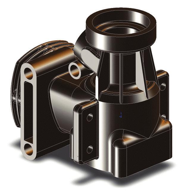
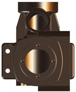
27 Exercise: Extrude Boss & Extrude Cut NOTE: In an exercise, there will be less step-by-step instruction than those in the lessons, which will give you a chance to apply what you have learned in the previous lesson to build the model on your own. 1. Dimensions are in inches, 3 decimal places. 2. Use Mid-Plane end condition for the Base feature. 3. The part is symmetrical about the Front plane. 4. Use the instructions on the following pages if needed. Origin 4X.060 X


28 1. Starting with the base sketch: - Select the Front plane and open a new sketch. - Starting at the top left corner, using the line command, sketch the profile below. Origin Parallel - Add the dimensions shown. - Add the Parallel relation to fully define the sketch. - Extrude Boss/Base with Mid Plane and in depth. 3-26


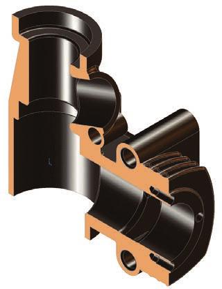
29 2. Adding the through holes: - Select the face as indicated and click the Normal-To button. - This command rotates the part normal to the screen. Select this face and click the Normal-To button - The hot-key for this command is Ctrl Open a new sketch and draw a centerline that starts from the origin point. - Sketch 2 circles on either side of the centerline. - Add the diameter and location dimensions shown. Push Escape when done. Both circles are Symmetric about the Centerline - Hold the Control key and select both circles and the centerline, then click the Symmetric relation on the properties tree. 3-27


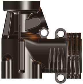
30 - Create an extruded cut using the Through- All condition. 3. Adding the upper cut: - Select the upper face and click the Sketch pencil to open a new sketch. - Sketch a centerline that starts at the Origin. - Sketch a rectangle as shown. Both lines are Symmetric about the Centerline - Add the dimensions and relations as indicated. - Create an extruded cut using the Up-To-Vertex condition (up-to-surface also works). - Select the Vertex indicated. Select Vertex - Click OK. 3-28


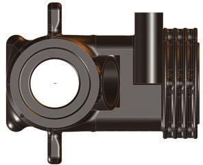
31 4. Adding the lower cut: - Select the lower face of the part and open a new sketch. - Sketch a rectangle on this face. - Add a Collinear and an Equal relations to the lines and the edges as noted. - Extrude a cut using the Through All condition. The line is Collinear and Equal with the edge on both sides. 5. Adding a chamfer: - Click Chamfer under the Fillet button. Select 4 edges - Enter.060 for depth. - Select the 4 circular edges of the 2 holes. - Click OK. 6. Saving your work: - Click File / Save As. - Enter Extrudes_Exe1 for the file name. - Select a location to save the file. - Click Save. 3-29


32 Using the Search Commands: The Search Commands lets you find and run commands from SolidWorks Search or locate commands in the user interface. These features make it easy to find and run any SolidWorks command: - The results are filtered as you type and typically find the command you need within a few keystrokes. - When you run a command from the results list for a query, Search Commands remembers that command and places it at the top of the results list when you type the same query again. - Search shortcuts lets you assign simple and familiar keystroke sequences to Commands you use regularly. 3-30

33 1. Search Commands in Feature Mode: - The example below shows how you might use Search Commands to find and run the Lasso Selection command in the Feature Mode. - With the part still open, start typing the command Lasso Selection in Search Commands. As soon as you type the first few letters of the word Lasso, the results list displays only those commands that include the character sequence "lasso", and Lasso Selection appears near the top of the results list. - Click Show Command Location, a red arrow indicates the command in the user interface. 3-31

34 2. Search Commands in Sketch Mode: - The example below shows how you might use Search Commands to find and run the Dynamic Mirror command in the Sketch Mode. - Using the same part, open a new sketch on the side face of the model as noted. Sketch face - Start typing the command Dynamic Mirror in Search Commands. As soon as you type the first few letters of the word Dynamic, the results list displays only those commands that include the character sequence "dyna", and Dynamic command appears near the top of the results list. 3-32


35 - Click Show Command Location, a red arrow indicates the command in the user interface. - Additionally, a Search Shortcut can be assigned to any command to help find it more quickly (see Customize Keyboard in the SolidWorks Help for more info): 1. Click Tools / Customize, and select the Keyboard tab. 2. Navigate to the command to which you want to assign a search shortcut. 3. In the Search Shortcut column for the command, type the shortcut letter you want to use, then click OK. - Save and close all documents. 3-33

36 SolidWorks 2015 l Basic Tools l Basic Solid Modeling 3-34
SOLIDWORKS 2016 Advanced Techniques
 SOLIDWORKS 2016 Advanced Techniques Mastering Parts, Surfaces, Sheet Metal, SimulationXpress, Top Down Assemblies, Core & Cavity Molds Paul Tran CSWE, CSWI SDC PUBLICATIONS Better Textbooks. Lower Prices.
Beginner s Guide to SolidWorks Alejandro Reyes, MSME Certified SolidWorks Professional and Instructor SDC PUBLICATIONS
 Beginner s Guide to SolidWorks 2008 Alejandro Reyes, MSME Certified SolidWorks Professional and Instructor SDC PUBLICATIONS Schroff Development Corporation www.schroff.com www.schroff-europe.com Part Modeling
Digital Camera Exercise
 Commands Used New Part This lesson includes Sketching, Extruded Boss/Base, Extruded Cut, Fillet, Chamfer and Text. Click File, New on the standard toolbar. Select Part from the New SolidWorks Document
Engineering Technology
 Engineering Technology Introduction to Parametric Modelling Engineering Technology 1 See Saw Exercise Part 1 Base Commands used New Part This lesson includes Sketching, Extruded Boss/Base, Hole Wizard,
AEROPLANE. Create a New Folder in your chosen location called Aeroplane. The four parts that make up the project will be saved here.
 AEROPLANE Prerequisite Knowledge Previous knowledge of the following commands is required to complete this lesson. Sketching (Line, Rectangle, Arc, Add Relations, Dimensioning), Extrude, Assemblies and
Shaft Hanger - SolidWorks
 ME-430 INTRODUCTION TO COMPUTER AIDED DESIGN Shaft Hanger - SolidWorks BY: DR. HERLI SURJANHATA ASSIGNMENT Submit TWO isometric views of the Shaft Hanger with your report, 1. Shaded view of the trimetric
Engineering & Computer Graphics Workbook Using SolidWorks 2014
 Engineering & Computer Graphics Workbook Using SolidWorks 2014 Ronald E. Barr Thomas J. Krueger Davor Juricic SDC PUBLICATIONS Better Textbooks. Lower Prices. www.sdcpublications.com Powered by TCPDF (www.tcpdf.org)
Lesson 6 2D Sketch Panel Tools
 Lesson 6 2D Sketch Panel Tools Inventor s Sketch Tool Bar contains tools for creating the basic geometry to create features and parts. On the surface, the Geometry tools look fairly standard: line, circle,
Introducing SolidWorks
 Introducing SolidWorks SAAST Robotics 2008 SolidWorks Software Visually-based 3-D Mechanical design software Engineers and Designers use it to: Quickly sketch out ideas Experiment with features, dimensions
Engineering & Computer Graphics Workbook Using SOLIDWORKS
 Engineering & Computer Graphics Workbook Using SOLIDWORKS 2017 Ronald E. Barr Thomas J. Krueger Davor Juricic SDC PUBLICATIONS Better Textbooks. Lower Prices. www.sdcpublications.com Powered by TCPDF (www.tcpdf.org)
Introduction to 3D CAD with SolidWorks. Jianan Li
 Introduction to 3D CAD with SolidWorks Jianan Li Create a New Part The first time you launch SolidWorks, it asks you to set the default units and dimension standard. Make sure you have IPS and ANSI selected,
Toothbrush Holder. A drawing of the sheet metal part will also be created.
 Prerequisite Knowledge Previous knowledge of the following commands is required to complete this lesson; Sketch (Line, Centerline, Circle, Add Relations, Smart Dimension,), Extrude Boss/Base, and Edit
SolidWorks 95 User s Guide
 SolidWorks 95 User s Guide Disclaimer: The following User Guide was extracted from SolidWorks 95 Help files and was not originally distributed in this format. All content 1995, SolidWorks Corporation Contents
Engineering Design. with SolidWorks A Step-by-Step Project Based Approach Utilizing 3D Solid Modeling
 INSIDE: MultiMedia CD An audio/visual presentation of the tutorial projects Engineering Design with SolidWorks 2010 A Step-by-Step Project Based Approach Utilizing 3D Solid Modeling Introductory Level
1. Open the Feature Modeling demo part file on the EEIC website. Ask student about which constraints needed to Fully Define.
 BLUE boxed notes are intended as aids to the lecturer RED boxed notes are comments that the lecturer could make Control + Click HERE to view enlarged IMAGE and Construction Strategy he following set of
SolidWorks 2005 Tutorial. and MultiMedia CD. A Step-by-step Project Based Approach Utilizing 3D Solid Modeling
 INSIDE: MultiMedia CD An audio/visual presentation of the tutorial projects SolidWorks 2005 Tutorial and MultiMedia CD A Step-by-step Project Based Approach Utilizing 3D Solid Modeling David C. Planchard
Certified SOLIDWORKS Professional Advanced Preparation Materials
 Includes Preparation for Five Advanced Certification Exams Certified SOLIDWORKS Professional Advanced Preparation Materials Sheet Metal, Weldments, Surfacing, Mold Tools and Drawing Tools SOLIDWORKS 2016
SDC. SolidWorks Tutorial 2001Plus. A Competency Project Based Approach Utilizing 3D Solid Modeling. David C. Planchard & Marie P.
 2001Plus A Competency Project Based Approach Utilizing 3D Solid Modeling David C. Planchard & Marie P. Planchard SDC PUBLICATIONS www.schroff.com www.schroff-europe.com Project 2 Below are the desired
Hydro Hull. Chapter 21. Boat. A. Save as "HYDRO". Step 1. Open your HULL MID PLANE file (Chapter 2).
.") Chapter 21 Boat Hydro Hull A. Save as "HYDRO". Step 1. Open your HULL MID PLANE file (Chapter 2). Step 2. Click File Menu > Save As. Step 3. Key-in HYDRO for the filename and press ENTER. B. Delete Loft1,
Chapter 21 Boat Hydro Hull A. Save as "HYDRO". Step 1. Open your HULL MID PLANE file (Chapter 2). Step 2. Click File Menu > Save As. Step 3. Key-in HYDRO for the filename and press ENTER. B. Delete Loft1,
Introduction to Sheet Metal Features SolidWorks 2009
 SolidWorks 2009 Table of Contents Introduction to Sheet Metal Features Base Flange Method Magazine File.. 3 Envelopment & Development of Surfaces.. 14 Development of Transition Pieces.. 23 Conversion to
Modeling an Airframe Tutorial
 EAA SOLIDWORKS University p 1/11 Difficulty: Intermediate Time: 1 hour As an Intermediate Tutorial, it is assumed that you have completed the Quick Start Tutorial and know how to sketch in 2D and 3D. If
Lesson 10: Loft Features
 10 Goals of This Lesson Your students will be able to create the following part: profiles chisel This lesson plan corresponds to the Loft Features chapter of SolidWorks Getting Started. SolidWorks Student
SolidWorks Design & Technology
 SolidWorks Design & Technology Training Course at PHSG Ex 5. Lego man Working with part files 8mm At first glance the Lego man looks complicated but I hope you will see that if you approach a project one
Part 8: The Front Cover
 Part 8: The Front Cover 4 Earpiece cuts and housing Lens cut and housing Microphone cut and housing The front cover is similar to the back cover in that it is a shelled protrusion with screw posts extruding
Advance Dimensioning and Base Feature Options
 Chapter 4 Advance Dimensioning and Base Feature Options Learning Objectives After completing this chapter you will be able to: Dimension the sketch using the autodimension sketch tool. Dimension the sketch
Engineering Design with SolidWorks A Step-by-Step Project Based Approach Utilizing 3D Solid Modeling. David C. Planchard & Marie P.
 Engineering Design with SolidWorks 2003 A Step-by-Step Project Based Approach Utilizing 3D Solid Modeling David C. Planchard & Marie P. Planchard SDC PUBLICATIONS www.schroff.com www.schroff-europe.com
Table of Contents. Lesson 1 Getting Started
 NX Lesson 1 Getting Started Pre-reqs/Technical Skills Basic computer use Expectations Read lesson material Implement steps in software while reading through lesson material Complete quiz on Blackboard
Modeling Basic Mechanical Components #1 Tie-Wrap Clip
 Modeling Basic Mechanical Components #1 Tie-Wrap Clip This tutorial is about modeling simple and basic mechanical components with 3D Mechanical CAD programs, specifically one called Alibre Xpress, a freely
Copyrighted. Material. Copyrighted. Material. Copyrighted. Material. Copyrighted. Material
 ENGINEERING & COMPUTER GRAPHICS WORKBOOK Using SolidWorks 2008 Ronald E. Barr Thomas J. Krueger Theodore A. Aanstoos Davor Juricic SDC PUBLICATIONS Schroff Development Corporation www.schroff.com Better
Introduction to Circular Pattern Flower Pot
 Prerequisite Knowledge Previous knowledge of the sketching commands Line, Circle, Add Relations, Smart Dimension is required to complete this lesson. Previous examples of Revolved Boss/Base, Cut Extrude,
SolidWorks Navigation
 SolidWorks Basics SolidWorks Navigation Command Bar Feature Tree Model Window Simple Box Select the Front plane Create a new sketch Create a Center Rectangle from the origin Smart Dimension the length
Starting a 3D Modeling Part File
 1 How to Create a 3D Model and Corresponding 2D Drawing with Dimensions, GDT (Geometric Dimensioning and Tolerance) Symbols and Title Block in SolidWorks 2013-2014 By Edward Locke This tutorial will introduce
Clock Exercise (Inserting Planes)
") Clock Exercise (Inserting Planes) Prerequisite Knowledge To complete this exercise you will need to be familiar with Sketching, Applying relations, Extrude Boss/ Base, Extrude cut, Applying Textures, Renaming
Clock Exercise (Inserting Planes) Prerequisite Knowledge To complete this exercise you will need to be familiar with Sketching, Applying relations, Extrude Boss/ Base, Extrude cut, Applying Textures, Renaming
SOLIDWORKS 2018 Basic Tools
 SOLIDWORKS 2018 Basic Tools Getting Started with Parts, Assemblies and Drawings Paul Tran CSWE, CSWI SDC PUBLICATIONS Better Textbooks. Lower Prices. www.sdcpublications.com Powered by TCPDF (www.tcpdf.org)
< Then click on this icon on the vertical tool bar that pops up on the left side.
 Pipe Cavity Tutorial Introduction The CADMAX Solid Master Tutorial is a great way to learn about the benefits of feature-based parametric solid modeling with CADMAX. We have assembled several typical parts
Below are the desired outcomes and usage competencies based on the completion of Project 4.
 Engineering Design with SolidWorks Project 4 Below are the desired outcomes and usage competencies based on the completion of Project 4. Project Desired Outcomes: An understanding of the customer s requirements
Introduction to CATIA V5
 Introduction to CATIA V5 Release 17 (A Hands-On Tutorial Approach) Kirstie Plantenberg University of Detroit Mercy SDC PUBLICATIONS Schroff Development Corporation www.schroff.com Better Textbooks. Lower
Copyrighted. Material. Copyrighted. Material. Copyrighted. Material. Copyrighted. Material
 ENGINEERING & COMPUTER GRAPHICS WORKBOOK Using SolidWorks 2005 Ronald E. Barr Thomas J. Krueger Theodore A. Aanstoos Davor Juricic SDC PUBLICATIONS Schroff Development Corporation www.schroff.com www.schroff-europe.com
Introduction to Autodesk Inventor for F1 in Schools (Australian Version)
") Introduction to Autodesk Inventor for F1 in Schools (Australian Version) F1 in Schools race car In this course you will be introduced to Autodesk Inventor, which is the centerpiece of Autodesk s Digital
Introduction to Autodesk Inventor for F1 in Schools (Australian Version) F1 in Schools race car In this course you will be introduced to Autodesk Inventor, which is the centerpiece of Autodesk s Digital
Introduction to Revolve - A Glass
 Introduction to Revolve - A Glass Design & Communication Graphics 1 Object Analysis sheet Design & Communication Graphics 2 Prerequisite Knowledge Previous knowledge of the following commands are required
Conquering the Rubicon
 Autodesk Inventor R10 Fundamentals: Conquering the Rubicon Elise Moss SDC PUBLICATIONS Schroff Development Corporation www.schroff.com www.schroff-europe.com Schroff Development Corporation P.O. Box 1334
AutoCAD 2018 Fundamentals
 Autodesk AutoCAD 2018 Fundamentals Elise Moss SDC PUBLICATIONS Better Textbooks. Lower Prices. www.sdcpublications.com Powered by TCPDF (www.tcpdf.org) Visit the following websites to learn more about
Chair. Bottom Rail. on the Command Manager. on the Weldments toolbar.
 Chapter 2 Chair Bottom Rail A. Weldments Toolbar. Step 1. Click File Menu > New, click Part and OK. Step 2. Right click Sketch on the Command Manager toolbar and select Weldments, Fig. 1. Step 3. Click
Evaluation Chapter by CADArtifex
 The premium provider of learning products and solutions www.cadartifex.com EVALUATION CHAPTER 2 Drawing Sketches with SOLIDWORKS In this chapter: Invoking the Part Modeling Environment Invoking the Sketching
10/14/2010. Chevy Malibu. Vehicle Design with Solidworks. Start SolidWorks Create a New SolidWorks Document. Miles, Rowardo B
 Chevy Malibu Vehicle Design with Solidworks Start SolidWorks Create a New SolidWorks Document Miles, Rowardo B 1 Click: Part and then OK Now you are ready to make a Part. 2 Right Toolbar: Document Properties:
Bottom Rail. Chapter 2. Chair. A. Weldments Toolbar. Step 1. Click File Menu > New, click Part and OK. B. 3D Sketch.
 Chapter 2 Chair Bottom Rail A. Weldments Toolbar. Step 1. Click File Menu > New, click Part and OK. Step 2. Right click Sketch on the Command Manager toolbar and select Weldments, Fig. 1. Step 3. Click
From the above fig. After sketching the path and profile select the sweep command First select the profile from property manager tree And then select
 Chapter 5 In sweep command there is a) Two sketch profiles b) Two path c) One sketch profile and one path The sweep profile is used to create threads springs circular things and difficult geometry. For
SOLIDWORKS 2017 Basic Tools
 SOLIDWORKS 2017 Basic Tools Getting Started with Parts, Assemblies and Drawings Paul Tran CSWE, CSWI SDC PUBLICATIONS Better Textbooks. Lower Prices. www.sdcpublications.com Powered by TCPDF (www.tcpdf.org)
Computer Aided Design Module 2. Lesson Toblerone Bar
 Computer Aided Design Module 2 Lesson Toblerone Bar Lesson? Toblerone Bar New Commands used: Polygon, Add Relations, Smart Dimension, Extrude Boss/Base (Mid Plane), Fillet, Line, Extrude-Cut, Linear Pattern
Lesson 4 Extrusions OBJECTIVES. Extrusions
 Lesson 4 Extrusions Figure 4.1 Clamp OBJECTIVES Create a feature using an Extruded protrusion Understand Setup and Environment settings Define and set a Material type Create and use Datum features Sketch
SOLIDWORKS 2015 and Engineering Graphics
 SOLIDWORKS 2015 and Engineering Graphics An Integrated Approach Randy H. Shih SDC PUBLICATIONS Better Textbooks. Lower Prices. www.sdcpublications.com Powered by TCPDF (www.tcpdf.org) Visit the following
ME Week 2 Project 2 Flange Manifold Part
 1 Project 2 - Flange Manifold Part 1.1 Instructions This project focuses on additional sketching methods and sketching commands. Revolve and Work features are also introduced. The part being modeled is
Lesson 4 Holes and Rounds
 Lesson 4 Holes and Rounds 111 Figure 4.1 Breaker OBJECTIVES Sketch arcs in sections Create a straight hole through a part Complete a Sketched hole Understand the Hole Tool Use Info to extract information
SolidWorks Part I - Basic Tools SDC. Includes. Parts, Assemblies and Drawings. Paul Tran CSWE, CSWI
 SolidWorks 2015 Part I - Basic Tools Includes CSWA Preparation Material Parts, Assemblies and Drawings Paul Tran CSWE, CSWI SDC PUBLICATIONS Better Textbooks. Lower Prices. www.sdcpublications.com Powered
CREO.1 MODELING A BELT WHEEL
 CREO.1 MODELING A BELT WHEEL Figure 1: A belt wheel modeled in this exercise. Learning Targets In this exercise you will learn: Using symmetry when sketching Using pattern to copy features Using RMB when
SolidWorks 2014 Part I - Basic Tools
 SolidWorks 2014 Part I - Basic Tools Parts, Assemblies and Drawings Paul Tran CSWE, CSWI SDC PUBLICATIONS Better Textbooks. Lower Prices. www.sdcpublications.com Powered by TCPDF (www.tcpdf.org) Visit
Lab 3 Introduction to SolidWorks I Silas Bernardoni 10/9/2008
 1 Introduction This lab is designed to provide you with basic skills when using the 3D modeling program SolidWorks. You will learn how to build parts, assemblies and drawings. You will be given a physical
1. Create a 2D sketch 2. Create geometry in a sketch 3. Use constraints to position geometry 4. Use dimensions to set the size of geometry
 2.1: Sketching Many features that you create in Fusion 360 start with a 2D sketch. In order to create intelligent and predictable designs, a good understanding of how to create sketches and how to apply
Creo Revolve Tutorial
 Creo Revolve Tutorial Setup 1. Open Creo Parametric Note: Refer back to the Creo Extrude Tutorial for references and screen shots of the Creo layout 2. Set Working Directory a. From the Model Tree navigate
SolidWorks 2013 Part I - Basic Tools
 SolidWorks 2013 Part I - Basic Tools Parts, Assemblies and Drawings Paul Tran CSWE, CSWI Supplemental Files SDC PUBLICATIONS Schroff Development Corporation Better Textbooks. Lower Prices. www.sdcpublications.com
Inventor-Parts-Tutorial By: Dor Ashur
 Inventor-Parts-Tutorial By: Dor Ashur For Assignment: http://www.maelabs.ucsd.edu/mae3/assignments/cad/inventor_parts.pdf Open Autodesk Inventor: Start-> All Programs -> Autodesk -> Autodesk Inventor 2010
Sash Clamp. Sash Clamp SW 2015 Design & Communication Graphics Page 1.
 Sash Clamp 1 Introduction: The Sash clamp consists of nine parts. In creating the clamp we will be looking at the improvements made by SolidWorks in linear patterns, adding threads and in assembling the
SolidWorks Reference Geometry
 SolidWorks Reference Geometry IDeATe Laser Micro Part 2 Dave Touretzky and Susan Finger 1. Symmetry and Reference Geometry Today, you ll make this part bear-like face and then cut it on the laser cutter:
Chapter 2. Drawing Sketches for Solid Models. Learning Objectives
 Chapter 2 Drawing Sketches for Solid Models Learning Objectives After completing this chapter, you will be able to: Start a new template file to draw sketches. Set up the sketching environment. Use various
and Engineering Graphics
 SOLIDWORKS 2018 and Engineering Graphics An Integrated Approach Randy H. Shih SDC PUBLICATIONS Better Textbooks. Lower Prices. www.sdcpublications.com Powered by TCPDF (www.tcpdf.org) Visit the following
AutoCAD 2020 Fundamentals
 Autodesk AutoCAD 2020 Fundamentals ELISE MOSS Autodesk Certified Instructor SDC PUBLICATIONS Better Textbooks. Lower Prices. www.sdcpublications.com Powered by TCPDF (www.tcpdf.org) Visit the following
Product Modelling in Solid Works
 Product Modelling in Solid Works In the following exercise you will use solid works to construct the computer mouse shown opposite. In this exercise you will use a number of advanced features to achieve
Using Siemens NX 11 Software. The connecting rod
 Using Siemens NX 11 Software The connecting rod Based on a Catia tutorial written by Loïc Stefanski. At the end of this manual, you should obtain the following part: 1 Introduction. Start NX 11 and open
for Solidworks TRAINING GUIDE LESSON-9-CAD
 for Solidworks TRAINING GUIDE LESSON-9-CAD Mastercam for SolidWorks Training Guide Objectives You will create the geometry for SolidWorks-Lesson-9 using SolidWorks 3D CAD software. You will be working
Student + Instructor:
 BLUE boxed notes are intended as aids to the lecturer RED boxed notes are comments that the lecturer could make Show 01 Solid Modeling Intro slides quickly. SolidWorks Layout slides are on EEIC for reference
Official Guide to Certified SolidWorks Associate Exams: CSWA, CSDA, CSWSA-FEA
 Official Guide to Certified SolidWorks Associate Exams: CSWA, CSDA, CSWSA-FEA SolidWorks 2012-2015 An authorized CSWA preparation exam guide with additional information on the CSDA and CSWSA-FEA exams
Beginner s Guide to SolidWorks Level I
 Beginner s Guide to SolidWorks 2014 - Level I Parts, Assemblies, Drawings, PhotoView 360 and Simulation Xpress Videos Now includes SolidWorks training videos Alejandro Reyes MSME, CSWP, CSWI Multimedia
Quick Start for Autodesk Inventor
 Quick Start for Autodesk Inventor Autodesk Inventor Professional is a 3D mechanical design tool with powerful solid modeling capabilities and an intuitive interface. In this lesson, you use a typical workflow
SolidWorks Training. Introductory course for staff and students from the School of Physics and Astronomy
 SolidWorks Training Introductory course for staff and students from the School of Physics and Astronomy i) Introductory presentation SolidWorks Training ii) The SolidWorks GUI The SolidWorks Graphical
Siemens NX11 tutorials. The angled part
 Siemens NX11 tutorials The angled part Adaptation to NX 11 from notes from a seminar Drive-to-trial organized by IBM and GDTech. This tutorial will help you design the mechanical presented in the figure
Revit Structure 2014 Basics
 Revit Structure 2014 Basics Framing and Documentation Elise Moss Authorized Author SDC P U B L I C AT I O N S Better Textbooks. Lower Prices. www.sdcpublications.com Powered by TCPDF (www.tcpdf.org) Visit
SolidWorks Tutorial 1. Axis
 SolidWorks Tutorial 1 Axis Axis This first exercise provides an introduction to SolidWorks software. First, we will design and draw a simple part: an axis with different diameters. You will learn how to
Alternatively, the solid section can be made with open line sketch and adding thickness by Thicken Sketch.
 Sketcher All feature creation begins with two-dimensional drawing in the sketcher and then adding the third dimension in some way. The sketcher has many menus to help create various types of sketches.
Module 2: Radial-Line Sheet-Metal 3D Modeling and 2D Pattern Development: Right Cone (Regular, Frustum, and Truncated)
") Inventor (5) Module 2: 2-1 Module 2: Radial-Line Sheet-Metal 3D Modeling and 2D Pattern Development: Right Cone (Regular, Frustum, and Truncated) In this tutorial, we will learn how to build a 3D model
Inventor (5) Module 2: 2-1 Module 2: Radial-Line Sheet-Metal 3D Modeling and 2D Pattern Development: Right Cone (Regular, Frustum, and Truncated) In this tutorial, we will learn how to build a 3D model
DEPARTMENT OF MECHANICAL AND INDUSTRIAL ENGINEERING NORTHEASTERN UNIVERSITY
 DEPARTMENT OF MECHANICAL AND INDUSTRIAL ENGINEERING NORTHEASTERN UNIVERSITY CAPSULE PROGRAM Funded by NSF grant #0833636 Tutorial 02 3D Part Modeling SolidWorks 2010 Copyright 2010 Prof. Zeid 3D Part Modeling
Part Design. Sketcher - Basic 1 13,0600,1488,1586(SP6)
") Part Design Sketcher - Basic 1 13,0600,1488,1586(SP6) In this exercise, we will learn the foundation of the Sketcher and its basic functions. The Sketcher is a tool used to create two-dimensional (2D)
Part Design Sketcher - Basic 1 13,0600,1488,1586(SP6) In this exercise, we will learn the foundation of the Sketcher and its basic functions. The Sketcher is a tool used to create two-dimensional (2D)
g. Click once on the left vertical line of the rectangle.
 This drawing will require you to a model of a truck as a Solidworks Part. Please be sure to read the directions carefully before constructing the truck in Solidworks. Before submitting you will be required
Autodesk AutoCAD 2013 Fundamentals
 Autodesk AutoCAD 2013 Fundamentals Elise Moss SDC P U B L I C AT I O N S Schroff Development Corporation Better Textbooks. Lower Prices. www.sdcpublications.com Visit the following websites to learn more
Datum Tutorial Part: Cutter
 Datum Tutorial Part: Cutter Objective: Learn to apply Datums in different ways Directions 1. Datum Axis Creation a. First we need to create a center axis for the cutter b. Model Tab > Datum > Select Axis
Autodesk Inventor Module 17 Angles
 Inventor Self-paced ecourse Autodesk Inventor Module 17 Angles Learning Outcomes When you have completed this module, you will be able to: 1 Describe drawing inclined lines, aligned and angular dimensions,
Module 1C: Adding Dovetail Seams to Curved Edges on A Flat Sheet-Metal Piece
 1 Module 1C: Adding Dovetail Seams to Curved Edges on A Flat Sheet-Metal Piece In this Module, we will explore the method of adding dovetail seams to curved edges such as the circumferential edge of a
Revit Structure 2013 Basics
 Revit Structure 2013 Basics Framing and Documentation Elise Moss Supplemental Files SDC P U B L I C AT I O N S Schroff Development Corporation Better Textbooks. Lower Prices. www.sdcpublications.com Tutorial
Alibre Design Tutorial: Loft, Extrude, & Revolve Cut Loft-Tube-1
 Alibre Design Tutorial: Loft, Extrude, & Revolve Cut Loft-Tube-1 Part Tutorial Exercise 5: Loft-Tube-1 [Complete] In this Exercise, We will set System Parameters first, then part options. Then, in sketch
FUSION 360: SKETCHING FOR MAKERS
 FUSION 360: SKETCHING FOR MAKERS LaDeana Dockery 2017 MAKEICT Wichita, KS 1 Table of Contents Interface... 1 File Operations... 1 Opening Existing Models... 1 Mouse Navigation... 1 Preferences... 2 Navigation
Module 1G: Creating a Circle-Based Cylindrical Sheet-metal Lateral Piece with an Overlaying Lateral Edge Seam And Dove-Tail Seams on the Top Edge
 Inventor (10) Module 1G: 1G- 1 Module 1G: Creating a Circle-Based Cylindrical Sheet-metal Lateral Piece with an Overlaying Lateral Edge Seam And Dove-Tail Seams on the Top Edge In Module 1A, we have explored
Foreword. If you have any questions about these tutorials, drop your mail to
 Foreword The main objective of these tutorials is to give you a kick start using Solidworks. The approach to write this tutorial is based on what is the most important knowledge you should know and what
Introduction to SolidWorks Introduction to SolidWorks
 Introduction to SolidWorks Introduction to SolidWorks SolidWorks is a powerful 3D modeling program. The models it produces can be used in a number of ways to simulate the behaviour of a real part or assembly
Feature-Based Modeling and Optional Advanced Modeling. ENGR 1182 SolidWorks 05
 Feature-Based Modeling and Optional Advanced Modeling ENGR 1182 SolidWorks 05 Today s Objectives Feature-Based Modeling (comprised of 2 sections as shown below) 1. Breaking it down into features Creating
Understanding Projection Systems
 Understanding Projection Systems A Point: A point has no dimensions, a theoretical location that has neither length, width nor height. A point shows an exact location in space. It is important to understand
Module 1H: Creating an Ellipse-Based Cylindrical Sheet-metal Lateral Piece
 Inventor (10) Module 1H: 1H- 1 Module 1H: Creating an Ellipse-Based Cylindrical Sheet-metal Lateral Piece In this Module, we will learn how to create an ellipse-based cylindrical sheetmetal lateral piece
Revit Structure 2012 Basics:
 SUPPLEMENTAL FILES ON CD Revit Structure 2012 Basics: Framing and Documentation Elise Moss autodesk authorized publisher SDC PUBLICATIONS www.sdcpublications.com Schroff Development Corporation Structural