Computer Aided Design Module 2. Lesson Toblerone Bar
|
|
|
- Paul Russell
- 5 years ago
- Views:
Transcription
1 Computer Aided Design Module 2 Lesson Toblerone Bar


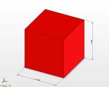
2 Lesson? Toblerone Bar New Commands used: Polygon, Add Relations, Smart Dimension, Extrude Boss/Base (Mid Plane), Fillet, Line, Extrude-Cut, Linear Pattern & Edit Color. Approach: Create Sketch Create the sketch shown on the right plane. Select Polygon from the sketch toolbar. Choose 3 as the Number of sides. Select the origin as the centre of the inscribed circle. Add Relation Smart Dimension Extruded Boss/Base Fillet Add a Horizontal Relation to the base. Fully Define the sketch using only the dimension displayed. Extrude the sketch using a Mid Plane End Condition of depth 155mm. Apply a 1mm Fillet to the top edge as shown. Adding the Notches Sketch on the Front Plane Add Relation (below) Smart Dimension Using the Line command, create the sketch on the front plane of the triangle (shown across). All relations are Automatic Relations. Add an Equal Relation to the two inclined sides. Add a Horizontal Relation between the origin and the lower vertex of the triangle. Fully Define the sketch using the dimensions displayed.


3 Extruded-Cut Extrude the sketch using Extrude-Cut. Extrude in Direction 1 using a Through All End Condition. Extrude in Direction 2 using a Through All End Condition. Fillet Apply a 1mm Fillet to the edge of the notch as shown. Linear Pattern Select Linear Pattern from the Features toolbar. Select the linear edge of the base as Direction 1. Input a Spacing of 15mm. Input 10 as the Number of Instances. Click in the Features to Pattern window. Expand the Feature Manager Design Tree. Select the Notch and the Fillet notch as the Features to Pattern. Edit Color Choose a suitable colour from the Edit Color palette.

4 Computer Aided Design Module 2 Lesson Baking Tray

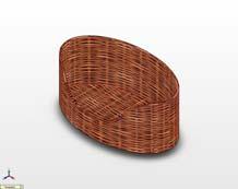
5 Lesson 1 Baking Tray Commands used: Sketch Rectangle, Sketch Fillet, Circle, Smart dimension, Extrude Boss/Base, Linear Pattern, Shell, Fillet & Edit Material Approach to Lesson: Create sketch top of tray Create the sketch on the Top Plane using the Rectangle sketch command. Use Sketch Fillet to apply a fillet of 40mm to the corners Use Smart Dimension to dimension the sketch Extruded Boss/Base Extrude the sketch using Extruded Boss/Base Select Blind as the end condition and a distance of 6mm. Rename the feature as Top of tray. Create sketch for cup Select the top face of the tray as the plane for this sketch Sketch with Circle and Smart Dimension Extruded Boss/Base for Cup Extrude the sketch using Blind as the end


6 condition and a distance of 20mm. Select a draft angle of 15. Rename the feature as Cup Apply Fillet to Cup Apply a 2mm fillet to the base edge of the cup using the Fillet feature Rename the feature as Fillet at base of cup. Linear Pattern of Cup Use Linear Pattern to create the other cups using the criteria shown below. patterned Apply fillet edge of Tray top Rename feature as Cup Apply a 6mm fillet to the


7 bottom edge of the top of the tray. Rename the feature as 6mm edge fillet. Shell the tray Apply a wall thickness of 1.5mm and remove the top face Rename the feature as Tray shelled. Fillet top surface Apply a 2mm fillet to the top surface of the tray. Rename the feature as Top surface fillet Full round fillet Apply a full round fillet to the top edge of the baking tray.

8 Rename as Full round fillet. Edit Material Apply a Chrome Stainless Steel finish using Edit Material
9
10
11 Computer Aided Design Module 1 Lesson Bench Hook
12

13 Computer Aided Design Module 1 Lesson Desk Calendar
14

15 Computer Aided Design Module 1 Lesson Doll s Chair

16 Lesson 1 Doll s Chair Commands used: Sketch Rectangle, Circle, Add Relations, Trim, Smart dimension,,extrude Boss/Base, Extruded Cut, Fillet & Edit Material Approach to Lesson: Create sketch for seat Create the sketch on the Right Plane using the Rectangle sketch command. Smart Dimension Fully define the sketch using the given dimensions and confirm sketch. Extruded Boss/Base Extrude the sketch using Extruded Boss/Base Select Mid-Plane the end condition and a distance of 250mm. Rename the feature as Seat. Create sketch for side Select the end face of the seat of the as the plane for this sketch Sketch rectangle, circles and lines as shown. (Alternatively you can draw the outline of the side using the line command). Add the appropriate relations as indicated Use the Trim Entities command to remove lines and arcs. Use Smart Dimension to full define the sketch as shown.

17 Extruded Boss/Base Extrude the sketch using Blind as the end condition and a distance of 16mm. Rename the feature as Right side. Mirror Feature Mirror the right hand side of the chair in the Right Plane to create the left side Rename the feature to Right side mirrored. Create sketch for back Select the back surface of the seat/sides as the plane to create the sketch. Use the Centreline, Rectangle, Circle and Trim commands to draw the sketch.
18 Smart Dimension as indicated. Extruded Boss/Base Extrude the sketch using Blind as the end condition and a distance of 16mm. Rename the feature as Back. Create sketch for Rail Select the front surface of the either side as the plane to create the sketch. Use the Centreline, Rectangle, Circle and Trim commands to draw the sketch. Smart Dimension as indicated. Extruded Boss/Base Extrude the sketch using Blind as the end condition and a distance of 16mm. Rename the feature as Front Rail. Create sketch for Heart Shape Select the front surface of the Back as the plane to create the sketch. Use the Centreline and Line commands to draw the sketch the left hand side of the sketch.


19 Use Mirror sketch on the sketch tool to create the right hand side of the Smart Dimension as indicated Cut Extrude Fillet 1 Fillet 2 Cut Extrude using Through All as the end condition. Using Fillet, add a 60mm fillet to the selected edges of the Back and Front Rail. Add a 10mm fillet to the front corners of the seat. Edit Colour Apply a colour to the part from the Color and Optics Property Manager.
20

21 Computer Aided Design Module 1 Lesson Drawing Clip


22 Lesson 1 Drawing Clip Commands used: Line, 3 Point Arc, Add Relations, Smart dimension, Offset Entities, Extrude Boss/Base (Mid Plane End Condition), Fillet & Edit Material Approach: Create Sketch Automatic Relations Create the sketch shown on the Front Plane. Use 3 Point Arc to generate the curve Ensure all Automatic Relations are included. Added Relations Smart Dimension Add a Vertical Relation between the arc endpoint and the end of the horizontal line. Fully Define the sketch using only the given dimensions Offset Entities Using Offset Entities create a 1.25mm offset to the outside. Close the ends using the Line command. Extruded Boss/Base Extrude the sketch using Extruded Boss/Base and a Mid-Plane End Condition. Fillet Using Fillet, add a 6.5mm fillet to the selected edges. Edit Material Apply a Chrome Stainless Steel finish using Edit Material. (Use RealView in Advanced Graphics) Discussion Points Inclusion of Automatic Relations. Added Relations as opposed to dimensioning Influence of appropriate End Conditions Explain the emboldened terms

23 Computer Aided Design Module 2 Lesson Sellotape Holder


 Edit Material Edit Colour Discussion Points Apply a Perspex Acrylic Sheet finish using Edit Material.")
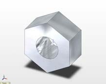
24 Lesson 2 Sellotape Holder New Commands used: Circle, Tangent Arc, Trim Entities, Extrude Boss/Base (Up to Surface), Shell & Edit Color. Approach: Create Sketch Add Relation Trim Entities Smart Dimension Extruded Boss/Base Create the sketch shown on the front plane All relations are Automatic Relations (Note the Origin position) Add a Horizontal Relation between the centre of the Circle and the centre of the Tangent Arc. Remove the unwanted portion of the circle using Trim Entities. Fully Define the sketch using only the dimensions displayed. Extrude the sketch using a Blind End Condition and a depth of 23mm Fillet Shell Sketch on a face Extruded Boss/Base Apply a Fillet to the corners shown. Shell the part to a 1mm wall thickness. Remove the selected faces shown opposite Create the sketch shown on the new face of the shelled part. Ensure that the centre of the circle is coincident with the origin. Use Offset to generate the inner circle. Extrude the sketch using an Up To Surface End Condition. (Use the 1mm front face as surface) Edit Material Edit Colour Discussion Points Apply a Perspex Acrylic Sheet finish using Edit Material. Choose a suitable colour from the Edit Color palette Positioning of the Origin Inclusion of Automatic Relations. Sketching on a Face Why Up To Surface End Condition? Explain the emboldened terms

25 SOLIDWORKS TEACHER TRAINING MANUAL Created By Solid Solutions Ireland
26 Table of Contents Page 1.0 Introduction What is SolidWorks? Create a Part Create a drawing Create an Assembly Exercises 44 2
27 1.0 Introduction 3
28 1.0 Introduction As your first step to mastering the use of solid works we are going to review the user interface or the SolidWorks window (See Fig 1.0 page 2). To begin, using the left mouse button double click on the SolidWorks icon on the PC desktop screen to open the program. If there is no icon visible the program can be started through Start - All Programs SolidWorks You can access commands in SolidWorks using menus, toolbars and the mouse. The SolidWorks interface is dynamic in that different toolbars and menus appear depending on the active document type. 1.1 Document Windows The format of the SolidWorks window reflects that of windows itself. The same is true for any SolidWorks document. Once opened a document appears split into two panels. The right is the graphics window, where your model or drawing appears. You can create and manipulate the document in the graphics window. The left panel contains the following SolidWorks document windows: FeatureManager design tree: Similar to the windows explorer tree it lists the structure of the part, assembly or drawing. PropertyManager: Appears in the left panel when you select many of the SolidWorks commands such as sketches, fillet features and so on. The PropertyManager displays selection icons to enter relevant command options and boxes/fields to enable the user to enter relevant design and data parameters. ConfigurationManager: Appears in place of the FeatureManager design tree. Helps create, select and view multiple configurations (variations of parts and assemblies in a single document). 4
: 1.")
29 1.2 The SolidWorks window Figure 1.0: SolidWorks display commands relevant to the document type The Main elements of the SolidWorks user interface are as follows (see Figure 1.0 for the corresponding item numbers): 1. Title bar: Displays the name of the active document and active document window with a blue (default color) title bar. Inactive document windows are shown with a grey title bar. If you haven t saved any changes to a document, you see a * after the document name. 2. Main Menu: A set of drop down menus (File, Edit, View, and so on) across the top of the user interface. The menu bar contents are task dependent based on the active document type. SolidWorks toolbars display these functions whereas the menu bar contains the complete set. 3. Standard toolbar: Found just beneath the main menu this toolbar is consists of a set of the most commonly used command buttons. 4. View toolbar: Features a series of commonly used command buttons that allow you to zoom, rotate and view the part in different orientations. 5. Minimize window: Shrinks the document window. 6. Maximize window: Enlarges the viewing window to full-size. 7. Close window: Closes solid works. If you have made any changes to you documents, SolidWorks prompts you to save the document. 5
30 8. Command Manager: A dynamic toolbar that lists the command buttons for the type of document you are working on. 9. FeatureManager design tree tab: Displays the FeatureManager design tree. 10. PropertyManager: Appears in the left panel when you select many of the SolidWorks commands such as sketches, fillet features and so on. The PropertyManager displays selection icons to enter relevant command options and boxes/fields to enable the user to enter relevant design and data parameters. 11. ConfigurationManager tab: Appears in place of the FeatureManager design tree. Helps create, select and view multiple configurations (variations of parts and assemblies in a single document). 12. FeatureManager design tree: Similar to the windows explorer tree it lists the structure of the part, assembly or drawing. 13. Show display pane: Expands or collapses the display pane. 14. Graphics area: Displays the part assembly or drawing. 15. Pointer: Indicates the position of the mouse and lets you select items within the user interface (not shown on Fig 1.0) 16. Tool tip: A pop up informational message about a feature or function. It appears when you hover the pointer over an object. It disappears after a few seconds (not shown on Fig 1.0). 17. Status bar: Gives more complex explanation of the selected function. 18. Status bar: Indicates whether it is a drawing, part or assembly that you are editing. 19. Quick tips help: Indicates with a question mark button whether Quick Tips is on or off. Click the icon to toggle 20. Resize window: Enables resizing (by clicking and dragging) the window if it isn t already maximized. 21. SolidWorks resources: Click to open the SolidWorks Resources tab, which contains links to resources, tutorials, tips of the day and also command buttons to open or create SolidWorks documents. 22. Design Library: Click to open the design library. Inside you see the Design Library, Toolbox and 3D Content Central each which contain many standard design elements you can drag and drop into your design. 23. File Explorer: Duplicates Windows Explorer in your computer. Lists recently opened documents and currently opened documents. You can drag documents from here into the graphics area. 6
31 1.2.1 The FeatureManager design tree On the left side of the SolidWorks document window the FeatureManager design tree provides Windows Explorer-type selection and editing access to all the entities in your active document. The type of entities the design tree is populated with varies depending on the active document type from features and sketches for part documents to drawing views for a drawing and parts/subassemblies in an assembly. Key advantages offered by the FeatureManager design tree: Shows the order in which the elements were created with the oldest at the top Links to the graphics pane Allows selection/highlighting of an object by clicking/hovering the pointer over the appropriate element in either the design tree or graphics area. Displays graphical feedback that displays feature or component characteristics: For Example if the component is suppressed, it appears in grey. Allows you to see the contents of the folders in the tree: You can click + or to maximize or minimize the folder. Gives you access to quick functions when you right click: The functions displayed will depend on the object and document type. Fig 1.1: The CommandManager The Command Manager Located just below the standard tool bar in the top left hand corner of the document window, is the CommandManager, a smart toolbar that displays the menus you need for the task at hand. The CommandManager is divided into two areas: the control area made up a selection of buttons any of which selected displays a toolbar in the toolbar area (directly to the right of the control area as shown above). For example, if you select the Features button, the Feature commands display in the toolbar area (Extruded base/boss, extruded cut and so on). The CommandManager makes efficient use of the space onscreen by embedding a number of toolbars in just one. As a result this minimizes the number of menu picks, mouse movements and overall allows the user to work faster and more efficiently. 1.3 View and Orientation A set of predefined views can be selected through the Standard view toolbar, a flyout (similar to a drop down Menu) tool bar that is embedded in the View toolbar. If you click the Standard View button in the View toolbar, you get a pull-down menu of several commands that represent standard engineering views. This enables the user to select views such as Side, Front, Top, Right and Bottom as well as perspectives: Isometric, Trimetric and Dimetric which vary in viewing Orientation The orientation section of the View toolbar offers several tools to enable the user to manually manipulate the orientation of a model. These manipulation tools include the following: Zoom to Fit: Zooms in or out so the entire model is visible. 7
32 Zoom to Area: Zooms in on a portion of the view that you select by dragging a bounding box. The centre of the box is marked with plus (+) sign. Zoom In/Out: Zooms in as you press and hold the left mouse button and drag the mouse up. Zooms out as you drag the mouse down. Zoom to Selection: Zooms to the size of a selected entity. Rotate View: Rotates the view as you press and hold the left mouse button and drag the mouse around the screen. Roll View: Rotates the view about an axis normal to the screen as you press and hold the left mouse button and drag the mouse around the screen. Pan View: Scrolls the view so the model moves as you drag the mouse Display Modes The third section of the View toolbar offers the following display modes for model and drawing view in drawing documents. These tools include the following: Shaded Shaded with Edges Hidden Lines Removed Hidden Lines Visible Wireframe (Displays all edges of the model) Section View Shaded Shaded with Hidden Lines Hidden Lines Wireframe Edges Removed Visible Fig 1.2: Display Modes 8


33 Fig 1.3: Section View and PropertyManager 1.4 Control Mouse buttons SolidWorks uses three mouse buttons to access features, select objects and perform tasks: Left: Selects menu items, entities in the graphics area, and objects in the FeatureManager design tree. To select an entity click on the entity in the graphics window or in the feature manager design tree. Selected objects become highlighted in both the graphics area and FeatureManager design tree. To select multiple entities hold down the Ctrl button while continuing to click on the objects to be selected. To select a group of objects hold down the mouse button and drag a window around the objects. To deselect all objects click anywhere in the document window outside the part or assembly. Right: Displays context sensitive options and shortcut menus. Middle: Rotate: Pan: Zoom: Hold down button and move mouse. To rotate about a vertex edge or axis (other than the origin) click the middle mouse button on the geometry then hold and move the mouse. Hold Ctrl button while holding down button and move the mouse Position cursor over the chosen position in the graphics window and hold shift and mouse button or if available spin roller button toward you to zoom out and reverse to zoom in. 9

34 1.4.2 Keyboard Shortcuts Listed below are the predefined keyboard shortcuts options: Arrow Keys Rotate the view Shift+Arrow Keys Rotate the view in 90 increments Alt+Left or Right Arrow Keys.Rotate about normal to the screen Ctrl+Arrow Keys Move the view Shift+z Zoom In z Zoom Out f Zoom to Fit Ctrl Front Orientation Ctrl Back Orientation Ctrl Left Orientation Ctrl Right Orientation Ctrl Top Orientation Ctrl Bottom Orientation Ctrl Isometric Orientation Ctrl View Normal To Spacebar View Orientation dialog Ctrl Hold and select multiple items with mouse button Ctrl+c Copy selected entity/item Ctrl+z Undo Ctrl+y Redo Ctrl+Tab Switch between documents Alt+drag Select anywhere in a drawing view Shift+drag Maintains distance between drawing views while dragging Ctrl+R Redraw Ctrl+B Rebuild 1.5 Customisation Fig 1.4: Located on the tools menu the options dialogue box allows you to customize the SolidWorks software 10
35 1.5.1 Customizing the SolidWorks window System options The options grouped under the heading System Options are saved on your system and affect every document you open in your SolidWorks session. System settings allow you to control and customize your work environment. For example, you might like working with a coloured graphics window background. Since this is a system setting, parts or assemblies opened on your system would have a coloured graphics window. Document properties Certain settings are applied to the individual document. For example, units, drafting standards, and material properties (density) are all document settings. They are saved with the document and do not change, regardless of whose system the document is opened on. Document templates Document templates are pre-defined documents that were set up with certain specific settings. For example, you might want two different templates for parts. One with English settings such as ANSI drafting standards and inch units, and one with metric settings such as millimetres units and ISO drafting standards. You can set up as many different document templates as you need. They can be organized into different folders for easy access when opening new documents. You can create document templates for parts, assemblies, and drawings. Object Many times the properties of an individual object can be changed or edited. For example, you can change the default display of a dimension to suppress one or both extension lines, and you can change the colour of a feature Toolbars The CommandManager can be customized by right clicking anywhere on the CommandManager and selecting Customize CommandManager. A menu tool bar appears with check boxes next to them. The toolbars with check marks next to them are the ones that already appear in the control area for this type of document. Click to select the check boxes next to the toolbar buttons you want to add to the CommandManager; deselect the ones you want to remove. Click anywhere outside the menu to finish. Standard Toolbars can be turned on or off using one of three methods: Click Tools customize: this displays the dialogue box shown in Fig 1.5 (can only be accessed when in a document. Similar to customizing the CommandManager, on the Toolbars page (default page/tab to open in dialogue box) click the check boxes to select each toolbar you want to display. Right click in the SolidWorks window: Pressed icons indicate which tools are currently visible. Click the toolbars you want to see. Click view toolbars: this displays the same list of toolbars. To customise a standard toolbar: (with a document open) Open the Customize dialogue box (Click Tools Customise) Select the Commands Tab as shown in Fig 1.0 Under categories select the toolbar you want to change: Under buttons you see all the buttons that appear in the toolbar that you selected. o To place a copy of a command button in another toolbar, in the Customize dialogue box, select click and drag a command button to another toolbar in the SolidWorks window. o To remove a button from a toolbar, in the solid works window, click and drag the button to the graphics area o To rearrange a command on a toolbar in the SolidWorks window, click and drag the button from the toolbar to another area of the toolbar (or to another toolbar if you wish to place it there). Click ok to close the Customize dialogue box. 11


36 1.5.3 Customize Keyboard The keyboards tab accessed in the customize dialogue box shown in Fig 1.5a can be used to view the assigned shortcuts. It can also be used to assign user defined shortcuts. Fig 1.5a and 1.5b: Customize dialogue box located accessed using tools menu enables the user to customize shortcuts and menus 1.6 Exploring the SolidWorks Help Menu The Help Menu accessed through the main menu contains all the information contained in this manual and much more. Every function and command that can be utilised through the SolidWorks software is detailed in the Help menu. The pull down Help menu includes: SolidWorks Help Topics: Contains SolidWorks Online Users Guide which addresses all the functions in the SolidWorks software. The guide includes context sensitive topics, which you access from the property manager, as well as additional topics and graphic examples. You can search the table of contents of the index. A glossary of SolidWorks terminology is also available. Quick Tips: Activates context sensitive pop-up messages that appear while you re working on your document. These tips appear on how to use the active command. Most of the messages have hyperlinks; click the hyperlink to see the associated item in the SolidWorks window. Moving from AutoCAD: Contains an online Moving from AutoCAD guide. Many users switch from the 2D AutoCAD program to SolidWorks. This guide shows the difference between the two programs and helps to make the transition easier. Online tutorial: Includes practical, step by step examples of more than 20 models you can build. These tutorials cover part creation, assembly operation, drawings and several of the SolidWorks add-in programs. What s New Manual: Opens a printable PDF manual. The manual explains new features and changes in the current version of SolidWorks. 12
37 Interactive What s New: Provides links to topics in the What s New Manual on new menu items and new and changed PropertyManagers. The topics describe functionality added since the previous release of SolidWorks and often include examples with sample files. SolidWorks Release Notes: Contains information on new SolidWorks features that weren t available when the documentation was completed. For the most up to date information, refer to this document and to online help, which is update with each SolidWorks Service Pack. About SolidWorks: displays the version, service pack and the serial number of your SolidWorks program. Toolbox Help: Takes you to an online help resource for the Toolbox add-in, which addresses all the functions and features in the Toolbox. Solid Works also provides case sensitive help as you are working on documents. If you are working in a PropertyManager or with a command such as dimension that produces one if you require assistance on the use of this particular function or command it can be accessed through the help icon on the PropertyManager. 13

38 2.0 What is SolidWorks? 14
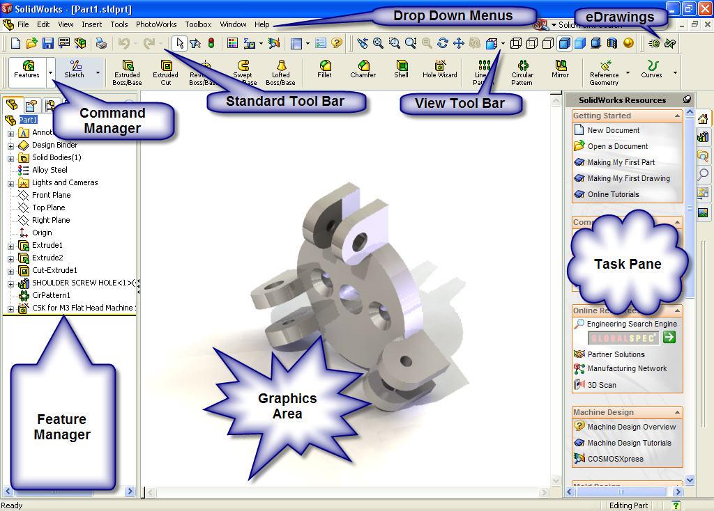
39 2.0 What is SolidWorks? SolidWorks mechanical design automation software is a feature-based, parametric solid modelling design tool which takes advantage of the easy to learn Windows graphical user interface. You can create fully associative 3-D solid models with or without constraints while utilizing automatic or user defined relations to capture design intent. 2.1 Feature-based Just as an assembly is made up of a number of individual piece parts, a SolidWorks model is also made up of individual shapes/forms known as features. The SolidWorks interface allows near intuitive creation of geometric features such as bosses, cuts, holes, ribs, fillets, chamfers, and draft. As the features are created they are applied directly to the work piece. Features can be classified as either sketched or applied. Sketched Features: One that is based upon a 2-D sketch only this type can be used as a base feature. Applied Features: Created directly on the solid model. Fillets and chamfers are examples of this type of feature. To illustrate the concept of feature-based modelling, consider the part shown at the right: This part can be visualized as a collection of several different features some of which add material, like the cylindrical boss, and some which remove material, like the blind hole. If we were to map the individual features to their corresponding listing in the FeatureManager design tree, it would look like this: 15

40 Fig 2.0: Features mapped from their position in the FeatureManager design tree to their position in the model seen in the graphics window 2.2 Parametric The dimensions and relations used to create a feature are captured and stored in the model. This not only enables you to capture your design intent, it also allows you to quickly and easily make changes to the model. Driving Dimensions Relations: These are the dimensions used when creating a feature. They include the dimensions associated with the sketch geometry, as well as those associated with the feature itself. A simple example of this would be a feature like a cylindrical boss. The diameter of the boss is controlled by the diameter of the sketched circle. The height of the boss is controlled by the depth to which that circle was extruded when the feature was made. These include such information as parallelism, tangency, and concentricity. Historically, this type of information has been communicated on drawings via feature control symbols. By capturing this in the sketch, SolidWorks enables the user to fully capture your design intent up front, in the model. 2.3 Solid Modelling A solid model is the most complete type of geometric model used in CAD systems. It contains all the wire frame and surface geometry necessary to fully describe the edges and faces of the model. In addition to the geometric information, it has the information called topology that relates the geometry together. An example of topology would be which faces (surfaces) meet at which edge (curve). This intelligence makes operations such a filleting as easy as selecting an edge and specifying a radius. 2.4 Fully Associative A SolidWorks model is fully associative to the drawings and assemblies that reference it. Changes to the model are automatically reflected in the associated drawings and assemblies. Likewise, you can make changes in the context of the drawing or assembly and know that those changes will be reflected back in the model. 16

41 3.0 Create A Part 17
42 3.0 Create Your First Part Stages in the Process Create a New part document New parts can be created in inch, millimetre or other units. Parts are used to create and hold the solid model. Sketch the profile Sketches are collections of 2D geometry that are used to create solid features. These include lines, circles and rectangles. Applying Sketch relations and dimensions Geometric relationships such as horizontal and vertical are applied to the sketch geometry. Dimension size the geometry while the relations restrict the movement of the entities. Extruding the sketch Extruding uses the 2D sketch to create a 3D solid feature. 3.1 Procedure The process in this lesson includes sketching and extrusions. To begin with, a new part file is created. Tip: Name all your features and sketches. This is an efficient way to design particularly and vital in terms of communicating the information to others. Rename items by slowly clicking two times on a name in the FeatureManager design tree to select it and then entering a new name. Important: Save your work: save and save regularly. An assembly should be saved in the same directory as all its component files. 18


43 3.1.1 Create a New part document 1. New part Opening a New SolidWorks document 19


44 2. Filing a part. Using the Save option from the File menu or selecting the Save button on the Standard toolbar; file the part under the name Candle Holder. The extension, *.sldprt, is added automatically. Click Save. Saving a document 3. Select the Plane we want to Sketch on. In this case it will be the top Plane It is important to choose the correct plane to sketch on this is done by selecting the best profile to sketch of the part. The best profile to sketch is the profile when selected extruded generated the majority or most complexities of the part. The direction we look at to part to get the get the best profile whether it be the plan, elevation or end view will determine sketching on the Top, Front or Right Plane. By giving careful thought to which plane is used to sketch the profile, the proper views are easily generated on the detail drawing. 20
 Relations Added Relations Dimensions Equations Link Values")
45 4. What is Design Intent: Design Intent is our plan as to how our model should behave when changes are made. How Do we Imbed Design intent? We can imbed design intent following the steps below: Choose the Best Profile Choose the Plane Sketch Rough Sketch Automatic (sketch) Relations Added Relations Dimensions Equations Link Values Extrusion Type of extrusion used End Condition Blind Mid Plane 5. Create our sketch by selecting the Top Plane and then the Sketch Icon Rule of Thumb When Sketching Rough Sketch Add Relations Add Dimensions Relations such as parallel, horizontal, vertical and tangent and so on, can be automatically added to the sketch while sketching. Link Values / Equations 21

46 6. We know we are actively in a sketch by the following screen. 7. Select the Line Command on the sketch toolbar and draw a rectangle on the screen. The positioning of the sketch in relation to the origin is important. ( your sketch must be attached to the origin in some form in order to fully define the sketch) Tip: By positioning the origin in the centre of the square - using a construction line the origin is positioned in the centre. This enables you to place the circle in the centre of the cube very easily later on. Also your Front and Right Plane split cube about the centre. 22

47 8. Dimension the Sketch 100mm X 100mm using the dimension icon 9. Conditions of a Sketch. Under Defined There is inadequate definition of the sketch, but the sketch can still be used to create features. This is good because many times in the early stages of the design process, there isn t sufficient information to fully define the sketch. When more information becomes available, the remaining definition can be added at a later time. Under defined sketch geometry is blue (by default). Fully Defined The sketch has complete information. Fully defined geometry is Black (by default). As a general rule, when a model is completed, the sketches within it should be fully defined. Over Defined The sketch has duplicate dimensions or conflicting relations and it should not be used until repaired. Unnecessary dimensions and relations should be deleted. Over defined geometry is red (by default). 9. Select the Features Icon on the Command Manager. 23

48 10. Select the extrude command and extrude the 2d Profile 100mm Design Intent at extrusion stage. Examples of design intent in respect of features Base Extrude Revolve Cut Extrudes Shell Fillets Chamfer Examples of design intent in respect to End Conditions of features Blind Through all Mid-plane Up to Next Up to Surface 24
49 11. Select Top Face of the Cube and create a sketch by selecting the Sketch icon 12. Select a circle command start the center of the circle at the origin. 13. Give the circle a dimension of 50mm. 25
50 14. Select the Cut Extrude command form the Feature Tool Bar. 15. Cut Extrude Blind into the cube 20mm. 26

51 17. Create a Sketch on the Front Face of the Cube. 18. Using the Centre Line command sketch a centre line across the diagonal 19. Using the Polygon Command, sketch a polygon starting on the midpoint of the centre line. 20. Select the top line of the polygon and add the relationship of horizontal in the Property Manager 21. Dimension the top line of the polygon 30mm. 27
52 22. Cut Extrude the Sketch 20mm 23. Add a chamfer to the Polygon. 24. Select the Chamfer icon from the Features Tool Bar 28
53 25. Select all 6 edges of the Polygon. Distance 5mm with an angle of 45 deg. 26. Apply the same chamfer to the edge of the circle. 29
54 27. Add Fillet to all 8 edges as can be seen in Picture. 28. Select Fillet command from the Features Tool Bar. 29. Select all 8 edges as per picture apply 10mm fillet. Preview of fillet will show before accepting, click on the green arrow to accept. 30
55 30. Apply a material to the Candle Holder. In the Feature Manager right click on add material and select brass and say ok. 31. Save the Part File. 31

56 4.0 Create A Drawing 32

57 1. Click on Make a drawing in the Standard Icon Toolbar. 2. Select Drawing A4L 33
 5.")

58 3. Position the Front Elevation on the drawing sheet and Left click. 4. Move Mouse to the Left of the Front Elevation to Create the Side Elevation (left click to position view) 5. Move Mouse Under the Front Elevation to Create the Plan View / Top View (left Click to position View) 6. Move Mouse up too the Left Diagonal of the Front View to Create the isometric view. Hold down the Ctrl key and position the view under the Side Elevation. (Left Click to Position View) 34


59 7. Hold Down the Ctrl Key and Select all Drawing Views. 8. Select the Hidden Lines icon from the views toolbar to show hidden lines in all views. 9. Drawing Views Should Look like below 10. Select the Isometic view and click on the shaded view Icon with edges 35

60 11. Select Annotations Tab on the Command Manager. 12. To Insert Dimensions to the model select Insert Model Items. Make sure these are been applied to the entire model 36

61 13. Smart dimensions can be used to apply any missing dimensions manually. 14. Save and Close your Drawing. 37

62 5.0 Create An Assembly 38


63 1. Open the Candle Holder. 2. Select Make assembly icon form the standard toolbar icons. 3. Select the Candle holde in the open Documents box that shows in the property manager 4. Select the Green tick to place the Candle Holder in an Assembly. 39

64 5. Creat a part named candle at appropriate size (Diameter 50mm) and save to the same location as the candle holder. Open this part. 6. Tile Windows Horizontally 40


65 7. Drag and Drop the Candle into the Assembly leave float in mid air. 41


66 8. Add mates to position the Candle in the Holder. On the Assemblies toolbar select the paper clip icon. 9. Select the Two Cylindrical faces to align the candle to the hole in the holder. Use concentric mate. 42
67 10. Select the bottom face of the candle and the top face of the inside the hole and apply a coincident mate. 11. Now you have created your first assembly save the document. 12. Now Create you own Drawing of the assembly following the part Drawing example. 43

68 6.0 Exercises 44
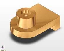
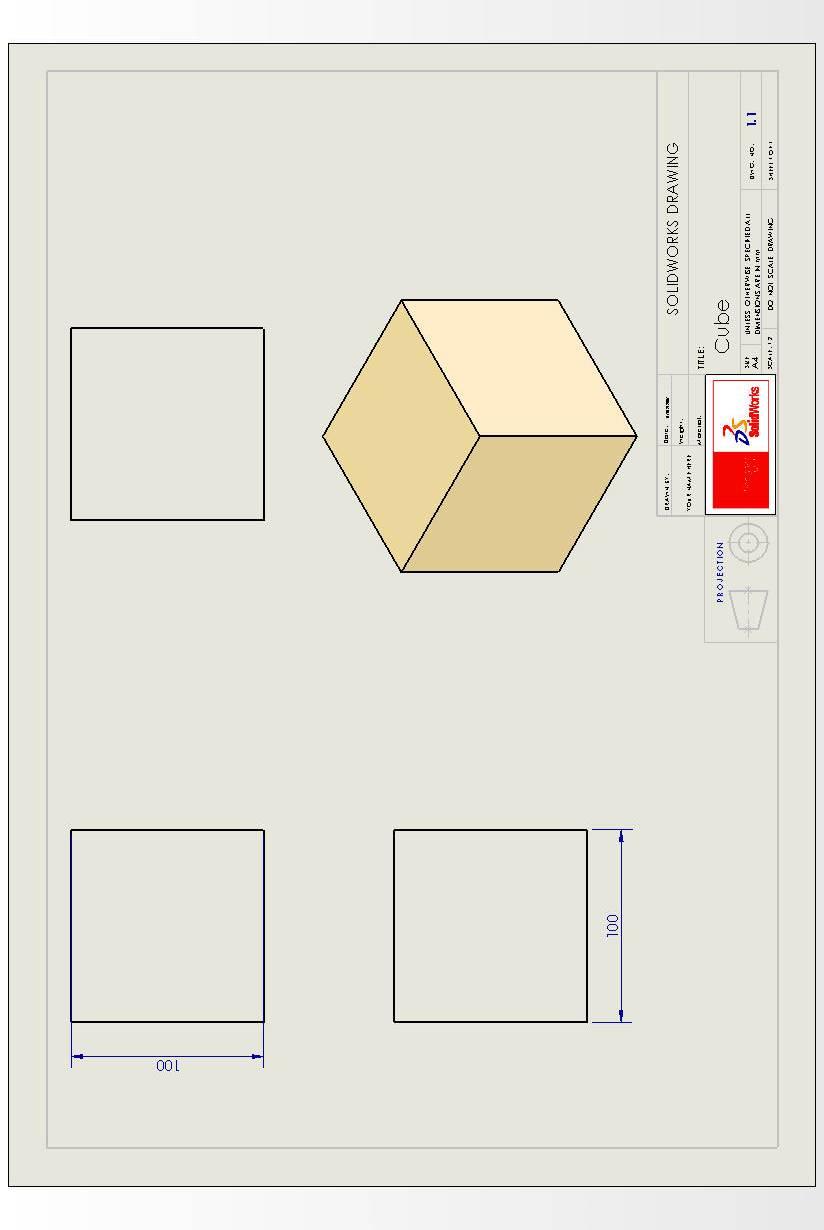
69 Exercise 1: Cube. 1.1 Objectives of this Lesson Model the Cube. New commands: Extrusion 1.2 Lesson Outline Sketch rectangle on the Top Plane. Add equals relationship to all sides. Extrude the Sketch 100mm. Link Values of the dimensions. 1.3 Design Intent Changing one Dimension gives different size cubes 1.4 Productivity Tip Add relations before you add dimensions 1.5 Modelling Tasks Fully define the part using only the given dimensions. 1.6 Create a Drawing 45
70 46
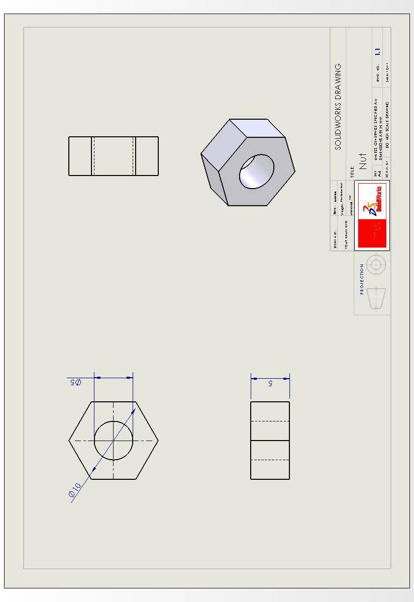
71 Exercise 2: Nut. 2.1 Objectives of this Lesson Model the Nut. New commands: Extrusion. 2.2 Lesson Outline Sketch Polygon on the Front Plane Include the circular hole in the sketch. Extrude the profile. 2.3 Design Intent One feature should be used. 2.4 Productivity Tip You can embed the hole in the initial sketch 2.5 Modelling Tasks Fully define the part using only the given dimensions. 2.6 Create a Drawing 47
72 48
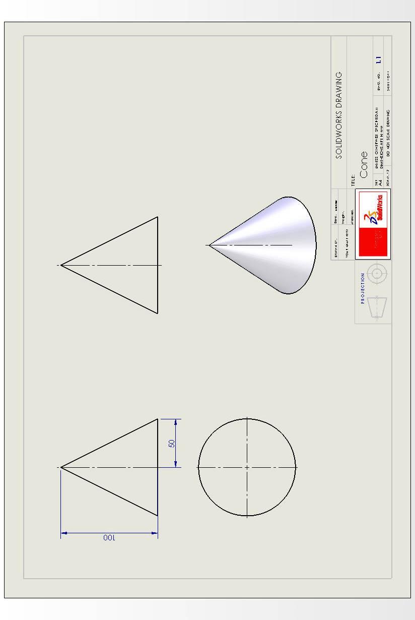
73 Exercise 3: Cone. 3.1 Objectives of this Lesson Model the Cone. New commands: Revolve Feature 3.2 Lesson Outline Sketch a Vertical Centre Line on the Front Plane. Sketch a Triangle using The Dimensions on the Drawing. Revolve the Sketch around the Centre Line Created. 3.3 Design Intent Use Revolve Feature to Create the Part The axis of the Cone should pass through the origin. 3.4 Productivity Tip The Length of the Centre Line does not have to be the same height of the cone it can be larger. 3.5 Modelling Tasks Fully define the part using only the given dimensions. 3.6 Create a Drawing 49
74 50
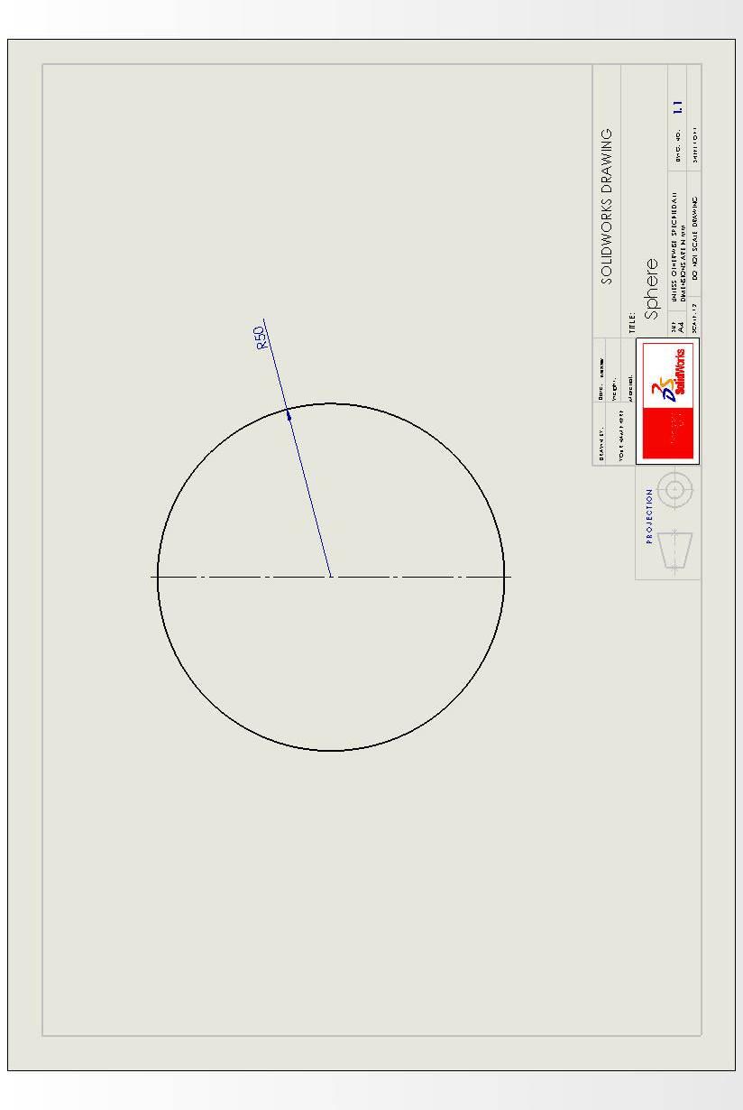
75 Exercise 10: Sphere. 3.1 Objectives of this Lesson Model the Sphere. New commands: Revolve Feature 3.2 Lesson Outline Sketch a Vertical Centre Line on a Plane. Create a Semi-Circle using the Centre Point Arc Command. Revolve the Sketch around the Centre Line Created. 3.3 Design Intent Use Revolve Feature to Create the Part The axis of the Sphere should pass through the origin 3.4 Productivity Tip The Length of the Centre Line can be of any length 3.5 Modelling Tasks Fully define the part using only the given dimensions. 3.6 Create a Drawing 51
76 52
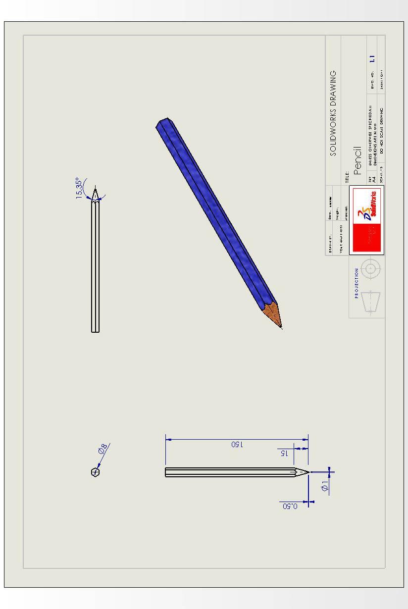
77 Exercise 4: Pencil 4.1 Objectives of this Lesson Model the basic pencil shown here. New commands: Revolved feature, Dome feature. 4.2 Lesson Outline Sketch a polygon profile of the pencil on the front plane with the origin in the centre. Fully define the profile using relations/constraints and the given dimensions. Extrude the Profile the Full length of the Pencil. Use a Revolved Cut to pear the top of the pencil. Create the Sketch of the revolved cut on the top profile. Use the Dome Feature to create the tip of the pencil. Use the Colour palette to give the features different colours. Save your model. 4.3 Design Intent The axis of the pencil should pass through the origin. There should be just three features in your model. 4.4 Productivity Tip The sketch profile for the revolved feature cannot cross the axis/centre line. 4.5 Modelling Tasks Fully define the vase using only the given dimensions. 4.6 Create a Drawing 53
78 54

79 Computer Aided Design Module 2 Lesson Tee Dovetail Halving
80
81 Computer Aided Design Module 2 Lesson Tee Halving
82

83 Computer Aided Design Module 2 Lesson Whistle

84 Lesson Whistle Commands used: Sketch Circle, Line, Rectangle, Centre Arc, Trim, Add Relation, Mirror sketch, Smart dimension, Extruded Boss/Base, Cut Extrude, Revolved Boss/Boss, Fillet, Shell, & Edit Material Approach to Lesson: Create sketch for the body of the whistle Create the sketch on the Front Plane using the Circle and Line sketch commands. Use Trim to remove arc and line. Make this line and the Origin Coincident by using Add Relation Use Smart Dimension to dimension the sketch Whistle body Extrude the sketch using Extruded Boss/Base Select Mid Plane as the end condition and a distance of 18mm. Rename the feature as Whistle Body. First cut to mouth of the whistle Create one half of the sketch on the top surface of the whistle using the Line command. Sketch the a Centreline and Mirror three lines about the centreline to create the other half. Smart Dimension the sketch.


85 Cut Extrude Second cut to mouth of whistle Cut Extrude using this sketch. Select Up to Next as the end condition. Rename the feature as First cut Create sketch on the top surface of the whistle using Centreline and Centre Arc. Make the arc tangential to the right hand edge by using Add Relation Smart Dimension. Cut Extrude Cut Extrude using this sketch (line). Through All is the automatic end condition. Ensure the direction is pointing away from the body of the whistle Rename the feature as Second cut. Apply fillet to top edges Apply a 1mm fillet to the top edges of the whistle. Rename the feature as Top fillet Raised area for ring attachment Create the sketch below on the Front Plane using Line, Add Relation and Smart Dimension. Revolved Boss/Base to raised area Use Revolved Boss/Base to create the area.


86 Rename the feature as Raised area. Shell Shell the whistle with a wall thickness of.5mm. Remove one face. Rename the feature as Shelling of whistle. Opening Create sketch on the top surface of the whistle using a Rectangle Smart Dimension Extrude Cut with this sketch to create the opening. Select Up to Surface as the end condition and select the inside surface. Rename the feature as Opening. Hole Create the sketch on the front plane Extrude Cut with this sketch to create the hole. Select Mid Plane as the end condition and a distance of 10m Rename as Hole. Edit Material Apply a Chrome Stainless Steel finish using Edit Material
87
Toothbrush Holder. A drawing of the sheet metal part will also be created.
 Prerequisite Knowledge Previous knowledge of the following commands is required to complete this lesson; Sketch (Line, Centerline, Circle, Add Relations, Smart Dimension,), Extrude Boss/Base, and Edit
Engineering Technology
 Engineering Technology Introduction to Parametric Modelling Engineering Technology 1 See Saw Exercise Part 1 Base Commands used New Part This lesson includes Sketching, Extruded Boss/Base, Hole Wizard,
SolidWorks Part I - Basic Tools SDC. Includes. Parts, Assemblies and Drawings. Paul Tran CSWE, CSWI
 SolidWorks 2015 Part I - Basic Tools Includes CSWA Preparation Material Parts, Assemblies and Drawings Paul Tran CSWE, CSWI SDC PUBLICATIONS Better Textbooks. Lower Prices. www.sdcpublications.com Powered
Digital Camera Exercise
 Commands Used New Part This lesson includes Sketching, Extruded Boss/Base, Extruded Cut, Fillet, Chamfer and Text. Click File, New on the standard toolbar. Select Part from the New SolidWorks Document
Beginner s Guide to SolidWorks Alejandro Reyes, MSME Certified SolidWorks Professional and Instructor SDC PUBLICATIONS
 Beginner s Guide to SolidWorks 2008 Alejandro Reyes, MSME Certified SolidWorks Professional and Instructor SDC PUBLICATIONS Schroff Development Corporation www.schroff.com www.schroff-europe.com Part Modeling
Engineering Design. with SolidWorks A Step-by-Step Project Based Approach Utilizing 3D Solid Modeling
 INSIDE: MultiMedia CD An audio/visual presentation of the tutorial projects Engineering Design with SolidWorks 2010 A Step-by-Step Project Based Approach Utilizing 3D Solid Modeling Introductory Level
SolidWorks 95 User s Guide
 SolidWorks 95 User s Guide Disclaimer: The following User Guide was extracted from SolidWorks 95 Help files and was not originally distributed in this format. All content 1995, SolidWorks Corporation Contents
AEROPLANE. Create a New Folder in your chosen location called Aeroplane. The four parts that make up the project will be saved here.
 AEROPLANE Prerequisite Knowledge Previous knowledge of the following commands is required to complete this lesson. Sketching (Line, Rectangle, Arc, Add Relations, Dimensioning), Extrude, Assemblies and
Modeling Basic Mechanical Components #1 Tie-Wrap Clip
 Modeling Basic Mechanical Components #1 Tie-Wrap Clip This tutorial is about modeling simple and basic mechanical components with 3D Mechanical CAD programs, specifically one called Alibre Xpress, a freely
SolidWorks 2005 Tutorial. and MultiMedia CD. A Step-by-step Project Based Approach Utilizing 3D Solid Modeling
 INSIDE: MultiMedia CD An audio/visual presentation of the tutorial projects SolidWorks 2005 Tutorial and MultiMedia CD A Step-by-step Project Based Approach Utilizing 3D Solid Modeling David C. Planchard
Introduction to Circular Pattern Flower Pot
 Prerequisite Knowledge Previous knowledge of the sketching commands Line, Circle, Add Relations, Smart Dimension is required to complete this lesson. Previous examples of Revolved Boss/Base, Cut Extrude,
Shaft Hanger - SolidWorks
 ME-430 INTRODUCTION TO COMPUTER AIDED DESIGN Shaft Hanger - SolidWorks BY: DR. HERLI SURJANHATA ASSIGNMENT Submit TWO isometric views of the Shaft Hanger with your report, 1. Shaded view of the trimetric
Introducing SolidWorks
 Introducing SolidWorks SAAST Robotics 2008 SolidWorks Software Visually-based 3-D Mechanical design software Engineers and Designers use it to: Quickly sketch out ideas Experiment with features, dimensions
SolidWorks Training. Introductory course for staff and students from the School of Physics and Astronomy
 SolidWorks Training Introductory course for staff and students from the School of Physics and Astronomy i) Introductory presentation SolidWorks Training ii) The SolidWorks GUI The SolidWorks Graphical
Lesson 6 2D Sketch Panel Tools
 Lesson 6 2D Sketch Panel Tools Inventor s Sketch Tool Bar contains tools for creating the basic geometry to create features and parts. On the surface, the Geometry tools look fairly standard: line, circle,
SolidWorks Design & Technology
 SolidWorks Design & Technology Training Course at PHSG Ex 5. Lego man Working with part files 8mm At first glance the Lego man looks complicated but I hope you will see that if you approach a project one
Evaluation Chapter by CADArtifex
 The premium provider of learning products and solutions www.cadartifex.com EVALUATION CHAPTER 2 Drawing Sketches with SOLIDWORKS In this chapter: Invoking the Part Modeling Environment Invoking the Sketching
Engineering & Computer Graphics Workbook Using SOLIDWORKS
 Engineering & Computer Graphics Workbook Using SOLIDWORKS 2017 Ronald E. Barr Thomas J. Krueger Davor Juricic SDC PUBLICATIONS Better Textbooks. Lower Prices. www.sdcpublications.com Powered by TCPDF (www.tcpdf.org)
Lab 3 Introduction to SolidWorks I Silas Bernardoni 10/9/2008
 1 Introduction This lab is designed to provide you with basic skills when using the 3D modeling program SolidWorks. You will learn how to build parts, assemblies and drawings. You will be given a physical
SolidWorks 103: Barge Design Challenge
 SolidWorks 103: Barge Design Challenge Note: This tutorial was created using SolidWorks 2009. If you are using another version of SolidWorks, you may notice some variation in display states and configuration.
Lesson 10: Loft Features
 10 Goals of This Lesson Your students will be able to create the following part: profiles chisel This lesson plan corresponds to the Loft Features chapter of SolidWorks Getting Started. SolidWorks Student
Introduction to Sheet Metal Features SolidWorks 2009
 SolidWorks 2009 Table of Contents Introduction to Sheet Metal Features Base Flange Method Magazine File.. 3 Envelopment & Development of Surfaces.. 14 Development of Transition Pieces.. 23 Conversion to
Introduction to 3D CAD with SolidWorks. Jianan Li
 Introduction to 3D CAD with SolidWorks Jianan Li Create a New Part The first time you launch SolidWorks, it asks you to set the default units and dimension standard. Make sure you have IPS and ANSI selected,
Below are the desired outcomes and usage competencies based on the completion of Project 4.
 Engineering Design with SolidWorks Project 4 Below are the desired outcomes and usage competencies based on the completion of Project 4. Project Desired Outcomes: An understanding of the customer s requirements
Introduction to Revolve - A Glass
 Introduction to Revolve - A Glass Design & Communication Graphics 1 Object Analysis sheet Design & Communication Graphics 2 Prerequisite Knowledge Previous knowledge of the following commands are required
Engineering & Computer Graphics Workbook Using SolidWorks 2014
 Engineering & Computer Graphics Workbook Using SolidWorks 2014 Ronald E. Barr Thomas J. Krueger Davor Juricic SDC PUBLICATIONS Better Textbooks. Lower Prices. www.sdcpublications.com Powered by TCPDF (www.tcpdf.org)
Getting Started. Chapter. Objectives
 Chapter 1 Getting Started Autodesk Inventor has a context-sensitive user interface that provides you with the tools relevant to the tasks being performed. A comprehensive online help and tutorial system
< Then click on this icon on the vertical tool bar that pops up on the left side.
 Pipe Cavity Tutorial Introduction The CADMAX Solid Master Tutorial is a great way to learn about the benefits of feature-based parametric solid modeling with CADMAX. We have assembled several typical parts
for Solidworks TRAINING GUIDE LESSON-9-CAD
 for Solidworks TRAINING GUIDE LESSON-9-CAD Mastercam for SolidWorks Training Guide Objectives You will create the geometry for SolidWorks-Lesson-9 using SolidWorks 3D CAD software. You will be working
Introduction to Autodesk Inventor for F1 in Schools (Australian Version)
") Introduction to Autodesk Inventor for F1 in Schools (Australian Version) F1 in Schools race car In this course you will be introduced to Autodesk Inventor, which is the centerpiece of Autodesk s Digital
Introduction to Autodesk Inventor for F1 in Schools (Australian Version) F1 in Schools race car In this course you will be introduced to Autodesk Inventor, which is the centerpiece of Autodesk s Digital
Starting a 3D Modeling Part File
 1 How to Create a 3D Model and Corresponding 2D Drawing with Dimensions, GDT (Geometric Dimensioning and Tolerance) Symbols and Title Block in SolidWorks 2013-2014 By Edward Locke This tutorial will introduce
Copyrighted. Material. Copyrighted. Material. Copyrighted. Material. Copyrighted. Material
 ENGINEERING & COMPUTER GRAPHICS WORKBOOK Using SolidWorks 2008 Ronald E. Barr Thomas J. Krueger Theodore A. Aanstoos Davor Juricic SDC PUBLICATIONS Schroff Development Corporation www.schroff.com Better
SDC. SolidWorks Tutorial 2001Plus. A Competency Project Based Approach Utilizing 3D Solid Modeling. David C. Planchard & Marie P.
 2001Plus A Competency Project Based Approach Utilizing 3D Solid Modeling David C. Planchard & Marie P. Planchard SDC PUBLICATIONS www.schroff.com www.schroff-europe.com Project 2 Below are the desired
Creo Parametric Primer
 PTC Creo Parametric - Primer Student and Academic Editions 02 Helpful hints are enclosed in red brackets or round bubbles like this one! Creo Parametric Primer THIS VERSION OF THE CREO PRIMER HAS BEEN
Modeling an Airframe Tutorial
 EAA SOLIDWORKS University p 1/11 Difficulty: Intermediate Time: 1 hour As an Intermediate Tutorial, it is assumed that you have completed the Quick Start Tutorial and know how to sketch in 2D and 3D. If
Copyrighted. Material. Copyrighted. Material. Copyrighted. Material. Copyrighted. Material
 ENGINEERING & COMPUTER GRAPHICS WORKBOOK Using SolidWorks 2005 Ronald E. Barr Thomas J. Krueger Theodore A. Aanstoos Davor Juricic SDC PUBLICATIONS Schroff Development Corporation www.schroff.com www.schroff-europe.com
Introduction to CATIA V5
 Introduction to CATIA V5 Release 17 (A Hands-On Tutorial Approach) Kirstie Plantenberg University of Detroit Mercy SDC PUBLICATIONS Schroff Development Corporation www.schroff.com Better Textbooks. Lower
Working With Drawing Views-I
 Chapter 12 Working With Drawing Views-I Learning Objectives After completing this chapter you will be able to: Generate standard three views. Generate Named Views. Generate Relative Views. Generate Predefined
Advance Dimensioning and Base Feature Options
 Chapter 4 Advance Dimensioning and Base Feature Options Learning Objectives After completing this chapter you will be able to: Dimension the sketch using the autodimension sketch tool. Dimension the sketch
Engineering Design with SolidWorks A Step-by-Step Project Based Approach Utilizing 3D Solid Modeling. David C. Planchard & Marie P.
 Engineering Design with SolidWorks 2003 A Step-by-Step Project Based Approach Utilizing 3D Solid Modeling David C. Planchard & Marie P. Planchard SDC PUBLICATIONS www.schroff.com www.schroff-europe.com
Sash Clamp. Sash Clamp SW 2015 Design & Communication Graphics Page 1.
 Sash Clamp 1 Introduction: The Sash clamp consists of nine parts. In creating the clamp we will be looking at the improvements made by SolidWorks in linear patterns, adding threads and in assembling the
Lesson 4 Holes and Rounds
 Lesson 4 Holes and Rounds 111 Figure 4.1 Breaker OBJECTIVES Sketch arcs in sections Create a straight hole through a part Complete a Sketched hole Understand the Hole Tool Use Info to extract information
1. Open the Feature Modeling demo part file on the EEIC website. Ask student about which constraints needed to Fully Define.
 BLUE boxed notes are intended as aids to the lecturer RED boxed notes are comments that the lecturer could make Control + Click HERE to view enlarged IMAGE and Construction Strategy he following set of
Quick Start for Autodesk Inventor
 Quick Start for Autodesk Inventor Autodesk Inventor Professional is a 3D mechanical design tool with powerful solid modeling capabilities and an intuitive interface. In this lesson, you use a typical workflow
Module 1G: Creating a Circle-Based Cylindrical Sheet-metal Lateral Piece with an Overlaying Lateral Edge Seam And Dove-Tail Seams on the Top Edge
 Inventor (10) Module 1G: 1G- 1 Module 1G: Creating a Circle-Based Cylindrical Sheet-metal Lateral Piece with an Overlaying Lateral Edge Seam And Dove-Tail Seams on the Top Edge In Module 1A, we have explored
Clock Exercise (Inserting Planes)
") Clock Exercise (Inserting Planes) Prerequisite Knowledge To complete this exercise you will need to be familiar with Sketching, Applying relations, Extrude Boss/ Base, Extrude cut, Applying Textures, Renaming
Clock Exercise (Inserting Planes) Prerequisite Knowledge To complete this exercise you will need to be familiar with Sketching, Applying relations, Extrude Boss/ Base, Extrude cut, Applying Textures, Renaming
Conquering the Rubicon
 Autodesk Inventor R10 Fundamentals: Conquering the Rubicon Elise Moss SDC PUBLICATIONS Schroff Development Corporation www.schroff.com www.schroff-europe.com Schroff Development Corporation P.O. Box 1334
Table of Contents. Lesson 1 Getting Started
 NX Lesson 1 Getting Started Pre-reqs/Technical Skills Basic computer use Expectations Read lesson material Implement steps in software while reading through lesson material Complete quiz on Blackboard
Lesson 4 Extrusions OBJECTIVES. Extrusions
 Lesson 4 Extrusions Figure 4.1 Clamp OBJECTIVES Create a feature using an Extruded protrusion Understand Setup and Environment settings Define and set a Material type Create and use Datum features Sketch
Product Modelling in Solid Works
 Product Modelling in Solid Works In the following exercise you will use solid works to construct the computer mouse shown opposite. In this exercise you will use a number of advanced features to achieve
Hydro Hull. Chapter 21. Boat. A. Save as "HYDRO". Step 1. Open your HULL MID PLANE file (Chapter 2).
.") Chapter 21 Boat Hydro Hull A. Save as "HYDRO". Step 1. Open your HULL MID PLANE file (Chapter 2). Step 2. Click File Menu > Save As. Step 3. Key-in HYDRO for the filename and press ENTER. B. Delete Loft1,
Chapter 21 Boat Hydro Hull A. Save as "HYDRO". Step 1. Open your HULL MID PLANE file (Chapter 2). Step 2. Click File Menu > Save As. Step 3. Key-in HYDRO for the filename and press ENTER. B. Delete Loft1,
SOLIDWORKS 2015 and Engineering Graphics
 SOLIDWORKS 2015 and Engineering Graphics An Integrated Approach Randy H. Shih SDC PUBLICATIONS Better Textbooks. Lower Prices. www.sdcpublications.com Powered by TCPDF (www.tcpdf.org) Visit the following
Student + Instructor:
 BLUE boxed notes are intended as aids to the lecturer RED boxed notes are comments that the lecturer could make Show 01 Solid Modeling Intro slides quickly. SolidWorks Layout slides are on EEIC for reference
IT, Sligo. Equations Tutorial
 Equations Tutorial Parametric Modelling: SolidWorks is a parametric modelling system where parameters, such as dimensions and relations, are used to create and control the geometry of the modelled part.
Chapter 2. Drawing Sketches for Solid Models. Learning Objectives
 Chapter 2 Drawing Sketches for Solid Models Learning Objectives After completing this chapter, you will be able to: Start a new template file to draw sketches. Set up the sketching environment. Use various
Part Design Fundamentals
 Part Design Fundamentals 1 Course Presentation Objectives of the course In this course you will learn basic methods to create and modify solids features and parts Targeted audience New CATIA V5 Users 1
Solidworks: Lesson 4 Assembly Basics and Toolbox. UCF Engineering
 Solidworks: Lesson 4 Assembly Basics and Toolbox UCF Engineering Solidworks We have now completed the basic features of part modeling and it is now time to begin constructing more complex models in the
Chair. Bottom Rail. on the Command Manager. on the Weldments toolbar.
 Chapter 2 Chair Bottom Rail A. Weldments Toolbar. Step 1. Click File Menu > New, click Part and OK. Step 2. Right click Sketch on the Command Manager toolbar and select Weldments, Fig. 1. Step 3. Click
FUSION 360: SKETCHING FOR MAKERS
 FUSION 360: SKETCHING FOR MAKERS LaDeana Dockery 2017 MAKEICT Wichita, KS 1 Table of Contents Interface... 1 File Operations... 1 Opening Existing Models... 1 Mouse Navigation... 1 Preferences... 2 Navigation
1. Create a 2D sketch 2. Create geometry in a sketch 3. Use constraints to position geometry 4. Use dimensions to set the size of geometry
 2.1: Sketching Many features that you create in Fusion 360 start with a 2D sketch. In order to create intelligent and predictable designs, a good understanding of how to create sketches and how to apply
AutoCAD Tutorial First Level. 2D Fundamentals. Randy H. Shih SDC. Better Textbooks. Lower Prices.
 AutoCAD 2018 Tutorial First Level 2D Fundamentals Randy H. Shih SDC PUBLICATIONS Better Textbooks. Lower Prices. www.sdcpublications.com Powered by TCPDF (www.tcpdf.org) Visit the following websites to
From the above fig. After sketching the path and profile select the sweep command First select the profile from property manager tree And then select
 Chapter 5 In sweep command there is a) Two sketch profiles b) Two path c) One sketch profile and one path The sweep profile is used to create threads springs circular things and difficult geometry. For
Module 1C: Adding Dovetail Seams to Curved Edges on A Flat Sheet-Metal Piece
 1 Module 1C: Adding Dovetail Seams to Curved Edges on A Flat Sheet-Metal Piece In this Module, we will explore the method of adding dovetail seams to curved edges such as the circumferential edge of a
Creo Parametric 2.0: Introduction to Solid Modeling. Creo Parametric 2.0: Introduction to Solid Modeling
 Creo Parametric 2.0: Introduction to Solid Modeling 1 2 Part 1 Class Files... xiii Chapter 1 Introduction to Creo Parametric... 1-1 1.1 Solid Modeling... 1-4 1.2 Creo Parametric Fundamentals... 1-6 Feature-Based...
Introduction to SolidWorks Introduction to SolidWorks
 Introduction to SolidWorks Introduction to SolidWorks SolidWorks is a powerful 3D modeling program. The models it produces can be used in a number of ways to simulate the behaviour of a real part or assembly
and Engineering Graphics
 SOLIDWORKS 2018 and Engineering Graphics An Integrated Approach Randy H. Shih SDC PUBLICATIONS Better Textbooks. Lower Prices. www.sdcpublications.com Powered by TCPDF (www.tcpdf.org) Visit the following
Siemens NX11 tutorials. The angled part
 Siemens NX11 tutorials The angled part Adaptation to NX 11 from notes from a seminar Drive-to-trial organized by IBM and GDTech. This tutorial will help you design the mechanical presented in the figure
2809 CAD TRAINING: Part 1 Sketching and Making 3D Parts. Contents
 Contents Getting Started... 2 Lesson 1:... 3 Lesson 2:... 13 Lesson 3:... 19 Lesson 4:... 23 Lesson 5:... 25 Final Project:... 28 Getting Started Get Autodesk Inventor Go to http://students.autodesk.com/
Bottom Rail. Chapter 2. Chair. A. Weldments Toolbar. Step 1. Click File Menu > New, click Part and OK. B. 3D Sketch.
 Chapter 2 Chair Bottom Rail A. Weldments Toolbar. Step 1. Click File Menu > New, click Part and OK. Step 2. Right click Sketch on the Command Manager toolbar and select Weldments, Fig. 1. Step 3. Click
Model House Exercise-( Extrude)
") -( Extrude) Prerequisite knowledge Focus of the lesson Commands Used This lesson requires an understanding of using the sketch commands including Inserting a new sketch Adding sketch geometry Understanding
-( Extrude) Prerequisite knowledge Focus of the lesson Commands Used This lesson requires an understanding of using the sketch commands including Inserting a new sketch Adding sketch geometry Understanding
Alibre Design Tutorial: Loft, Extrude, & Revolve Cut Loft-Tube-1
 Alibre Design Tutorial: Loft, Extrude, & Revolve Cut Loft-Tube-1 Part Tutorial Exercise 5: Loft-Tube-1 [Complete] In this Exercise, We will set System Parameters first, then part options. Then, in sketch
How to Build a Game Console. David Hunt, PE
 How to Build a Game Console David Hunt, PE davidhunt@outdrs.net Covering: Drafts Fillets Shells Patterns o Linear o Circular Using made-for-the-purpose sketches to define reference geometry Using reference
Architecture 2012 Fundamentals
 Autodesk Revit Architecture 2012 Fundamentals Supplemental Files SDC PUBLICATIONS Schroff Development Corporation Better Textbooks. Lower Prices. www.sdcpublications.com Tutorial files on enclosed CD Visit
On completion of this exercise you will have:
 Prerequisite Knowledge To complete this exercise you will need; to be familiar with the SolidWorks interface and the key commands. basic file management skills the ability to rotate views and select faces
SolidWize. Online SolidWorks Training. Simple Sweep: Head Scratcher
 SolidWize Online SolidWorks Training Simple Sweep: Head Scratcher Step 1: Creating the Handle: Sketch Using Inches as the unit create a sketch on the Front plane. Start with the sketch shown below: Create
Inventor-Parts-Tutorial By: Dor Ashur
 Inventor-Parts-Tutorial By: Dor Ashur For Assignment: http://www.maelabs.ucsd.edu/mae3/assignments/cad/inventor_parts.pdf Open Autodesk Inventor: Start-> All Programs -> Autodesk -> Autodesk Inventor 2010
SolidWorks Navigation
 SolidWorks Basics SolidWorks Navigation Command Bar Feature Tree Model Window Simple Box Select the Front plane Create a new sketch Create a Center Rectangle from the origin Smart Dimension the length
Drawing and Assembling
 Youth Explore Trades Skills Description In this activity the six sides of a die will be drawn and then assembled together. The intent is to understand how constraints are used to lock individual parts
Creo Revolve Tutorial
 Creo Revolve Tutorial Setup 1. Open Creo Parametric Note: Refer back to the Creo Extrude Tutorial for references and screen shots of the Creo layout 2. Set Working Directory a. From the Model Tree navigate
g. Click once on the left vertical line of the rectangle.
 This drawing will require you to a model of a truck as a Solidworks Part. Please be sure to read the directions carefully before constructing the truck in Solidworks. Before submitting you will be required
Constructing a Wedge Die
 1-(800) 877-2745 www.ashlar-vellum.com Using Graphite TM Copyright 2008 Ashlar Incorporated. All rights reserved. C6CAWD0809. Ashlar-Vellum Graphite This exercise introduces the third dimension. Discover
The project focuses on the design for a Pencil holder, but could be adapted to any simple assembly.
 Introduction - Teacher Notes Fig 1. The project focuses on the design for a Pencil holder, but could be adapted to any simple assembly. Pro/DESKTOP enables pupils (and teachers) to communicate and model
Solidworks Tutorial Pencil
 The following instructions will be used to help you create a Pencil using Solidworks. These instructions are ordered to make the process as simple as possible. Deviating from the order, or not following
SolidWorks. SolidWorks Workbook Advanced Modeling. Version 2009
 SolidWorks SolidWorks Workbook Advanced Modeling Version 2009 SolidWorks Europe 53, Avenue de l Europe Immeuble DSP 13090 AIX-EN-PROVENCE, France Tel: +33 (0)4 13 10 80 20 Fax: +33 (0)4 13 10 80 21 Email:
EXERCISE ONE: BEACH BUGGY.
 EXERCISE ONE: BEACH BUGGY. Prerequisite knowledge Students should have completed Exercises from the file: Introduction to Assemblies Concept Mates Focus of lesson Commands Used This lesson will focus on
Autodesk Inventor. In Engineering Design & Drafting. By Edward Locke
 Autodesk Inventor In Engineering Design & Drafting By Edward Locke Engineering Design Drafting Essentials Working Drawings: Orthographic Projection Views (multi-view, auxiliary view, details and sections)
Understanding Projection Systems
 Understanding Projection Systems A Point: A point has no dimensions, a theoretical location that has neither length, width nor height. A point shows an exact location in space. It is important to understand
Part 8: The Front Cover
 Part 8: The Front Cover 4 Earpiece cuts and housing Lens cut and housing Microphone cut and housing The front cover is similar to the back cover in that it is a shelled protrusion with screw posts extruding
Module 1H: Creating an Ellipse-Based Cylindrical Sheet-metal Lateral Piece
 Inventor (10) Module 1H: 1H- 1 Module 1H: Creating an Ellipse-Based Cylindrical Sheet-metal Lateral Piece In this Module, we will learn how to create an ellipse-based cylindrical sheetmetal lateral piece
AutoCAD 2D. Table of Contents. Lesson 1 Getting Started
 AutoCAD 2D Lesson 1 Getting Started Pre-reqs/Technical Skills Basic computer use Expectations Read lesson material Implement steps in software while reading through lesson material Complete quiz on Blackboard
06/17/02 Page 1 of 12
 Understanding the Graphical User Interface When you start AutoCAD, the AutoCAD window opens. The window is your design work space. It contains elements that you use to create your designs and to receive
Creo Parametric Primer
 Creo Parametric Primer Creo Parametric Primer Education Editions 2 C2-SE-L1-004-1.0 Written by Tim Brotherhood and Adam Haas Conditions of use Acknowledgements Feedback tbrotherhood@ptc.com Product code
Using Siemens NX 11 Software. The connecting rod
 Using Siemens NX 11 Software The connecting rod Based on a Catia tutorial written by Loïc Stefanski. At the end of this manual, you should obtain the following part: 1 Introduction. Start NX 11 and open
Datum Tutorial Part: Cutter
 Datum Tutorial Part: Cutter Objective: Learn to apply Datums in different ways Directions 1. Datum Axis Creation a. First we need to create a center axis for the cutter b. Model Tab > Datum > Select Axis
Module 2: Radial-Line Sheet-Metal 3D Modeling and 2D Pattern Development: Right Cone (Regular, Frustum, and Truncated)
") Inventor (5) Module 2: 2-1 Module 2: Radial-Line Sheet-Metal 3D Modeling and 2D Pattern Development: Right Cone (Regular, Frustum, and Truncated) In this tutorial, we will learn how to build a 3D model
Inventor (5) Module 2: 2-1 Module 2: Radial-Line Sheet-Metal 3D Modeling and 2D Pattern Development: Right Cone (Regular, Frustum, and Truncated) In this tutorial, we will learn how to build a 3D model
SolidWorks 2014 Part I - Basic Tools
 SolidWorks 2014 Part I - Basic Tools Parts, Assemblies and Drawings Paul Tran CSWE, CSWI SDC PUBLICATIONS Better Textbooks. Lower Prices. www.sdcpublications.com Powered by TCPDF (www.tcpdf.org) Visit
Solid Part Four A Bracket Made by Mirroring
 C h a p t e r 5 Solid Part Four A Bracket Made by Mirroring This chapter will cover the following to World Class standards: Sketch of a Solid Problem Draw a Series of Lines Finish the 2D Sketch Extrude
with Creo Parametric 4.0
 Parametric Modeling with Creo Parametric 4.0 An Introduction to Creo Parametric 4.0 NEW Contains a new chapter on 3D Printing Randy H. Shih SDC PUBLICATIONS Better Textbooks. Lower Prices. www.sdcpublications.com