Module 1H: Creating an Ellipse-Based Cylindrical Sheet-metal Lateral Piece
|
|
|
- Gwen Wilkerson
- 6 years ago
- Views:
Transcription
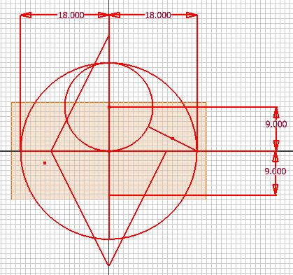
1 Inventor (10) Module 1H: 1H- 1 Module 1H: Creating an Ellipse-Based Cylindrical Sheet-metal Lateral Piece In this Module, we will learn how to create an ellipse-based cylindrical sheetmetal lateral piece with the Contour Flange tool. The Contour Flange tool can create sheet-metal lateral pieces that are developable by the Flat Pattern tool if the Sketch features contain open profile made up of straight line or circular arcs created with the Line or Center Point Circle tools; if the profile is made up of curved line or elliptical arcs created with the Spline or Ellipse tools, the Contour Flange tool can still be used to create the Contour Flange 3D feature, however, the Flat Pattern tool will not be able to generate the Flat Pattern view; instead, if will give the error message shown if Figure 1H-1A. Therefore, a work-around method will be explored to create an ellipse-based cylindrical sheet-metal lateral piece. In traditional geometry construction, a fairly accurate approximation of ellipse can be drawn by combining two sets of circular arcs (we can call this approximation method arcs combination method ), as shown in Figure 1H-1B, since the Contour Flange features are developable by the Flat Pattern tool if the Sketch features contain open profile made up of circular arcs created with the Line or Center Point Circle tools, we will use this work-around method to create an ellipse-based cylindrical sheet-metal lateral piece and its Flat Pattern view. An ellipse can be considered as a circle rotated to a certain angle (Figure 1H-1C); the diameter of the circle that is parallel to the axis of rotation becomes the major axis (also called major axis; in some textbook, half of the major diameter is also called major radius ) of the ellipse; and the foreshortened diameter that is perpendicular to the axis of rotation is the minor diameter (also called minor axis; in some textbook, half of the minor diameter is also called minor radius ).

 elliptical base.")
2 Inventor (10) Module 1H: 1H- 2 Figure 1H-1A: The error message occurring when the Flat Pattern tool tries to develop an elliptical arc-based cylindrical surface. In this Module, we will create cylindrical sheet-metal lateral piece with a 36-inch major diameter (18-in major radius) and 18-inch minor diameter (9-inch minor radius) elliptical base. Figure 1H-1B: The fairly accurate approximation of ellipse drawn by combining two sets of circular arcs (the arcs combination method ).

.ipt template, click OK button (Figure 1H-2A). Figure 1H-2A: Starting a new Sheet Metal (In).")
3 Inventor (10) Module 1H: 1H- 3 Figure 1H-1C: The relationship between a circle and an ellipse. Step 1: Construct the elliptical base profile with the arcs combination method First, we will create a sheet metal file with inch as units. Launch Autodesk Inventor. Create a new sheet metal file (go to the menu File New, or click on the New icon on Standard Tool Bar. The Open window appears. Select the English tab; then select the Sheet Metal (In).ipt template, click OK button (Figure 1H-2A). Figure 1H-2A: Starting a new Sheet Metal (In).ipt file. Figure 1H-2B: Dismissing the default Sketch1 by clicking the Return button.


4 Inventor (10) Module 1H: 1H- 4 Figure 1H-2C: Deleting the default Sketch1. Figure IH-2D: Switching to Isometric View. Figure IH-2E: Turning on the Visibility option.
 to dismiss the Sketch1 feature.")
5 Inventor (10) Module 1H: 1H- 5 Figure IH-2F: Starting a new Sketch. A new sheet metal file opens with two panels docked on the left side of the screen: 2D Sketch (top) and Model (bottom). The Sketch1 opens automatically on the screen; and Sketch1 feature appears on the Model panel. Click the Return key in the Inventor Standard tool bar (Figure 1H-2B) to dismiss the Sketch1 feature. In the Model panel, click the cross on the left of the Origin folder to view the Planes, Axis and Center Point features; click-select the Sketch1 feature and right-click for the shortcut menu and choose the Delete option to delete it (Figure 1H-2C). Next, go to the View Isometric menu to switch to an isometric view (Figure IH-2D). Next, select the XZ Plane, then right-click to open the short cut menu and check the Visibility option (Figure 1H-2E). Next, click-select the XZ Plane and then the Sketch button on the Inventor Standard tool bar to start a new sketch (Figure 1H-2F); Sketch2 feature appears in the Model panel; highlight the Sketch2 name and type Base Profile to rename the feature. Next, click-select the XZ Plane and then the Look At tool button in the Inventor Standard tool bar (Figure IH-2G, left) to switch to an orthographic normal view (Figure 1H-2G, right). Now, we are ready to start the elliptical base profile. Click-select the Project Geometry tool from the 2D Sketch tool panel and then the Center Point from the Model panel to project it onto the Base Profile Sketch; a green dot appears on the center of the Base Profile Sketch; next, select the Line tool from the 2D Sketch tool panel and create two horizontal major radius lines and two vertical minor radius lines, all from the projected Center Point, right-clicking for the shortcut menu and choose the Restart option each time one line is created to create the subsequent line (Figure IH-3A); next, select the General Dimensions tool to apply an 18-inch linear horizontal dimension to both horizontal lines, and a 9-inch linear vertical dimension to the vertical lines (Figure IH-3B); next, select the Center Point Circle tool,

, click once when the green dot snap")
.")
; switching to an orthographic normal view (right).")
6 Inventor (10) Module 1H: 1H- 6 move the cursor closer to the projected Center Point, click once when the green dot snap indicator appears to establish the center point of the circle, and then move the cursor to the left endpoint of the left horizontal line (point A ), click once when the green dot snap indicator appears to establish the radius of the circle (the large construction circle; see Figure IH-3C). Figure IH-2G: Selecting the XZ Plane and clicking the Look At tool button (left); switching to an orthographic normal view (right). Figure IH-3A: Using the Line tool to draw two vertical lines and two horizontal lines.

. Next, use the Trim tool to trim off excessive line segment beyond the construction circle (Figure IH-3F).")
; this small construction circle intersect the inclined line BC at point E.")
7 Inventor (10) Module 1H: 1H- 7 Figure IH-3B: Applying linear dimensions. Next, use the Line tool to create the inclined line segment BC connecting the right endpoint of the right horizontal major radius line and the top endpoint of the top vertical minor radius line (Figure IH-3D); then create the vertical line starting at point B upward beyond the construction circle (the vertical construction line; Figure IH- 3E). Next, use the Trim tool to trim off excessive line segment beyond the construction circle (Figure IH-3F). Next, use the Center Point Circle tool to create the small construction circle (Figure 1H-3G) centered at point B (the top endpoint of the top minor radius line) and with the radius established at point D (the top endpoint of the vertical construction line ); this small construction circle intersect the inclined line BC at point E. Figure IH-3C: Creating the large construction circle with the radius established at point A. Figure IH-3D: Creating the inclined line segment BC.


8 Inventor (10) Module 1H: 1H- 8 Figure IH-3E: Creating the vertical construction line. Figure IH-3F: Trimming off the excessive line segment beyond the construction circle. Figure 1H-3G: Creating the small construction circle. Figure 1H-3H: Trimming off line segment BE.

; this is the perpendicular")
9 Inventor (10) Module 1H: 1H- 9 Figure 1H-3J: The green dot midpoint snap indicator. Figure 1H-3K: Creating the perpendicular bisector line of the inclined line BC. Next, use the Trim tool to trim off line segment BE as shown in Figure 1H-3H. Next, select the Line tool, move the cursor to the midpoint M and click once at the appearance of the green dot midpoint snap indicator (Figure 1H-3J), move away downward and leftward beyond the bottom vertical minor radius line and click once at the appearance of the perpendicular constraint indicator ( symbol inside the red circle, as shown in Figure 1H-3K); this is the perpendicular bisector line of the inclined line BC. Next, use the Line tool to create the vertical line starting at the bottom endpoint of the bottom minor radius line and intersecting the perpendicular bisector line (the extension line; as shown in Figure 1H-3L). Next, use the trim tool to trim off the excessive line segments beyond the point of intersection (Figure 1H-3M and Figure 1H-3N).


10 Inventor (10) Module 1H: 1H- 10 Figure 1H-3L: Creating the vertical line. Figure 1H-3M: Trimming off the excessive line segment. Next, select the Mirror tool; click the Select button in the tool s dialog window and then click-select the perpendicular bisector line; click the Mirror Line button in the tool s dialog window and then click-select the top minor radius line (Figure 1H- 3P); click the OK button in the tool s dialog window to create the mirrored line (Figure 1H-3Q). Use the Mirror tool again; click the Select button in the tool s dialog window and then click-select the mirrored line and the extension line; click the Mirror Line button in the tool s dialog window and then click-select the left major radius line (Figure 1H-3R); click the OK button in the tool s dialog window to create the mirrored lines (Figure 1H-3S). Next, window-select all of the lines drawn so far and click the Construction tool button in the Inventor Standard tool bar to change the line Style to Construction (Figure 1H-3T).


11 Inventor (10) Module 1H: 1H- 11 Figure 1H-3N: Trimming off the excessive line segment. Figure 1H-3P: The Mirror tool s dialog window. Figure 1H-3Q: Creating the mirrored line of the perpendicular bisector line on the left side of the top minor radius line. Figure 1H-3R: Selecting the lines to be mirrored and the Mirror line.

 and to leave a clean set of construction lines")
12 Inventor (10) Module 1H: 1H- 12 Figure 1H-3S: Creating the mirrored lines. Figure 1H-3T: Changing the line Style to Construction. Next, select the Trim tool to trim off excessive line segments (Figure 1H-3U to Figure 1H-3W) and to leave a clean set of construction lines (Figure 1H-3X).


13 Inventor (10) Module 1H: 1H- 13 Figure 1H-3U: Trimming off excessive line segments. Figure 1H-3V: Trimming off excessive line segments. Figure 1H-3W: Trimming off excessive line segments. Figure 1H-3W: Leaving a clean set of construction lines.

.")
14 Inventor (10) Module 1H: 1H- 14 Figure 1H-4A: The large circles. Figure 1H-4B: The small circles. Next, select the Center Point Circle tool to create a circle centered at the point F and with the radius established at the point G, and another circle centered at the point H and with the radius established at the point I (the large circles; as shown in Figure 1H- 4A). Next, use the Center Point Circle tool again to create two circles centered at the points J and K (the small circles; as shown in Figure 1H-4B). Next, select the Tangent tool, click-select one of the large circles and then one of the small circles to enlarge the size of the small circle so that it becomes tangent to both large circles (Figure 1H-4C); repeat the some process for another small circle (Figure 1H-4D).
, so as to leave the approximate elliptical profile, and use")

15 Inventor (10) Module 1H: 1H- 15 Figure 1H-4C: Enlarging the small circle to tangency with the two large circles. Figure 1H-4D: Enlarging the other small circle to tangency with the two large circles. Next, select the Trim tool to trim off the excessive arc segments of large circles and small circles (Figure 1H-4E through Figure 1H-4G), so as to leave the approximate elliptical profile, and use the Zoom Window tool to zoom in the red circled area, as shown in Figure 1H-4H. Next, create a tiny gap in the closed approximate elliptical profile so that the Flat pattern tool can generate the Flat Pattern view after the Contour Flange lateral piece is created; use the Center Point Circle tool to create a small circle centered at the left endpoint of the left major radius line, and use the General Geometry tool to apply an diameter dimension of inch (Figure 1H-4J); use the Zoom Window tool to zoom in several times if needed.


16 Inventor (10) Module 1H: 1H- 16 Figure 1H-4E: Trimming off the excessive arc segments of large circles. Figure 1H-4F: Trimming off the excessive arc segments of large circles. Figure 1H-4G: The excessive arc segments of the small circles to be trimmed off. Figure 1H-4H: The approximate elliptical profile.
ext, click-select the tiny construction circle and press the Delete key on the keyboard to delete it (Figure 1H-4M).")

17 Inventor (10) Module 1H: 1H- 17 Next, select the Trim tool to trim off the tiny segment of arc as shown in Figure 1H-4K; right-click for the shortcut menu and choose the Done option to exit the Trim tool (Figure 1H-4L)ext, click-select the tiny construction circle and press the Delete key on the keyboard to delete it (Figure 1H-4M). Next, click the Return button on the Inventor Standard tool bar; go to the View Isometric menu to switch to an isometric view (Figure 1H-4N). In the Model panel, select the Sketch1 feature, highlight the name and retype Base Profile to rename it. Now, start saving the file. Press Ctrl and s keys simultaneously to save the file as Tut-Elliptical Cylinder.ipt with Part File (*ipt) for Save As Type field, in a convenient directory location, in a new folder to be created and named Tut-Eliptical Cylinder in the Save As window in a convenient directory location (Figure 1H-4P). Save often, at least at the end of each step. Figure 1H-4J: Creating the tiny construction circle for the gap. Figure 1H-4K: Trimming a small gap.


18 Inventor (10) Module 1H: 1H- 18 Figure 1H-4L: Exiting the Trim tool. Figure 1H-4M: Deleting the tiny construction circle. Figure 1H-4N: Switching to an isometric view.

19 Inventor (10) Module 1H: 1H- 19 Figure 1H-4P: Saving the file. Step 2: Create the elliptical-based cylinder with the Contour Flange tool Next, switch to the Sheet Metal Features tool bar and select the Contour Flange tool; click the Profile button in the Contour Flange tool s dialog window and clickselect the elliptical profile from the screen; type 24 in in the Distance text field (Figure 1H-5A); the green outlines of the Contour Flange feature appears on the screen; use the Zoom Window tool to zoom in the leftmost area and click the Offset button in the Contour Flange tool s dialog window until the green outline of the Contour Flange feature indicates that it is projected inwardly (Figure 1H-5B); click the OK button to create the Contour Flange feature and rename it Elliptical Cylinder in the Model panel.

20 Inventor (10) Module 1H: 1H- 20 Figure 1H-5A: Selecting the elliptical profile and typing the Distance value.

21 Inventor (10) Module 1H: 1H- 21 Figure 1H-5B: Zooming in the leftmost area and clicking the Offset button in the Contour Flange tool s dialog window until the green outline of the Contour Flange feature indicates that it is projected inwardly. Step 3: Truncate the elliptical cylinder Next, select the XY Plane feature from the Model panel (Figure 1H-5C) and click the Sketch button from the Inventor Standard tool bar to start a new Sketch feature; rename the Sketch feature as Truncation Profile in the Model panel; click the Look At button in the Inventor Standard tool bar and then the to switch the Truncation Profile to an orthographic normal view. Next, select the Project Geometry button and click the top horizontal edge of the cylindrical piece (Figure 1H-5D); select the projected line and click the Construction tool and change its line Style. Next, select the Center Point Circle tool to create a circle centered at the midpoint of the projected top horizontal edge line; and use the General Dimension tool to apply a 18-inch diameter dimension to the circle. Click the Return button to finish the sketch.


22 Inventor (10) Module 1H: 1H- 22 Figure 1H-5C: Select the XY Plane feature from the Model panel to start a new Sketch. Figure 1H-5D: Switching to an orthographic normal view with the Look At tool and projecting the top horizontal edge with Project Geometry tool. Figure 1H-5E: Changing the line Style to Construction. Figure 1H-5F: Starting to create a circle with the help of the midpoint snap indicator. Next, switch to the Part Features tool panel by clicking the downward-pointing triangle to open up a pull-down list and to select the option (Figure 1H-5H); select the Extrude tool, in the tool s dialog window, select the Cut option for Type and Midplane


; click-select the frontal outer surface of the lateral piece")
23 Inventor (10) Module 1H: 1H- 23 option for Direction (red circled); click the Profile button and click-select the circular profile; select the All option from the Extents pull-down menu; click the OK button to create the Extrude feature (Figure 1H-5J) and rename it as Truncation in the Model panel. Figure 1H-5G: Creating and dimensioning the circle. Figure 1H-5H: Switch to the Part Features tool panel. Figure 1H-5J: Creating the Extrude Cut feature. Next, switch to the Sheet Metal Features (Figure 1H-5K); click-select the frontal outer surface of the lateral piece (Figure 1H-5L) and click the Flat Pattern tool button to create the Flat Pattern view (Figure 1H-6A). If desirable, apple a colorful material

.")


24 Inventor (10) Module 1H: 1H- 24 rendering by selecting a material type from the pull-down menu on the Inventor Standard tool bar (Figure 1H-6B); the Flat Pattern view automatically updates (Figure 1H-6C). Figure 1H-5K: Switching to the Sheet Metal Features. Figure 1H-5L: Selecting the frontal outer surface of the truncated elliptical cylinder for Flat Pattern view generation. Figure 1H-6A: The Flat Pattern view. Figure 1H-6B: Applying an Aluminum (Polished) material rendering.


25 Inventor (10) Module 1H: 1H- 25 Figure 1H-6C (left): The Flat Pattern view automatically updating to the assigned material rendering. Figure 1H-6D (right): The Model panel feature list. Congratulations! In this Module, you have learned how to create a truncated elliptical cylinder sheet-metal part and its Flat Pattern view.
Module 1G: Creating a Circle-Based Cylindrical Sheet-metal Lateral Piece with an Overlaying Lateral Edge Seam And Dove-Tail Seams on the Top Edge
 Inventor (10) Module 1G: 1G- 1 Module 1G: Creating a Circle-Based Cylindrical Sheet-metal Lateral Piece with an Overlaying Lateral Edge Seam And Dove-Tail Seams on the Top Edge In Module 1A, we have explored
Module 1E: Parallel-Line Flat Pattern Development of Sheet- Metal Folded Model Wrapping the 3D Space of An Oblique Circular Cylinder
 Inventor (10) Module 1E: 1E- 1 Module 1E: Parallel-Line Flat Pattern Development of Sheet- Metal Folded Model Wrapping the 3D Space of An Oblique Circular Cylinder In this Module, we will explore the topic
Module 1C: Adding Dovetail Seams to Curved Edges on A Flat Sheet-Metal Piece
 1 Module 1C: Adding Dovetail Seams to Curved Edges on A Flat Sheet-Metal Piece In this Module, we will explore the method of adding dovetail seams to curved edges such as the circumferential edge of a
Module 2: Radial-Line Sheet-Metal 3D Modeling and 2D Pattern Development: Right Cone (Regular, Frustum, and Truncated)
") Inventor (5) Module 2: 2-1 Module 2: Radial-Line Sheet-Metal 3D Modeling and 2D Pattern Development: Right Cone (Regular, Frustum, and Truncated) In this tutorial, we will learn how to build a 3D model
Inventor (5) Module 2: 2-1 Module 2: Radial-Line Sheet-Metal 3D Modeling and 2D Pattern Development: Right Cone (Regular, Frustum, and Truncated) In this tutorial, we will learn how to build a 3D model
Autodesk Inventor. In Engineering Design & Drafting. By Edward Locke
 Autodesk Inventor In Engineering Design & Drafting By Edward Locke Engineering Design Drafting Essentials Working Drawings: Orthographic Projection Views (multi-view, auxiliary view, details and sections)
Lesson 6 2D Sketch Panel Tools
 Lesson 6 2D Sketch Panel Tools Inventor s Sketch Tool Bar contains tools for creating the basic geometry to create features and parts. On the surface, the Geometry tools look fairly standard: line, circle,
Quick Start for Autodesk Inventor
 Quick Start for Autodesk Inventor Autodesk Inventor Professional is a 3D mechanical design tool with powerful solid modeling capabilities and an intuitive interface. In this lesson, you use a typical workflow
1. Create a 2D sketch 2. Create geometry in a sketch 3. Use constraints to position geometry 4. Use dimensions to set the size of geometry
 2.1: Sketching Many features that you create in Fusion 360 start with a 2D sketch. In order to create intelligent and predictable designs, a good understanding of how to create sketches and how to apply
Introduction to CATIA V5
 Introduction to CATIA V5 Release 17 (A Hands-On Tutorial Approach) Kirstie Plantenberg University of Detroit Mercy SDC PUBLICATIONS Schroff Development Corporation www.schroff.com Better Textbooks. Lower
Autodesk Inventor Module 17 Angles
 Inventor Self-paced ecourse Autodesk Inventor Module 17 Angles Learning Outcomes When you have completed this module, you will be able to: 1 Describe drawing inclined lines, aligned and angular dimensions,
Introduction to Autodesk Inventor for F1 in Schools (Australian Version)
") Introduction to Autodesk Inventor for F1 in Schools (Australian Version) F1 in Schools race car In this course you will be introduced to Autodesk Inventor, which is the centerpiece of Autodesk s Digital
Introduction to Autodesk Inventor for F1 in Schools (Australian Version) F1 in Schools race car In this course you will be introduced to Autodesk Inventor, which is the centerpiece of Autodesk s Digital
Inventor-Parts-Tutorial By: Dor Ashur
 Inventor-Parts-Tutorial By: Dor Ashur For Assignment: http://www.maelabs.ucsd.edu/mae3/assignments/cad/inventor_parts.pdf Open Autodesk Inventor: Start-> All Programs -> Autodesk -> Autodesk Inventor 2010
MODELING AND DESIGN C H A P T E R F O U R
 MODELING AND DESIGN C H A P T E R F O U R OBJECTIVES 1. Identify and specify basic geometric elements and primitive shapes. 2. Select a 2D profile that best describes the shape of an object. 3. Identify
11/12/2015 CHAPTER 7. Axonometric Drawings (cont.) Axonometric Drawings (cont.) Isometric Projections (cont.) 1) Axonometric Drawings
 Axonometric Drawings (cont.) Isometric Projections (cont.) 1) Axonometric Drawings") CHAPTER 7 1) Axonometric Drawings 1) Introduction Isometric & Oblique Projection Axonometric projection is a parallel projection technique used to create a pictorial drawing of an object by rotating the
CHAPTER 7 1) Axonometric Drawings 1) Introduction Isometric & Oblique Projection Axonometric projection is a parallel projection technique used to create a pictorial drawing of an object by rotating the
Drawing and Assembling
 Youth Explore Trades Skills Description In this activity the six sides of a die will be drawn and then assembled together. The intent is to understand how constraints are used to lock individual parts
Starting a 3D Modeling Part File
 1 How to Create a 3D Model and Corresponding 2D Drawing with Dimensions, GDT (Geometric Dimensioning and Tolerance) Symbols and Title Block in SolidWorks 2013-2014 By Edward Locke This tutorial will introduce
Chapter 7 Isometric Drawings
 Chapter 7 Isometric Drawings In this assignment, we are going to look at creating isometric drawings with AutoCAD. These drawing appear to be three dimensional but they are not. An AutoCAD isometric drawing
Introduction to Autodesk Inventor User Interface Student Manual MODEL WINDOW
 Emmett Wemp EDTECH 503 Introduction to Autodesk Inventor User Interface Fill in the blanks of the different tools available in the user interface of Autodesk Inventor as your instructor discusses them.
Inventor Activity 5: Lofted Vase
 Inventor Activity 5: Lofted Vase In this tutorial, you will use a few new commands to create a free form Lofted object. Sometimes you want to create an object that is not made up of square, flat, or perfectly
Shaft Hanger - SolidWorks
 ME-430 INTRODUCTION TO COMPUTER AIDED DESIGN Shaft Hanger - SolidWorks BY: DR. HERLI SURJANHATA ASSIGNMENT Submit TWO isometric views of the Shaft Hanger with your report, 1. Shaded view of the trimetric
Chapter 2. Drawing Sketches for Solid Models. Learning Objectives
 Chapter 2 Drawing Sketches for Solid Models Learning Objectives After completing this chapter, you will be able to: Start a new template file to draw sketches. Set up the sketching environment. Use various
SolidWorks Part I - Basic Tools SDC. Includes. Parts, Assemblies and Drawings. Paul Tran CSWE, CSWI
 SolidWorks 2015 Part I - Basic Tools Includes CSWA Preparation Material Parts, Assemblies and Drawings Paul Tran CSWE, CSWI SDC PUBLICATIONS Better Textbooks. Lower Prices. www.sdcpublications.com Powered
AutoCAD Tutorial First Level. 2D Fundamentals. Randy H. Shih SDC. Better Textbooks. Lower Prices.
 AutoCAD 2018 Tutorial First Level 2D Fundamentals Randy H. Shih SDC PUBLICATIONS Better Textbooks. Lower Prices. www.sdcpublications.com Powered by TCPDF (www.tcpdf.org) Visit the following websites to
Toothbrush Holder. A drawing of the sheet metal part will also be created.
 Prerequisite Knowledge Previous knowledge of the following commands is required to complete this lesson; Sketch (Line, Centerline, Circle, Add Relations, Smart Dimension,), Extrude Boss/Base, and Edit
Solid Part Four A Bracket Made by Mirroring
 C h a p t e r 5 Solid Part Four A Bracket Made by Mirroring This chapter will cover the following to World Class standards: Sketch of a Solid Problem Draw a Series of Lines Finish the 2D Sketch Extrude
Introduction to Sheet Metal Features SolidWorks 2009
 SolidWorks 2009 Table of Contents Introduction to Sheet Metal Features Base Flange Method Magazine File.. 3 Envelopment & Development of Surfaces.. 14 Development of Transition Pieces.. 23 Conversion to
Conquering the Rubicon
 Autodesk Inventor R10 Fundamentals: Conquering the Rubicon Elise Moss SDC PUBLICATIONS Schroff Development Corporation www.schroff.com www.schroff-europe.com Schroff Development Corporation P.O. Box 1334
AEROPLANE. Create a New Folder in your chosen location called Aeroplane. The four parts that make up the project will be saved here.
 AEROPLANE Prerequisite Knowledge Previous knowledge of the following commands is required to complete this lesson. Sketching (Line, Rectangle, Arc, Add Relations, Dimensioning), Extrude, Assemblies and
ME Week 2 Project 2 Flange Manifold Part
 1 Project 2 - Flange Manifold Part 1.1 Instructions This project focuses on additional sketching methods and sketching commands. Revolve and Work features are also introduced. The part being modeled is
Table of Contents. Lesson 1 Getting Started
 NX Lesson 1 Getting Started Pre-reqs/Technical Skills Basic computer use Expectations Read lesson material Implement steps in software while reading through lesson material Complete quiz on Blackboard
Getting Started. Right click on Lateral Workplane. Left Click on New Sketch
 Getting Started 1. Open up PTC Pro/Desktop by either double clicking the icon or through the Start button and in Programs. 2. Once Pro/Desktop is open select File > New > Design 3. Close the Pallet window
Modeling Basic Mechanical Components #1 Tie-Wrap Clip
 Modeling Basic Mechanical Components #1 Tie-Wrap Clip This tutorial is about modeling simple and basic mechanical components with 3D Mechanical CAD programs, specifically one called Alibre Xpress, a freely
Evaluation Chapter by CADArtifex
 The premium provider of learning products and solutions www.cadartifex.com EVALUATION CHAPTER 2 Drawing Sketches with SOLIDWORKS In this chapter: Invoking the Part Modeling Environment Invoking the Sketching
When you complete this assignment you will:
 Objjectiives When you complete this assignment you will: 1. Set-up menus and drawing for designing modeling problems. 2. become familiar with the Sketch menu tools and commands. 3. Produce a three-dimensional
FUSION 360: SKETCHING FOR MAKERS
 FUSION 360: SKETCHING FOR MAKERS LaDeana Dockery 2017 MAKEICT Wichita, KS 1 Table of Contents Interface... 1 File Operations... 1 Opening Existing Models... 1 Mouse Navigation... 1 Preferences... 2 Navigation
< Then click on this icon on the vertical tool bar that pops up on the left side.
 Pipe Cavity Tutorial Introduction The CADMAX Solid Master Tutorial is a great way to learn about the benefits of feature-based parametric solid modeling with CADMAX. We have assembled several typical parts
AutoCAD 2D. Table of Contents. Lesson 1 Getting Started
 AutoCAD 2D Lesson 1 Getting Started Pre-reqs/Technical Skills Basic computer use Expectations Read lesson material Implement steps in software while reading through lesson material Complete quiz on Blackboard
Using Siemens NX 11 Software. The connecting rod
 Using Siemens NX 11 Software The connecting rod Based on a Catia tutorial written by Loïc Stefanski. At the end of this manual, you should obtain the following part: 1 Introduction. Start NX 11 and open
Engineering & Computer Graphics Workbook Using SOLIDWORKS
 Engineering & Computer Graphics Workbook Using SOLIDWORKS 2017 Ronald E. Barr Thomas J. Krueger Davor Juricic SDC PUBLICATIONS Better Textbooks. Lower Prices. www.sdcpublications.com Powered by TCPDF (www.tcpdf.org)
SolidWize. Online SolidWorks Training. Simple Sweep: Head Scratcher
 SolidWize Online SolidWorks Training Simple Sweep: Head Scratcher Step 1: Creating the Handle: Sketch Using Inches as the unit create a sketch on the Front plane. Start with the sketch shown below: Create
Alibre Design Tutorial: Loft, Extrude, & Revolve Cut Loft-Tube-1
 Alibre Design Tutorial: Loft, Extrude, & Revolve Cut Loft-Tube-1 Part Tutorial Exercise 5: Loft-Tube-1 [Complete] In this Exercise, We will set System Parameters first, then part options. Then, in sketch
Engineering & Computer Graphics Workbook Using SolidWorks 2014
 Engineering & Computer Graphics Workbook Using SolidWorks 2014 Ronald E. Barr Thomas J. Krueger Davor Juricic SDC PUBLICATIONS Better Textbooks. Lower Prices. www.sdcpublications.com Powered by TCPDF (www.tcpdf.org)
Isometric Drawings. Figure A 1
 A Isometric Drawings ISOMETRIC BASICS Isometric drawings are a means of drawing an object in picture form for better clarifying the object s appearance. These types of drawings resemble a picture of an
Creo Revolve Tutorial
 Creo Revolve Tutorial Setup 1. Open Creo Parametric Note: Refer back to the Creo Extrude Tutorial for references and screen shots of the Creo layout 2. Set Working Directory a. From the Model Tree navigate
Chapter 1. Creating, Profiling, Constraining, and Dimensioning the Basic Sketch. Learning Objectives. Commands Covered
 Chapter 1 Creating, Profiling, Constraining, and Dimensioning the Basic Sketch Learning Objectives After completing this chapter, you will be able to: Draw the basic outline (sketch) of designer model.
DEPARTMENT OF MECHANICAL ENGINEERING, IIT DELHI
 MEL 110 LABORATORY 1 (to be done in CAGI Lab. Room: III 331) DURATION: 3 Hrs 50 Min. Note: Missing dimensions may be suitably assumed. Exercise 1: Visualize orthographic and isometric views of 3D models/objects:
Architecture 2012 Fundamentals
 Autodesk Revit Architecture 2012 Fundamentals Supplemental Files SDC PUBLICATIONS Schroff Development Corporation Better Textbooks. Lower Prices. www.sdcpublications.com Tutorial files on enclosed CD Visit
An Introduction to Dimensioning Dimension Elements-
 An Introduction to Dimensioning A precise drawing plotted to scale often does not convey enough information for builders to construct your design. Usually you add annotation showing object measurements
The Revolve Feature and Assembly Modeling
 The Revolve Feature and Assembly Modeling PTC Clock Page 52 PTC Contents Introduction... 54 The Revolve Feature... 55 Creating a revolved feature...57 Creating face details... 58 Using Text... 61 Assembling
ENGINEERING GRAPHICS 1E9
 Lecture 3 Monday, 15 December 2014 1 ENGINEERING GRAPHICS 1E9 Lecture 3: Isometric Projections Lecture 3 Monday, 15 December 2014 2 What is ISOMETRIC? It is a method of producing pictorial view of an object
SDC. SolidWorks Tutorial 2001Plus. A Competency Project Based Approach Utilizing 3D Solid Modeling. David C. Planchard & Marie P.
 2001Plus A Competency Project Based Approach Utilizing 3D Solid Modeling David C. Planchard & Marie P. Planchard SDC PUBLICATIONS www.schroff.com www.schroff-europe.com Project 2 Below are the desired
Alternatively, the solid section can be made with open line sketch and adding thickness by Thicken Sketch.
 Sketcher All feature creation begins with two-dimensional drawing in the sketcher and then adding the third dimension in some way. The sketcher has many menus to help create various types of sketches.
Using Siemens NX 11 Software. Sheet Metal Design - Casing
 Using Siemens NX 11 Software Sheet Metal Design - Casing Based on a YouTube NX tutorial 1. 1 https://www.youtube.com/watch?v=-siyi1vz87k A&M CAD in mechanical engineering 1 1 Introduction. Start NX 11
Isometric Circles and Arcs
 AutoCAD and Its Applications BASICS Supplemental Material Chapter 4 Isometric Circles and Arcs On an isometric drawing, circles appear as ellipses and arcs as elliptical arcs. You must properly align isometric
SolidWorks 2005 Tutorial. and MultiMedia CD. A Step-by-step Project Based Approach Utilizing 3D Solid Modeling
 INSIDE: MultiMedia CD An audio/visual presentation of the tutorial projects SolidWorks 2005 Tutorial and MultiMedia CD A Step-by-step Project Based Approach Utilizing 3D Solid Modeling David C. Planchard
1.6.7 Add Arc Length Dimension Modify Dimension Value Check the Sketch Curve Connectivity
 Contents 2D Sketch... 1 1.1 2D Sketch Introduction... 1 1.1.1 2D Sketch... 1 1.1.2 Basic Setting of 2D Sketch... 2 1.1.3 Exit 2D Sketch... 4 1.2 Draw Common Geometry... 5 2.2.1 Points... 5 2.2.2 Lines
Autodesk Inventor 2016 Creating Sketches
 Autodesk Inventor 2016 Creating Sketches 2D Sketch Practice 1 1. Launch Autodesk Inventor 2016 2. Create a new Part file (.ipt) 3. Save File As a. Click on the save icon. b. Save you file onto your flash
Bottom Rail. Chapter 2. Chair. A. Weldments Toolbar. Step 1. Click File Menu > New, click Part and OK. B. 3D Sketch.
 Chapter 2 Chair Bottom Rail A. Weldments Toolbar. Step 1. Click File Menu > New, click Part and OK. Step 2. Right click Sketch on the Command Manager toolbar and select Weldments, Fig. 1. Step 3. Click
JUNIOR CERTIFICATE 2009 MARKING SCHEME TECHNICAL GRAPHICS HIGHER LEVEL
 . JUNIOR CERTIFICATE 2009 MARKING SCHEME TECHNICAL GRAPHICS HIGHER LEVEL Sections A and B Section A any ten questions from this section Q1 12 Four diagrams, 3 marks for each correct label. Q2 12 2 marks
2809 CAD TRAINING: Part 1 Sketching and Making 3D Parts. Contents
 Contents Getting Started... 2 Lesson 1:... 3 Lesson 2:... 13 Lesson 3:... 19 Lesson 4:... 23 Lesson 5:... 25 Final Project:... 28 Getting Started Get Autodesk Inventor Go to http://students.autodesk.com/
Activity Sketch Plane Cube
 Activity 1.5.4 Sketch Plane Cube Introduction Have you ever tried to explain to someone what you knew, and that person wanted you to tell him or her more? Here is your chance to do just that. You have
AutoCAD 2018 Fundamentals
 Autodesk AutoCAD 2018 Fundamentals Elise Moss SDC PUBLICATIONS Better Textbooks. Lower Prices. www.sdcpublications.com Powered by TCPDF (www.tcpdf.org) Visit the following websites to learn more about
TOY TRUCK. Figure 1. Orthographic projections of project.
 TOY TRUCK Prepared by: Harry Hawkins The following project is of a small, wooden toy truck. This exercise will provide you with the procedure for constructing the various parts of the design then assembling
AutoCAD LT 2012 Tutorial. Randy H. Shih Oregon Institute of Technology SDC PUBLICATIONS. Schroff Development Corporation
 AutoCAD LT 2012 Tutorial Randy H. Shih Oregon Institute of Technology SDC PUBLICATIONS www.sdcpublications.com Schroff Development Corporation AutoCAD LT 2012 Tutorial 1-1 Lesson 1 Geometric Construction
Activity 1 Modeling a Plastic Part
 Activity 1 Modeling a Plastic Part In this activity, you will model a plastic part. When completed, your plastic part should look like the following two illustrations. While building this model, take time
Understanding Projection Systems
 Understanding Projection Systems A Point: A point has no dimensions, a theoretical location that has neither length, width nor height. A point shows an exact location in space. It is important to understand
Activity 5.2 Making Sketches in CAD
 Activity 5.2 Making Sketches in CAD Introduction It would be great if computer systems were advanced enough to take a mental image of an object, such as the thought of a sports car, and instantly generate
SolidWorks Design & Technology
 SolidWorks Design & Technology Training Course at PHSG Ex 5. Lego man Working with part files 8mm At first glance the Lego man looks complicated but I hope you will see that if you approach a project one
Isometric Drawing Chapter 26
 Isometric Drawing Chapter 26 Sacramento City College EDT 310 EDT 310 - Chapter 26 - Isometric Drawing 1 Drawing Types Pictorial Drawing types: Perspective Orthographic Isometric Oblique Pictorial - like
Create A Mug. Skills Learned. Settings Sketching 3-D Features. Revolve Offset Plane Sweep Fillet Decal* Offset Arc
 Create A Mug Skills Learned Settings Sketching 3-D Features Slice Line Tool Offset Arc Revolve Offset Plane Sweep Fillet Decal* Tutorial: Creating A Custom Mug There are somethings in this world that have
Engineering Technology
 Engineering Technology Introduction to Parametric Modelling Engineering Technology 1 See Saw Exercise Part 1 Base Commands used New Part This lesson includes Sketching, Extruded Boss/Base, Hole Wizard,
Wireless Mouse Surfaces
 Wireless Mouse Surfaces Design & Communication Graphics Table of Contents Table of Contents... 1 Introduction 2 Mouse Body. 3 Edge Cut.12 Centre Cut....14 Wheel Opening.. 15 Wheel Location.. 16 Laser..
SolidWorks 95 User s Guide
 SolidWorks 95 User s Guide Disclaimer: The following User Guide was extracted from SolidWorks 95 Help files and was not originally distributed in this format. All content 1995, SolidWorks Corporation Contents
Chair. Bottom Rail. on the Command Manager. on the Weldments toolbar.
 Chapter 2 Chair Bottom Rail A. Weldments Toolbar. Step 1. Click File Menu > New, click Part and OK. Step 2. Right click Sketch on the Command Manager toolbar and select Weldments, Fig. 1. Step 3. Click
Hydro Hull. Chapter 21. Boat. A. Save as "HYDRO". Step 1. Open your HULL MID PLANE file (Chapter 2).
.") Chapter 21 Boat Hydro Hull A. Save as "HYDRO". Step 1. Open your HULL MID PLANE file (Chapter 2). Step 2. Click File Menu > Save As. Step 3. Key-in HYDRO for the filename and press ENTER. B. Delete Loft1,
Chapter 21 Boat Hydro Hull A. Save as "HYDRO". Step 1. Open your HULL MID PLANE file (Chapter 2). Step 2. Click File Menu > Save As. Step 3. Key-in HYDRO for the filename and press ENTER. B. Delete Loft1,
Siemens NX11 tutorials. The angled part
 Siemens NX11 tutorials The angled part Adaptation to NX 11 from notes from a seminar Drive-to-trial organized by IBM and GDTech. This tutorial will help you design the mechanical presented in the figure
Autodesk AutoCAD 2013 Fundamentals
 Autodesk AutoCAD 2013 Fundamentals Elise Moss SDC P U B L I C AT I O N S Schroff Development Corporation Better Textbooks. Lower Prices. www.sdcpublications.com Visit the following websites to learn more
AutoCAD LT 2009 Tutorial
 AutoCAD LT 2009 Tutorial Randy H. Shih Oregon Institute of Technology SDC PUBLICATIONS Schroff Development Corporation www.schroff.com Better Textbooks. Lower Prices. AutoCAD LT 2009 Tutorial 1-1 Lesson
Tutorial Building the Nave Arcade
 Tutorial: Digital Gothic AH C117B (Winter 2017) Tutorial Building the Nave Arcade Overview: Step 1: Determining and Drawing The Arch (Quinto Arch) Step 2: Extrude Molding Profile Step 3: Adding Walls Step
1. Creating geometry based on sketches 2. Using sketch lines as reference 3. Using sketches to drive changes in geometry
 4.1: Modeling 3D Modeling is a key process of getting your ideas from a concept to a read- for- manufacture state, making it core foundation of the product development process. In Fusion 360, there are
Introduction to 3D CAD with SolidWorks. Jianan Li
 Introduction to 3D CAD with SolidWorks Jianan Li Create a New Part The first time you launch SolidWorks, it asks you to set the default units and dimension standard. Make sure you have IPS and ANSI selected,
Datum Tutorial Part: Cutter
 Datum Tutorial Part: Cutter Objective: Learn to apply Datums in different ways Directions 1. Datum Axis Creation a. First we need to create a center axis for the cutter b. Model Tab > Datum > Select Axis
Getting started with. Getting started with VELOCITY SERIES.
 Getting started with Getting started with SOLID EDGE EDGE ST4 ST4 VELOCITY SERIES www.siemens.com/velocity 1 Getting started with Solid Edge Publication Number MU29000-ENG-1040 Proprietary and Restricted
Made Easy. Jason Pancoast Engineering Manager
 3D Sketching Made Easy Jason Pancoast Engineering Manager Today I have taught you to sketch in 3D. It s as easy as counting ONE, TWO, FIVE...er...THREE! When your sketch only lives in Y and in X, Adding
Beginner s Guide to SolidWorks Alejandro Reyes, MSME Certified SolidWorks Professional and Instructor SDC PUBLICATIONS
 Beginner s Guide to SolidWorks 2008 Alejandro Reyes, MSME Certified SolidWorks Professional and Instructor SDC PUBLICATIONS Schroff Development Corporation www.schroff.com www.schroff-europe.com Part Modeling
Alibre Design Tutorial - Simple Extrude Step-Pyramid-1
 Alibre Design Tutorial - Simple Extrude Step-Pyramid-1 Part Tutorial Exercise 4: Step-Pyramid-1 [text version] In this Exercise, We will set System Parameters first. Then, in sketch mode, outline the Step
Explanation of buttons used for sketching in Unigraphics
 Explanation of buttons used for sketching in Unigraphics Sketcher Tool Bar Finish Sketch is for exiting the Sketcher Task Environment. Sketch Name is the name of the current active sketch. You can also
SDC. AutoCAD LT 2007 Tutorial. Randy H. Shih. Schroff Development Corporation Oregon Institute of Technology
 AutoCAD LT 2007 Tutorial Randy H. Shih Oregon Institute of Technology SDC PUBLICATIONS Schroff Development Corporation www.schroff.com www.schroff-europe.com AutoCAD LT 2007 Tutorial 1-1 Lesson 1 Geometric
Revit Structure 2014 Basics
 Revit Structure 2014 Basics Framing and Documentation Elise Moss Authorized Author SDC P U B L I C AT I O N S Better Textbooks. Lower Prices. www.sdcpublications.com Powered by TCPDF (www.tcpdf.org) Visit
with MultiMedia CD Randy H. Shih Jack Zecher SDC PUBLICATIONS Schroff Development Corporation
 with MultiMedia CD Randy H. Shih Jack Zecher SDC PUBLICATIONS Schroff Development Corporation WWW.SCHROFF.COM Lesson 1 Geometric Construction Basics AutoCAD LT 2002 Tutorial 1-1 1-2 AutoCAD LT 2002 Tutorial
Copyrighted. Material. Copyrighted. Material. Copyrighted. Copyrighted. Material
 Engineering Graphics FREEHAND SKETCHING Introduction to Freehand Sketching Sketching is a very important technique for technical communication. Sketches can transfer ideas, instructions and information
AutoCAD 2020 Fundamentals
 Autodesk AutoCAD 2020 Fundamentals ELISE MOSS Autodesk Certified Instructor SDC PUBLICATIONS Better Textbooks. Lower Prices. www.sdcpublications.com Powered by TCPDF (www.tcpdf.org) Visit the following
Digital Camera Exercise
 Commands Used New Part This lesson includes Sketching, Extruded Boss/Base, Extruded Cut, Fillet, Chamfer and Text. Click File, New on the standard toolbar. Select Part from the New SolidWorks Document
Revit Structure 2012 Basics:
 SUPPLEMENTAL FILES ON CD Revit Structure 2012 Basics: Framing and Documentation Elise Moss autodesk authorized publisher SDC PUBLICATIONS www.sdcpublications.com Schroff Development Corporation Structural
NX 7.5. Table of Contents. Lesson 3 More Features
 NX 7.5 Lesson 3 More Features Pre-reqs/Technical Skills Basic computer use Completion of NX 7.5 Lessons 1&2 Expectations Read lesson material Implement steps in software while reading through lesson material
Copyrighted. Material. Copyrighted. Material. Copyrighted. Material. Copyrighted. Material
 ENGINEERING & COMPUTER GRAPHICS WORKBOOK Using SolidWorks 2008 Ronald E. Barr Thomas J. Krueger Theodore A. Aanstoos Davor Juricic SDC PUBLICATIONS Schroff Development Corporation www.schroff.com Better
J. La Favre Fusion 360 Lesson 5 April 24, 2017
 In this lesson, you will create a funnel like the one in the illustration to the left. The main purpose of this lesson is to introduce you to the use of the Revolve tool. The Revolve tool is similar to