SolidWorks Training. Introductory course for staff and students from the School of Physics and Astronomy
|
|
|
- Alisha Lane
- 5 years ago
- Views:
Transcription


1 SolidWorks Training Introductory course for staff and students from the School of Physics and Astronomy
2

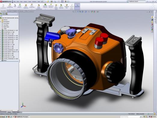
3 i) Introductory presentation SolidWorks Training ii) The SolidWorks GUI The SolidWorks Graphical User Interface (GUI) is shown below. Specifically this is how the GUI looks when using the Part Creation Environment: Command Manager Toolbar - contains all sketch tools and extrude tools - shown with the sketch tab selected. Heads up View Toolbar Useful for changing orientation and appearance of the part that you are drawing FeatureManager Design Tree - where all the sketches and part features are displayed. The second tab on this left hand panel is called the PropertyManager. When using various sketch tools this will automatically be opened. Graphics Area where you sketch in 2D and create 3D parts. PART CREATION ENVIRONMENT Tabs to: - Online tutorials - Part libraries - Part appearances - Custom properties - etc. When in the Part Creation Environment, the Features menu tab of the Command Manager toolbar changes to the following: When we move to the Assembly Environment, the Command Manager changes to the following When we move to the Drawing Environment, the Command Manager toolbar becomes this: Rev /03/2017 Page 1
.")
4 iii) Setting-up customised SolidWorks tools Before starting we are going to set up the SolidWorks software with several customised tools that are useful in design created in the School of Physics & Astronomy. These custom tools allow for parts to be drawn up with additional custom properties that are automatically linked to and displayed on engineering drawings (more detail later!). Open a web browser and go to Download the UGL Tools zip file to C:\Users\yourname\Documents\ then extract the files (right click on zip file and select Extract All ) Open SolidWorks Select the Options menu as shown below (this menu can also be found under Tools>Options) Select File Locations from the right hand menu tree. Under the drop down menu entitled Show folders for: pick Document Templates and then Add to add a link to the folder called C:\Users\yourname\Documents\ Repeat this for the following categories in the drop down menu: - Document Templates - BOM Templates - Custom Property Files [Delete the default folder before adding a new folder link] - Drafting Standards Rev /03/2017 Page 2


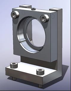
5 - Sheet formats TUTORIAL PART 1 - Creating Parts The first tutorial is an exercise that demonstrates the most commonly used functions when creating a 3D solid part. We are going to create a simple optic holder, shown below-left, which will form part of an optical mount assembly shown in the picture below-right. Optic Holder Optical Mount Assembly 1.1 Open a new part file as shown below (or via File>New) 1.2 Select Advanced using the bottom right hand corner button then UGL_SW_Templates_Etc A new part window shall open with the most commonly used tools in the tool bar, named the Command Manager along the top of the screen. Rev /03/2017 Page 3


6 1.3 From the Command Manager Toolbar, select the Sketch tab (see below) 2 Drawing the Part 2.1 Select the Sketch tool. Three planes should now be shown in the main drawing window (as per the figure below). 2.2 By selecting the front plane, the view should rotate such that the front plane is facing you and you are now effectively drawing in 2D. Rev /03/2017 Page 4


7 2.3 Select the Rectangle tool. Notice that there are several options on how to draw the rectangle shown in the PropertyManager panel on the left hand side of the GUI. We will select the Center Rectangle tool. 2.4 Hover the cursor over the origin point and using the left mouse button (press once but do not hold) select the red origin point of the sketch, pull out a rectangle of any size by moving the mouse laterally, then click the left mouse button again to complete the action. Should you draw something that you do not wish to have, press Escape to exit the rectangle tool. The unwanted sketch can be deleted by dragging the cursor across the rectangle using the left mouse button, then pressing Delete on your keyboard. Alternatively individual lines of the sketch may be selected using the mouse and Deleted one by one. 2.5 We are now going to define the line lengths of the sketch by dimensioning each line. Select the Smart Dimension tool Rev /03/2017 Page 5


8 2.6 Select the vertical line in your sketch, drag out the dimension so that you can see both the line and the dimension clearly, and then click the left mouse button. A small Modify window shall pop up allowing you to enter a dimension. Enter 35mm. 2.7 Repeat for the horizontal dimension and again enter 35mm as the length. To close the Dimension Tool, either press the green tick at the top left corner of the PropertyManager panel, or simply press the Esc button on the keyboard. Now that we have defined our overall dimensions in 2D we now want to add the 3 rd dimension to create a solid part. To edit a dimension, if it needs to be changed or was entered incorrectly, simply double click on the number in the graphics area and enter the correct dimension. 2.8 Select the Features tab from the CommandManager Toolbar along the top of the SolidWorks window. Then select Extruded Boss/Base. Rev /03/2017 Page 6


9 The part should rotate to an Isometric view with a silhouette of the solid part. By default the part thickness value in the PropertyManager panel is set to 10mm. This should be changed to 6mm and also Mid Plane should be selected from the drop down menu instead of Blind Rev /03/2017 Page 7
 to leave a solid cube of dimensions 3 Circular holes 3.1 Select the front face of the cube with the left mouse button.")
10 To confirm the action, click the green tick (either in the PropertyManager panel or in the top right hand corner of the Graphics Area 35x35x6mm. ) to leave a solid cube of dimensions 3 Circular holes 3.1 Select the front face of the cube with the left mouse button. (Notice how a face is highlighted with an orange outline as you pass the mouse over it). 3.2 Select the Sketch tab from the CommandManager toolbar and then select Sketch. A new sketch shall be started on the front face of the cube. 3.3 Select the Circle tool and draw a circle, centred on the red origin on the front face of the cube. Again, the circle can be dragged to any size we will define this by adding a dimension, next. 3.4 Exit the Circle tool by pressing Escape or the green tick in the PropertyManager panel. 3.5 Select the Smart Dimension tool and dimension the circle with diameter 27mm. Rev /03/2017 Page 8
. 3.")
 will achieve the same end result, it is better in this instance to use the Through All action in case you wish to change the thickness of the part at a later stage. 3.")
11 3.6 Now, to make a circle-shaped cut through the part, select the Features tab in the Command Manager toolbar, then select the Extruded Cut tool. The circle should now have a silhouette of a hole removed from the cube (as per figure below right). 3.7 In the PropertyManager panel, under the top drop down menu in Direction 1, change the hole from being Blind (and 6mm long) to going Through all Whilst this action (changing it to Through All rather than Blind/6mm) will achieve the same end result, it is better in this instance to use the Through All action in case you wish to change the thickness of the part at a later stage. 3.8 Rotate the part to show the reverse side of the cube. As a reminder, the part can be rotated by pressing and holding the middle mouse button and moving the mouse. Zooming in or out can be done by scrolling the middle mouse button. Rev /03/2017 Page 9


12 3.9 Now select the back face of the part and select the sketch tool under the sketch tab of the Command Manager toolbar Sketch two concentric circles with different diameters centred on the red origin of the back face of the part Using the Smart Dimension tool, dimension the smaller of the circles with a diameter of 21mm, after which exit the Smart Dimension tool. The second circle is to be identical in diameter to the cylindrical bore through the part. There are two possibilities for this, either a dimension made be applied exactly the same as the diameter of the circular bore or, much better, particularly if the part may change size at a later stage, a Relation may be added to match the diameter of the bore feature to the circular sketch. To add a relation, do the following: 3.12 Select the edge of the circular bore and then, whilst holding down the Ctrl button on your keyboard, select the second circle in the sketch. Notice that a Properties area will open in the PropertyManager in the left hand panel. Rev /03/2017 Page 10


13 3.13 In the Add Relations sub-section of the PropertyManager, select the Coradial relation. The sketched circle should now sit coradial to the edge of the bore hole and will have changed colour from blue to black. This line colour change indicates that the circle is fully defined Now, extrude these two circles 1mm in towards the part (i.e. so that this does not protrude from the part). To see this better the part should be rotated as per the right hand figure above. The direction of the extruded sketch may be reversed by using the reverse direction button in the PropertyManager panel Confirm the action by clicking the green tick. This is probably a good time to Save your work. Save the file as Optic_Holder.sldprt in the folder that you created at the start of the tutorial. Rev /03/2017 Page 11
 screw. 4.")


14 4 Sketches with Construction Lines We are now going to add two features that form the two points in the kinematic mount for our optic. The third point in this three point mount shall be defined by a grub (or set ) screw. 4.1 Select the front face of the cube, and draw on it one small circle at approximately 7 o clock and with the centre of the circle aligned with the circular edge of the large bore hole. If the small circle is drawn without its centre point being aligned to the circular edge of the bore, this can be realigned by selecting both the edge of the bore hole and the circle centre, whilst holding down the Ctrl button, and adding a coincident relation. 4.2 Additionally draw two centerines. The first should be from the centre of the small circle that you have just drawn to the origin of the part, then a second line from the origin down to the edge of the bore (at 6 o clock). Double click away from the part to stop sketching lines. Rev /03/2017 Page 12


15 4.3 Now, in the same sketch, add a circular sketch centred on the part origin. 4.4 Additionally, change the line to being a construction line by checking the box in the Circle PropertyManager menu. 4.5 Dimension this circle to be 25.4mm. This dashed, circular construction line simulates the position where a one inch cylindrical optic will sit in the optic holder. We shall use this construction line to help us define the kinematic features around the optic, to be the correct size. 4.6 Now, to define the diameter of kinematic contact point, the small circle should be aligned tangentially with the 25.4mm diameter construction line. To do so, select both the small circle and the construction circle (hold down the Ctrl button) and set a Tangent relation. 4.7 Finally, dimension the angle between the two straight centrelines as 60 degrees. All lines in your sketch should now be black identifying that they are all fully defined. Rev /03/2017 Page 13


 and then select the internal cylindrical face of the first")
16 4.8 Next, extrude a solid cylinder using the small circle up to the lip on the hole. To do so, select Extrude Boss/Base from the Features toolbar and extrude Up to Surface, selecting the surface now at the base of the bore. You may wish to rotate the part to make it easier to see which direction of the extrusion. 5 Patterning Features The first of the two contact point features of the isostatic mount is now in place. This feature could simply be mirrored in the sketch or mirrored as a Feature however, to introduce another useful tool, for the second we will use the Circular Pattern tool. To aid the use of this tool a reference Axis will be added to the 3D part to pattern our feature around. 5.1 Select the Axis tool (under the Reference Geometry drop-down menu) and then select the internal cylindrical face of the first bore that was cut from the part. SolidWorks should automatically select the correct tool function to create an axis down the centre of the bore, as highlighted in the figure below right. Rev /03/2017 Page 14
, and")


17 5.2 Now, in the FeatureManager Design tree, select both the last feature that was made and the new Axis (Use the Shift or Ctrl key to select both items), and then open the Circular Pattern tool. Automatically SolidWorks shall preview several further identical features. 5.3 In the Circular Pattern tool, change the number of instances to 3, select Equal Spacing, and also, under Instances to Skip, select the node at the top of the part (as shown below). Rev /03/2017 Page 15


18 6 Adding holes with the Hole Wizard Now we will add a threaded hole to the top face of the optic holder. 6.1 Select the top face of the part and rotate the part such that that top face is pointing towards you (press the Space-bar and click the Normal To or Top View button). 6.2 Next, open the Hole Wizard tool in the Features toolbar. A menu will open up in the FeatureManager Design Tree with a number of options allowing you to draw a variety of hole types from a large library within SolidWorks. We want to draw a tapped M3 hole so this can be selected by clicking the Straight tap button and selecting M3 from the drop down menu under Hole Specification. Additionally, under the End Condition for the hole, we wish the hole to go Up To Next and it should be tapped Up To Next also. Menu upper half Menu lower half. 6.3 Next, select the Positions tab at the top of the PropertyManager panel and then press click once on the part origin to place a point at the centre of the top face. After that, click the green tick to confirm the action and exit the tool. Rev /03/2017 Page 16
 on your sketch with the cursor and delete (either by pressing delete on your keyboard, or right-clicking and selecting delete from the pop-up menu).")


19 If you happen to have created two or more point sketches on the top surface, to remove the extra points first deselect the Point tool by clicking on the button in the Sketch toolbar then, secondly, select the supplementary point(s) on your sketch with the cursor and delete (either by pressing delete on your keyboard, or right-clicking and selecting delete from the pop-up menu). We are now going to add two further clear holes on the front face of the part that are used to attach the optic holder part to its bracket. Clear holes are those that give a clearance to a threaded bolt or screw, e.g. a normal clear hole for an M3 screw is 3.4mm in diameter. 6.4 Select the front face of the part and open the Hole Wizard tool, this time selecting the Hole Type as Hole. Under the Type: drop-down menu select Screw clearances and finally make the hole size M3 and give it a Through all End Condition. 6.5 In the PropertyManager panel, select the top tab marked Positions. Add two points on the front face of the part then deselect the point tool by clicking on the Point button in the Sketch toolbar. 6.6 Now we are going to define the location of these holes by adding dimensions. Select the Smart Dimension tool in the picture below. and then dimension to the holes with respect to the edges shown Rev /03/2017 Page 17


20 Note that the right hand point is still blue in colour. This is because it is not yet fully defined. This could be defined by adding a further dimension but a better way to do this is to co-align the point horizontally with the left hand point that is already defined in this direction. 6.7 To align the holes horizontally, deselect the smart dimension tool and select both of the points whilst holding down the Ctrl key. The relations menu will now appear in the Feature Manager Design tree and a Horizontal relation should be selected. 6.8 Complete the Hole Wizard action by clicking the green tick. 7 Finishing Touches As a finishing touch to the part, and a useful thought towards the manufacturability of it, we will add a radius, or fillet, at the edges of the two isostatic features of the optics mount. This is a simple operation using the Fillet tool. 7.1 Select the Fillet tool. Change the radius of the fillet to 1mm. then select the four edges. You will need to rotate the part to access each of the edges to be filleted. 7.2 The part is now complete. Save the part as Optic_Holder.sldprt in the assigned folder in C:\Users\yourname\Documents\. END OF TUTORIAL PART 1 Rev /03/2017 Page 18

21 TUTORIAL PART 1 Extras A.1 Adding Custom Properties When creating the parts or assemblies it is possible to add properties to the part. These properties will subsequently show in the engineering drawings. A.1.1 Select the Custom Properties tab from the right hand tabs on the SolidWorks GUI. Then fill in the tabs with the appropriate information. A.1.2. The drawing number should be an alphanumeric code of 10 digits or less that will allow you to easily and quickly identify you part if it is out for manufacture. A.2 Applying Materials Under the FeatureManager Design Tree, you will notice that there is an area for adding a material to the part (see picture overleaf). This is a useful tool such that material information can be displayed on engineering drawings or if the mass of the part is required. By right-clicking on Material <not-specified> you can bring up a pop-up menu, and from there you can add a multitude of materials. Rev /03/2017 Page 19

 Rev 2.")
22 A.3 Draw up the bracket for the optic holder Using the tools learned in Part 1, draw the Optic Holder Bracket below: (More pictures and dimensions overleaf) Rev /03/2017 Page 20


23 Hint: Draw L-profile on the right plane then do a mid-plane extrude Hint: Cut a rectangular hole, then create fillet to radius the bottom two edges of the hole. Rev /03/2017 Page 21


24 x M3 Tapped holes 5mm down, 27mm between them. 2 x M3 Clearance holes - 4mm in, 25mm between them 5 25 Save this as Optics_Mounting_Bracket.sldprt A.4 Draw up a one inch optic 6.35 Hint: Chamfer edges 0.1mm. Apply a material glass. Save this as: One_Inch_Optic.sldprt A.5 Add Custom Properties to the parts Add custom properties to the mounting bracket and one inch optics parts. Now, progress to Tutorial Part 2. Rev /03/2017 Page 22

25 TUTORIAL PART 2 Assemblies SolidWorks Assembly Environment interface is very similar to the Part Creation interface, however the tools are somewhat different. Whilst it is possible to create parts and sketches within this environment it is not typical to do this so the main toolbars that you will use in this section will concentrate on manipulating pre-existing parts such that can be aligned or mated together to form a visual representation of an assembled mechanism. 1.1 Open a New Assembly, in the same manner as you opened a part previously, only selecting UGL_Assembly this time around. As you begin in the Assembly Environment SolidWorks will automatically prompt (in the left hand PropertyManager Panel) to open a Part or Assembly to Insert. 1.2 Browse for the first part of you assembly called Optics_Mounting_Bracket.sldprt 1.3 Click Open and then click the green tick button to confirm the action. This will fix the part to the assembly axis. Rev /03/2017 Page 23


26 1.4 Next we would like to bring the second part in to our assembly. To do so, select the Insert components tool from the Command Manager toolbar. 1.5 Again, Browse to find the Optic_Holder part and insert it anywhere in the assembly. Note that the part in its current unconstrained state may be dragged anywhere on the screen with by clicking and holding the left button of the mouse. Notice too that the part can be placed such that it interferes with the bracket, as per the figure below. 2 Mating Parts Now we are going to define the position of the optic holder with respect to the bracket using the Mate function. 2.1 Select Mate from the CommandManager toolbar. 2.2 Select both the front vertical (U-shaped) face of the bracket and the back face of the optic holder. You will need to rotate the assembly to select the back face of the optic holder. Notice that the part automatically moves to align the faces of the two parts. Also notice that in the PropertyManager panel, SolidWorks has automatically selected a Coincident Mate which is the correct Mate here. Click the green tick to confirm the action. Rev /03/2017 Page 24


27 Now we are going to align the screw holes that we created such that the assembly is fully constrained. 2.3 Using the Mate tool, select the cylindrical bore of one of the tapped holes in the bracket part. Also, select the corresponding cylindrical bore in the optic holder. 2.4 Again the parts should move together automatically and SolidWorks shall select the most likely Mate type in this case a Concentric Mate. 2.5 With one Mate remaining you can now grab and pivot the optic holder about the bracket by left-clicking and trying to pull it away from the bracket. The optic holder should rotate about the one constrained hole and in plane with the front face of the bracket. Doing this will make it easier to see both of the remaining, unconstrained holes. 2.6 Finally, to Mmate the two remaining holes on the optic holder and bracket, select each one of them and again add a Concentric Mate. Rev /03/2017 Page 25

28 3 Adding screws 3.1 SolidWorks has a large library of standard parts which can be found under the design library in the (hidden) right-hand window panel. 3.2 By selecting the Design Library tool and then the Toolbox Icon you can find a large array of bolts, washers and other mechanical parts for many different international standards. BSI or ISO Metric standards are the most commonly used in the School of Physics & Astronomy. Those who work on US projects, such as LIGO, may however adopt the ANSI Inch system. 3.3 Go to the ISO section of the design Library, select Bolts and Screws > Hexagon Socket Head Screws > Hex Socket Head ISO Press and drag the icon across on to the graphics area, adjacent to one of the two holes bolt holes. When an impression of a screw shows then let go of the mouse button. A menu will open in the PropertyManager panel with an interface to adjust the screw to your required size. M3 x 12mm should be suitable for your assembly. Rev /03/2017 Page 26


29 3.5 Once the first screw has been added (confirming by clicking the green tick), SolidWorks will automatically give you another screw of an identical size to be added to the assembly. Add this screw by hovering over the second screw hole. 3.6 Repeat this action to add two more screws in the two holes on the base of the bracket (these are for attaching the bracket to an optical bench). To finish, click the red cross or press the Esc key. 3.7 We now want to add a set-screw for holding the optic in place so through the design library select an ISO Socket Set-screw with a cone point and insert it in the threaded hole at the top of the optic holder. It is best to hover the part over the central bore of the hole on this occasion and it may be beneficial to rotate your assembly and zoom-in so that you can easily highlight the hole. Again, to finish, click the red-cross. Rev /03/2017 Page 27

30 PART 2 Extras B.1 Add the One Inch Optic to the assembly. Trying first mating using the concentric mate with the large bore of the optic holder. Secondly, suppress or delete that concentric mate and try using tangential mates with the two isostatic mount features (MORE DIFFICULT!) then a second mate between the tip of the set-screw and the barrel face of the optic. 4 B.2 Adding Custom Properties. As per in the parts we can add custom properties that are displayed on the engineering drawing. END OF TUTORIAL PART 2 Rev /03/2017 Page 28

31 TUTORIAL PART 3 Exporting to ANSYS, CAM or for 3D printing It is relatively simple to export from SolidWorks for use in other programs. SolidWorks has a number of file translation programs built in to it. 1.1 Exporting to ANSYS If you have both SolidWorks and ANSYS installed on your machine, there are two ways of exporting in to ANSYS For ANSYS Workbench, the cleanest way to export is by opening ANSYS directly from SolidWorks. There is an ANSYS add-in in SolidWorks which can be activated by going to the Tool> Add-Ins menu For ANSYS Classic and ANSYS Workbench on a machine that does not have SolidWorks installed, the SolidWorks part or assembly can be saved as a.sat file by simply using the File>Save As function. 1.2 Exporting for Computer Aided Manufacture (CAM) or 3D Printing For CAM manufacture, files should be saved as STEP, IGS, STL or DXF. Note that DXF is a 2D format so you will be asked which view of the 3D part that you would like to export (i.e. TOP, SIDE, BACK, FRONT, etc). An STL file is a 3D format commonly used in 3D printing. Notes: - Material properties from SolidWorks shall not automatically transfer to ANSYS. - Make sure, if exporting as.sat file the settings are such that the export is completed in meters, otherwise the part/assembly will come in to ANSYS with the wrong scale. The settings can be found as you Save the part as a.sat file. - It is good practice to check that your exported file has been created correctly. This can simply be done by reopening it in SolidWorks. END OF PART 3 Rev /03/2017 Page 29
32 TUTORIAL PART 4 Engineering Drawings The engineering drawing is an important document that allows your part to be manufactured to the dimensions, tolerances and finish standards that you require. All jobs submitted to a manufacturer, whether this is done electronically using a 3D solid model file format (sldprt, SAT, IGES, STEP), an engineering drawing should also be supplied. The problem with 3D solid model formats is that they do not typically contain information about dimensions or tolerances so for example, if a file translates incorrectly or if a manufacturer uses a different tolerance level to what you require, you may end up with a part that does not have the same dimensions that you had intended it to have. SolidWorks makes engineering drawings relatively easy as it recognises the various international drawing standards such as ISO (International), BSI (British), ANSI (American), DIN (German), JIS (Japanese), etc. These can be set-up in the SolidWorks Options menu but typically for the work done in the School we will use the ISO standard. All engineering drawings should have at least three views, e.g. front, top and one side view, but given that you have created a 3D model it is useful to add an Isometric view of the part too to make it easier for the manufacturers to visualise. 1 Starting an engineering drawing There are two ways of beginning an engineering drawing: 1.1 Go to File>New> (or ) and select the UGL_A4_landscape (or UGL_A3_landscape) document. Then on the right hand panel of your screen select the View Pallet tab and browse for the part that you want to draw. Front, Top, Side views of the part you select should now appear in the right hand panel. You should now drag and drop one of these views on to your drawing sheet and then other views will automatically appear from this view. OR 1.2 the second way of starting a drawing is if you already have a part open is as follows: 1.3 Go to File>Make Drawing from Part/Assembly (or from the drop down menu), select the drawing type that you want and then the views should open up automatically in the right hand panel. As per the first method for beginning a drawing, drag one of these views on to the drawing and then layout the other views that you require. Rev /03/2017 Page 30


33 The View Palette panel drag and drop views from here Front view and auxiliary views laid out on the drawing sheet You are now ready to begin dimensioning you part. The key to dimensioning any part is not to over-dimension make sure that the position of all features are determined from one clear datum but do not dimension to the same feature twice! Also, make sure that the drawing has been completed on the correct size of paper for the part or assembly if what you are drawing up has many fine details, scale up and use a larger drawing size, or use detail views to show fine detail. Before submitting an engineering drawing for manufacture it is always best to have it checked by an experienced engineer or draftsman to be sure that all dimensions and details have been included. Rev /03/2017 Page 31


34 2 Adding linear dimensions 2.1 Linear dimensions are added like they are in the part creation environment of SolidWorks. Select Smart Dimension from the Annotation menu of the Command Manager toolbar. Now, simply select edges, vertices or centrelines to add dimensions to you part. If you want to add a tighter tolerance than those shown in the General Tolerances in the title area of the drawing this can be done in the following way: 2.2 Firstly deselect Smart Dimensions and select a line or feature to be dimensioned. When selected, you will notice that a set of tools will appear in the PropertyManager panel. 2.3 Under Tolerance/Precision there are two pull down menus, the first of which allows you to choose a variety of tolerance types. Most commonly used are Symmetric or Bilateral which essentially let you set how much you would like to have the part over and under the nominal size. Lets say for this part our height is very critical so we shall set a bilateral tolerance of +0.1, 0.0, as shown here: Once the linear dimensions have been added the drawing should look something like the figure below: Rev /03/2017 Page 32


35 Drawing with Linear Dimensions added 3 Adding radial or angular dimensions Adding radial or angular dimensions works in the same manner as adding linear dimensions as SolidWorks, essentially, will know if the line that you select requires a radial or angular dimension. We may, however need to add some extra centre marks and construction lines to define the angles between the parts. 3.1 Radial Dimensions Select the Smart Dimension tool and then select the inner bore hole and drag out the dimension such that it is clear to read at the side of the part. Rev /03/2017 Page 33


36 3.1.1 The next, larger bore hole with the isostatic features. You will notice when you try to dimension this a radius appears rather than a diameter this is because it is not a complete cylinder. Whilst having a radius dimension here is okay, we can change this to a diameter for more clarity by selecting the dimension (it should turn green) and then in the LHS panel, select the Leaders tab, and then the diameter button The sketch should now look like this: 3.2 Angular dimensions To dimension the two features that make up two of three points of our isostatic mount we need to add some centre marks. As these have cylindrical profiles on their outer surface, we can apply centre marks and by using the correct tool we can include circular construction lines and radial lines that can then be dimensioned Select the Centre Mark tool under Annotation of the Command Manager toolbar. In the left hand panel, select the Circular Centre Mark tool. Rev /03/2017 Page 34
 and then select the propagate icon that")


37 3.2.2 Now, select the outer edge of isostatic mount feature (you may wish to zoom-in to make sure you catch the correct edge) and then select the propagate icon that appears above the centre mark you have inserted, to make your radial centre marks. -> Press the green tick to confirm the action You may now dimension to the radial lines of these features to show what angle they are positioned with respect to the vertical centre line of the large bore. To do so, select smart dimension and then select both the vertical line and the radial line. This should now pull out a dimension of a 60 degree angle Repeat this for the opposing angled line. Rev /03/2017 Page 35
. 4.1")

38 4 Section and Detail Views Now that there are a number of dimensions on this view of the drawing the kinematic points are quite hidden behind the dimensions. For dimensioning these smaller features it is best to add a Detail View (a zoomed-in view of a small area of the drawing). 4.1 Detail Views To add a detail view click the View Layout tab in the Command Manager Toolbar and then find the Detail view tool. Now, with this tool, draw a circle over the isostatic mount point and then drag the detail view in to free space. SolidWorks will choose the scale for you however if you prefer something different, this can be edited in the left hand panel Now add dimensions to this view using the smart dimension tool. Again, for clarity you should add a centre mark in the detail view, too To save doing a second detail view for the opposing isostatic point you may add the note 2x to your dimensions in your first detail view. This will be interpreted accordingly by the manufacturer. Rev /03/2017 Page 36


. 4.2.2 Now dimension the thin disk feature.")
39 4.1.4 One detail of our drawing that the manufacturer cannot see from the three views of the optic holder, is the thin disk at the base of the hole. To highlight and dimension this feature we can use a cross-section tool. 4.2 Section Views To add a section view click the View Layout tab in the Command Manager Toolbar and then find the section view button. Next, using this tool, draw a vertical line from a little above the centre point of the top edge of the front view, to a little below the bottom edge of the front view (see below) Now dimension the thin disk feature. Centrelines should be added to show the cylindrical profiles in the section view. Rev /03/2017 Page 37


40 5 Dimensioning holes created using the Hole Tool Three holes were created using the hole tool in this part. By doing so, SolidWorks adds the necessary detail on the engineering drawing for the hole to be manufactured appropriately. To display this information we use the Hole Callout tool of the Command Manager. under the Annotation Tab 5.1 Select the Hole callout tool. Select the hole at the top of the part. Drag the dimensional instruction out to a clear area on your drawing sheet. 5.2 Repeat for the one of the two holes on the front face of the part. Note that as both of these holes were created together and are of the same size, SolidWorks groups the instruction for them in one annotation. 6 Adding Custom Properties Like when creating the parts and assemblies, from the right hand tabs on the SolidWorks GUI you may add custom properties to the engineering drawing that shall automatically fill-in to the fields in the title area. 6.1 Click the Custom Properties Tab, and fill in all details. Notice that when the fields are filled in they appear in the title area. Menu split in two Rev /03/2017 Page 38


41 7 Final touches The drawing is finished as far as the dimensioning and detailing is concerned but there are a couple of things that can be done to make things even clearer. Firstly we will change the isometric view to give it solid colour and secondly we will change the colour of the centre lines to make them stand out a little better. 7.1 Select the Isometric view, and then select the Display style icon at the top of the drawing area. 7.2 Pull down the Display style menu and change it to the solid colour with lines. The Isometric view shall now look solid making it easier for a manufacturer to understand the geometry. 7.3 To change the centre line format we firstly need to open a new toolbar. To do so, right click any menu area and select the Line format toolbar to Tools>Customize and open the toolbar this way). (alternatively, go 7.4 Now select all of the centrelines, you should hold the shift button down as you do this. Then, finally, select the line colour icon red. and change the centre marks and lines to, for example, 7.5 Lastly, change all dimensions to blue (if they are not already). Your drawing is now complete. And should look like this (see below): Rev /03/2017 Page 39


42 8 Drawings of Assemblies Assembly drawings do not need to have quite so much detail as part drawings. This is because, in general they are not used for manufacture and are more there to show the overall layout and assembly of the parts in a formal manner. The drawing below gives an example of how an Assembly drawing should look. Rev /03/2017 Page 40


43 Notice that all dimensions are shown with parentheses (brackets) to signify that they are reference dimensions and are not to be used to manufacture the parts. These parentheses added from the left hand side bar when the dimensions are added to the drawing. can be 9 Changing the drawing scale SolidWorks automatically chooses a drawing scale for the parts on the drawing. Should the drawing scale not be best suited to the parts/assemblies being dimensioned this can be changed in the following way. 9.1 Right click Sheet1 in the FeatureManager Design Tree. Select Properties and then change the scale in the pop up window. END OF TUTORIAL PART 4. Rev /03/2017 Page 41
Engineering Technology
 Engineering Technology Introduction to Parametric Modelling Engineering Technology 1 See Saw Exercise Part 1 Base Commands used New Part This lesson includes Sketching, Extruded Boss/Base, Hole Wizard,
Toothbrush Holder. A drawing of the sheet metal part will also be created.
 Prerequisite Knowledge Previous knowledge of the following commands is required to complete this lesson; Sketch (Line, Centerline, Circle, Add Relations, Smart Dimension,), Extrude Boss/Base, and Edit
Shaft Hanger - SolidWorks
 ME-430 INTRODUCTION TO COMPUTER AIDED DESIGN Shaft Hanger - SolidWorks BY: DR. HERLI SURJANHATA ASSIGNMENT Submit TWO isometric views of the Shaft Hanger with your report, 1. Shaded view of the trimetric
SolidWorks Part I - Basic Tools SDC. Includes. Parts, Assemblies and Drawings. Paul Tran CSWE, CSWI
 SolidWorks 2015 Part I - Basic Tools Includes CSWA Preparation Material Parts, Assemblies and Drawings Paul Tran CSWE, CSWI SDC PUBLICATIONS Better Textbooks. Lower Prices. www.sdcpublications.com Powered
Introduction to Sheet Metal Features SolidWorks 2009
 SolidWorks 2009 Table of Contents Introduction to Sheet Metal Features Base Flange Method Magazine File.. 3 Envelopment & Development of Surfaces.. 14 Development of Transition Pieces.. 23 Conversion to
Digital Camera Exercise
 Commands Used New Part This lesson includes Sketching, Extruded Boss/Base, Extruded Cut, Fillet, Chamfer and Text. Click File, New on the standard toolbar. Select Part from the New SolidWorks Document
Engineering & Computer Graphics Workbook Using SOLIDWORKS
 Engineering & Computer Graphics Workbook Using SOLIDWORKS 2017 Ronald E. Barr Thomas J. Krueger Davor Juricic SDC PUBLICATIONS Better Textbooks. Lower Prices. www.sdcpublications.com Powered by TCPDF (www.tcpdf.org)
Engineering & Computer Graphics Workbook Using SolidWorks 2014
 Engineering & Computer Graphics Workbook Using SolidWorks 2014 Ronald E. Barr Thomas J. Krueger Davor Juricic SDC PUBLICATIONS Better Textbooks. Lower Prices. www.sdcpublications.com Powered by TCPDF (www.tcpdf.org)
AEROPLANE. Create a New Folder in your chosen location called Aeroplane. The four parts that make up the project will be saved here.
 AEROPLANE Prerequisite Knowledge Previous knowledge of the following commands is required to complete this lesson. Sketching (Line, Rectangle, Arc, Add Relations, Dimensioning), Extrude, Assemblies and
Lab 3 Introduction to SolidWorks I Silas Bernardoni 10/9/2008
 1 Introduction This lab is designed to provide you with basic skills when using the 3D modeling program SolidWorks. You will learn how to build parts, assemblies and drawings. You will be given a physical
Beginner s Guide to SolidWorks Alejandro Reyes, MSME Certified SolidWorks Professional and Instructor SDC PUBLICATIONS
 Beginner s Guide to SolidWorks 2008 Alejandro Reyes, MSME Certified SolidWorks Professional and Instructor SDC PUBLICATIONS Schroff Development Corporation www.schroff.com www.schroff-europe.com Part Modeling
SolidWorks Design & Technology
 SolidWorks Design & Technology Training Course at PHSG Ex 5. Lego man Working with part files 8mm At first glance the Lego man looks complicated but I hope you will see that if you approach a project one
SolidWorks 2005 Tutorial. and MultiMedia CD. A Step-by-step Project Based Approach Utilizing 3D Solid Modeling
 INSIDE: MultiMedia CD An audio/visual presentation of the tutorial projects SolidWorks 2005 Tutorial and MultiMedia CD A Step-by-step Project Based Approach Utilizing 3D Solid Modeling David C. Planchard
SolidWorks 103: Barge Design Challenge
 SolidWorks 103: Barge Design Challenge Note: This tutorial was created using SolidWorks 2009. If you are using another version of SolidWorks, you may notice some variation in display states and configuration.
Foreword. If you have any questions about these tutorials, drop your mail to
 Foreword The main objective of these tutorials is to give you a kick start using Solidworks. The approach to write this tutorial is based on what is the most important knowledge you should know and what
SOLIDWORKS 2015 and Engineering Graphics
 SOLIDWORKS 2015 and Engineering Graphics An Integrated Approach Randy H. Shih SDC PUBLICATIONS Better Textbooks. Lower Prices. www.sdcpublications.com Powered by TCPDF (www.tcpdf.org) Visit the following
and Engineering Graphics
 SOLIDWORKS 2018 and Engineering Graphics An Integrated Approach Randy H. Shih SDC PUBLICATIONS Better Textbooks. Lower Prices. www.sdcpublications.com Powered by TCPDF (www.tcpdf.org) Visit the following
Computer Aided Design Module 2. Lesson Toblerone Bar
 Computer Aided Design Module 2 Lesson Toblerone Bar Lesson? Toblerone Bar New Commands used: Polygon, Add Relations, Smart Dimension, Extrude Boss/Base (Mid Plane), Fillet, Line, Extrude-Cut, Linear Pattern
Engineering Design. with SolidWorks A Step-by-Step Project Based Approach Utilizing 3D Solid Modeling
 INSIDE: MultiMedia CD An audio/visual presentation of the tutorial projects Engineering Design with SolidWorks 2010 A Step-by-Step Project Based Approach Utilizing 3D Solid Modeling Introductory Level
Below are the desired outcomes and usage competencies based on the completion of Project 4.
 Engineering Design with SolidWorks Project 4 Below are the desired outcomes and usage competencies based on the completion of Project 4. Project Desired Outcomes: An understanding of the customer s requirements
SolidWorks 95 User s Guide
 SolidWorks 95 User s Guide Disclaimer: The following User Guide was extracted from SolidWorks 95 Help files and was not originally distributed in this format. All content 1995, SolidWorks Corporation Contents
Solidworks: Lesson 4 Assembly Basics and Toolbox. UCF Engineering
 Solidworks: Lesson 4 Assembly Basics and Toolbox UCF Engineering Solidworks We have now completed the basic features of part modeling and it is now time to begin constructing more complex models in the
Introduction to Autodesk Inventor for F1 in Schools (Australian Version)
") Introduction to Autodesk Inventor for F1 in Schools (Australian Version) F1 in Schools race car In this course you will be introduced to Autodesk Inventor, which is the centerpiece of Autodesk s Digital
Introduction to Autodesk Inventor for F1 in Schools (Australian Version) F1 in Schools race car In this course you will be introduced to Autodesk Inventor, which is the centerpiece of Autodesk s Digital
Introduction to CATIA V5
 Introduction to CATIA V5 Release 17 (A Hands-On Tutorial Approach) Kirstie Plantenberg University of Detroit Mercy SDC PUBLICATIONS Schroff Development Corporation www.schroff.com Better Textbooks. Lower
Introduction to Circular Pattern Flower Pot
 Prerequisite Knowledge Previous knowledge of the sketching commands Line, Circle, Add Relations, Smart Dimension is required to complete this lesson. Previous examples of Revolved Boss/Base, Cut Extrude,
1. Create a 2D sketch 2. Create geometry in a sketch 3. Use constraints to position geometry 4. Use dimensions to set the size of geometry
 2.1: Sketching Many features that you create in Fusion 360 start with a 2D sketch. In order to create intelligent and predictable designs, a good understanding of how to create sketches and how to apply
Introduction to Revolve - A Glass
 Introduction to Revolve - A Glass Design & Communication Graphics 1 Object Analysis sheet Design & Communication Graphics 2 Prerequisite Knowledge Previous knowledge of the following commands are required
Introducing SolidWorks
 Introducing SolidWorks SAAST Robotics 2008 SolidWorks Software Visually-based 3-D Mechanical design software Engineers and Designers use it to: Quickly sketch out ideas Experiment with features, dimensions
Veerapandian.K Mechanical Engg Vedharanyam A manual to mechanical designers How Solid works Works?
 Compiled by Veerapandian.K Mechanical Engg Vedharanyam-614 810 A manual to mechanical designers How Solid works Works? Solid works Overview Solid works main idea is user to create drawing directly in 3D
for Solidworks TRAINING GUIDE LESSON-9-CAD
 for Solidworks TRAINING GUIDE LESSON-9-CAD Mastercam for SolidWorks Training Guide Objectives You will create the geometry for SolidWorks-Lesson-9 using SolidWorks 3D CAD software. You will be working
Sash Clamp. Sash Clamp SW 2015 Design & Communication Graphics Page 1.
 Sash Clamp 1 Introduction: The Sash clamp consists of nine parts. In creating the clamp we will be looking at the improvements made by SolidWorks in linear patterns, adding threads and in assembling the
Introduction to SolidWorks Introduction to SolidWorks
 Introduction to SolidWorks Introduction to SolidWorks SolidWorks is a powerful 3D modeling program. The models it produces can be used in a number of ways to simulate the behaviour of a real part or assembly
SDC. SolidWorks Tutorial 2001Plus. A Competency Project Based Approach Utilizing 3D Solid Modeling. David C. Planchard & Marie P.
 2001Plus A Competency Project Based Approach Utilizing 3D Solid Modeling David C. Planchard & Marie P. Planchard SDC PUBLICATIONS www.schroff.com www.schroff-europe.com Project 2 Below are the desired
1. Open the Feature Modeling demo part file on the EEIC website. Ask student about which constraints needed to Fully Define.
 BLUE boxed notes are intended as aids to the lecturer RED boxed notes are comments that the lecturer could make Control + Click HERE to view enlarged IMAGE and Construction Strategy he following set of
Product Modelling in Solid Works
 Product Modelling in Solid Works In the following exercise you will use solid works to construct the computer mouse shown opposite. In this exercise you will use a number of advanced features to achieve
Starting a 3D Modeling Part File
 1 How to Create a 3D Model and Corresponding 2D Drawing with Dimensions, GDT (Geometric Dimensioning and Tolerance) Symbols and Title Block in SolidWorks 2013-2014 By Edward Locke This tutorial will introduce
ME Week 2 Project 2 Flange Manifold Part
 1 Project 2 - Flange Manifold Part 1.1 Instructions This project focuses on additional sketching methods and sketching commands. Revolve and Work features are also introduced. The part being modeled is
Lesson 6 2D Sketch Panel Tools
 Lesson 6 2D Sketch Panel Tools Inventor s Sketch Tool Bar contains tools for creating the basic geometry to create features and parts. On the surface, the Geometry tools look fairly standard: line, circle,
Engineering Design with SolidWorks A Step-by-Step Project Based Approach Utilizing 3D Solid Modeling. David C. Planchard & Marie P.
 Engineering Design with SolidWorks 2003 A Step-by-Step Project Based Approach Utilizing 3D Solid Modeling David C. Planchard & Marie P. Planchard SDC PUBLICATIONS www.schroff.com www.schroff-europe.com
Introduction to 3D CAD with SolidWorks. Jianan Li
 Introduction to 3D CAD with SolidWorks Jianan Li Create a New Part The first time you launch SolidWorks, it asks you to set the default units and dimension standard. Make sure you have IPS and ANSI selected,
Modeling Basic Mechanical Components #1 Tie-Wrap Clip
 Modeling Basic Mechanical Components #1 Tie-Wrap Clip This tutorial is about modeling simple and basic mechanical components with 3D Mechanical CAD programs, specifically one called Alibre Xpress, a freely
Assembly Receiver/Hitch/Ball/Pin to use for CAD LAB 5A and 5B:
 MECH 130 CAD LAB 5 SPRING 2017 due Friday, April 21, 2016 at 4:30 PM All of LAB 5 s hardcopies will be working drawing layouts. Do not print out from the part file. We will be using the ME130DRAW drawing
Ball Valve Assembly. On completion of the assembly, we will create the exploded view as shown on the right.
 Ball Valve Assembly Supplied are the main components of a ball valve. In this exercise you will assemble the valve as shown below Left. (N.B. Socket head cap screws are not supplied these will be created
Lesson 10: Loft Features
 10 Goals of This Lesson Your students will be able to create the following part: profiles chisel This lesson plan corresponds to the Loft Features chapter of SolidWorks Getting Started. SolidWorks Student
On completion of this exercise you will have:
 Prerequisite Knowledge To complete this exercise you will need; to be familiar with the SolidWorks interface and the key commands. basic file management skills the ability to rotate views and select faces
Introduction to Parametric Modeling AEROPLANE. Design & Communication Graphics 1
 AEROPLANE Design & Communication Graphics 1 Object Analysis sheet Design & Communication Graphics 2 Aeroplane Assembly The part files for this assembly are saved in the folder titled Aeroplane. Open an
User Guide V10 SP1 Addendum
 Alibre Design User Guide V10 SP1 Addendum Copyrights Information in this document is subject to change without notice. The software described in this document is furnished under a license agreement or
Evaluation Chapter by CADArtifex
 The premium provider of learning products and solutions www.cadartifex.com EVALUATION CHAPTER 2 Drawing Sketches with SOLIDWORKS In this chapter: Invoking the Part Modeling Environment Invoking the Sketching
Part Design Fundamentals
 Part Design Fundamentals 1 Course Presentation Objectives of the course In this course you will learn basic methods to create and modify solids features and parts Targeted audience New CATIA V5 Users 1
Solidworks Tutorial Pencil
 The following instructions will be used to help you create a Pencil using Solidworks. These instructions are ordered to make the process as simple as possible. Deviating from the order, or not following
Creo Revolve Tutorial
 Creo Revolve Tutorial Setup 1. Open Creo Parametric Note: Refer back to the Creo Extrude Tutorial for references and screen shots of the Creo layout 2. Set Working Directory a. From the Model Tree navigate
Lesson 4 Holes and Rounds
 Lesson 4 Holes and Rounds 111 Figure 4.1 Breaker OBJECTIVES Sketch arcs in sections Create a straight hole through a part Complete a Sketched hole Understand the Hole Tool Use Info to extract information
Understanding Projection Systems
 Understanding Projection Systems A Point: A point has no dimensions, a theoretical location that has neither length, width nor height. A point shows an exact location in space. It is important to understand
Principles and Practice:
 Principles and Practice: An Integrated Approach to Engineering Graphics and AutoCAD 2014 Randy H. Shih Multimedia Disc SDC PUBLICATIONS Better Textbooks. Lower Prices. www.sdcpublications.com Video presentations
< Then click on this icon on the vertical tool bar that pops up on the left side.
 Pipe Cavity Tutorial Introduction The CADMAX Solid Master Tutorial is a great way to learn about the benefits of feature-based parametric solid modeling with CADMAX. We have assembled several typical parts
Inventor-Parts-Tutorial By: Dor Ashur
 Inventor-Parts-Tutorial By: Dor Ashur For Assignment: http://www.maelabs.ucsd.edu/mae3/assignments/cad/inventor_parts.pdf Open Autodesk Inventor: Start-> All Programs -> Autodesk -> Autodesk Inventor 2010
SolidWorks Tutorial 1. Axis
 SolidWorks Tutorial 1 Axis Axis This first exercise provides an introduction to SolidWorks software. First, we will design and draw a simple part: an axis with different diameters. You will learn how to
g. Click once on the left vertical line of the rectangle.
 This drawing will require you to a model of a truck as a Solidworks Part. Please be sure to read the directions carefully before constructing the truck in Solidworks. Before submitting you will be required
Name: Date Completed: Basic Inventor Skills I
 Name: Date Completed: Basic Inventor Skills I 1. Sketch, dimension and extrude a basic shape i. Select New tab from toolbar. ii. Select Standard.ipt from dialogue box by double clicking on the icon. iii.
IT, Sligo. Equations Tutorial
 Equations Tutorial Parametric Modelling: SolidWorks is a parametric modelling system where parameters, such as dimensions and relations, are used to create and control the geometry of the modelled part.
Modeling an Airframe Tutorial
 EAA SOLIDWORKS University p 1/11 Difficulty: Intermediate Time: 1 hour As an Intermediate Tutorial, it is assumed that you have completed the Quick Start Tutorial and know how to sketch in 2D and 3D. If
DEPARTMENT OF MECHANICAL AND INDUSTRIAL ENGINEERING NORTHEASTERN UNIVERSITY
 DEPARTMENT OF MECHANICAL AND INDUSTRIAL ENGINEERING NORTHEASTERN UNIVERSITY CAPSULE PROGRAM Funded by NSF grant #0833636 Tutorial 02 3D Part Modeling SolidWorks 2010 Copyright 2010 Prof. Zeid 3D Part Modeling
Creo Parametric Primer
 PTC Creo Parametric - Primer Student and Academic Editions 02 Helpful hints are enclosed in red brackets or round bubbles like this one! Creo Parametric Primer THIS VERSION OF THE CREO PRIMER HAS BEEN
Laboratory Demonstration Exercises
 Laboratory Demonstration Exercises 3-1 Lab Demo 1 - Plus Block Open SolidWorks, click on new document part OK. Right Click on Front Plane, click on Sketch icon (pencil w/ axes). In the sketch toolbar on
Chapter 2. Drawing Sketches for Solid Models. Learning Objectives
 Chapter 2 Drawing Sketches for Solid Models Learning Objectives After completing this chapter, you will be able to: Start a new template file to draw sketches. Set up the sketching environment. Use various
Part 8: The Front Cover
 Part 8: The Front Cover 4 Earpiece cuts and housing Lens cut and housing Microphone cut and housing The front cover is similar to the back cover in that it is a shelled protrusion with screw posts extruding
SolidWorks & Tinkerine 3D Printing Tutorial ELEC391
 SolidWorks & Tinkerine 3D Printing Tutorial ELEC391 Engineering Services, Dept. of Electrical and Computer Engineering University of British Columbia, Faculty of Applied Science Table of Contents Installing
Spatula. Spatula SW 2015 Design & Communication Graphics Page 1
 Spatula Introduction: The model shown in the picture is made of three parts, - the base, the washer and the handle. The base requires the use of Spline and Style Spline command, Slot command and Mirror
SolidWorks 2013 Part I - Basic Tools
 SolidWorks 2013 Part I - Basic Tools Parts, Assemblies and Drawings Paul Tran CSWE, CSWI Supplemental Files SDC PUBLICATIONS Schroff Development Corporation Better Textbooks. Lower Prices. www.sdcpublications.com
SolidWorks Navigation
 SolidWorks Basics SolidWorks Navigation Command Bar Feature Tree Model Window Simple Box Select the Front plane Create a new sketch Create a Center Rectangle from the origin Smart Dimension the length
Getting Started. Before You Begin, make sure you customized the following settings:
 Getting Started Getting Started Before getting into the detailed instructions for using Generative Drafting, the following tutorial aims at giving you a feel of what you can do with the product. It provides
Working With Drawing Views-I
 Chapter 12 Working With Drawing Views-I Learning Objectives After completing this chapter you will be able to: Generate standard three views. Generate Named Views. Generate Relative Views. Generate Predefined
Table of Contents. Lesson 1 Getting Started
 NX Lesson 1 Getting Started Pre-reqs/Technical Skills Basic computer use Expectations Read lesson material Implement steps in software while reading through lesson material Complete quiz on Blackboard
EXERCISE ONE: BEACH BUGGY.
 EXERCISE ONE: BEACH BUGGY. Prerequisite knowledge Students should have completed Exercises from the file: Introduction to Assemblies Concept Mates Focus of lesson Commands Used This lesson will focus on
CAD-CAM-CAE Examples
 CAD-CAM-CAE Examples example title: example number: example level: CAx system: Related material part with TÁMOP Job Description: Shaft type component (CAD) ÓE-A06a basic - medium - advanced CATIA v5 CAD
Anchor Block Draft Tutorial
 Anchor Block Draft Tutorial In the following tutorial you will create a drawing of the anchor block shown. The tutorial covers such topics as creating: Orthographic views Section views Auxiliary views
Copyrighted. Material. Copyrighted. Material. Copyrighted. Material. Copyrighted. Material
 ENGINEERING & COMPUTER GRAPHICS WORKBOOK Using SolidWorks 2005 Ronald E. Barr Thomas J. Krueger Theodore A. Aanstoos Davor Juricic SDC PUBLICATIONS Schroff Development Corporation www.schroff.com www.schroff-europe.com
Solid Part Four A Bracket Made by Mirroring
 C h a p t e r 5 Solid Part Four A Bracket Made by Mirroring This chapter will cover the following to World Class standards: Sketch of a Solid Problem Draw a Series of Lines Finish the 2D Sketch Extrude
Training Guide Basics
 Training Guide Basics 2014, Missler Software. 7, Rue du Bois Sauvage F-91055 Evry, FRANCE Web: www.topsolid.com E-mail: info@topsolid.com All rights reserved. TopSolid Design Basics This information is
The Revolve Feature and Assembly Modeling
 The Revolve Feature and Assembly Modeling PTC Clock Page 52 PTC Contents Introduction... 54 The Revolve Feature... 55 Creating a revolved feature...57 Creating face details... 58 Using Text... 61 Assembling
Advance Dimensioning and Base Feature Options
 Chapter 4 Advance Dimensioning and Base Feature Options Learning Objectives After completing this chapter you will be able to: Dimension the sketch using the autodimension sketch tool. Dimension the sketch
SolidWorks 2014 Part I - Basic Tools
 SolidWorks 2014 Part I - Basic Tools Parts, Assemblies and Drawings Paul Tran CSWE, CSWI SDC PUBLICATIONS Better Textbooks. Lower Prices. www.sdcpublications.com Powered by TCPDF (www.tcpdf.org) Visit
Siemens NX11 tutorials. The angled part
 Siemens NX11 tutorials The angled part Adaptation to NX 11 from notes from a seminar Drive-to-trial organized by IBM and GDTech. This tutorial will help you design the mechanical presented in the figure
Principles and Practice
 Principles and Practice An Integrated Approach to Engineering Graphics and AutoCAD 2016 Randy H. Shih SDC PUBLICATIONS Better Textbooks. Lower Prices. www.sdcpublications.com Powered by TCPDF (www.tcpdf.org)
Copyrighted. Material. Copyrighted. Material. Copyrighted. Material. Copyrighted. Material
 ENGINEERING & COMPUTER GRAPHICS WORKBOOK Using SolidWorks 2008 Ronald E. Barr Thomas J. Krueger Theodore A. Aanstoos Davor Juricic SDC PUBLICATIONS Schroff Development Corporation www.schroff.com Better
Introduction to 3D Printing. Activity 1: Design a keychain using computer-aided design software
 Introduction to 3D Printing Activity 1: Design a keychain using computer-aided design software 1 In this activity we ll design a keychain name tag and learn the fundamentals of computer-aided design, the
Assignment 12 CAD Mechanical Part 2
 Assignment 12 CAD Mechanical Part 2 Objectives In this assignment you will learn to apply the hidden lines, isometric snap, and ellipses commands along with commands previously learned.. General Hidden
Student + Instructor:
 BLUE boxed notes are intended as aids to the lecturer RED boxed notes are comments that the lecturer could make Show 01 Solid Modeling Intro slides quickly. SolidWorks Layout slides are on EEIC for reference
Generative Drafting (ISO)
") CATIA Training Foils Generative Drafting (ISO) Version 5 Release 8 January 2002 EDU-CAT-E-GDRI-FF-V5R8 1 Table of Contents (1/2) 1. Introduction to Generative Drafting Generative Drafting Workbench Presentation
CATIA Training Foils Generative Drafting (ISO) Version 5 Release 8 January 2002 EDU-CAT-E-GDRI-FF-V5R8 1 Table of Contents (1/2) 1. Introduction to Generative Drafting Generative Drafting Workbench Presentation
Introduction to ANSYS DesignModeler
 Lecture 4 Planes and Sketches 14. 5 Release Introduction to ANSYS DesignModeler 2012 ANSYS, Inc. November 20, 2012 1 Release 14.5 Preprocessing Workflow Geometry Creation OR Geometry Import Geometry Operations
ENGINEERING GRAPHICS ESSENTIALS
 ENGINEERING GRAPHICS ESSENTIALS with AutoCAD 2012 Instruction Introduction to AutoCAD Engineering Graphics Principles Hand Sketching Text and Independent Learning CD Independent Learning CD: A Comprehensive
Part 2: Earpiece. Insert Protrusion (Internal Sketch) Hole Patterns Getting Started with Pro/ENGINEER Wildfire. Round extrusion.
 Hole Patterns Getting Started with Pro/ENGINEER Wildfire. Round extrusion.") Part 2: Earpiece 4 Round extrusion Radial pattern Chamfered edge To create this part, you'll use some of the same extrusion techniques you used in the lens part. The only difference in this part is that
Part 2: Earpiece 4 Round extrusion Radial pattern Chamfered edge To create this part, you'll use some of the same extrusion techniques you used in the lens part. The only difference in this part is that
Official Guide to Certified SolidWorks Associate Exams: CSWA, CSDA, CSWSA-FEA
 Official Guide to Certified SolidWorks Associate Exams: CSWA, CSDA, CSWSA-FEA SolidWorks 2012-2015 An authorized CSWA preparation exam guide with additional information on the CSDA and CSWSA-FEA exams
How to Build a Game Console. David Hunt, PE
 How to Build a Game Console David Hunt, PE davidhunt@outdrs.net Covering: Drafts Fillets Shells Patterns o Linear o Circular Using made-for-the-purpose sketches to define reference geometry Using reference
SOLIDWORKS 2018 Basic Tools
 SOLIDWORKS 2018 Basic Tools Getting Started with Parts, Assemblies and Drawings Paul Tran CSWE, CSWI SDC PUBLICATIONS Better Textbooks. Lower Prices. www.sdcpublications.com Powered by TCPDF (www.tcpdf.org)
Chair. Bottom Rail. on the Command Manager. on the Weldments toolbar.
 Chapter 2 Chair Bottom Rail A. Weldments Toolbar. Step 1. Click File Menu > New, click Part and OK. Step 2. Right click Sketch on the Command Manager toolbar and select Weldments, Fig. 1. Step 3. Click
Hydro Hull. Chapter 21. Boat. A. Save as "HYDRO". Step 1. Open your HULL MID PLANE file (Chapter 2).
.") Chapter 21 Boat Hydro Hull A. Save as "HYDRO". Step 1. Open your HULL MID PLANE file (Chapter 2). Step 2. Click File Menu > Save As. Step 3. Key-in HYDRO for the filename and press ENTER. B. Delete Loft1,
Chapter 21 Boat Hydro Hull A. Save as "HYDRO". Step 1. Open your HULL MID PLANE file (Chapter 2). Step 2. Click File Menu > Save As. Step 3. Key-in HYDRO for the filename and press ENTER. B. Delete Loft1,