Shaft Hanger - SolidWorks
|
|
|
- Rosamond Williams
- 5 years ago
- Views:
Transcription

1 ME-430 INTRODUCTION TO COMPUTER AIDED DESIGN Shaft Hanger - SolidWorks BY: DR. HERLI SURJANHATA ASSIGNMENT Submit TWO isometric views of the Shaft Hanger with your report, 1. Shaded view of the trimetric front. 2. Hidden lines removed display of the isometric front. Be sure to turn-off ALL datum features such as reference planes and axes. 1


2 CREATE A NEW PART: SHAFT HANGER Start SolidWorks and Click. SolidWorks has two modes in its dialog box: 1. Novice mode this is default mode with three default templates Part, Assembly and Drawing. 2. Advanced mode provides access to additional templates and tabs created in System options. Select Advanced mode, 2

3 Note that Part is the default template in the dialog box. Click. Click Create a folder for your class and part such as...:\me-430\shaft Hanger\ 3


4 Enter Shaft Hanger for the name of the part. Click Save. SET OVERALL DRAFTING STANDARD, UNITS SYSTEM AND PRECISION Click Options. Select Document Properties tab. 4


5 Select ANSI for Overall drafting standard. Note that ANSI is an US drafting standard and uses Third Angle Projection. Click Units. Click IPS for the Units and select.1234 decimal places for Length of Basic Units. 5


6 Change here for decimal places. Click OK. Pick the Top Plane and select Sketch. 6


7 Select Top view for sketching the section. Click. Select Centerline and draw a centerline. The centerline passes through the origin. Dimension the center line as shown below. 7


8 Use Line tool and Smart Dimension to sketch and dimension the following section. Be sure to constrain your sketch as shown below. Click. 8


9 Mirror the sketch as shown below. Select Straight Slot tool. Enter the dimension of the slot as show in the Slot Properties dialog box. 9

10 Create another slot on the right end of the section as shown below. 10

11 Click to exit the sketch mode. Select Features tab and click. Pick the section and enter 0.38 inch for the thickness. 11


12 Click. Select Fillet. Create 0.26 inch radius of fillets at the location shown below. 12

13 Click. Select Fillet and create 0.12 inch radius as shown below. 13

14 Click. Create 5 reference planes from the top face of the base feature. The offset distance of each plane is 1 inch. The reference planes will be used to sketch 5 sections for Lofted Boss/Base. Select. 14


15 Pick top face of base feature and enter 1 inch for the offset distance. Enter 5 for the Number of planes to create. Click. 15


16 Click Geometry. from the Reference As Front Plane and Right Plane from features tree as reference for axis creation. Click. Note that reference axis created above is optional. You can proceed without this axis. 16

17 Change the name of Axis1 to Center Axis. Right-click top face of base feature and select Sketch. 17

18 Set the display to Top view. Draw and dimension a horizontal centerline as shown below. Next sketch the following entities. 18


19 Click. Select and mirror the entities with respect to the centerline. 19
20 Click. Right-click Plane1 and select. Set the display to Top view. Sketch the following section. Similar to above, create a half section and then mirror the upper half of the entities. Right-click Plane2 and select. Set the display to Top view. Sketch the section shown below. 20

21 Right-click Plane3 and select. Set the display to Top view. Sketch the fourth section as shown below. Note that the most left vertical line pass through the origin. 21

22 Right-click Plane4 and select. Set the display to Top view. Sketch the fifth section as shown below. 22

23 Right-click Plane5 and select. Set the display to Top view. Sketch the sixth section (last) as shown below. 23

24 The resulted sections for lofting or parallel blend are shown below. 24


25 Select Lofted Boss/Base. 25

26 Pick the profiles starting from the bottom. For each profile, select the point from which you want the path of the loft to travel note the green points shown below. If the loft preview shows an undesirable loft, re-select or reorder the sketches to connect different points on the profiles. Click. 26

27 Select Plane1 through Plane5 and also Center Axis. Right-click and select Hide. Highlight Front Plane from FeatureManager tree. Right-click Front Plane in the graphics area and select Sketch. 27

28 Set the display to Front view. Draw a vertical centerline through the origin and dimension it to be 5.75 inches. 28

 the center and the right")
29 Using the top endpoint of the centerline as the center, draw an arc with a radius of 1 inch as illustrated. Constrain (Add Relations) the center and the right end point of the arc so that both are horizontal. 29


30 Draw a line connecting the left end of the arc and upper right vertex of the lofted feature. Draw this line! Add Tangent relation between the line and the arc. 30


31 Add Tangent relation between the line and right edge of the lofted feature. The resulted entities are shown below. Draw a 2 inch radius of arc centered at a point located on the left of 1 inch radius arc. The distance between the two center points is 0.38 inch. Be sure to apply horizontal and other constraints as illustrated in the figure below. Close the section. 31

32 Click. Select Features tab and click. Pick the section just created. Select Mid Plane for Direction 1. Enter 0.38 inch for the depth. 32


33 Click. Select View -> Temporary Axes. Right-click Front Plane and select Sketch. Set the display to Front view. Sketch the following centerline and rectangular section. 33

34 Click and click to exit the sketch mode. Select Features tab and click. Create a revolved feature as shown below. 34


35 Click. Right-click Front Plane and select Sketch. Set the display to Front view. Select Convert Entities. Select 3 edges as shown below. 35


36 Pick this edge! Pick this edge! Pick this edge! Click. Select Offset Entities. Pick the arc edge to be offset. Enter the offset distance of 0.19 inch. 36

37 Click. Complete the sketch so that the following section is created. 37

38 Click to exit the sketch mode. Select Features tab and click. Select Up To Vertex for Direction 1. Pick top front vertex of the lofted feature. Select Up To Vertex for Direction 2. Pick top rear vertex of the lofted feature. 38

39 Click. Select Fillet and pick two edges as shown below. Enter inch for the radius. 39

40 Click. Click Hole Wizard. The Hole Specification PropertyManager is displayed. 40

41 Select ANSI Inch for Standard. Be sure Hole is selected. Select Tap Drills for Type of the hole. Select 3/8-16 for Size. Select Blind for End Condition. Enter 1 inch for the depth. Click the Position tab. 41

42 Click 3D Sketch. Click on the face of revolved feature as shown. When point tool is active, wherever you pick, a sketch point will be created. 42


43 Right-click the graphics area and pick Select. Pick the center of the hole and hold CTRL-key and pick the nearby axis. 43

44 Select Coincident. Click twice. Highlight Front Plane from FeatureManager tree. Right-click Front Plane in the graphics area and select Sketch. Set the display to Front view. Sketch and dimension the following horizontal centerline and a circle at the left end of the centerline. Click to exit the sketch mode. Click. Select Mid Plane for Direction 1. Enter 0.62 in. for the depth. 44


45 Click from the Properties PropertyManager. Highlight Front Plane from FeatureManager design tree. Right-click Front Plane in the graphics area and select Sketch. Sketch the following section. Be sure you have the correct constraints shown below. 45

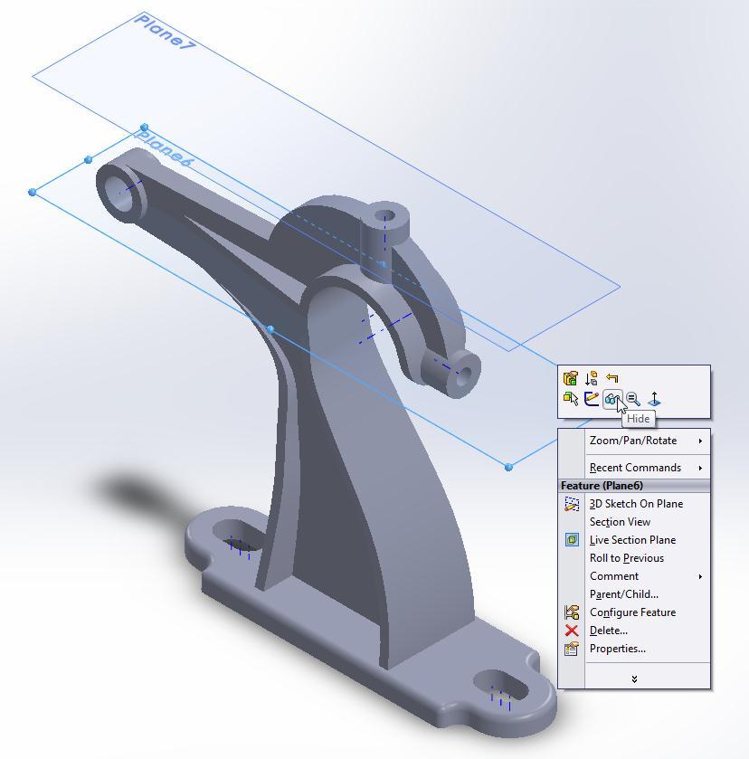
46 Click to exit the sketch mode. Select Features tab and click. Select Mid Plane for Direction 1. Enter 0.38 inch for the depth. Click. Create a reference plane at the distance of 5.75 inches from the bottom of the base feature or Top Plane. Hold the CTRL key down. Click and drag the boundary of the Top Plane upward in the graphics area. Set the offset distance of 5.75 inches. 46


47 Click. Right-click Plane6 you just created and select Sketch. 47


 as the end")
48 Set the display to Top view. Sketch the following inclined and short horizontal lines 2 lines altogether. Be sure to dimension the left endpoint of the line to the center axis of left cylinder. Note the coincident constraint points (green) as the end points of the line. Sketch this short horizontal line. Sketch this line. Click to exit the sketch mode. 48


49 Select Rib. Pick the line previously sketched. Click the Both Sides button. Enter 0.38 inch for the rib thickness. Click Parallel to Sketch button for the extrusion direction. Check Flip material side if necessary. 49


50 Click. Click from Features tool. Select Front Plane for Mirror Face/Plane. Select Rib1 as Features to Mirror. 50

51 Click. Click Hole Wizard. The Hole Specification PropertyManager is displayed. 51

52 Select ANSI Inch for Standard. Be sure Hole is selected. Select All Drill Size for Type of the hole. Select 19/32 for Size. Select Through All for End Condition. Click the Position tab. 52


53 Click 3D Sketch. Click on the face of revolved feature as shown. When point tool is active, wherever you pick, a sketch point will be created. Right-click the graphics area and pick Select. Hold the CTRL key down. Pick the center of the hole and pick the nearby axis. 53

54 Select Coincident. Click twice. Pick the Plane6 and hold the CTRL key down. Click and drag the boundary of the Plane6 upward in the graphics area. Set the offset distance of 2.16 inches. 54

55 Click. Right-click Plane7 you just created and select Sketch. 55


56 Set the display to Top view. Draw a circle centered at the origin. The diameter of the circle is 0.76 inch. Click to exit the sketch mode. Select Features tab and click. 56

57 Select Up To Surface for Direction 1. Pick the surface as illustrated below show in pink color. Click. Click Hole Wizard. The Hole Specification PropertyManager is displayed. 57

58 Select ANSI Inch for Standard. Be sure Hole is selected. Select Tap Drills for Type of the hole. Select 3/8-16 for Size. Select Blind for End Condition. Enter 0.75 inch for the depth. Click the Position tab. 58


59 Click 3D Sketch. Click on the face of cylindrical feature as shown. The exact location is not important. When point tool is active, wherever you pick, a sketch point will be created. Right-click the graphics area and pick Select. Pick the center of the hole and hold CTRL-key and pick the nearby axis. 59

60 Select Coincident. Click twice. Select Plane6 and Plane7 and right click the graphics area select Hide. 60
61 61


62 Turn off the visibility of View Temporary Axes. Pick Front Plane from FeatureManager design tree, right click it in the graphics area and select select Sketch. Set the display to Front view. For clarity, set the display to Hidden Lines Visible view. Draw and dimension a vertical centerline as illustrated and then sketch the following triangular section. Note the constraints (Coincident, Tangent and Vertical) indicated by green. Triangular section. 62

63 Click and click to exit the sketch mode. Select Features tab and click Extruded Cut. Pick the section. Select Through All for Direction 1. Select Through All for Direction 2. Click. The front face as indicated by blue color is perfect. 63


64 But there is excess material on the rear flat face (blue color). This area of excess material must be clean up using Extruded Cut. 64


65 Right click the face and select Sketch. Pick Back view. Sketch the following section. Note that the size of the section must cover the area of excess material that has to be removed dimensions are not important. Make sure the arc of the section and outer edge of the small cylinder are coincident. 65


66 Click and click to exit the sketch mode. Select Features tab and click Extruded Cut. Select Through All for Direction 1. Click Reverse Direction button. 66


67 Click. The excess material has been removed. If your Temporary Axes is off, turn it on. Pick Front Plane from FeatureManager design tree, right click it in the graphics area and select select Sketch. Set the display to Front view. 67


68 Draw a horizontal centerline as shown. The left endpoint of the centerline is coincident to the edge of the arc. Centerline. The centerline is aligned with the center of the existing arc. Sketch the following section to be revolved. Click selecting to add rounds of 0.12 inch radius on your own. You might want to use FilletXpert by tab. The resulted Shaft Support model is shown below. 68

69 Click to exit the sketch mode. Select Features tab and click. 69


70 Click. Turn off View Temporary Axes. Click and create 0.26 inch fillets at locations below. 70


71 The last step is to create fillets and rounds with 0.12 inch radius on your own. You might want to change the radius of the fillets e.g inch especially in thinner area if failure occurs. Hint: Use FilletXpert to manage, organize, and reorder constant radius fillets for you. In addition to pick edges, you might want to pick face to be filleted. The FilletXpert automatically calls the FeatureXpert when it has trouble placing a fillet on the specified geometry. The resulted Shaft Hanger model is shown below. 71
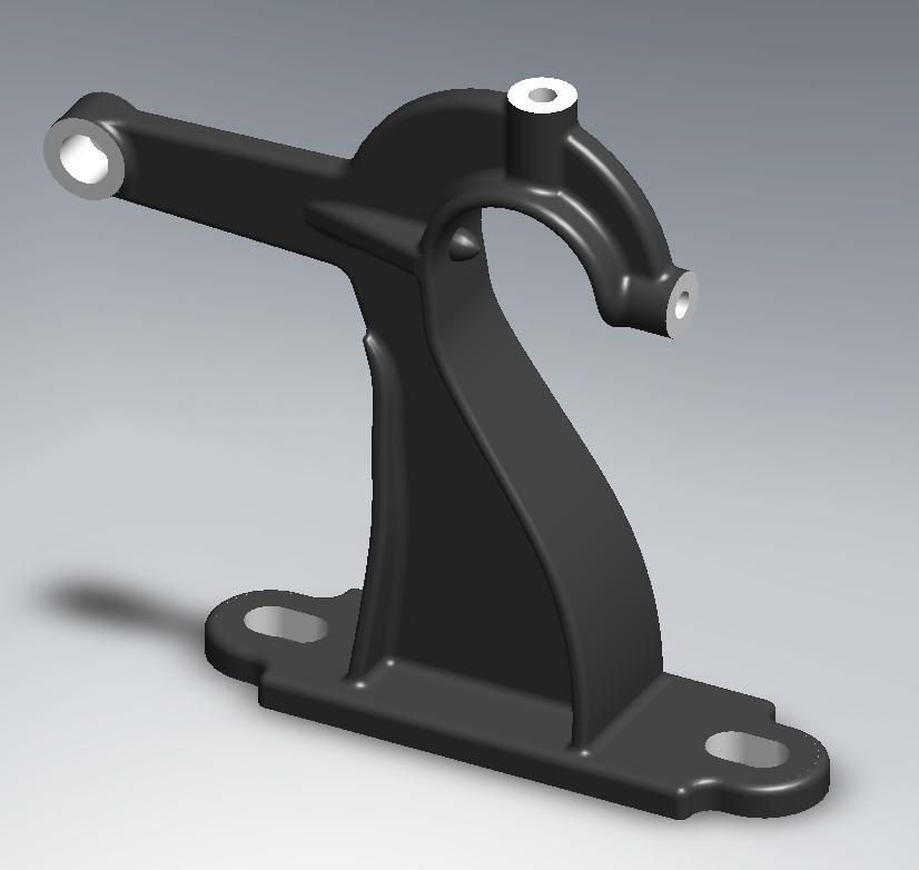
72 72
SolidWorks Part I - Basic Tools SDC. Includes. Parts, Assemblies and Drawings. Paul Tran CSWE, CSWI
 SolidWorks 2015 Part I - Basic Tools Includes CSWA Preparation Material Parts, Assemblies and Drawings Paul Tran CSWE, CSWI SDC PUBLICATIONS Better Textbooks. Lower Prices. www.sdcpublications.com Powered
Beginner s Guide to SolidWorks Alejandro Reyes, MSME Certified SolidWorks Professional and Instructor SDC PUBLICATIONS
 Beginner s Guide to SolidWorks 2008 Alejandro Reyes, MSME Certified SolidWorks Professional and Instructor SDC PUBLICATIONS Schroff Development Corporation www.schroff.com www.schroff-europe.com Part Modeling
Lesson 10: Loft Features
 10 Goals of This Lesson Your students will be able to create the following part: profiles chisel This lesson plan corresponds to the Loft Features chapter of SolidWorks Getting Started. SolidWorks Student
Engineering Design. with SolidWorks A Step-by-Step Project Based Approach Utilizing 3D Solid Modeling
 INSIDE: MultiMedia CD An audio/visual presentation of the tutorial projects Engineering Design with SolidWorks 2010 A Step-by-Step Project Based Approach Utilizing 3D Solid Modeling Introductory Level
Introduction to Revolve - A Glass
 Introduction to Revolve - A Glass Design & Communication Graphics 1 Object Analysis sheet Design & Communication Graphics 2 Prerequisite Knowledge Previous knowledge of the following commands are required
Digital Camera Exercise
 Commands Used New Part This lesson includes Sketching, Extruded Boss/Base, Extruded Cut, Fillet, Chamfer and Text. Click File, New on the standard toolbar. Select Part from the New SolidWorks Document
Engineering & Computer Graphics Workbook Using SOLIDWORKS
 Engineering & Computer Graphics Workbook Using SOLIDWORKS 2017 Ronald E. Barr Thomas J. Krueger Davor Juricic SDC PUBLICATIONS Better Textbooks. Lower Prices. www.sdcpublications.com Powered by TCPDF (www.tcpdf.org)
Engineering & Computer Graphics Workbook Using SolidWorks 2014
 Engineering & Computer Graphics Workbook Using SolidWorks 2014 Ronald E. Barr Thomas J. Krueger Davor Juricic SDC PUBLICATIONS Better Textbooks. Lower Prices. www.sdcpublications.com Powered by TCPDF (www.tcpdf.org)
Below are the desired outcomes and usage competencies based on the completion of Project 4.
 Engineering Design with SolidWorks Project 4 Below are the desired outcomes and usage competencies based on the completion of Project 4. Project Desired Outcomes: An understanding of the customer s requirements
SolidWorks 95 User s Guide
 SolidWorks 95 User s Guide Disclaimer: The following User Guide was extracted from SolidWorks 95 Help files and was not originally distributed in this format. All content 1995, SolidWorks Corporation Contents
Hydro Hull. Chapter 21. Boat. A. Save as "HYDRO". Step 1. Open your HULL MID PLANE file (Chapter 2).
.") Chapter 21 Boat Hydro Hull A. Save as "HYDRO". Step 1. Open your HULL MID PLANE file (Chapter 2). Step 2. Click File Menu > Save As. Step 3. Key-in HYDRO for the filename and press ENTER. B. Delete Loft1,
Chapter 21 Boat Hydro Hull A. Save as "HYDRO". Step 1. Open your HULL MID PLANE file (Chapter 2). Step 2. Click File Menu > Save As. Step 3. Key-in HYDRO for the filename and press ENTER. B. Delete Loft1,
1. Open the Feature Modeling demo part file on the EEIC website. Ask student about which constraints needed to Fully Define.
 BLUE boxed notes are intended as aids to the lecturer RED boxed notes are comments that the lecturer could make Control + Click HERE to view enlarged IMAGE and Construction Strategy he following set of
Engineering Technology
 Engineering Technology Introduction to Parametric Modelling Engineering Technology 1 See Saw Exercise Part 1 Base Commands used New Part This lesson includes Sketching, Extruded Boss/Base, Hole Wizard,
Toothbrush Holder. A drawing of the sheet metal part will also be created.
 Prerequisite Knowledge Previous knowledge of the following commands is required to complete this lesson; Sketch (Line, Centerline, Circle, Add Relations, Smart Dimension,), Extrude Boss/Base, and Edit
SolidWorks Navigation
 SolidWorks Basics SolidWorks Navigation Command Bar Feature Tree Model Window Simple Box Select the Front plane Create a new sketch Create a Center Rectangle from the origin Smart Dimension the length
Lesson 4 Holes and Rounds
 Lesson 4 Holes and Rounds 111 Figure 4.1 Breaker OBJECTIVES Sketch arcs in sections Create a straight hole through a part Complete a Sketched hole Understand the Hole Tool Use Info to extract information
Foreword. If you have any questions about these tutorials, drop your mail to
 Foreword The main objective of these tutorials is to give you a kick start using Solidworks. The approach to write this tutorial is based on what is the most important knowledge you should know and what
From the above fig. After sketching the path and profile select the sweep command First select the profile from property manager tree And then select
 Chapter 5 In sweep command there is a) Two sketch profiles b) Two path c) One sketch profile and one path The sweep profile is used to create threads springs circular things and difficult geometry. For
SDC. SolidWorks Tutorial 2001Plus. A Competency Project Based Approach Utilizing 3D Solid Modeling. David C. Planchard & Marie P.
 2001Plus A Competency Project Based Approach Utilizing 3D Solid Modeling David C. Planchard & Marie P. Planchard SDC PUBLICATIONS www.schroff.com www.schroff-europe.com Project 2 Below are the desired
Assembly Receiver/Hitch/Ball/Pin to use for CAD LAB 5A and 5B:
 MECH 130 CAD LAB 5 SPRING 2017 due Friday, April 21, 2016 at 4:30 PM All of LAB 5 s hardcopies will be working drawing layouts. Do not print out from the part file. We will be using the ME130DRAW drawing
Chair. Bottom Rail. on the Command Manager. on the Weldments toolbar.
 Chapter 2 Chair Bottom Rail A. Weldments Toolbar. Step 1. Click File Menu > New, click Part and OK. Step 2. Right click Sketch on the Command Manager toolbar and select Weldments, Fig. 1. Step 3. Click
Engineering Design with SolidWorks A Step-by-Step Project Based Approach Utilizing 3D Solid Modeling. David C. Planchard & Marie P.
 Engineering Design with SolidWorks 2003 A Step-by-Step Project Based Approach Utilizing 3D Solid Modeling David C. Planchard & Marie P. Planchard SDC PUBLICATIONS www.schroff.com www.schroff-europe.com
AEROPLANE. Create a New Folder in your chosen location called Aeroplane. The four parts that make up the project will be saved here.
 AEROPLANE Prerequisite Knowledge Previous knowledge of the following commands is required to complete this lesson. Sketching (Line, Rectangle, Arc, Add Relations, Dimensioning), Extrude, Assemblies and
SolidWorks 2005 Tutorial. and MultiMedia CD. A Step-by-step Project Based Approach Utilizing 3D Solid Modeling
 INSIDE: MultiMedia CD An audio/visual presentation of the tutorial projects SolidWorks 2005 Tutorial and MultiMedia CD A Step-by-step Project Based Approach Utilizing 3D Solid Modeling David C. Planchard
Introduction to Sheet Metal Features SolidWorks 2009
 SolidWorks 2009 Table of Contents Introduction to Sheet Metal Features Base Flange Method Magazine File.. 3 Envelopment & Development of Surfaces.. 14 Development of Transition Pieces.. 23 Conversion to
Solid Part Four A Bracket Made by Mirroring
 C h a p t e r 5 Solid Part Four A Bracket Made by Mirroring This chapter will cover the following to World Class standards: Sketch of a Solid Problem Draw a Series of Lines Finish the 2D Sketch Extrude
10/14/2010. Chevy Malibu. Vehicle Design with Solidworks. Start SolidWorks Create a New SolidWorks Document. Miles, Rowardo B
 Chevy Malibu Vehicle Design with Solidworks Start SolidWorks Create a New SolidWorks Document Miles, Rowardo B 1 Click: Part and then OK Now you are ready to make a Part. 2 Right Toolbar: Document Properties:
DEPARTMENT OF MECHANICAL AND INDUSTRIAL ENGINEERING NORTHEASTERN UNIVERSITY
 DEPARTMENT OF MECHANICAL AND INDUSTRIAL ENGINEERING NORTHEASTERN UNIVERSITY CAPSULE PROGRAM Funded by NSF grant #0833636 Tutorial 02 3D Part Modeling SolidWorks 2010 Copyright 2010 Prof. Zeid 3D Part Modeling
Advance Dimensioning and Base Feature Options
 Chapter 4 Advance Dimensioning and Base Feature Options Learning Objectives After completing this chapter you will be able to: Dimension the sketch using the autodimension sketch tool. Dimension the sketch
Introduction to Circular Pattern Flower Pot
 Prerequisite Knowledge Previous knowledge of the sketching commands Line, Circle, Add Relations, Smart Dimension is required to complete this lesson. Previous examples of Revolved Boss/Base, Cut Extrude,
Bottom Rail. Chapter 2. Chair. A. Weldments Toolbar. Step 1. Click File Menu > New, click Part and OK. B. 3D Sketch.
 Chapter 2 Chair Bottom Rail A. Weldments Toolbar. Step 1. Click File Menu > New, click Part and OK. Step 2. Right click Sketch on the Command Manager toolbar and select Weldments, Fig. 1. Step 3. Click
Veerapandian.K Mechanical Engg Vedharanyam A manual to mechanical designers How Solid works Works?
 Compiled by Veerapandian.K Mechanical Engg Vedharanyam-614 810 A manual to mechanical designers How Solid works Works? Solid works Overview Solid works main idea is user to create drawing directly in 3D
Siemens NX11 tutorials. The angled part
 Siemens NX11 tutorials The angled part Adaptation to NX 11 from notes from a seminar Drive-to-trial organized by IBM and GDTech. This tutorial will help you design the mechanical presented in the figure
Feature-Based Modeling and Optional Advanced Modeling. ENGR 1182 SolidWorks 05
 Feature-Based Modeling and Optional Advanced Modeling ENGR 1182 SolidWorks 05 Today s Objectives Feature-Based Modeling (comprised of 2 sections as shown below) 1. Breaking it down into features Creating
Introducing SolidWorks
 Introducing SolidWorks SAAST Robotics 2008 SolidWorks Software Visually-based 3-D Mechanical design software Engineers and Designers use it to: Quickly sketch out ideas Experiment with features, dimensions
< Then click on this icon on the vertical tool bar that pops up on the left side.
 Pipe Cavity Tutorial Introduction The CADMAX Solid Master Tutorial is a great way to learn about the benefits of feature-based parametric solid modeling with CADMAX. We have assembled several typical parts
Starting a 3D Modeling Part File
 1 How to Create a 3D Model and Corresponding 2D Drawing with Dimensions, GDT (Geometric Dimensioning and Tolerance) Symbols and Title Block in SolidWorks 2013-2014 By Edward Locke This tutorial will introduce
Alternatively, the solid section can be made with open line sketch and adding thickness by Thicken Sketch.
 Sketcher All feature creation begins with two-dimensional drawing in the sketcher and then adding the third dimension in some way. The sketcher has many menus to help create various types of sketches.
Introduction to 3D CAD with SolidWorks. Jianan Li
 Introduction to 3D CAD with SolidWorks Jianan Li Create a New Part The first time you launch SolidWorks, it asks you to set the default units and dimension standard. Make sure you have IPS and ANSI selected,
How to Build a Game Console. David Hunt, PE
 How to Build a Game Console David Hunt, PE davidhunt@outdrs.net Covering: Drafts Fillets Shells Patterns o Linear o Circular Using made-for-the-purpose sketches to define reference geometry Using reference
DUE DATE: Friday 4/6/2018 at 3:30 PM
 MECH 130 SPRING 2018 CAD LAB 4 FINAL REVISION HARDCOPIES NEEDED DUE DATE: Friday 4/6/2018 at 3:30 PM After the revised hitch, the ball and the pin parts were created from the Handout call LAB4 PART Creation,
Introduction to CATIA V5
 Introduction to CATIA V5 Release 17 (A Hands-On Tutorial Approach) Kirstie Plantenberg University of Detroit Mercy SDC PUBLICATIONS Schroff Development Corporation www.schroff.com Better Textbooks. Lower
SolidWorks Design & Technology
 SolidWorks Design & Technology Training Course at PHSG Ex 5. Lego man Working with part files 8mm At first glance the Lego man looks complicated but I hope you will see that if you approach a project one
Datum Tutorial Part: Cutter
 Datum Tutorial Part: Cutter Objective: Learn to apply Datums in different ways Directions 1. Datum Axis Creation a. First we need to create a center axis for the cutter b. Model Tab > Datum > Select Axis
Clock Exercise (Inserting Planes)
") Clock Exercise (Inserting Planes) Prerequisite Knowledge To complete this exercise you will need to be familiar with Sketching, Applying relations, Extrude Boss/ Base, Extrude cut, Applying Textures, Renaming
Clock Exercise (Inserting Planes) Prerequisite Knowledge To complete this exercise you will need to be familiar with Sketching, Applying relations, Extrude Boss/ Base, Extrude cut, Applying Textures, Renaming
SolidWize. Online SolidWorks Training. Simple Sweep: Head Scratcher
 SolidWize Online SolidWorks Training Simple Sweep: Head Scratcher Step 1: Creating the Handle: Sketch Using Inches as the unit create a sketch on the Front plane. Start with the sketch shown below: Create
Basic Features. In this lesson you will learn how to create basic CATIA features. Lesson Contents: CATIA V5 Fundamentals- Lesson 3: Basic Features
 Basic Features In this lesson you will learn how to create basic CATIA features. Lesson Contents: Case Study: Basic Features Design Intent Stages in the Process Determine a Suitable Base Feature Create
Module 1H: Creating an Ellipse-Based Cylindrical Sheet-metal Lateral Piece
 Inventor (10) Module 1H: 1H- 1 Module 1H: Creating an Ellipse-Based Cylindrical Sheet-metal Lateral Piece In this Module, we will learn how to create an ellipse-based cylindrical sheetmetal lateral piece
Module 2.1, 2.2 Review. EF101 Analysis & Skills Module 2.3. Sketched Features and Operations. On-line Help Two Locations
 EF101 Analysis & Skills Module 2.3 Engineering Graphics Revolved Features Placed Features Work Features Module 2.1, 2.2 Review What are the three types of operations for adding features to the base feature?
SolidWorks Training. Introductory course for staff and students from the School of Physics and Astronomy
 SolidWorks Training Introductory course for staff and students from the School of Physics and Astronomy i) Introductory presentation SolidWorks Training ii) The SolidWorks GUI The SolidWorks Graphical
EN1740 Computer Aided Visualization and Design Spring 2012
 EN1740 Computer Aided Visualization and Design Spring 2012 1/31/2012 Brian C. P. Burke PLEASE WAIT TO LAUNCH PRO/E IF ALREADY OPENED, PLEASE CLOSE PLEASE WAIT TO LAUNCH PRO/E PLEASE CLOSE IF ALREADY OPENED
for Solidworks TRAINING GUIDE LESSON-9-CAD
 for Solidworks TRAINING GUIDE LESSON-9-CAD Mastercam for SolidWorks Training Guide Objectives You will create the geometry for SolidWorks-Lesson-9 using SolidWorks 3D CAD software. You will be working
Module 1G: Creating a Circle-Based Cylindrical Sheet-metal Lateral Piece with an Overlaying Lateral Edge Seam And Dove-Tail Seams on the Top Edge
 Inventor (10) Module 1G: 1G- 1 Module 1G: Creating a Circle-Based Cylindrical Sheet-metal Lateral Piece with an Overlaying Lateral Edge Seam And Dove-Tail Seams on the Top Edge In Module 1A, we have explored
SOLIDWORKS 2016 Advanced Techniques
 SOLIDWORKS 2016 Advanced Techniques Mastering Parts, Surfaces, Sheet Metal, SimulationXpress, Top Down Assemblies, Core & Cavity Molds Paul Tran CSWE, CSWI SDC PUBLICATIONS Better Textbooks. Lower Prices.
Solidworks: Lesson 4 Assembly Basics and Toolbox. UCF Engineering
 Solidworks: Lesson 4 Assembly Basics and Toolbox UCF Engineering Solidworks We have now completed the basic features of part modeling and it is now time to begin constructing more complex models in the
Lesson 4 Extrusions OBJECTIVES. Extrusions
 Lesson 4 Extrusions Figure 4.1 Clamp OBJECTIVES Create a feature using an Extruded protrusion Understand Setup and Environment settings Define and set a Material type Create and use Datum features Sketch
Rotational Patterns of Sketched Features Using Datum Planes On-The-Fly
 Rotational Patterns of Sketched Features Using Datum Planes On-The-Fly Patterning a sketched feature (such as a slot, rib, square, etc.,) requires a slightly different technique. Why can t we create a
SolidWorks Reference Geometry
 SolidWorks Reference Geometry IDeATe Laser Micro Part 2 Dave Touretzky and Susan Finger 1. Symmetry and Reference Geometry Today, you ll make this part bear-like face and then cut it on the laser cutter:
Lab 3 Introduction to SolidWorks I Silas Bernardoni 10/9/2008
 1 Introduction This lab is designed to provide you with basic skills when using the 3D modeling program SolidWorks. You will learn how to build parts, assemblies and drawings. You will be given a physical
Modeling an Airframe Tutorial
 EAA SOLIDWORKS University p 1/11 Difficulty: Intermediate Time: 1 hour As an Intermediate Tutorial, it is assumed that you have completed the Quick Start Tutorial and know how to sketch in 2D and 3D. If
ME Week 2 Project 2 Flange Manifold Part
 1 Project 2 - Flange Manifold Part 1.1 Instructions This project focuses on additional sketching methods and sketching commands. Revolve and Work features are also introduced. The part being modeled is
Computer Aided Design Module 2. Lesson Toblerone Bar
 Computer Aided Design Module 2 Lesson Toblerone Bar Lesson? Toblerone Bar New Commands used: Polygon, Add Relations, Smart Dimension, Extrude Boss/Base (Mid Plane), Fillet, Line, Extrude-Cut, Linear Pattern
Table of Contents. Lesson 1 Getting Started
 NX Lesson 1 Getting Started Pre-reqs/Technical Skills Basic computer use Expectations Read lesson material Implement steps in software while reading through lesson material Complete quiz on Blackboard
Part Design Fundamentals
 Part Design Fundamentals 1 Course Presentation Objectives of the course In this course you will learn basic methods to create and modify solids features and parts Targeted audience New CATIA V5 Users 1
Evaluation Chapter by CADArtifex
 The premium provider of learning products and solutions www.cadartifex.com EVALUATION CHAPTER 2 Drawing Sketches with SOLIDWORKS In this chapter: Invoking the Part Modeling Environment Invoking the Sketching
Lesson 6 2D Sketch Panel Tools
 Lesson 6 2D Sketch Panel Tools Inventor s Sketch Tool Bar contains tools for creating the basic geometry to create features and parts. On the surface, the Geometry tools look fairly standard: line, circle,
Part 8: The Front Cover
 Part 8: The Front Cover 4 Earpiece cuts and housing Lens cut and housing Microphone cut and housing The front cover is similar to the back cover in that it is a shelled protrusion with screw posts extruding
Module 2: Radial-Line Sheet-Metal 3D Modeling and 2D Pattern Development: Right Cone (Regular, Frustum, and Truncated)
") Inventor (5) Module 2: 2-1 Module 2: Radial-Line Sheet-Metal 3D Modeling and 2D Pattern Development: Right Cone (Regular, Frustum, and Truncated) In this tutorial, we will learn how to build a 3D model
Inventor (5) Module 2: 2-1 Module 2: Radial-Line Sheet-Metal 3D Modeling and 2D Pattern Development: Right Cone (Regular, Frustum, and Truncated) In this tutorial, we will learn how to build a 3D model
Introduction to Autodesk Inventor for F1 in Schools (Australian Version)
") Introduction to Autodesk Inventor for F1 in Schools (Australian Version) F1 in Schools race car In this course you will be introduced to Autodesk Inventor, which is the centerpiece of Autodesk s Digital
Introduction to Autodesk Inventor for F1 in Schools (Australian Version) F1 in Schools race car In this course you will be introduced to Autodesk Inventor, which is the centerpiece of Autodesk s Digital
Working With Drawing Views-I
 Chapter 12 Working With Drawing Views-I Learning Objectives After completing this chapter you will be able to: Generate standard three views. Generate Named Views. Generate Relative Views. Generate Predefined
Wireless Mouse Surfaces
 Wireless Mouse Surfaces Design & Communication Graphics Table of Contents Table of Contents... 1 Introduction 2 Mouse Body. 3 Edge Cut.12 Centre Cut....14 Wheel Opening.. 15 Wheel Location.. 16 Laser..
Creo Revolve Tutorial
 Creo Revolve Tutorial Setup 1. Open Creo Parametric Note: Refer back to the Creo Extrude Tutorial for references and screen shots of the Creo layout 2. Set Working Directory a. From the Model Tree navigate
Using Siemens NX 11 Software. The connecting rod
 Using Siemens NX 11 Software The connecting rod Based on a Catia tutorial written by Loïc Stefanski. At the end of this manual, you should obtain the following part: 1 Introduction. Start NX 11 and open
Module 1C: Adding Dovetail Seams to Curved Edges on A Flat Sheet-Metal Piece
 1 Module 1C: Adding Dovetail Seams to Curved Edges on A Flat Sheet-Metal Piece In this Module, we will explore the method of adding dovetail seams to curved edges such as the circumferential edge of a
Copyrighted. Material. Copyrighted. Material. Copyrighted. Material. Copyrighted. Material
 ENGINEERING & COMPUTER GRAPHICS WORKBOOK Using SolidWorks 2005 Ronald E. Barr Thomas J. Krueger Theodore A. Aanstoos Davor Juricic SDC PUBLICATIONS Schroff Development Corporation www.schroff.com www.schroff-europe.com
Advanced Modeling Techniques Sweep and Helical Sweep
 Advanced Modeling Techniques Sweep and Helical Sweep Sweep A sweep is a profile that follows a path placed on a datum. It is important when creating a sweep that the designer plans the size of the path
Tech-World Manufacturing. Design. Level two. CELL Guide. Edition E0
 Tech-World Manufacturing Design Level two Edition 5 37186-E0 FIFTH EDITION First Printing, February 2011 Copyright 2005, 2006, 2007, 2008, 2009, 2010, 2011 Lab-Volt Systems, Inc. All rights reserved.
Introduction to Autodesk Inventor User Interface Student Manual MODEL WINDOW
 Emmett Wemp EDTECH 503 Introduction to Autodesk Inventor User Interface Fill in the blanks of the different tools available in the user interface of Autodesk Inventor as your instructor discusses them.
Modeling Basic Mechanical Components #1 Tie-Wrap Clip
 Modeling Basic Mechanical Components #1 Tie-Wrap Clip This tutorial is about modeling simple and basic mechanical components with 3D Mechanical CAD programs, specifically one called Alibre Xpress, a freely
When you complete this assignment you will:
 Objjectiives When you complete this assignment you will: 1. sketch and create models using new work planes and the loft command. 2. sketch and create models using the revolve command. 3. sketch and dimension
g. Click once on the left vertical line of the rectangle.
 This drawing will require you to a model of a truck as a Solidworks Part. Please be sure to read the directions carefully before constructing the truck in Solidworks. Before submitting you will be required
Product Modelling in Solid Works
 Product Modelling in Solid Works In the following exercise you will use solid works to construct the computer mouse shown opposite. In this exercise you will use a number of advanced features to achieve
Module 1E: Parallel-Line Flat Pattern Development of Sheet- Metal Folded Model Wrapping the 3D Space of An Oblique Circular Cylinder
 Inventor (10) Module 1E: 1E- 1 Module 1E: Parallel-Line Flat Pattern Development of Sheet- Metal Folded Model Wrapping the 3D Space of An Oblique Circular Cylinder In this Module, we will explore the topic
1. Create a 2D sketch 2. Create geometry in a sketch 3. Use constraints to position geometry 4. Use dimensions to set the size of geometry
 2.1: Sketching Many features that you create in Fusion 360 start with a 2D sketch. In order to create intelligent and predictable designs, a good understanding of how to create sketches and how to apply
Van Assembly. Creating an Assembly. Original by Steven Jaffe Modified by E. Brunelle 2/07 1
 Van Assembly Creating an Assembly 1 Part One the Axle 1. Set Units to Inches 2. Create a New Design. 3. Save the Design as axleinl_cad1_1 in your Van folder. 4. Create a New Sketch on the Lateral workplane.
Training Guide Basics
 Training Guide Basics 2014, Missler Software. 7, Rue du Bois Sauvage F-91055 Evry, FRANCE Web: www.topsolid.com E-mail: info@topsolid.com All rights reserved. TopSolid Design Basics This information is
IT, Sligo. Equations Tutorial
 Equations Tutorial Parametric Modelling: SolidWorks is a parametric modelling system where parameters, such as dimensions and relations, are used to create and control the geometry of the modelled part.
SolidWize. Online SolidWorks Training. Lofts: Tea Pot
 SolidWize Online SolidWorks Training Lofts: Tea Pot Step 1: Creating the Body Using inches as the unit, create the following sketch on the top plane. We will now add a plane above the top plane so that
Purlin Roof. Create a New Folder in your chosen location called Purlin Roof. The nine parts that make up the project will be saved here.
 Purlin Roof Prerequisite Knowledge Previous knowledge of the following commands is required to complete this lesson. Sketching (Line, Rectangle, Add Relations, Dimensioning), Inserting Planes, Extrude,
Sash Clamp. Sash Clamp SW 2015 Design & Communication Graphics Page 1.
 Sash Clamp 1 Introduction: The Sash clamp consists of nine parts. In creating the clamp we will be looking at the improvements made by SolidWorks in linear patterns, adding threads and in assembling the
Quick Start for Autodesk Inventor
 Quick Start for Autodesk Inventor Autodesk Inventor Professional is a 3D mechanical design tool with powerful solid modeling capabilities and an intuitive interface. In this lesson, you use a typical workflow
Activity 5.5a CAD Model Features Part 1
 Activity 5.5a CAD Model Features Part 1 Introduction In order to use CAD effectively as a design tool, the designer must have the skills necessary to create, edit, and manipulate a 3D model of a part in
Student + Instructor:
 BLUE boxed notes are intended as aids to the lecturer RED boxed notes are comments that the lecturer could make Show 01 Solid Modeling Intro slides quickly. SolidWorks Layout slides are on EEIC for reference
Copyrighted. Material. Copyrighted. Material. Copyrighted. Material. Copyrighted. Material
 ENGINEERING & COMPUTER GRAPHICS WORKBOOK Using SolidWorks 2008 Ronald E. Barr Thomas J. Krueger Theodore A. Aanstoos Davor Juricic SDC PUBLICATIONS Schroff Development Corporation www.schroff.com Better
Made Easy. Jason Pancoast Engineering Manager
 3D Sketching Made Easy Jason Pancoast Engineering Manager Today I have taught you to sketch in 3D. It s as easy as counting ONE, TWO, FIVE...er...THREE! When your sketch only lives in Y and in X, Adding
Custom Pillow Block Design Protrusion, Cut, Round, Draft (Review) Drawing (Review) Inheritance Feature (New) Creo 2.0
 Drawing (Review) Inheritance Feature (New) Creo 2.0") Custom Pillow Block Design Protrusion, Cut, Round, Draft (Review) Drawing (Review) Inheritance Feature (New) Creo 2.0 Rotatable pdf files: Casting Machining Grease Fitting Boss The general design of the
Custom Pillow Block Design Protrusion, Cut, Round, Draft (Review) Drawing (Review) Inheritance Feature (New) Creo 2.0 Rotatable pdf files: Casting Machining Grease Fitting Boss The general design of the
Chapter 2. Drawing Sketches for Solid Models. Learning Objectives
 Chapter 2 Drawing Sketches for Solid Models Learning Objectives After completing this chapter, you will be able to: Start a new template file to draw sketches. Set up the sketching environment. Use various
Spatula. Spatula SW 2015 Design & Communication Graphics Page 1
 Spatula Introduction: The model shown in the picture is made of three parts, - the base, the washer and the handle. The base requires the use of Spline and Style Spline command, Slot command and Mirror