Part Design Fundamentals
|
|
|
- Teresa McDaniel
- 5 years ago
- Views:
Transcription

1 Part Design Fundamentals 1
2 Course Presentation Objectives of the course In this course you will learn basic methods to create and modify solids features and parts Targeted audience New CATIA V5 Users 1 day Prerequisites CATIA Basics 2
3 Table of Contents (1/2) 1. Introduction to CATIA V5 p.5 Part Design Workbench Presentation p.6 2. Sketch-Based Features p.13 Creating Pads p.14 Pad: Reverse Side p.23 Creating Pockets p.29 Creating Thin Solids p.39 Creating Shafts p.43 Limiting Features p.55 Creating Holes p Dressing-Up Features p.77 Creating Drafts p.78 Variable Draft Angle p.89 Filleting p.96 Edge Fillet with Limiting Planes, Faces or Surfaces p.103 3
4 Table of Contents (2/2) Edge Fillet: Trim Ribbon p.106 Face-Face Fillets p.107 Tri-Tangent Fillets p.109 Variable Radius Fillets p.110 Chamfering p.116 Drafted Filleted Pads/Pockets p.125 Shelling a Part p.132 Creating Patterns p.148 Mirror p Modifying Parts p.160 Modifying Profile Geometry p.161 Reordering Features p.168 Modifying Features p.174 4
5 Introduction to Part Design You will become familiar with the CATIA V5 Part Design main features 5
6 What is Part Design? The Version 5 Part Design application makes it possible to design precise 3D mechanical parts with an intuitive and flexible user interface, from sketching in an assembly context to iterative detailed design. Version 5 Part Design application will enable you to accommodate design requirements for parts of various complexities, from simple to advanced. This new application, which combines the power of feature-based design with the flexibility of a Boolean approach, offers a highly productive and intuitive design environment with multiple design methodologies, such as post-design and local 3D parameterization. As a scalable product, Part Design can be used in cooperation with other current or future companion products such as Assembly Design and Generative Drafting. The widest application portfolio in the industry is also accessible through interoperability with CATIA Solutions Version 4 to enable support of the full product development process from initial concept to product in operation. 6


7 Accessing the Part Design Workbench 1 2 Anywhere from 1- Start menu 2- File / New menu 7

8 Part Design Interface : General Presentation CATPart extension Standard tools Part tree Sketcher access... Features... Part Design tools... 8


9 Part Design Interface Insert menu Constraints Sketch-based See Wireframe and Surfaces Dress-up Transformations Operations 9


.")
 A body is a set of features that can be")
10 Part Design Terminology A Part is a combination of one or more features, and bodies The first feature is generated from a sketch (profile), by extrusion or revolution Features are components based on sketches (sketch-based) or on existing features (dress-up and transformation). They can also be generated from surfaces (surface-based) A body is a set of features that can be assembled to a part through Boolean operations (Assemble, remove,...) 10
 or Create a new part > insert in")


11 Part Design General Process From Assembly > create a new part (Top-down approach) or Create a new part > insert in assembly (Bottom-up approach) 1 Sketch the profile of the main pad 2 Generate the main pad Create additional features 4 Add dress-up features 3 5 Modify & reorder features 6 Insert new features or bodies for more complex parts 11
12 To Sum Up... You have seen CATIA V5 Part Design User interface: How to access the workbench Its user interface and tools The terminology that will be used The general design process... and Basic functions: Extruding features (pads, pockets) Adding fillets, drafts Mirroring and shelling the part 12
13 Sketch Based Features You will learn how to create and limit the most frequently used sketch-based features such as pads Creating Pads Creating Pockets Creating Thin Solids Creating Shafts Limiting Features Creating Holes To Sum Up 13

")
14 Creating Pads You will learn how to create simple pads from a 2D profile (or sketch) Extruded Pad 14


 or with respect to other")
15 What is a Pad? A pad is a basic solid which is extruded from a 2D profile, called sketch It is one of the first features that can be created when starting a new part 2D profile (sketch) Extruded pad Length Its length can be defined by dimensions (exact values) or with respect to other 3D elements (thus associative). Length types 15


16 Creating Simple Pads... 1 Select the profile 3 OK to validate 2 Define the pad s dimensions 16


17 Creating a Simple Pad 1 Select the Profile sketch to be used for the Pad 2 Select the Pad icon 3 Modify the Pad definition You get: The Pad definition can be modified after creation by double clicking on the Pad geometry or product structure 17
18 Pad : Selection of a Sub-Part of a Sketch (1/2) When creating a Pad, it is possible to select only certain sub-elements of a sketch as the pad profile 1 Select the Pad icon (be sure that no sketch is selected) 3 If necessary, select the Sub-elements option from the appearing dialog box 2 Using the right mouse button (MB3) on the Profile Selection field, select Go to profile definition 18

19 Pad : Selection of a Sub-Part of a Sketch (2/2) When creating a Pad, it is possible to select only certain sub-elements of a sketch as the pad profile 4 Select one edge of the subelement you want to extrude 5 Select OK 6 Select OK You get: 19


20 Multi-Length Pad (1/3) You can extrude multiple profiles belonging to a same sketch using different length values. The multi-pad capability lets you do this at one time. 1 Select the Multi-length pad icon 3 The Pad Definition dialog box is displayed. You can see the number of domains to be extruded. 2 Select the Sketch. Note that all profiles must be closed and must not intersect. 20


21 Multi-Length Pad (2/3) You can extrude multiple profiles belonging to a same sketch using different length values. The multi-pad capability lets you do this at one time. 4 A red arrow is displayed normal to the sketch. It indicates the proposed extrusion direction. To reverse it, you just need to click it. 5 Select a Domain in the list. This one now appears in blue in the geometry area. 21

22 Multi-Length Pad (3/3) You can extrude multiple profiles belonging to a same sketch using different length values. The multi-pad capability lets you do this at one time. 6 Specify the length by entering a value. For example, enter 20mm. Repeat the operation for each extrusion domain. 7 Click OK to create the Multi-height Pad. Note that you can multi - select extrusion domains in the list before defining a common length or thickness. 22
23 Pad : Reverse Side The Reverse Side button applies to open profiles only. This option lets you choose which side of the profile is to be extruded 1 Select the Pad icon 2 Select the open sketch 3 Modify the Pad length 4 Select the arrow to reverse the pad side (or click the Reverse Side button in the dialog box) 5 Select OK in the dialog box You get: 23


24 Additional Information (1/5) Open profiles CATIA allows you to create pads from open profiles provided existing geometry can trim the pads. Example on the right illustrates this concept. Multiple profiles Pads can also be created from sketches including several profiles. These profiles must not intersect. In this example, the sketch to be extruded is defined by a square and a circle. Applying the Pad command on this sketch lets you obtain a cavity Arc Pad Square & circle Cavity 24


25 Additional Information (2/5) Adding Sub-Elements It is also possible to add other sub-elements during the profile definition Select Add Select the Sub-element to be added 25


26 Additional Information (3/5) Removing Sub-Elements It is also possible to remove other sub-elements during the profile definition Select the Sub-element to be removed Select Remove 26


27 Additional Information (4/5) Solving Ambiguity Capability to solve ambiguity when selecting a sub part of a sketch Select the edge Ambiguity Select the edge to solve the ambiguity You get: 27

28 Additional Information (5/5) If no sketch has been created when activating the Pad icon, you can access the Sketcher by selecting the Sketcher icon in the dialog box. When you have completed the sketch, you can leave the Sketcher then you will return to the Pad creation Select the Sketcher icon in the dialog box then select the sketch plane 28

 Blind Pocket Through")
29 Creating Pockets You will learn how to create simple pockets from a 2D profile (or sketch) Blind Pocket Through Pocket 29
 Pocket Length Its length can")
30 What is a Pocket? A pocket is removing material from an existing feature, by extruding a 2D profile 2D profile (sketch) Pocket Length Its length can be defined by dimensions (exact values) or with respect to other 3D elements (thus associative). Length types 30


31 Creating Simple Pockets... 1 Select the profile 3 OK to validate 2 Define pocket s dimensions 31
32 Creating a Simple Pocket 1 Select the Profile sketch to be used for the Pocket 2 Select the Pocket icon 3 Modify the Pocket definition You get: Pockets can also be created from sketches including several profiles. These profiles must not intersect 32
33 Multi-Length Pocket (1/3) You can extrude multiple profiles belonging to a same sketch using different length values. The multi-pocket capability lets you do this at one time. 1 Select the Multi-length pad icon 2 Select the Sketch. Note that all profiles must be closed and must not intersect. 3 The Pocket Definition dialog box is displayed. You can see the number of domains to be extruded. Note that a red arrow is displayed normal to the sketch. It indicates the proposed extrusion direction. To reverse it, you just need to click it. 33

34 Multi-Length Pocket (2/3) You can extrude multiple profiles belonging to a same sketch using different length values. The multi-pocket capability lets you do this at one time. 4 Select a Domain in the list. This one now appears in blue in the geometry area. 5 Specify the length by entering a value. For example, enter 10mm. Repeat the operation for each extrusion domain. Note that you can multi-select extrusion domain from the list before defining a common length or thickness. 34


35 Multi-Length Pocket (3/3) You can extrude multiple profiles belonging to a same sketch using different length values. The multi-pocket capability lets you do this at one time. 6 Click OK to create the Multi-height Pad. 35


36 Pocket : Reverse Side The Reverse Side button applies to open profiles only. This option lets you choose which side of the profile is to be extruded 1 Select the Pocket icon 2 Select the open sketch 3 Modify the Pocket Depth 4 Select the arrow to reverse the pocket side (or click the Reverse Side button in the dialog box) 5 Select OK in the dialog box You get: 36


37 Additional Information (1/2) Open profiles CATIA allows you to create pockets from open profiles if existing geometry can limit the pockets. The example illustrates this concept. Multiple profiles Pockets can also be created from sketches including several profiles. These profiles must not intersect. In the example, the initial sketch is made of eight profiles. Applying the Pocket command on this sketch lets you create eight pockets Open profile 8 profiles Pocket 8 pockets Can a pocket create material? If your pocket is the first feature of a new body, CATIA creates material. 37


38 Additional Information (2/2) If no sketch has been created when activating the Pocket icon, you can access to the Sketcher by selecting the Sketcher icon in the dialog box. When you have completed the sketch, you can leave the Sketcher then you will return to the Pocket creation Select the Sketcher icon in the dialog box then select the sketch plane 38
39 Creating Thin Solids You will learn how to create a Sketch Based feature known as Thin Solids. 39


40 What are Thin Solids? Thin Solids are features resulting from adding Thickness to both sides of a pad s profile. Profile to extrude This task can also be applied on Pocket. Resulting Thin Pad Profile to extrude Resulting Thin Pocket 40


41 Creating Thin Solids (1/2) 1 Select the Sketch. 2 Select the Pad icon. The Pad Definition Dialog box is displayed. You can now define your Thin Pad using the options available in the Thin Pad Frame. 3 Enter Thickness1 and Thickness2 values after clicking on More in the Dialog box. You can see that Material has been added to both sides of the Profile. 4 To add Material equally to both sides, check Neutral fiber. Thickness1 is then distribued equally. Note that Thickness2 is not available. 41


42 Creating Thin Solids (2/2) 5 Using the Thin Pad option, it is possible to extrude Profiles from Networks. The resulting Features do not depend on the wire creation order in Networks. With Merge Ends Without Merge Ends 42


")
43 Creating Shafts You will learn how to create simple Shafts from a 2D profile (or sketch) Shaft 43
44 What is a Shaft? A shaft is a basic solid obtained from the revolution of a 2D profile around an axis The axis and the profile must be created in the same sketch 2D profile (sketch) Shaft Angular Limits Limits : First angle This angle defines the revolution angle of the profile around the axis, starting from the profile position and orientated in the clockwise direction Limits : Second angle This angle defines the revolution angle of the profile around the axis, starting from the profile position and orientated in the counterclockwise direction 44
45 Creating Simple Shafts... 1 Select the profile 3 OK to validate 2 Define the shaft s angular limits 45


46 Creating a Shaft 1 Select the Profile sketch to be used for the Shaft 2 Select the Shaft icon In order to create a shaft, the sketch must include the rotation axis You get: 3 Modify the Shaft definition By offsetting the rotation axis off of the profile, the resulting part can be hollowed. 46

47 Shaft : 3D Line Axis When creating a shaft, it is possible to use a 3d line or a sketched line not included in the sketch of the profile as the rotation axis Select the Shaft 1 icon 2 Select the profile 3 Select the Axis field in the dialog box 4 Select the 3d line as the rotation axis 5 You can modify the Limits parameters then select OK, you get: 47


48 Shaft Creation: Using a 3D Wireframe as Profile It is possible to select a planar wireframe as the profile when creating a shaft Select the Shaft 1 2 Select the following 3D icon wireframe as the Profile 3 Select the axis selection field 4 Select the following sketch as the axis 5 Select Ok i n the dialog box You get: 48


49 Shaft : Reverse Side The Reverse Side button applies to open profiles only. This option lets you choose which side of the profile is to be extruded 3 Modify the Shaft Angles 2 Select the open sketch Select the Shaft icon 1 4 Select the arrow to reverse the shaft side (or click the Reverse Side button in the dialog box) 5 Select OK in the dialog box You get: 49


50 Additional Information (1/5) Shaft with two angular limits : Axis on a profile edge : Axis outside the profile : Axis cutting the profile : Error Open profile : Open profile and axis outside the profile : Error 50


51 Additional Information (2/5) It is also possible to use a 3D wireframe as profile when creating a groove, a stiffener, a rib, or a slot 51


52 Additional Information (3/5) Like for pad or pocket creation, you can use sub-elements of a sketch to create a shaft 52
 You can create")


53 Additional Information (4/5) You can create Shafts from sketches including several closed profiles. These profiles must not intersect 53

54 Additional Information (5/5) If no sketch has been created when activating the Shaft icon, you can access the Sketcher by selecting the Sketcher icon in the dialog box. When you have completed the sketch, you can leave the Sketcher then you will return to the Shaft creation Select the Sketcher icon in the dialog box then select the sketch plane 54


55 Limiting Features You will learn the different ways to limit features Up-to-last Limit Up-to-next Limit 55


56 Why Different Types of Limits? You can specify dimensions to limit a feature You can also limit features onto existing elements. In this case, associativity will propagate design changes To capture the design intent Using "Up to Last" to extrude a pad maintains the configuration even with the insertion of a new feature (see example below) Up to Last 56


57 Limiting Features... Different types of limit Dimension type: you specify the dimensions (ex: 25 mm) Mirrored Extent: Mirrors the feature about it's profile LIM2. LIM1 Up to Plane Uses a plane or face to limit feature Up to Next Uses the next encountered material to limit feature Up to Last Uses the last encountered material to limit feature Up to Surface Uses a surface to limit feature 57


58 Up to Last Pads/Pockets 1 Select the Profile sketch to be Select used for the Pad 2 Pad icon 3 Modify the Pad definition to include type Up to last You get: The Up to Last type is also used for defining the limits of Pockets 58


59 Up to Surface Pads/Pockets 1 Select the Profile sketch to be used for the Pad 2 Select the Pad icon 3 Modify the Pad definition to include type Up to Surface You get: 4 Select the limit surface on the part The Up to Surface type is also used for defining Pockets limits 59


60 Mirroring a Pad with Mirrored Extent 1 Select the Profile sketch to be used for the Pad 2 Select Pad icon 3 Select Mirrored Extent to mirror the Pad about the profile with the specified limit You get: Using Mirrored Extent instead of the Mirror function streamlines your product structure 60


61 Offset on Pad Limit (1/2) When creating a pad using the Up to surface option as one of the pad limit, it is possible to define a positive or negative offset from the selected surface Activate the Pad 1 icon 2 Select the Profile 3 Select the Up to surface as First Limit Option using the combo 4 Select the face 61


62 Offset on Pad Limit (2/2) When creating a pad using the Up to surface option as one of the pad limit, it is possible to define a positive or negative offset from the selected surface 5 Enter -25 as the Offset You get : 6 Select OK 62
")


63 Additional Information (1/2) Limiting Holes & Pockets Whatever hole you choose, you need to specify the limit you want. There is a variety of limits: Special case When using the Up-to-Next option: Blind / Dimension Up-to-Next Up-to-Last Up-to-Plane / Surface 63

64 Additional Information (2/2) When creating a pad/pocket using the Up to surface option as one of the pad/pocket limits, you can access the following contextual menu in the Offset field: To create or edit a formula between The Offset and another parameter To change the Offset value through a dialog box To add a maximum and minimum tolerance on the Offset parameter To modify the incremental value of the Offset To enter a measure, in order to send the result of the measure into the Offset parameter To define a range : the Offset value cannot go beyond or below To add a comment on the Offset parameter 64


65 Creating Holes You will learn how to create different types of hole and locate them on existing features Blind Hole Countersunk Through Hole... 65


66 What is a Hole? A hole is removing circular material all at once, from an existing feature Its length can be defined by dimensions or with respect to other 3D elements Rough or Precise Location? Approximate location Concentric Hole The hole can be roughly or precisely located. You can locate precisely a hole at creation or after Sketch or not? Note that you do not need a sketch to create a hole. The sketch of the hole is automatically created. To locate precisely a hole after creation, you edit its sketch and constrain its center point for example You will use Hole instead of Pocket because you can create holes including technological information such as thread, angle bottom, counter bore... 66


67 Creating and Locating Holes... To create a hole you need to define its position then its dimensions 3 OK to validate 1 Place the hole 2 Define hole s dimensions 67


68 Creating and Positioning a Hole 1 Multi-select 2 edges as position reference 2 Select the Hole icon 3 Select the face the hole will start on 4 Modify the hole definition 5 Modify the distance to edges You get: Since holes are sketch based you can also position them after they have been created by editing the sketch 68
69 Offset on Hole (1/2) When creating a hole using one of the Up to options, it is possible to define an offset in accordance with this limit. The offset can be positive or negative 1 Select the Hole icon 3 Activate the Up to plane option and enter 30 as the hole diameter 2 Select the face on which the hole will be placed 69


 6 Enter -10 as the Offset 7 Select OK")
70 Offset on Hole (2/2) When creating a hole using one of the Up to options, it is possible to define an offset in accordance with this limit. The offset can be positive or negative Select the Limit 4 field 5 Select the Select the limiting plane (face) 6 Enter -10 as the Offset 7 Select OK You get: 10 70


71 Standard Thread Definition (1/2) Access to standard thread design tables when creating a threaded hole Select the Hole icon 1 2 Select the face on which the hole will be placed 3 Select the V-Bottom option from the Bottom combo 4 Select the Tread Definition tab 5 Select the Threaded button 6 Select the Metric Thick Pitch type of thread 71


")
72 Standard Thread Definition (2/2) Access to standard thread design tables when creating a threaded hole 7 Select M20 as the Thread Diameter 8 Enter 35 as the Hole 9 Depth Enter 20 as the Thread Depth 10 Select OK Note: a threaded hole will appear as shown below (ISO) You get: 72
73 Additional Information (1/3) Types of hole: Types of extension: Simple Counter bored Flat bottom V bottom Tapered Threading: you can indicate the depth of threading when creating a threaded hole Countersunk Counter drilled 73
74 Additional Information (2/3) Other Thread Parameters Hole Diameters, Pitch, Right or Left Thread, Add or Remove Standards By default, the Hole Diameter is automatically calculated in accordance with the Thread Diameter and the standard, nevertheless, you can modify it to get a non standard thread To add or remove one or several standards, you can use these two buttons You can choose a left or right threaded hole by selecting one of these two buttons By default, the Pitch is automatically calculated in accordance with the Thread Diameter and the standard, nevertheless, you can modify it to get a non standard thread 74


75 Additional Information (3/3) A coincidence constraint is automatically created between the selected axis and the anchor point when creating a hole not normal to the selected surface Coincidence 75
76 To Sum Up... Creating sketch-based features means: Extruding existing profiles to create pads (& shafts) Creating pockets (from profiles) and holes on existing pads Creating thin solids Limiting features by specifying dimensions or using other features (associativity) with a view to later design changes 76
77 Dressing-Up Features You will learn how to dress-up a part with Drafts Creating Drafts Variable Draft Angle Filleting Chamfering Drafted Filleted Pads Drafted Filleted Pockets Shelling a Part Threads and Taps Creating Patterns To Sum Up 77
78 Creating Drafts You will learn how to create Drafts on a 3D Part Drafted Part 78
79 What is a Draft? Drafts are angled faces defined on molded parts to make them easier to remove from molds Material removed or added? Material gets added or removed based on the draft angle applied to the part during the operation Basic Draft definition Pulling direction: this direction corresponds to the reference from which the draft faces are defined Draft angle: this is the angle that the draft faces make with the pulling direction from the neutral element. This angle may be defined for each face Neutral element: this element defines a neutral curve on which the drafted face will lie. This element will remain the same during the draft. The neutral element and parting element (this plane,face or surface cuts the part in 2 and each portion is drafted according to its previously defined direction) may be the same element Note : You can enter a negative angle value Neutral element Drafted part Pulling direction Draft angle 79


80 Creating Basic Drafts... 4 OK to validate To create a draft angle, you need to define the faces to be drafted then the neutral element 3 Define the draft angle 1 Select the face to be drafted 2 Select the neutral element 80

81 1 Basic Drafts Select the Draft icon 2 Specify Selection by Neutral Face and specify the draft angle 3 Select the neutral face You get: The neutral element is displayed in blue, the neutral curve is in pink. The faces to be drafted are in dark red The Neutral Element will remain the same during the draft 81


82 Draft Angle: Neutral Multi-Faces (1/3) It is possible to select several faces to define the neutral element. By default, the pulling direction is given by the first face you select Select the Draft 1 Angle icon 2 Select the faces to be drafted 3 Enter 25 in the Angle field 82


83 Draft Angle: Neutral Multi-Faces (2/3) It is possible to select several faces to define the neutral element. By default, the pulling direction is given by the first face you select 4 Select the Neutral 5 Select the following faces in Element Selection field the indicated order a b c 83


84 Draft Angle: Neutral Multi-Faces (3/3) It is possible to select several faces to define the neutral element. By default, the pulling direction is given by the first face you select 6 Select OK in the dialog box You get: 84
 When defining a draft angle")


85 Draft Angle: Parting = Neutral (1/3) When defining a draft angle with a parting element, you can have, by default, the parting element is similar to the neutral element 1 Select the Draft Angle icon Select the faces to be 2 3 drafted Select the Neutral Element Selection field 85

86 Draft Angle: Parting = Neutral (2/3) When defining a draft angle with a parting element, you can have, by default, the parting element is similar to the neutral element 4 Select the plane as the 5 Select the More button in the Neutral Element dialog box 86


87 Draft Angle: Parting = Neutral (3/3) When defining a draft angle with a parting element, you can have, by default, the parting element is similar to the neutral element 6 Select the Parting = Neutral button then select OK You get: 87

88 Additional Information Design changes If you edit the sketch used for defining the initial pad, CATIA integrates this modification and computes the draft again. In the following example, a chamfer was added to the profile Initial sketch changed Selection There are two ways to determine the objects to draft: either by explicitly selecting the objects or by selecting the neutral element, which makes CATIA detect the appropriate faces to use. Drafted portion Parting element Parting element: A plane, face or surface that cuts the part in two Neutral element (here same as parting element) 88
89 Variable Draft Angles You will learn how to create Variable Drafts on a 3D Part 89
90 What is a Variable Draft Angle? Drafts are angled faces defined on molded parts to make them easier to remove from molds. Sometimes, it is necessary (for resistance or remove from mold reasons) to define draft angle values that are not constant Definitions: Pulling direction: this direction corresponds to the reference from which the draft faces are defined Draft angle: this is the angle that the draft faces make with the pulling direction from the neutral element. This angle may be defined for each face Neutral element: this element defines a neutral curve on which the drafted face will lie. This element will remain the same during the draft. The neutral element and parting element may be the same element Points: this field is used to define the location of the angle values at the intersection between the neutral element and the faces to be drafted. The draft angle varies between these points 90

91 Creating Variable Drafts... 1 Select the faces to be drafted 4 Select OK 2 Select the Neutral Element 3 Define the vertices and the angles 91
92 Variable Draft Angle (1/4) You can define several angles when creating a draft angle 1 Select the Draft Angle icon 2 Select the Variable icon 3 Select the face to be drafted 92
93 Variable Draft Angle (2/4) You can define several angles when creating a draft angle 4 Select the Neutral Element Selection field 5 Select the neutral face 6 Select the Points field 93
94 Variable Draft Angle (3/4) You can define several angles when creating a draft angle 7 Select the two following points Select Preview in the dialog box 9 8 Change these two angles to 30 (double clicking) 94
95 Variable Draft Angle (4/4) You can define several angles when creating a draft angle 10 Select OK in the dialog box You get: 95
96 Filleting 3D parts 를 fillet 하는방법을알아본다. Fillets 96
97 What is a Fillet? A fillet is a curved face of a constant or variable radius that is tangent to, and that joins, two surfaces. Together, these three surfaces form either an inside corner (fillet) or an outside corner (round) Different types of fillets Edge fillets: Smooth transitional surfaces between two adjacent faces Face-face fillet: Used when there is no intersection between the faces or when there are more than two sharp edges between the faces Variable radius Fillets: curved surfaces defined according to a variable radius Tritangent fillets: Involves the removal of one of the three faces selected Edge Face-face Propagation modes Tangency Variable Minimal Tritangent 97

98 Creating Fillets... To create a fillet, you need to select the edge to be filleted and to enter the fillet radius 1 Select the edge to be filleted 3 OK to validate 2 Enter the fillet radius 98

99 Edge Fillets 1 Select the Edge Fillet icon 2 Specify the Fillet Radius 3 Select the upper face and four side edges You get: 99

100 Round Corner Fillets 1 Select the edge to be filleted 2 Select the Edge Fillet icon 3 Specify the Fillet Radius You get: Notice that when the fillet runs over the edge of the part, CATIA alters the edge to accommodate the fillet 100
101 Creating a Fillet with Keep Edge : Rolling on an Edge 1 Activate the Edge fillet icon and select the edge to be filleted 2 Select the More button in the dialog box 3 Select the Edge(s) to keep field (3) (1) (4) 4 Select the edge on which the fillet will roll (5) (2) 5 Enter the radius value (eg : 30) then select OK You get : Note : This option is also available for the variable fillet function 101


")

 then select")

102 Creating a Fillet with Keep Edge : Rolling Around an Edge 1 Activate the Edge fillet icon and select the edges to be filleted 2 Select the More button in the dialog box 3 Select the Edge(s) to keep field (3) (1) (2) 4 Select the edge on which the fillet will roll 5 Enter the radius value (eg : 5) then select OK You get : (5) (4) Note : This option is also available with the variable fillet function 102


103 Edge Fillet with Limiting Planes, Faces or Surfaces (1/3) You can limit the propagation of an edge fillet using a plane, a face or a surface 1 Select the Edge Fillet icon 2 Select the edge on which you want to create a fillet 3 To expand the dialog box, select the More button 103
 You can limit the")


104 Edge Fillet with Limiting Planes, Faces or Surfaces (2/3) You can limit the propagation of an edge fillet using a plane, a face or a surface 4 Select the Limiting element field 5 Select the limiting surface 6 Select to change the direction 104

105 Edge Fillet with Limiting Planes, Faces or Surfaces (3/3) You can limit the propagation of an edge fillet using a plane, a face or a surface 7 Select OK in the dialog box You get: 105


106 Edge Fillet: Trim Ribbons When choosing the Tangency propagation mode, you can also trim overlapping fillets. To do so, simply check the Trim Ribbons option in the dialog box Select the Edge Fillet icon 1 2 Select the edges to be filleted 3 Modify the fillet radius and activate the Trim Ribbons option 4 Select OK in the dialog box You get: 106


107 Face-Face Fillets (1/2) 1 Multi-select faces to be filleted 2 Select Face-Face Fillet icon 3 Specify the Fillet Radius You get: You generally use the face-face fillet capability when there is no intersection between the faces or when there are more than two sharp edges between the faces 107


108 Face-Face Fillets (2/2) 4 Now, instead of entering the Radius value, expand the Dialog box to access to the Hold Curve option. With this option, the Fillet s Radius value is depending on the Curve s shape. It can be more or less variable. You must sketch the Curve on one of the selected Faces. This Curve is then selected as the Hold Curve. You get: 108


109 Tritangent Fillets 1 Multi-select the two faces to be filleted 2 Select the Tritangent Fillet icon 3 Select the face to be removed by the fillet You get: Multi-selecting all three faces tells CATIA to remove the third selected face 109

110 Variable Radius Fillets 1 Select the edge to be 2 Select the Variable filleted Radius Fillet icon 3 By double clicking, modify the radii You get: You can add additional variation points and alter the variation option to add additional detail to the fillet. 110
111 Variable Radius Fillet: Circular Closed Edge (1/2) It is possible to define a variable radius fillet on a circular closed edge Select the Variable 1 2 Select the edge to be filleted 3 Radius Fillet icon Select the Points field 4 Deselect the default vertex 5 Select the two new vertices 111


112 Variable Radius Fillet: Circular Closed Edge (2/2) It is possible to define a variable radius fillet on a circular closed edge Double click on the 6 following radius 7 Enter 20 in the Value field then select OK 8 Select OK in the main dialog box You get: 112
113 Radius Definition per Edge when Creating a Variable Radius Fillet Once an edge has been selected during a variable radius fillet creation, two radius labels appear at the edge extremities. If you modify the radius value in the dialog box, the two radius labels will be modified at the same time. If you want to modify only one of the radii, you will have to double click on the radius label and modify its value 1 Select the Variable fillet icon 2 Select the edge to be filleted 3 Enter a new radius value ( eg :10) 4 Notice that the two radius values are modified at the same time 113
114 Additional Information (1/2) Variable Radius Fillets To add additional points to the edge to be filleted, you can select planes. CATIA computes the intersections between these planes and the edge to determine the useful points. In this example, three planes were selected. Now, if you move these planes later, CATIA will compute the intersections again and modify the fillet accordingly. The intermediate radii can be nil Variable radius fillet 114


115 Additional Information (2/2) Capability to create a variable radius fillet with the fillet sections keeping a constant direction in accordance with a spine The fillet sections are perpendicular to the spine With spine Without spine Spine The fillet sections are perpendicular to filleted edge Edge to be filleted The dotted blue circles indicate the fillet sections but CATIA DOES NOT SHOW THEM when creating a fillet 115

116 Chamfering You will learn how to create chamfers on 3D parts Chamfers 116

117 What is a Chamfer? Chamfering consists in removing or adding a flat section from a selected edge to create a beveled surface between the two original faces common to that edge. You obtain a chamfer by propagation along one or several edges. Propagation modes Tangency Minimal 117

118 Creating Chamfers... To create a chamfer, you need to select the edge to be filleted and to enter the chamfer dimensions 1 Select the edge to be chamfered 3 OK to validate 2 Enter the chamfer dimensions 118


119 Symmetric Chamfer 1 Multi-selectthe edges to be chamfered 3 Modify the Chamfer definition 2 Select the Chamfer icon You get: 119


120 Non Symmetric Chamfer 1 Multi-select edges to be chamfered 2 Select Chamfer icon 3 Modify Chamfer definition You get: 4 If necessary, reverse the chamfer then select OK 120

121 Additional Information... Chamfers Chamfers can be created by selecting a face whose edges are to be chamfered Select face Chamfer 121


122 Drafted Filleted Pads You will learn how to create a pad which includes fillets and a draft angle This option will allow you to create a pad with draft and fillets simultaneously, rather than creating each feature separately Drafted Filleted Pad 122


123 What is a Drafted Filleted Pad? A drafted filleted pad is a solid extruded from a 2D profile, whose definition includes a draft angle and fillets Second limit radius First limit radius Draft Angle Lateral Radius 123
124 Creating Drafted Filleted Pads... To create a pad with integrated draft and fillets, you need to select a profile then enter the pad dimensions 1 Select the profile 3 OK to validate 2 Enter the pad dimensions 124
 4 Enter the pad Length 5 Enter the draft angle 6 Enter the lateral radius 7 Enter the")

125 Drafted Filleted Pad The Drafted Filleted Pad capability allows you to create a pad including a general draft, a Lateral Radius, a First Limit Radius and a Second Limit Radius. The draft angle and the radii are created as individual features 1 Select the Drafted Filleted Pad icon (1) 4 Enter the pad Length 5 Enter the draft angle 6 Enter the lateral radius 7 Enter the First limit radius 2 Select the sketch to be used 8 Enter the Second limit radius 9 If necessary, reverse the pad direction (3) (2) 3 Select the second limit By default, the neutral element used to compute the draft angle is the first limit of the pad. However, you can use the second limit as the neutral element 10 Select OK Second limit radius You get : Draft Angle First limit radius Lateral Radius 125
126 Additional Information... After creating a drafted filleted pad, the tree contains : A pad A draft angle Three fillets 126


127 Drafted Filleted Pockets You will learn how to create a pocket which includes fillets and a draft angle This function will allow you to create a pocket with draft and fillets simultaneously, rather than creating each feature separately Drafted Filleted Pocket 127
128 What is a Drafted Filleted Pocket? A drafted filleted pocket is a pocket extruded from a 2D profile, whose definition includes a draft angle and fillets Second limit radius First limit radius Draft Angle Lateral Radius 128
129 Creating Drafted Filleted Pockets... To create a pocket including a draft and fillets, you need to select a profile then enter the pocket dimensions 3 OK to validate 1 Select the profile 2 Enter the pocket dimensions 129

 By default, the neutral element used to compute the draft angle is the first limit of the")
130 Drafted Filleted Pocket The Drafted Filleted Pocket function allows you to create a pocket which includes a general draft, a Lateral Radius, a First limit Radius and a Second limit Radius. The draft angle and the radii are created as individual features. 1 Select the Drafted Filleted Pocket icon (1) 4 Enter the pocket depth 5 Enter the draft angle 6 Enter the lateral radius 7 Enter the First limit radius 2 Select the sketch to be used (2) 8 Enter the Second limit radius 9 If necessary, reverse the pocket direction 10 Select OK 3 Select the second limit (3) By default, the neutral element used to compute the draft angle is the first limit of the pocket. However, you can use the second limit as the neutral element Second limit radius You get : Draft Angle First limit radius Lateral Radius 130
131 Additional Information... After creating a drafted filleted pocket, the tree contains : A pocket A draft angle Three fillets 131

132 Shelling a Part You will learn how to shell a 3D part Shelled Part 132


133 What is Shelling? Shelling a feature means emptying it, while keeping a given thickness on its sides Shelling may also consist in adding thickness to the outside You can have different thickness values Other thickness face Shell Faces to be removed 133
")

134 Creating Shells... To create a shell, you need to select the face(s) to be opened then to define the thickness value(s) of the shell 1 Select the face to be opened 3 OK to validate 2 Enter the shell thickness 134


135 Shelling a Part 1 Multi-select the faces to be removed in shelling operation 3 Specify the wall thickness for the Shell 2 Select the Shell icon 4 Select the Other thickness faces field 5 Double click on the dimension in order to modify the thickness of the face 6 Enter 10mm in the appearing dialog box then select OK 7 Select OK in the main dialog box You get: The Outside Thickness entry adds material to the outside of the part definition 135


136 Additional Information (1/2) Thickness inside & outside Shelling a feature means emptying it, while keeping a given thickness on its sides. Shelling may also consist in adding thickness to the outside Modified thicknesses Dotted blue lines = Cube before the shell operation Inside only Inside & Outside Faces to be removed Shell with Thickness > Curvature It is possible to create a shell with a thickness greater than the smallest fillet radius on the part R5 Thickness=15 136
137 Additional Information (2/2). Ignoring Faces In some cases, when you want to create a Shell, an error message appears informing you that the Body cannot be built properly. After closing the window, another message appears proposing you to Ignore the Faces causing trouble. If you accept, the Shell is created and the Face causing trouble is removed.. Extracting Geometry In some cases, you have to use the Extract option in order to shell a Face. With this command, you can generate separate Elements from initial geometry, without deleting geometry. This command is available after clicking a Dialog box prompting you to deactivate the Thickness feature and Extract the geometry. Once this operation has been done, a node Extracted Geometry is displayed in the tree. If you have Generative Shape Design workbench installed, the geometry resulting from the Extract operation is associative. 137


138 Threads and Taps You will learn how to create threads and taps 138


139 What are Threads and Taps? You can create threads and taps with CATIA, you will not see them in 3D but all the information will be stored. The result of a thread or a tap will be seen on a drawing in accordance with the drawing standard Thread A thread is an helical groove made inside a hole Thread Not seen like this in CATIA Tap A tap is an helical groove made on a cylinder Tap Not seen like this in CATIA Different Standards Customized Standards 139
140 Creating Threads and Taps... To create a thread: 1 Define the Lateral and Reference surface 3 The thread appears in the tree 2 Define the thread parameters 140


141 Thread and Tap (1/2) 1 Select the Thread/Tap icon 2 Select the Lateral Face on which the thread will be grooved 3 Select the Reference Face from which the thread will begin 4 In order to define the thread standard, select Metric Thin Pitch in the dialog box 5 To define the Thread Diameter, select M10 in the dialog box 6 As the Thread Depth, enter 26 in the Thread Depth field 141


142 Thread and Tap (2/2) 7 Select the Preview button in the dialog box, you will get a preview of the thread 8 Select the OK button to validate the thread creation You get: During the thread creation CATIA helps you with the thread parameters in accordance with the selected standard 142
 Drilling diameter before")
143 Additional Information (1/3) Metric Thin Pitch Refer to (NF E ). This normative reference is linked to NF E ) Drilling diameter before tapping 143
.")
144 Additional Information (2/3) Drilling diameter before tapping Metric Thick Pitch Refer to (NF E ). This normative reference is linked to NF E ) 144
 Refer to (NF E03-053-1970).")
145 Additional Information (3/3) Drilling diameter before tapping Metric Thick Pitch (Cont.) Refer to (NF E ). This normative reference is linked to NF E ) 145


146 Creating Patterns You will learn how to create patterns out of an existing feature Rectangular Pattern Circular Pattern User Pattern 146

147 What is a Pattern? Patterns allow you to create several identical features from an existing one and to simultaneously position them on a part Pad with pattern feature Rectangular pattern 3 types of patterns CATIA allows you to define three types of pattern making the creation process easier : rectangular circular user patterns 147


148 Creating Patterns... 1 Select the feature to be duplicated 3 OK to validate 2 Select the directions then fill in the dialog box 148
 You get: Flexibility is added to the function through the parameter field.")
149 Rectangular Pattern 2 Specify the first direction of the pattern by selecting an edge using Reverse to change the direction if needed 1 Select Rectangular Pattern icon then select pocket to use for pattern 3 Specify the second direction as in step 2 under the Second Direction tab (Reverse if necessary) You get: Flexibility is added to the function through the parameter field. 149


150 Circular Pattern 1 Select the feature to be 2 Select thecircular Pattern patterned icon 3 Define the pattern parameters and specify the rotation axis of the pattern by selecting the face You get: Flexibility is added to the function through the parameters field. 150


151 User Pattern 1 Select hole to be patterned 3 Select 'Sketch 4' in the specification tree. This sketch includes the nine points you need to locate the duplicated holes 2 Select User Pattern icon You get: You can de-select points on the fly by selecting the unwanted points in the preview 151

 (1) (3) (5) (6) 5 Select the Instance(s) field and enter 6 6 Select the Angular spacing")
152 Pattern of Several Features (1/2) It s possible to apply a rectangular, circular or user pattern to several features in one shot. We are going to apply a circular pattern to a hole and a fillet 1 With the Ctrl key held down, select the hole and the fillet (you can select them from the solid or from the tree) 2 Activate the Circular pattern icon (2) 3 Select the Reference field 4 Select the circular edge to define the pattern axis of rotation (4) (1) (3) (5) (6) 5 Select the Instance(s) field and enter 6 6 Select the Angular spacing field and enter


 8 Select the Circle(s)")
")
153 Pattern of Several Features (2/2) It is possible to apply a rectangular, circular or user pattern to several features in one shot. We are going to apply a circular pattern to a hole and a fillet 7 Select the Crown Definition tab (7) 8 Select the Circle(s) field and enter 4 (8) 9 Select the Circle spacing field and enter Select OK (9) You get : (10) 153


154 Exploding a Pattern Capability to explode a pattern in order to get one feature per instance 1 Select the Explode command from the pattern contextual menu 2 Select the Update icon You get: 154

 (1) 3 Select OK You get : (3)")
155 Mirror Before building a part, you can search for the symmetry and decide to build only the half of the part, then use the Mirror function to get the whole part 2 Select the planar face (or plane) that will be the plane of symmetry 1 Activate the Mirror icon (2) (1) 3 Select OK You get : (3) 155

 and the two last fillets (you can select")

 4 Select Ok in the dialog box You get :")
156 Mirroring Several Features It is possible to mirror several features in one shot 1 With the Ctrl key held down, select the pad (Pad.2) and the two last fillets (you can select them from the solid or from the tree) 2 Activate the Mirror icon 3 Select the Mirroring element (plane or planar face) (2) (3) 4 Select Ok in the dialog box You get : (1) (4) 156

157 Additional Information (1/2) Deleting or adding instances at creation Deleting the instances of your choice is possible when creating the pattern. In the pattern preview, just select the points materializing instances. Conversely, selecting these points again will make CATIA create the corresponding instances Instances selection Direction of creation To define a direction, you can select an edge or a planar face. Selecting a face will allow both directions of a rectangular pattern to be defined or the axis of rotation normal to the face for a circular pattern 157
158 Additional Information (2/2) Adding or removing a feature from the list of features when creating or editing a pattern To remove a feature from the list of features: Select the Object field in the dialog box Select the feature to be removed from the tree Select OK 158
159 To Sum Up... Dressing-up means complementing 3D parts by: Defining draft angles Filleting and chamfering edges and corners Shelling the part Patterning features 159
160 Modifying Parts You will learn how to modify profiles and features to change 3D part Modifying Profile Geometry Reordering Features Modifying Features To Sum Up 160


161 Modifying Profile Geometry You will learn how modify 2D sketch elements to propagate changes to 3D parts Before After Change 161

162 Why Modify Profile Geometry? Sketch-based features rely on profiles for their shape Especially if defined with the proper constraints that represent the design intent of the part, the profile geometry can easily be changed for downstream design changes Modified cube Design changes Chamfer added from sketch Changing the sketch that defines a feature propagates that change to all subsequent operations involving the feature 162


163 Modifying Profiles... 1 Edit the sketch corresponding to the feature to be modified 3 Update the Part 2 Modify the profile or the dimensions 163


 H: -40 V: 50 This")


164 1 Modifying Profile Element Coordinates Double click a line to edit its coordinates 2 Edit the existing coordinates of the line (V: 50mm) H: -40 V: 50 This method works on most construction entities, opening the appropriate dialog for the entity selected You can make the selected entity a construction element which makes it a reference element not used directly in the profile definition 164


165 Editing a Profile Shape and Size 1 Click and drag the line downward to its new location 2 The profile stretches based on where you move the element and the constraints you have applied You have modified the shape of the profile without the use of any intermediary menu options Select the Undo command to go back to the original profile shape. The Undo command will remember all changes up to the last time the part was saved 165


 to delete")


166 Deleting Sketcher Elements 1 Select the element to be deleted 2 Select Edit->Delete and the element is erased. Now multi-select additional elements to delete You get: 3 Use the contextual menu (select Mouse Button 3 while the cursor is on one of the selected elements) to delete Select the Undo command to restore deleted elements. The Undo command will remember all changes up to the last time the part was saved 166


167 Additional Information... Deleting elements To delete a set of 2D elements, multi-select the elements you wish to delete using the click and drag method. Then go to the Edit menu and select delete Multi-selection 167
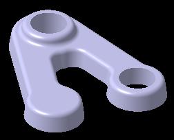
168 Reordering Features You will learn how to reorder features making up a 3D part Pad after mirror operation Pad moved before mirror 168
169 Why Reordering Features? Reordering features allows you to correct a part so that your design intent is preserved One cylinder Design changes Changes as well as features created later in the process can easily be incorporated into the part structure taking into account the design intent Two cylinders when moved before the mirror operation 169
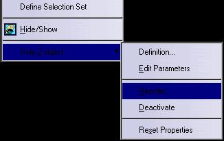
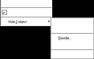

170 Reordering Features... 3 Update the Part 1 Select Reorder in the feature contextual menu 2 Select the feature after which the hole will be placed 170


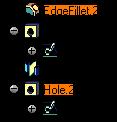
171 Reordering Features 1 Right click the feature to be reordered to get a contextual menu 2 Select Reorder Pad.2 was incorrectly created after the mirror operation, so we must reorder the pad before the mirror You get: 3 Select Pad.1 in the specification tree as the feature to reorder after (Pad.1 is shown as the preview) 171

172 Modifying Features You will learn how to modify parameters of 3D features Modified Pad 172


173 Why Modifying Features? Often, as the design matures, the initial configuration of a part needs refinement through the modification of feature parameters or the addition/removal of features Draft angle Modified pad Pad length 173

174 Modifying Features... 3 Update the Part 1 Double click on the feature to be modified 2 Modify the feature dimensions 174


175 Redefining Feature Parameters 1 Double click the feature or it s specification to edit the feature 2 Modify the draft specifications by double clicking the dimension or entering in the dialog box You get: 3 Next, modify Pad.1 of the part by right clicking the feature in the specification tree and selecting Definition... then modify the dimension directly or through it s dialog box 175


176 Editing Holes 1 Double click on the feature or its specification in the tree to edit hole 2 Change the hole definition in the dialog box or double click on dimensions to modify directly Modify the position dimensions by double clicking them to modify directly You get: You can also reposition a hole without editing it by dragging it to it s new location, even if it s new location is on a different face 176
 3 Modify the constraint 4 Leave the sketcher by selecting the Exit icon")
 (2) (3) You get :")
177 Sketch Edition During Pad Edition 1 Double click on the pad to be modified (1) 3 Modify the constraint 4 Leave the sketcher by selecting the Exit icon (4) 2 Select the sketch icon from the dialog box in order to activate the sketcher 5 If necessary, select the Update All icon (5) (2) (3) You get : 177
 3 Select the replacing sketch (3) 4")
 (5) You get :")
178 Replacing a Sketch During Pad Edition 1 Double click on the pad to be modified (1) 3 Select the replacing sketch (3) 4 Select OK (4) 2 Select the sketch field from the dialog box 5 If necessary, select the Update All icon (2) (5) You get : 178


179 Additional Information... Deleting features CATIA allows you to delete features simply by selecting the feature to delete and selecting delete in the Edit menu (or right clicking the selected feature and selecting delete in the contextual menu Deleting a feature produces a dialog that can be expanded to show the impact of deleting the feature: it allows you to manage the deletion and actually gives you the opportunity to replace it by another element Deleting a sketch 179
Basic Features. In this lesson you will learn how to create basic CATIA features. Lesson Contents: CATIA V5 Fundamentals- Lesson 3: Basic Features
 Basic Features In this lesson you will learn how to create basic CATIA features. Lesson Contents: Case Study: Basic Features Design Intent Stages in the Process Determine a Suitable Base Feature Create
Introduction to CATIA V5
 Introduction to CATIA V5 Release 17 (A Hands-On Tutorial Approach) Kirstie Plantenberg University of Detroit Mercy SDC PUBLICATIONS Schroff Development Corporation www.schroff.com Better Textbooks. Lower
M TE S Y S LT U A S S A
 Dress-Up Features In this lesson you will learn how to place dress-up features on parts. Lesson Contents: Case Study: Timing Chain Cover Design Intent Stages in the Process Apply a Draft Create a Stiffener
Table of Contents. Dedication Preface. Chapter 1: Introduction to CATIA V5-6R2015. Chapter 2: Drawing Sketches in the Sketcher Workbench-I.
 Table of Contents Dedication Preface iii xvii Chapter 1: Introduction to CATIA V5-6R2015 Introduction to CATIA V5-6R2015 1-2 CATIA V5 Workbenches 1-2 System Requirements 1-4 Getting Started with CATIA
CAD-CAM-CAE Examples
 CAD-CAM-CAE Examples example title: example number: example level: CAx system: Related material part with TÁMOP Job Description: Shaft type component (CAD) ÓE-A06a basic - medium - advanced CATIA v5 CAD
Lesson 6 2D Sketch Panel Tools
 Lesson 6 2D Sketch Panel Tools Inventor s Sketch Tool Bar contains tools for creating the basic geometry to create features and parts. On the surface, the Geometry tools look fairly standard: line, circle,
SolidWorks 95 User s Guide
 SolidWorks 95 User s Guide Disclaimer: The following User Guide was extracted from SolidWorks 95 Help files and was not originally distributed in this format. All content 1995, SolidWorks Corporation Contents
Education Curriculum Combined Specialist
 Education Curriculum Combined Specialist Invest your time in imagining next generation designs. Here s what we will teach you to give shape to your imagination. CATIA Combined Specialist Course CATIA Mechanical
CATIA Instructor-led Live Online Training Program
 Course Outline Introduction & Understanding to CATIA Environment Introduction & Understanding to CATIA interface Starting new file Understand the Sketcher workbench of CATIA V5 Start a new file in the
Module 2.1, 2.2 Review. EF101 Analysis & Skills Module 2.3. Sketched Features and Operations. On-line Help Two Locations
 EF101 Analysis & Skills Module 2.3 Engineering Graphics Revolved Features Placed Features Work Features Module 2.1, 2.2 Review What are the three types of operations for adding features to the base feature?
Prismatic Machining Preparation Assistant
 Prismatic Machining Preparation Assistant Overview Conventions What's New Getting Started Open the Design Part and Start the Workbench Automatically Create All Machinable Features Open the Manufacturing
SolidWorks Part I - Basic Tools SDC. Includes. Parts, Assemblies and Drawings. Paul Tran CSWE, CSWI
 SolidWorks 2015 Part I - Basic Tools Includes CSWA Preparation Material Parts, Assemblies and Drawings Paul Tran CSWE, CSWI SDC PUBLICATIONS Better Textbooks. Lower Prices. www.sdcpublications.com Powered
CREO.1 MODELING A BELT WHEEL
 CREO.1 MODELING A BELT WHEEL Figure 1: A belt wheel modeled in this exercise. Learning Targets In this exercise you will learn: Using symmetry when sketching Using pattern to copy features Using RMB when
Part 8: The Front Cover
 Part 8: The Front Cover 4 Earpiece cuts and housing Lens cut and housing Microphone cut and housing The front cover is similar to the back cover in that it is a shelled protrusion with screw posts extruding
Chapter 2. Drawing Sketches for Solid Models. Learning Objectives
 Chapter 2 Drawing Sketches for Solid Models Learning Objectives After completing this chapter, you will be able to: Start a new template file to draw sketches. Set up the sketching environment. Use various
Using Siemens NX 11 Software. The connecting rod
 Using Siemens NX 11 Software The connecting rod Based on a Catia tutorial written by Loïc Stefanski. At the end of this manual, you should obtain the following part: 1 Introduction. Start NX 11 and open
Training Guide Basics
 Training Guide Basics 2014, Missler Software. 7, Rue du Bois Sauvage F-91055 Evry, FRANCE Web: www.topsolid.com E-mail: info@topsolid.com All rights reserved. TopSolid Design Basics This information is
< Then click on this icon on the vertical tool bar that pops up on the left side.
 Pipe Cavity Tutorial Introduction The CADMAX Solid Master Tutorial is a great way to learn about the benefits of feature-based parametric solid modeling with CADMAX. We have assembled several typical parts
Product Modelling in Solid Works
 Product Modelling in Solid Works In the following exercise you will use solid works to construct the computer mouse shown opposite. In this exercise you will use a number of advanced features to achieve
Lesson 4 Holes and Rounds
 Lesson 4 Holes and Rounds 111 Figure 4.1 Breaker OBJECTIVES Sketch arcs in sections Create a straight hole through a part Complete a Sketched hole Understand the Hole Tool Use Info to extract information
Shaft Hanger - SolidWorks
 ME-430 INTRODUCTION TO COMPUTER AIDED DESIGN Shaft Hanger - SolidWorks BY: DR. HERLI SURJANHATA ASSIGNMENT Submit TWO isometric views of the Shaft Hanger with your report, 1. Shaded view of the trimetric
Modeling Basic Mechanical Components #1 Tie-Wrap Clip
 Modeling Basic Mechanical Components #1 Tie-Wrap Clip This tutorial is about modeling simple and basic mechanical components with 3D Mechanical CAD programs, specifically one called Alibre Xpress, a freely
Datum Tutorial Part: Cutter
 Datum Tutorial Part: Cutter Objective: Learn to apply Datums in different ways Directions 1. Datum Axis Creation a. First we need to create a center axis for the cutter b. Model Tab > Datum > Select Axis
Feature-Based Modeling and Optional Advanced Modeling. ENGR 1182 SolidWorks 05
 Feature-Based Modeling and Optional Advanced Modeling ENGR 1182 SolidWorks 05 Today s Objectives Feature-Based Modeling (comprised of 2 sections as shown below) 1. Breaking it down into features Creating
Alternatively, the solid section can be made with open line sketch and adding thickness by Thicken Sketch.
 Sketcher All feature creation begins with two-dimensional drawing in the sketcher and then adding the third dimension in some way. The sketcher has many menus to help create various types of sketches.
Beginner s Guide to SolidWorks Alejandro Reyes, MSME Certified SolidWorks Professional and Instructor SDC PUBLICATIONS
 Beginner s Guide to SolidWorks 2008 Alejandro Reyes, MSME Certified SolidWorks Professional and Instructor SDC PUBLICATIONS Schroff Development Corporation www.schroff.com www.schroff-europe.com Part Modeling
Siemens NX11 tutorials. The angled part
 Siemens NX11 tutorials The angled part Adaptation to NX 11 from notes from a seminar Drive-to-trial organized by IBM and GDTech. This tutorial will help you design the mechanical presented in the figure
for Solidworks TRAINING GUIDE LESSON-9-CAD
 for Solidworks TRAINING GUIDE LESSON-9-CAD Mastercam for SolidWorks Training Guide Objectives You will create the geometry for SolidWorks-Lesson-9 using SolidWorks 3D CAD software. You will be working
1. Open the Feature Modeling demo part file on the EEIC website. Ask student about which constraints needed to Fully Define.
 BLUE boxed notes are intended as aids to the lecturer RED boxed notes are comments that the lecturer could make Control + Click HERE to view enlarged IMAGE and Construction Strategy he following set of
Engineering & Computer Graphics Workbook Using SolidWorks 2014
 Engineering & Computer Graphics Workbook Using SolidWorks 2014 Ronald E. Barr Thomas J. Krueger Davor Juricic SDC PUBLICATIONS Better Textbooks. Lower Prices. www.sdcpublications.com Powered by TCPDF (www.tcpdf.org)
Graz University of Technology CATIA V5. Basic Training. CAx in Automotive and Engine Technology Dipl.-Ing. Dr.techn.
 CATIA V5 Basic Training CAx in Automotive and Engine Technology 313.067 Dipl.-Ing. Dr.techn. Michael Lang Preface The present script includes an introduction of the main features in the 3D design software
1.6.7 Add Arc Length Dimension Modify Dimension Value Check the Sketch Curve Connectivity
 Contents 2D Sketch... 1 1.1 2D Sketch Introduction... 1 1.1.1 2D Sketch... 1 1.1.2 Basic Setting of 2D Sketch... 2 1.1.3 Exit 2D Sketch... 4 1.2 Draw Common Geometry... 5 2.2.1 Points... 5 2.2.2 Lines
Introduction to Autodesk Inventor for F1 in Schools (Australian Version)
") Introduction to Autodesk Inventor for F1 in Schools (Australian Version) F1 in Schools race car In this course you will be introduced to Autodesk Inventor, which is the centerpiece of Autodesk s Digital
Introduction to Autodesk Inventor for F1 in Schools (Australian Version) F1 in Schools race car In this course you will be introduced to Autodesk Inventor, which is the centerpiece of Autodesk s Digital
Introducing SolidWorks
 Introducing SolidWorks SAAST Robotics 2008 SolidWorks Software Visually-based 3-D Mechanical design software Engineers and Designers use it to: Quickly sketch out ideas Experiment with features, dimensions
Creo Revolve Tutorial
 Creo Revolve Tutorial Setup 1. Open Creo Parametric Note: Refer back to the Creo Extrude Tutorial for references and screen shots of the Creo layout 2. Set Working Directory a. From the Model Tree navigate
J. La Favre Fusion 360 Lesson 2 April 19, 2017
 In this lesson, you will create a round plate with 12 counter-bored holes to fit 6-32 socket head screws. A counter-bored hole has two diameters, one to fit the threaded part of the screw and the other
CATIA LABSHEETS ZEIT 1501: Engineering Practice and Design. Dr. Hemant Kumar Singh Dr. Khairul Alam
 CATIA LABSHEETS ZEIT 1501: Engineering Practice and Design Dr. Hemant Kumar Singh Dr. Khairul Alam 2014 Important Information on CATIA Drawing Submissions: 2014 Please take note of the following: (a) (b)
From the above fig. After sketching the path and profile select the sweep command First select the profile from property manager tree And then select
 Chapter 5 In sweep command there is a) Two sketch profiles b) Two path c) One sketch profile and one path The sweep profile is used to create threads springs circular things and difficult geometry. For
Engineering & Computer Graphics Workbook Using SOLIDWORKS
 Engineering & Computer Graphics Workbook Using SOLIDWORKS 2017 Ronald E. Barr Thomas J. Krueger Davor Juricic SDC PUBLICATIONS Better Textbooks. Lower Prices. www.sdcpublications.com Powered by TCPDF (www.tcpdf.org)
Software Development & Education Center NX 8.5 (CAD CAM CAE)
") Software Development & Education Center NX 8.5 (CAD CAM CAE) Detailed Curriculum Overview Intended Audience Course Objectives Prerequisites How to Use This Course Class Standards Part File Naming Seed
Software Development & Education Center NX 8.5 (CAD CAM CAE) Detailed Curriculum Overview Intended Audience Course Objectives Prerequisites How to Use This Course Class Standards Part File Naming Seed
ME Week 2 Project 2 Flange Manifold Part
 1 Project 2 - Flange Manifold Part 1.1 Instructions This project focuses on additional sketching methods and sketching commands. Revolve and Work features are also introduced. The part being modeled is
AEROPLANE. Create a New Folder in your chosen location called Aeroplane. The four parts that make up the project will be saved here.
 AEROPLANE Prerequisite Knowledge Previous knowledge of the following commands is required to complete this lesson. Sketching (Line, Rectangle, Arc, Add Relations, Dimensioning), Extrude, Assemblies and
1. Create a 2D sketch 2. Create geometry in a sketch 3. Use constraints to position geometry 4. Use dimensions to set the size of geometry
 2.1: Sketching Many features that you create in Fusion 360 start with a 2D sketch. In order to create intelligent and predictable designs, a good understanding of how to create sketches and how to apply
Designing in Context. In this lesson, you will learn how to create contextual parts driven by the skeleton method.
 Designing in Context In this lesson, you will learn how to create contextual parts driven by the skeleton method. Lesson Contents: Case Study: Designing in context Design Intent Stages in the Process Clarify
SolidWorks Design & Technology
 SolidWorks Design & Technology Training Course at PHSG Ex 5. Lego man Working with part files 8mm At first glance the Lego man looks complicated but I hope you will see that if you approach a project one
Lesson 4 Extrusions OBJECTIVES. Extrusions
 Lesson 4 Extrusions Figure 4.1 Clamp OBJECTIVES Create a feature using an Extruded protrusion Understand Setup and Environment settings Define and set a Material type Create and use Datum features Sketch
Digital Camera Exercise
 Commands Used New Part This lesson includes Sketching, Extruded Boss/Base, Extruded Cut, Fillet, Chamfer and Text. Click File, New on the standard toolbar. Select Part from the New SolidWorks Document
FUSION 360: SKETCHING FOR MAKERS
 FUSION 360: SKETCHING FOR MAKERS LaDeana Dockery 2017 MAKEICT Wichita, KS 1 Table of Contents Interface... 1 File Operations... 1 Opening Existing Models... 1 Mouse Navigation... 1 Preferences... 2 Navigation
Sash Clamp. Sash Clamp SW 2015 Design & Communication Graphics Page 1.
 Sash Clamp 1 Introduction: The Sash clamp consists of nine parts. In creating the clamp we will be looking at the improvements made by SolidWorks in linear patterns, adding threads and in assembling the
Getting Started. Before You Begin, make sure you customized the following settings:
 Getting Started Getting Started Before getting into the detailed instructions for using Generative Drafting, the following tutorial aims at giving you a feel of what you can do with the product. It provides
Solid Part Four A Bracket Made by Mirroring
 C h a p t e r 5 Solid Part Four A Bracket Made by Mirroring This chapter will cover the following to World Class standards: Sketch of a Solid Problem Draw a Series of Lines Finish the 2D Sketch Extrude
Part 2: Earpiece. Insert Protrusion (Internal Sketch) Hole Patterns Getting Started with Pro/ENGINEER Wildfire. Round extrusion.
 Hole Patterns Getting Started with Pro/ENGINEER Wildfire. Round extrusion.") Part 2: Earpiece 4 Round extrusion Radial pattern Chamfered edge To create this part, you'll use some of the same extrusion techniques you used in the lens part. The only difference in this part is that
Part 2: Earpiece 4 Round extrusion Radial pattern Chamfered edge To create this part, you'll use some of the same extrusion techniques you used in the lens part. The only difference in this part is that
Rotational Patterns of Sketched Features Using Datum Planes On-The-Fly
 Rotational Patterns of Sketched Features Using Datum Planes On-The-Fly Patterning a sketched feature (such as a slot, rib, square, etc.,) requires a slightly different technique. Why can t we create a
Table of Contents. Lesson 1 Getting Started
 NX Lesson 1 Getting Started Pre-reqs/Technical Skills Basic computer use Expectations Read lesson material Implement steps in software while reading through lesson material Complete quiz on Blackboard
How to Build a Game Console. David Hunt, PE
 How to Build a Game Console David Hunt, PE davidhunt@outdrs.net Covering: Drafts Fillets Shells Patterns o Linear o Circular Using made-for-the-purpose sketches to define reference geometry Using reference
Inventor-Parts-Tutorial By: Dor Ashur
 Inventor-Parts-Tutorial By: Dor Ashur For Assignment: http://www.maelabs.ucsd.edu/mae3/assignments/cad/inventor_parts.pdf Open Autodesk Inventor: Start-> All Programs -> Autodesk -> Autodesk Inventor 2010
Advance Dimensioning and Base Feature Options
 Chapter 4 Advance Dimensioning and Base Feature Options Learning Objectives After completing this chapter you will be able to: Dimension the sketch using the autodimension sketch tool. Dimension the sketch
Creo Parametric 2.0: Introduction to Solid Modeling. Creo Parametric 2.0: Introduction to Solid Modeling
 Creo Parametric 2.0: Introduction to Solid Modeling 1 2 Part 1 Class Files... xiii Chapter 1 Introduction to Creo Parametric... 1-1 1.1 Solid Modeling... 1-4 1.2 Creo Parametric Fundamentals... 1-6 Feature-Based...
Activity 1 Modeling a Plastic Part
 Activity 1 Modeling a Plastic Part In this activity, you will model a plastic part. When completed, your plastic part should look like the following two illustrations. While building this model, take time
The Revolve Feature and Assembly Modeling
 The Revolve Feature and Assembly Modeling PTC Clock Page 52 PTC Contents Introduction... 54 The Revolve Feature... 55 Creating a revolved feature...57 Creating face details... 58 Using Text... 61 Assembling
Advanced Modeling Techniques Sweep and Helical Sweep
 Advanced Modeling Techniques Sweep and Helical Sweep Sweep A sweep is a profile that follows a path placed on a datum. It is important when creating a sweep that the designer plans the size of the path
MN Modelling Objects and Creating Manufacturing Strategy
 Abstract This document and the accompanying files describe the process of modelling a bell housing jig using the 3D software Catia V5. The manufacturing process by which the bell housing would be created
Introduction to SolidWorks Introduction to SolidWorks
 Introduction to SolidWorks Introduction to SolidWorks SolidWorks is a powerful 3D modeling program. The models it produces can be used in a number of ways to simulate the behaviour of a real part or assembly
Conquering the Rubicon
 Autodesk Inventor R10 Fundamentals: Conquering the Rubicon Elise Moss SDC PUBLICATIONS Schroff Development Corporation www.schroff.com www.schroff-europe.com Schroff Development Corporation P.O. Box 1334
Generative Drafting (ISO)
") CATIA Training Foils Generative Drafting (ISO) Version 5 Release 8 January 2002 EDU-CAT-E-GDRI-FF-V5R8 1 Table of Contents (1/2) 1. Introduction to Generative Drafting Generative Drafting Workbench Presentation
CATIA Training Foils Generative Drafting (ISO) Version 5 Release 8 January 2002 EDU-CAT-E-GDRI-FF-V5R8 1 Table of Contents (1/2) 1. Introduction to Generative Drafting Generative Drafting Workbench Presentation
Below are the desired outcomes and usage competencies based on the completion of Project 4.
 Engineering Design with SolidWorks Project 4 Below are the desired outcomes and usage competencies based on the completion of Project 4. Project Desired Outcomes: An understanding of the customer s requirements
CATIA V5 Workbook Release V5-6R2013
 CATIA V5 Workbook Release V5-6R2013 Richard Cozzens SDC PUBLICATIONS Better Textbooks. Lower Prices. www.sdcpublications.com Powered by TCPDF (www.tcpdf.org) Visit the following websites to learn more
Engineering Technology
 Engineering Technology Introduction to Parametric Modelling Engineering Technology 1 See Saw Exercise Part 1 Base Commands used New Part This lesson includes Sketching, Extruded Boss/Base, Hole Wizard,
Generative Drafting Overview What's New Getting Started User Tasks
 Generative Drafting Overview Conventions What's New Getting Started Defining the Drawing Sheet Part Drawing Opening a Part Creating a Front View Creating a Projection View Creating a Section View Creating
Introduction to ANSYS DesignModeler
 Lecture 4 Planes and Sketches 14. 5 Release Introduction to ANSYS DesignModeler 2012 ANSYS, Inc. November 20, 2012 1 Release 14.5 Preprocessing Workflow Geometry Creation OR Geometry Import Geometry Operations
Part Design. Sketcher - Basic 1 13,0600,1488,1586(SP6)
") Part Design Sketcher - Basic 1 13,0600,1488,1586(SP6) In this exercise, we will learn the foundation of the Sketcher and its basic functions. The Sketcher is a tool used to create two-dimensional (2D)
Part Design Sketcher - Basic 1 13,0600,1488,1586(SP6) In this exercise, we will learn the foundation of the Sketcher and its basic functions. The Sketcher is a tool used to create two-dimensional (2D)
with Creo Parametric 4.0
 Parametric Modeling with Creo Parametric 4.0 An Introduction to Creo Parametric 4.0 NEW Contains a new chapter on 3D Printing Randy H. Shih SDC PUBLICATIONS Better Textbooks. Lower Prices. www.sdcpublications.com
Creo Parametric 4.0 Basic Design
 Creo Parametric 4.0 Basic Design Contents Table of Contents Introduction...1 Objective of This Textbook...1 Textbook Outline...2 Textbook Conventions...3 Exercise Files...3 System Configuration...4 Notes
Module 1H: Creating an Ellipse-Based Cylindrical Sheet-metal Lateral Piece
 Inventor (10) Module 1H: 1H- 1 Module 1H: Creating an Ellipse-Based Cylindrical Sheet-metal Lateral Piece In this Module, we will learn how to create an ellipse-based cylindrical sheetmetal lateral piece
Introduction to Sheet Metal Features SolidWorks 2009
 SolidWorks 2009 Table of Contents Introduction to Sheet Metal Features Base Flange Method Magazine File.. 3 Envelopment & Development of Surfaces.. 14 Development of Transition Pieces.. 23 Conversion to
WEEK 5: Shaft Modeling (C51X01, C51X02) Revolved Features, Chamfer
 Revolved Features, Chamfer") WEEK 5: Shaft Modeling (C51X01, C51X02) Revolved Features, Chamfer 1. Creating the Shaft Model 1. File> New> Part, Name: C51X01> OK 2. Insert> Revolve> Placement> Define> select TOP datum plane> Sketch
WEEK 5: Shaft Modeling (C51X01, C51X02) Revolved Features, Chamfer 1. Creating the Shaft Model 1. File> New> Part, Name: C51X01> OK 2. Insert> Revolve> Placement> Define> select TOP datum plane> Sketch
Module 1C: Adding Dovetail Seams to Curved Edges on A Flat Sheet-Metal Piece
 1 Module 1C: Adding Dovetail Seams to Curved Edges on A Flat Sheet-Metal Piece In this Module, we will explore the method of adding dovetail seams to curved edges such as the circumferential edge of a
Cube in a cube Fusion 360 tutorial
 Cube in a cube Fusion 360 tutorial n Before using these instructions, it is helpful to watch this video screencast of the CAD drawing actually being done in the software. Click to link to the video tutorial.
Training Guide Sheet Metal Basics
 Training Guide Sheet Metal Basics 2015, Missler Software. 7, Rue du Bois Sauvage F-91055 Evry, FRANCE Web: www.topsolid.com E-mail: info@topsolid.com All rights reserved. TopSolid Design Sheet Metal Basics
COMPUTER AIDED ENGINEERING DESIGN (BFF2612) PART DESIGN Sketch Based Features
 PART DESIGN Sketch Based Features") COMPUTER AIDED ENGINEERING DESIGN (BFF2612) PART DESIGN Sketch Based Features by Dr. Mohd Nizar Mhd Razali Faculty of Manufacturing Engineering mnizar@ump.edu.my MODELLING STRATEGIES Determine model type
COMPUTER AIDED ENGINEERING DESIGN (BFF2612) PART DESIGN Sketch Based Features by Dr. Mohd Nizar Mhd Razali Faculty of Manufacturing Engineering mnizar@ump.edu.my MODELLING STRATEGIES Determine model type
SolidWorks Navigation
 SolidWorks Basics SolidWorks Navigation Command Bar Feature Tree Model Window Simple Box Select the Front plane Create a new sketch Create a Center Rectangle from the origin Smart Dimension the length
Toothbrush Holder. A drawing of the sheet metal part will also be created.
 Prerequisite Knowledge Previous knowledge of the following commands is required to complete this lesson; Sketch (Line, Centerline, Circle, Add Relations, Smart Dimension,), Extrude Boss/Base, and Edit
Parametric Modeling with Creo Parametric 2.0
 Parametric Modeling with Creo Parametric 2.0 An Introduction to Creo Parametric 2.0 Randy H. Shih SDC PUBLICATIONS Schroff Development Corporation Better Textbooks. Lower Prices. www.sdcpublications.com
Getting Started. Chapter. Objectives
 Chapter 1 Getting Started Autodesk Inventor has a context-sensitive user interface that provides you with the tools relevant to the tasks being performed. A comprehensive online help and tutorial system
Sketch-Up Guide for Woodworkers
 W Enjoy this selection from Sketch-Up Guide for Woodworkers In just seconds, you can enjoy this ebook of Sketch-Up Guide for Woodworkers. SketchUp Guide for BUY NOW! Google See how our magazine makes you
Introduction to Circular Pattern Flower Pot
 Prerequisite Knowledge Previous knowledge of the sketching commands Line, Circle, Add Relations, Smart Dimension is required to complete this lesson. Previous examples of Revolved Boss/Base, Cut Extrude,
Explanation of buttons used for sketching in Unigraphics
 Explanation of buttons used for sketching in Unigraphics Sketcher Tool Bar Finish Sketch is for exiting the Sketcher Task Environment. Sketch Name is the name of the current active sketch. You can also
Engineering Design with SolidWorks A Step-by-Step Project Based Approach Utilizing 3D Solid Modeling. David C. Planchard & Marie P.
 Engineering Design with SolidWorks 2003 A Step-by-Step Project Based Approach Utilizing 3D Solid Modeling David C. Planchard & Marie P. Planchard SDC PUBLICATIONS www.schroff.com www.schroff-europe.com
Designing in the context of an assembly
 SIEMENS Designing in the context of an assembly spse01670 Proprietary and restricted rights notice This software and related documentation are proprietary to Siemens Product Lifecycle Management Software
DesignSpark Mechanical. Guidebook
 DesignSpark Mechanical Guidebook 1 Chapter 5 Introduction and Installation and the User Interface of DesignSpark Mechanical 5-1 Introduction of DesignSpark Mechanical DesignSpark Mechanical (DSM in short)
Engineering Design. with SolidWorks A Step-by-Step Project Based Approach Utilizing 3D Solid Modeling
 INSIDE: MultiMedia CD An audio/visual presentation of the tutorial projects Engineering Design with SolidWorks 2010 A Step-by-Step Project Based Approach Utilizing 3D Solid Modeling Introductory Level
Module 1G: Creating a Circle-Based Cylindrical Sheet-metal Lateral Piece with an Overlaying Lateral Edge Seam And Dove-Tail Seams on the Top Edge
 Inventor (10) Module 1G: 1G- 1 Module 1G: Creating a Circle-Based Cylindrical Sheet-metal Lateral Piece with an Overlaying Lateral Edge Seam And Dove-Tail Seams on the Top Edge In Module 1A, we have explored
Made Easy. Jason Pancoast Engineering Manager
 3D Sketching Made Easy Jason Pancoast Engineering Manager Today I have taught you to sketch in 3D. It s as easy as counting ONE, TWO, FIVE...er...THREE! When your sketch only lives in Y and in X, Adding
Module 2: Radial-Line Sheet-Metal 3D Modeling and 2D Pattern Development: Right Cone (Regular, Frustum, and Truncated)
") Inventor (5) Module 2: 2-1 Module 2: Radial-Line Sheet-Metal 3D Modeling and 2D Pattern Development: Right Cone (Regular, Frustum, and Truncated) In this tutorial, we will learn how to build a 3D model
Inventor (5) Module 2: 2-1 Module 2: Radial-Line Sheet-Metal 3D Modeling and 2D Pattern Development: Right Cone (Regular, Frustum, and Truncated) In this tutorial, we will learn how to build a 3D model
GstarCAD Mechanical 2015 Help
 1 Chapter 1 GstarCAD Mechanical 2015 Introduction Abstract GstarCAD Mechanical 2015 drafting/design software, covers all fields of mechanical design. It supplies the latest standard parts library, symbols
5 More Than Straight Lines
 5 We have drawn lines, shapes, even a circle or two, but we need more element types to create designs efficiently. A 2D design is a flat representation of what are generally 3D objects, represented basically
Name: Date Completed: Basic Inventor Skills I
 Name: Date Completed: Basic Inventor Skills I 1. Sketch, dimension and extrude a basic shape i. Select New tab from toolbar. ii. Select Standard.ipt from dialogue box by double clicking on the icon. iii.
Drawing and Assembling
 Youth Explore Trades Skills Description In this activity the six sides of a die will be drawn and then assembled together. The intent is to understand how constraints are used to lock individual parts