Prismatic Machining Preparation Assistant
|
|
|
- Adela Bishop
- 5 years ago
- Views:
Transcription
1 Prismatic Machining Preparation Assistant Overview Conventions What's New Getting Started Open the Design Part and Start the Workbench Automatically Create All Machinable Features Open the Manufacturing View Browse Axial Machinable Features Browse Prismatic Machining Areas User Tasks Globally Create All Machinable Features Locally Create Machinable Features Create an Axial Operation on a Machinable Feature Create a Milling Operation on a Machinable Feature Select Machinable Features Using the Search Command Automatically Create Machining Patterns Create a Machining Pattern on Machinable Features Create a Machining Process for Machinable Features Apply a Machining Process on Machinable Features Associativity of Prismatic Machining Area Workbench Description Toolbars Reference Information Prismatic Machining Area Features Axial Machinable Features Associativity Glossary Index
2 Overview Welcome to the Prismatic Machining Preparation Assistant User's Guide. This guide is intended for users who need to become quickly familiar with the Prismatic Machining Preparation Assistant Version 5 product. This overview provides the following information: Prismatic Machining Preparation Assistant in a Nutshell Before Reading this Guide Getting the Most Out of this Guide Accessing Sample Documents Conventions Used in this Guide. Prismatic Machining Preparation Assistant in a Nutshell Prismatic Machining Preparation Assistant delivers Machinable Features recognition and associated functionalities for preparing a design part for Prismatic Machining. This product assists the NC programmer in making the link between Design and Manufacturing. It provides a set of functionalities that generate all Prismatic Machinable Features of the design part. It builds a real Manufacturing View of the design part with all the drilling and milling features to be machined. Thanks to its Machinable Features Recognition technology, Prismatic Machining Preparation Assistant allows Prismatic Machinable Features creation for all kinds of CATIA Version 5 design parts, including those with no Design Feature specifications, as well as non-catia Version 5 design parts. It is totally integrated with the Prismatic Machining and Advanced Machining products. It dramatically reduces programming times by automatically creating all geometric areas that must be machined with Prismatic Machining operations, reducing time spent in geometry selections. All Machinable Features can be fully machined with Prismatic Machining strategies by creating elementary machining operations or applying more complex machining processes in both drilling and milling domains. Prismatic Machining Preparation Assistant offers the following main capabilities: Automatically creates all Prismatic Machinable Features of a design part Locally creates a Prismatic Machining Feature of a design part Machinable Features integration in Prismatic Machining and Advanced Machining products Management of Recognized Prismatic Machinable Features in Manufacturing View (presentation, edition, highlight, and so on). Before Reading this Guide
3 Before reading this guide, you should be familiar with basic Version 5 concepts such as document windows, standard and view toolbars. Therefore, we recommend that you read the Infrastructure User's Guide that describes generic capabilities common to all Version 5 products. It also describes the general layout of V5 and the interoperability between workbenches. You may also like to read the following complementary product guides, for which the appropriate license is required: Prismatic Machining User's Guide: explains how to machine prismatic parts. NC Manufacturing Infrastructure User's Guide: explains how to use functionalities that are common to all Machining products. Getting the Most Out of this Guide To get the most out of this guide, we suggest that you start reading and performing the step-by-step Getting Started tutorial. This tutorial will show you how to prepare a basic prismatic part for machining. Once you have finished, you should move on to the User Tasks section, which gives more complete information about the product's functionalities. The Reference section provides useful complementary information. The Workbench Description section, which describes the commands that are specific to Prismatic Machining Preparation Assistant, will also certainly prove useful. Accessing Sample Documents To perform the scenarios, you will be using sample documents contained in the doc/online/mpaug_c2/samples or doc/online/mpaug_d2/samples folder. For more information about this, refer to Accessing Sample Documents in the Infrastructure User's Guide.
4 Conventions Certain conventions are used in CATIA, ENOVIA & DELMIA documentation to help you recognize and understand important concepts and specifications. Graphic Conventions The three categories of graphic conventions used are as follows: Graphic conventions structuring the tasks Graphic conventions indicating the configuration required Graphic conventions used in the table of contents Graphic Conventions Structuring the Tasks Graphic conventions structuring the tasks are denoted as follows: This icon... Identifies... estimated time to accomplish a task a target of a task the prerequisites the start of the scenario a tip a warning information basic concepts methodology reference information information regarding settings, customization, etc. the end of a task functionalities that are new or enhanced with this release allows you to switch back to the full-window viewing mode
5 Graphic Conventions Indicating the Configuration Required Graphic conventions indicating the configuration required are denoted as follows: This icon... Indicates functions that are... specific to the P1 configuration specific to the P2 configuration specific to the P3 configuration Graphic Conventions Used in the Table of Contents Graphic conventions used in the table of contents are denoted as follows: This icon... Gives access to... Site Map Split View mode What's New? Overview Getting Started Basic Tasks User Tasks or the Advanced Tasks Workbench Description Customizing Reference Methodology Glossary Index Text Conventions The following text conventions are used: The titles of CATIA, ENOVIA and DELMIA documents appear in this manner throughout the text. File -> New identifies the commands to be used.
6 Enhancements are identified by a blue-colored background on the text. How to Use the Mouse The use of the mouse differs according to the type of action you need to perform. Use this mouse button... Whenever you read... Select (menus, commands, geometry in graphics area,...) Click (icons, dialog box buttons, tabs, selection of a location in the document window,...) Double-click Shift-click Ctrl-click Check (check boxes) Drag Drag and drop (icons onto objects, objects onto objects) Drag Move Right-click (to select contextual menu)
7 Enhanced Functionalities What's New? Pattern creation along with feature recognition You can now create machining patterns and axial machinable features in a single step by setting pattern creation options in the Global Feature Recognition dialog box. Capability to apply Global Feature Recognition on selected faces You can now select faces for global feature recognition (previously it was possible to select bodies only). All the features that open onto selected faces are created. New option to recognize holes or circular pockets/cutouts You can now choose to create holes or circular pocket/cutout features depending on the value of a limiting diameter in the Global Feature Recognition dialog box. Enhanced capacity to recognize features in selected machining direction only If a machining direction is selected, you can now choose to create features that open in that direction only. Capability to create machining patterns that group holes by tolerances retrieved from design features Fitting tolerances defined in design features can be retrieved for machinable axial features and used to group holes with the same tolerance in one pattern when creating machining patterns. Select fewer faces for Local Feature Recognition A machinable feature can now be recognized without selecting all the faces of the feature. Improved feedback for Local Feature Recognition Improved user feedback when locally creating machinable features.
8 Getting Started Before getting into the detailed instructions for using Prismatic Machining Preparation Assistant, this tutorial is intended to give you a feel of what you can accomplish with the product. It provides the following step-by-step scenario that shows you how to use some of the key functionalities. Open the Design Part and Start the Workbench Automatically Create All Machinable Features Open the Manufacturing View Browse Axial Machinable Features Browse Prismatic Machining Areas
9 Open the Design Part and Start the Workbench This first task shows you how to open the part that is to be prepared for machining and start the workbench. 1. Select File > Open then select the SampleMPA.CATPart document. 2. If you are working with Prismatic Machining, select Machining > Prismatic Machining from the Start menu. If you are working with Advanced Machining, select Machining > Advanced Machining from the Start menu. The selected workbench appears. The workbench includes the Prismatic Machining Preparation toolbar. Your design part is displayed in the Setup Editor window along with the manufacturing specification tree.

10
11 Automatically Create All Machinable Features This task shows you how to prepare a design part for manufacturing by automatically creating all recognizable prismatic machinable features. 1. Select the Global Feature Recognition icon. The Global Feature Recognition dialog box appears. 2. Select the part in the 3D view. 3. Select all the Feature checkboxes so that the part will be analyzed for all machinable feature types. 4. Click OK to start the feature recognition process. An information box appears giving the following information: List of input bodies selected Total Number of faces in all input bodies Number of faces used in created features Number of machining features created.

12 All recognized machinable features are added to the Manufacturing View.

13 Open the Manufacturing View This task shows you how to open the Manufacturing View to see the results of the global feature recognition step. 1. Select the Manufacturing View icon in the Machining Features toolbar. 2. The Manufacturing View dialog box appears. Right-click the Manufacturing View object and select the Sort by Machining Features contextual command. The view shows that 6 machinable axial features and 4 prismatic machining areas were created.

14 Browse an Axial Machinable Feature This task shows you how to browse axial machinable features. 1. In the Manufacturing View, select one of the axial machinable features as follows: In the example above, the selected feature is a counterbore hole. It is highlighted in the 3D view. 2. Double click the feature in the tree. A dialog box appears showing the characteristics of the feature.
15

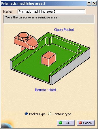
16 Browse a Prismatic Machining Area This task shows you how to browse prismatic machining areas. 1. In the Manufacturing View, select one of the prismatic machining areas as follows: In the example above, the selected feature is a complex step. It is highlighted in the 3D view. 2. Double click the feature in the tree. A dialog box appears showing the characteristics of the feature.
17
18 User Tasks The user tasks you will perform with Prismatic Machining Preparation Assistant involve creating and managing machinable features. Globally Create All Machinable Features Locally Create Machinable Features Create an Axial Operation on a Machinable Feature Create a Milling Operation on a Machinable Feature Select Machinable Features Using the Search Command Automatically Create Machining Patterns Create a Machining Pattern on Machinable Features Create a Machining Process for Machinable Features Apply a Machining Process on Machinable Features Associativity of Prismatic Machining Area
19 Globally Create All Prismatic Machinable Features This task shows you how to prepare a design part for manufacturing by automatically creating all recognizable prismatic machinable features. The SampleMPA.CATPart document should be open. 1. Select the Global Feature Recognition icon. The Global Feature Recognition dialog box appears. 2. Set Selection Type to Body then select the part in the 3D view. The feature recognition takes the associated Body object into account. 3. Select all the Feature checkboxes so that the part will be analyzed for all machinable feature types. To create axial machining features only, just select the Hole checkbox. To create prismatic machining areas only, select all the checkboxes except the Hole checkbox. To create all holes included in a tab hole, select the Enable creation of tab hole components checkbox. A tab (or tabulated) hole is more complex than a Part Design hole in that its hole chain (that is, all faces) do not match a Part Design feature. If the checkbox is not selected, the holes belonging to the tab holes are not created (default behaviour).

20 4. Click OK to start the feature recognition process. All recognized machinable features are added to the Manufacturing View. Note that Selection Type can be set to Face. In this case, all recognized features that open onto selected faces will created. However, suppose a pocket has a child pocket and the top face of upper pocket is selected. The child pocket will not be created as it does not open directly onto the selected face. Graphic and Text Feedback about Machinable Features When you select or move the mouse over a Machinable Axial Feature in the Manufacturing View, feedback in 3D Viewer shows: Highlight of flank RSURs referenced by the Machinable Axial Feature The entry point and entry vector of the feature.

21 Machining direction of a recognized through feature can be reversed by right clicking that feature in Manufacturing View and selecting the Reverse Machining Direction contextual command. This command is not available for the blind features, as they can be machined in only one direction. This command cannot be accessed if the feature is machined. The identifier of the Machinable Axial Feature is shown as follows: Machinable Axial Feature.1 (Simple Hole Diameter=12mm Depth=20mm) representing in a summary the parameters of the feature. If you rename the feature: MyFeature.1 (Simple Hole Diameter=12mm Depth=20mm) Both the graphical representation and the feature in the Manufacturing View are associative and always up-to-date, positioned and filled according to design changes. When geometry can no longer be retrieved from a feature (referenced RSURs are no longer in Design Part, for example) no user representation is displayed. Advanced Parameters The Advanced tab page of the Global Feature Recognition dialog box contains a number of parameters for specific processing.

22 Machining Direction You can specify a machining direction by selecting a face, a line or an edge. Created features will then have a machining axis parallel to the selected direction. By specifying a machining direction, you can choose to create features that open in that direction only. For example, this may correspond to the machining direction of a particular machine setup. If no machining direction is selected, the Create features only in this direction checkbox cannot be selected. Hole / Pocket or Cutout You can choose to create holes or circular pocket/cutout features depending on the value assigned for the maximum hole diameter. Using this capability: large diameter holes can be created as Pockets small diameter intersecting holes can be created as Holes instead of a single complex pocket. Make sure you have selected the appropriate Feature type in the Basic tab page (for example, if you want to recognize a hole as a pocket, select the Hole and Complex Pocket checkboxes or just the Complex Pocket checkbox).


23 Ignore Tapered Hole Component You can choose to ignore the fact that the hole type is tapered during feature recognition. In this way, you can force chamfered holes to be recognized as simple holes. Chamfered hole: Recognized hole: Selection of Bodies One or more Bodies can be selected. For feature recognition, the In-Work object must be either a Body or the last component of a Body. For example, in the figures below: if you want to use Body.2 for feature recognition, the In-Work object must be either Body.2 or Hole.2. Body.2 and Hole.1 are valid In-Work objects. The identifier of the In-Work object is underlined in the tree.
. 3.")
24 Locally Create a Machinable Feature This task shows you how to locally create a prismatic machinable feature in a design part. The SampleMPA.CATPart document should be open. 1. Select the Local Feature Recognition icon. The Local Feature Recognition dialog box appears. 2. Select the type of feature to be recognized using the combo (Complex Step, for example). 3. Click the Faces to Process: No selection field, then in the 3D view locally select one of the contour faces of the complex step:


25 In previous releases, all the faces of the feature had to be selected to allow the feature to be recognized. Now, a feature can be recognized by selecting either the bottom face or one or more contour faces. To deselect a selected face, just reselect it. To deselect all selected faces, just click Remove All. 4. Click Recognize. An information box appears giving the following information about the recognized feature: The created feature appears in the Manufacturing View.

26 In the SampleMPA.CAtPart, to create: one of the simple holes, you need to locally select either the bottom or side face one of the counterbored holes, you need to locally select either the bottom or side face the complex cutout, you need to locally select either the bottom or a flank face the complex pocket, you need to locally select either the bottom or a flank face. If needed, you can specify a preferred machining direction for through features by selecting a face, line or an edge. The through features are given a machining axis direction parallel to the selected direction. Unsuccessful Local Feature Recognition In case of local feature recognition failure, an appropriate error message is issued. Whenever possible, the elements that caused the failure are highlighted. Some examples are given below. Feature type does not match. The recognized feature is not of the specified type. You must select at least one face that uniquely belongs to the feature. If you do not select a unique face, feature recognition will fail. Duplicate feature creation. When you try to recognize a feature that is already present in the manufacturing view, no new feature will be created. Non-machinable feature due to very small dimension. When machining parameters such as depth are very small so as to make them non-machinable, such features are not recognized. Non-machinable feature due to invalid face or edge contour. Feature creation is not possible because of the machinability checks applied on face or edge contour during feature creation.

27 Advanced Parameters The Advanced tab page of the Local Feature Recognition dialog box contains a number of parameters for specific processing. For more information, please refer to: Machining Direction Hole / Pocket or Cutout. Tips for Local Creation of Machinable Features with Feature Recognition In general, a feature can be recognized by selecting either the bottom face or one or more contour faces. To recognize a hole, you must select all the faces of the hole that will be machined: flank faces and, in case of a blind hole, the bottom face. Never select the top face.


28 To recognize a feature with fillets, you must select all the fillets to be able to recognize the feature. Note that features surrounded by convex fillets are not considered as prismatic features and are not managed by the feature recognition capability. In all cases, selection of non-adjacent faces will not allow feature recognition. In the image below, selection of all the red faces will not recognize a complex step feature.


29 In the case of intersecting holes, feature recognition will create as many holes as separate surfaces. In the image below, three features are recognized: one for each surface color. The blue and yellow surfaces do not generate a single machining feature.

30 Create an Axial Operation on an Axial Machinable Feature This task shows you how to create a Counterboring operation using an axial machinable feature. You can make use of one of the Counterbored Hole features created in the Globally Create All Prismatic Machinable Features task. 1. Select the Manufacturing View icon in the Machining Features toolbar. Use the Sort by Machining Features contextual command to display the desired view. 2.Select a Counterbored Hole feature in the view. 3. Select the Counterboring icon. The Counterboring dialog box appears. The operation is initialized with the feature geometry as well as default parameters for machining strategy, feeds and speeds, and tool. You can edit any of these values, if desired. 4.Select the Tool tab page and choose a suitable Counterbore tool according to the feature characteristics displayed in the Geometry page.


31 5. Click the Replay icon to verify the tool path. 6.Click OK to create the Counterboring operation. The operation is added to the Manufacturing View and to the program in the PPR tree.

32 Create a Milling Operation on a Prismatic Machining Area This task shows you how to create a pocketing operation on a prismatic machining area. You can make use of the Complex Step feature created in the Locally Create a Machinable Feature task. 1. Select the Manufacturing View icon in the Machining Features toolbar. Use the Sort by Machining Features contextual command to display the desired view. 2. Select the Complex Step feature in the view. 3. Select the Pocketing icon. The Pocketing dialog box appears. 4. The operation is initialized with the feature geometry as well as default parameters for machining strategy, feeds and speeds, and tool. You can edit any of these values, if desired. 5. Click the Replay icon to verify the tool path.


33 6. Click OK to create the pocketing operation. The operation is added to the Manufacturing View and to the program in the PPR tree.

34 Select Machinable Features Using the Search Command This task shows you how to select machinable features by means of search criteria. Features selected in this way can be used for: creating machining operations machining processes machining patterns. Open the Manufacturing View with the result of the Globally Create All Machinable Features task. 1. Select the Edit>Search command or run the command using the Ctrl+F shortcut. The Search dialog box appears. 2. Select the Advanced tab. 3. Set the Workbench, Type and Attribute search criteria as shown below. 4. To find all axial machinable features with a counterbore diameter of at least 10mm, specify the following search criteria in the dialog box that appears. Click OK. 5. Click the Search icon. The search result is displayed in the dialog box.

35 6. Click OK to select all the features corresponding to the search criteria. They are highlighted in the Part and in the Manufacturing View. A description of all feature attributes is given in Prismatic Machining Areas and Axial Machining Features.

36 Automatically Create Machining Patterns This task shows you how to automatically create axial machinable features and a machining pattern in a single step. Open the HoleMakingOperations.CATPart document, then select the desired Machining workbench from the Start menu. 1. Select the Global Feature Recognition icon. The Global Feature Recognition dialog box appears. 2. In the Basic tab page, select the Hole checkbox to create axial machinable features only. Select the top face of the part in the 3D view. 6. In the Pattern tab page, set the parameters for pattern creation as follows.


37 With these parameters you will create a pattern on threaded holes whose diameter is included in a specified range of diameters (that is, between 17 and 20mm). 7. Select the Manufacturing View icon and display the view sorted by patterns. The created machining pattern is displayed.
38 8. Double click the machining pattern node to display the Machining pattern dialog box to obtain more information about the pattern.
39 Geometry Considerations for Pattern Creation Pattern creation operates on a set of axial features selected from the Manufacturing View, a set of faces, or an entire body. For a set of axial features, pattern creation applies the matching criteria only to that set of features. For a set of planar faces, pattern creation applies the matching criteria to all axial features from each face in the set. Note that all features in a pattern will have identical axes. If a reference direction is defined, the matching criteria only applies to axial machinable features parallel to this axis. For a set of non-planar faces, pattern creation applies the matching criteria to all axial features from each face in the set. Features in the pattern can have different axes. If a reference direction is defined, automatic pattern creation only applies to axial machinable features parallel to this axis. For a body, pattern creation applies the matching criteria to all axial features. Note that all features in a pattern will have identical axes. If a reference direction is defined, automatic pattern creation only applies to axial machinable features parallel to this axis. Using Tolerances in Pattern Creation You can retrieve the fitting tolerances defined in design features when machinable axial features are created. You can match these tolerance values in the pattern creation functionality. The Tolerance Value checkbox for matching the fitting tolerance for pattern creation. You can create patterns of holes having same tolerance values. Matching is done for both tabulated (H7, and so on) as well as minimum/maximum tolerance values. Features having the same tolerance values are grouped in the same pattern. Other holes, for which the tolerance value is not defined, will form a separate pattern. The fitting tolerance value is retrieved and information is displayed to user: in the dialog box of the Machinable axial feature:

40 in the Manufacturing View on the created pattern:

41 Create a Machining Pattern on Machinable Features This task shows you how to create a machining pattern on machinable features. You can make use of the features created in the Globally Create All Prismatic Machinable Features task. 1. Select the Pattern Creation icon. The Pattern Creation dialog box appears. 2. Set Selection Type to Body then select the part in the 3D view. The pattern creation will take the associated Body object into account.
42 2. Click the Machining direction field, then select a geometric element to specify the machining direction (for example, selecting a face as shown means that the machining direction will be taken perpendicular to that face). Only those axial machinable features in the specified machining direction will be taken into account for the pattern. 3. Click OK to create the machining pattern. You can use the Sort by Patterns contextual command to check that the pattern is added to the Manufacturing View. 4. Double-click the pattern identifier to display the Machining Pattern dialog box.


43 The pattern is visualized in the part:


44 Create a Machining Process for Machinable Features This task shows how to create a machining process that will be used to apply a sequence of axial machining operations to machinable features. More information about creating machining processes with formula, checks and tool queries is available in Create a Machining Process in the NC Manufacturing Infrastructure User's Guide. 1. Select the Machining Process View icon. The Machining Process View dialog box appears. 2. Select the Machining Process icon. The dialog box is updated with a new machining process as shown. 3. Select the Spot Drilling icon. The Operation Definition dialog box appears, if the Start Edit mode is selected in the Tools > Options > Machining > Operation settings. 4. Just click OK to add a reference Spot Drilling operation to the machining process. You can associate Formulas or Checks to this reference operation and specify a Tool Query. 5. In the same way add Drilling and Tapping operations to the machining process by selecting first the Drilling icon then the Tapping icon. The Machining Process View dialog box is updated as shown.


45 6. Double click the Tool Query associated to the Spot Drilling operation. The Tool Query Definition dialog box appears. 7. Select the tool repository ToolsSampleMP using the Look in combo. Define a query to look for a spot drill whose nominal diameter is equal to the diameter of the machining axial feature. Click OK to assign the tool query to the Spot Drilling operation. You can assign simple tool queries to the Drilling and Tapping operations: Name=Drill D10.5 and Name=Tap D12, for example.

46 8. Select File > Save As to save the machining process in a CATProcess document called AxialMachiningProcess1.CATProcess, for example. 9. Right click the Machining Process in the Machining Process View and select the Save in Catalog contextual command. 10. The Save in Catalog dialog box appears. Click the [...] button and specify a new catalog name (catalogaxialmp1.catalog, for example). Click OK to save the machining process as a component in the specified catalog. The following are initialized automatically: family name: Machining Process component name: name given to the machining process using File > Save As. However, you can change family or component in the Catalog Editor workbench. Click here to see how you can organize machining processes in a catalog using the Catalog Editor workbench. For the next step in the procedure, please refer to Apply Machining Process on Machinable Features.


47 Apply a Machining Process on Machinable Features This task shows how to apply a machining process on machinable features. Open the desired CATPart document, then select the desired Machining workbench from the Start menu. 1. Select the Open Catalog icon and open the catalog you created in the previous task: catalogaxialmp1.catalog. 2. Double click the Machining Process family: AxialMachiningProcesses. 3. Double click the Machining Process to be applied: AxialMachiningProcess1.


48 The Insert Object dialog box appears allowing you to apply the machining process. 4. Select the geometry to be machined. This can be one of the following: a design feature a machining pattern an axial machinable feature a machining pattern of axial machinable features a prismatic machining area.


49 Then click OK in the Insert Object dialog box. 5. The program is updated with the operations contained in the machining process: spot drilling drilling tapping. These operations reference the selected geometry and make use of any formula defined in the machining process. In addition, the tool queries are resolved so that each operation references the desired tool.


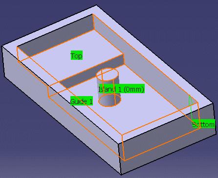
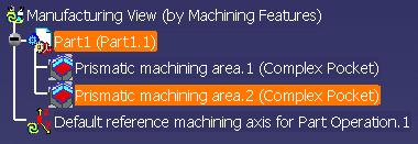
50 Associativity of Prismatic Machining Area This task illustrates the associativity of prismatic machining areas. A prismatic machining area in the manufacturing view has associated geometry in the part document. Typical geometry could be: Top element Bottom element Boundary profile Other Prismatic machining area parameters such as minimum corner radius. If the geometry is modified in the part document, then corresponding parameters and RSUR information for prismatic machining area is updated in manufacturing view to reflect correct values. 1. Select File > Open then select the PrismaticMachining.CATPart document. 2. Select the Global Feature Recognition icon and create a Complex Pocket. 3. Select the Manufacturing View icon in the Machining Features toolbar. Right-click the Manufacturing View object and select the Sort by Machining Features contextual command.

51 4. Double click the created Prismatic machining area in the tree. A dialog box appears showing the characteristics of the feature. 5. Right click the green flank area of the pocket in the sensitive icon and select the Analyze contextual command. The Geometry Analyser appears showing that the status of each of the guide elements making up the pocket is Up to date. Analyze the bottom element in the same way to check that its status is also Up to date.

52 6. Modify the geometry of the pocket (for example by reducing the pocket depth). 7. In the Manufacturing View, analyze the new guide elements and bottom of the pockets. Their status is Up to date, showing the associative nature of the prismatic machining area. Some geometry modifications to a part document can change the feature type. For example: the depth of complex pocket can be changed so that it becomes complex cutout the boundary profile of a complex pocket can be modified in such a way that it becomes a complex step, blind slot or through slot. Such changes are not associative.
53 Workbench Description This section contains the description of the specific commands that are added to your Prismatic Machining or Advanced Machining workbench when Prismatic Machining Preparation Assistant is installed. Toolbars
54 Prismatic Machining Preparation Assistant Toolbars When Prismatic Machining Preparation Assistant is installed the Prismatic Machining Preparation toolbar is added to the Prismatic Machining or Advanced Machining workbench. This toolbar contains the following commands: Global Feature Recognition See Globally Create All Prismatic Machinable Features Local Feature Recognition See Locally Create a Machinable Feature Pattern Creation See Create a Machining Pattern on Machinable Features The commands of the other toolbars of the Prismatic Machining workbench are documented in the Prismatic Machining User's Guide. The commands of the other toolbars of the Advanced Machining workbench are documented in the Advanced Machining User's Guide. It is useful to note that the Machining Features toolbar gives access to the Manufacturing View. Manufacturing View See Open the Manufacturing View.
55 Reference Information Reference information about Prismatic machinable features is given in this section. Prismatic Machining Areas Axial Machinable Features Associativity.
")
56 Prismatic Machining Areas This section provides reference information that is intended to help you: create Prismatic Machining Area features from your design part use Prismatic Machining Area features in the Prismatic Machining or Advanced Machining product: for machining process formulas, checks and tooling queries (for example, to find the appropriate tool to machine the machining area) for search queries.

57 The following Prismatic Machining Area features are supported: complex pocket complex step through slot blind slot complex cutout. Islands can be included Pocket and Step type machinable features. Complex Pocket

58 A complex pocket is a closed multi-sided recess. Specifications on part: A bottom stamp as a hard stamp A top element as a top limit A boundary comprising a series of ordered faces. Results in Prismatic Machining Area: A depth from top to bottom A minimum corner radius A minimum channel width A maximum channel width A top plane A bottom plane A wire frame contour. Complex Step A complex step is an open multi-sided recess. Specifications on part: A bottom stamp as a hard stamp A top element as a top limit A boundary comprising a series of ordered faces with hard and soft qualifications. Through Slot A through slot is a specific step whose contour is two parallel faces as a hard boundary and two other faces as limits. Results in Prismatic Machining Area: A depth from top to bottom A minimum corner radius A minimum channel width A maximum channel width A top plane A bottom plane A wire frame contour with a series of elements qualified as soft and hard. Specifications on part: A bottom stamp as a hard stamp A top element as a top limit A boundary comprising a series of 4 ordered faces with hard and soft qualifications. Blind Slot Results in Prismatic Machining Area: A minimum corner radius A minimum channel width A maximum channel width A top plane A bottom plane A wireframe contour with 4 elements: 2 lines and two other elements.

59 A blind slot is a specific step with two parallel lines and a corner between them. It has an open boundary. Specifications on part: A bottom stamp as a hard stamp A top element as a top limit A boundary comprising a series of 4 ordered faces with hard and soft qualifications. Results in Prismatic Machining Area: A depth from top to bottom A minimum corner radius A minimum channel width A maximum channel width A top plane A bottom plane A wireframe contour with 4 elements: 2 lines, 1 half circle and one other element. Complex Cutout A complex cutout is a multi-sided opening through the part. Specifications on part: A bottom element as a bottom limit A top element as a top limit A boundary comprising a series of ordered faces. Results in Prismatic Machining Area: A depth from top to bottom A minimum corner radius A minimum channel width A maximum channel width A top plane A bottom plane A wireframe contour. Management of Islands Islands can be recognized and associated to Pocket and Step type machinable features. Islands can be associated to features without necessarily sharing a bottom face. See examples below:
60
61 Specifications on part: A bottom stamp as a hard stamp A top element as a top limit A boundary comprising a series of ordered faces. Results in Prismatic Machining Area: A depth from top to bottom A top plane and a bottom plane A wireframe contour.

62 Axial Machinable Features This section provides reference information that is intended to help you: create Axial Machinable Features from your design part use Axial Machinable Features in the Prismatic Machining or Advanced Machining product: for machining process formulas and checks for search queries. A number of hole types are supported. They are identified according to the evaluation of the Hole type attribute as follows. Hole type Name 0 Simple hole 1 Tapered hole 2 Counterbored hole 3 Counterdrilled hole 4 Countersunk hole 5 Unknown
63 Simple Hole Simple hole is characterized by: origin point and direction hole depth and diameter extension type identified according to the evaluation of the Extension attribute: 1 = blind 2 = through for blind holes, bottom type identified according to the evaluation of the Hole bottom type attribute: Flat Bottom V Bottom. for V-bottom holes, bottom angle identified according to the value of the Hole bottom angle attribute. the hole can be threaded. Tapered Hole Tapered hole is characterized by: origin point and direction Counterbored Hole hole depth, diameter and angle Counterbored hole is characterized by: origin point and direction extension type identified according to the evaluation of the Extension attribute: 1 = blind 2 = through. for blind holes, bottom type identified according to the evaluation of the Hole bottom type attribute: Flat Bottom V Bottom. for V-bottom holes, bottom angle identified according to the value of the Hole bottom angle attribute. hole depth and diameter counterbored depth and diameter extension type identified according to the evaluation of the Extension attribute: 1 = blind 2 = through. for blind holes, bottom type identified according to the evaluation of the Hole bottom type attribute: Flat Bottom V Bottom. for V-bottom holes, bottom angle identified according to the value of the Hole bottom angle attribute. the hole can be threaded.
64 Counterdrilled Hole Counterdrilled hole is characterized by: origin point and direction hole depth and diameter countersunk angle counterbored depth and diameter extension type identified according to the evaluation of the Extension attribute: 1 = blind 2 = through. for blind holes, bottom type identified according to the evaluation of the Hole bottom type attribute: Flat Bottom V Bottom. for V-bottom holes, bottom angle identified according to the value of the Hole bottom angle attribute. the hole can be threaded. Countersunk Hole Countersunk hole is characterized by: origin point and direction hole depth and diameter countersunk angle and diameter countersunk depth extension type identified according to the evaluation of the Extension attribute: 1 = blind 2 = through. for blind holes, bottom type identified according to the evaluation of the Hole bottom type attribute: Flat Bottom V Bottom. for V-bottom holes, bottom angle identified according to the value of the Hole bottom angle attribute. the hole can be threaded. Please note that the Countersunk depth can be obtained by means of the following formula: Countersunk depth=(countersunk diameter-hole diameter)/(2*tan(countersunk angle/2)) Threaded Holes The following attributes on the axial machinable feature allow you to access threaded hole information (in
65 the Search function, machining process definition, machining operations that require thread information, and so on). Threaded: True or False Thread diameter (length value) Thread depth (length value) Pitch (length value) Thread direction: 0 = Right-threaded 1 = Left-threaded. The attribute values are read from the design threaded hole (that is, as specification).
66 Associativity of Machinable Axial Features This section describes the associativity behaviour of a Machinable Axial Feature after a design change (modification, move or delete) of the shape referenced by the feature. This is best illustrated by the following scenarios. Scenario 1 Modify the shape of faces referenced by a Machinable Axial Feature (iso-topology) Move the shape of faces referenced by a Machinable Axial Feature (iso-topology) Move the products where faces of a Machinable Axial Feature are referenced. The expected result is as follows. When editing the Machinable Axial Feature all the parameters are updated according to the new specifications. When updating the status of any Drilling operation referencing a Machinable Axial Feature, an Update mask must be displayed on the operation in the PPR tree. When editing any Drilling operation referencing a Machinable Axial Feature, Feature parameters displayed in Geometry tab page are updated according to the new specifications When replaying any Drilling operation referencing a Machinable Axial Feature using the editor, Tool Path replay must show tool path at appropriate location (except if locked). When replaying any Drilling operation referencing a Machinable Axial Feature not using the editor, Tool Path Replay must show tool path at appropriate location (except if locked). Scenario 2 The following design change is made: remove faces of a shape referenced by a Machinable Axial Feature from the Design Part. The expected result is as follows. When updating the status of any Drilling operation referencing a Machinable Axial Feature, an exclamation mask must be displayed on the operation in the PPR tree. Therefore replay is not available.
67 Glossary A approach macro auxiliary command axial machining operation Motion defined for approaching the operation start point A control function such as tool change or machine table rotation. These commands may be interpreted by a specific post-processor. Operation in which machining is done along a single axis and is mainly intended for hole making (drilling, counter boring, and so on). B bottom plane A planar geometric element that represents the bottom surface of an area to machine. It is normal to the tool axis. C clearance macro climb milling conventional milling Motion that involves retracting to a safety plane, a linear trajectory in that plane and then plunging from that plane. Milling in which the advancing tool rotates down into the material. Chips of cut material tend to be thrown behind the tool, which results to give good surface finish. Compare with conventional milling. Milling in which the advancing tool rotates up into the material. Chips of cut material tend to be carried around with the tool, which often impairs good surface finish. Compare with climb milling. D DPM Digital Process for Manufacturing. E extension type Defines the end type of a hole as being through hole or blind. F Facing operation Fault feedrate fixture A surfacing operation in which material is removed in one cut or several axial cuts of equal depth according to a pre-defined machining strategy. Boundaries of the planar area to be machined are soft. Types of faults in material removal simulation are gouge, undercut, and tool clash. Rate at which a cutter advances into a work piece. Measured in linear or angular units (mm/min or mm/rev, for example). Elements used to secure or support the workpiece on a machine.
68 G gouge Area where the tool has removed too much material from the workpiece. H hard high speed milling (HSM) A geometric element (such as a boundary or a bottom face) that the tool cannot pass beyond. Functionality that is supported for Pocketing and Facing operations in which corners and transitions in the tool path are rounded to ensure a smooth and continuous cutting effort. I inward helical island Machining in which motion starts from a point inside the domain to machine and follows paths parallel to the domain boundary towards the center of the domain. Compare with outward helical. Inner domain of a pocket that is to be avoided during machining. It has a closed hard boundary. L linking motion Motion that involves retracting to a safety plane, a linear trajectory in that plane and then plunging from that plane. M machine rotation machining axis system machining feature machining operation machining process An auxiliary command in the program that corresponds to a rotation of the machine table. Reference axis system in which coordinates of points of the tool path are given. A feature instance representing a volume of material to be removed, a machining axis, tolerances, and other technological attributes. These features may be hole type or milling type. Contains all the necessary information for machining a part of the workpiece using a single tool. An ordered list of machining operations, PP instructions and, possibly, machine rotations. It can be used in two ways: to generate a complete subprogram by defining all the operations from geometrical information which will be solved when the machining process is instantiated into another CATProcess file. to generate a subprogram by defining all the operations without any geometrical information (design or manufacturing geometrical features): this way is dedicated to the settings mode. machining tolerance manufacturing process manufacturing program The maximum allowed difference between the theoretical and computed tool path. Defines the sequence of part operations necessary for the complete manufacture of a part. Describes the processing order of the NC entities that are taken into account for tool path computation: machining operations, auxiliary commands and PP instructions.
69 manufacturing view maximum channel width minimum channel width minimum corner radius multi-level operation The set of machining features defined in the part operation. The diameter of the largest circle that fits inside the machining domain boundary (including islands). The maximum channel width may be used to determine the roughing tool. The smallest opening in the boundary profile (including islands) that the tool must pass through in order to completely machine the profile. Limit value: For particular geometrical cases, no minimum channel width exist. In this case the minimum channel width value must be equal to the maximum channel width value. The smallest radius of the Prismatic Machining Area boundary (including islands) that cause a constraint on the tool to be used for machining the domain. The minimum corner radius may be used to determine the finishing tool. Limit value: if an angle is detected on the profile (or islands) the minimum corner radius is 0. Milling operation (such as Pocketing or Profile Contouring) that is done in a series of axial cuts. O offset outward helical Specifies a virtual displacement of a reference geometric element in an operation (such as the offset on the bottom plane of a pocket, for example). Compare with thickness. Machining in which motion starts from a point inside the domain to machine and follows paths parallel to the domain boundary away from the center of the domain. Compare with inward helical. P part operation Links all the operations necessary for machining a part based on a unique part registration on a machine. The part operation links these operations with the associated fixture and set-up entities. pocket An area to be machined that is defined by an open or closed boundary and a bottom plane. The pocket definition may also include a top plane and one or more islands. Pocketing operation A machining operation in which material is removed from a pocket in one or several axial cuts of equal depth according to a pre-defined machining strategy. The tool path style is either Inward helical, Outward helical or Back and forth. Point to Point operation A milling operation in which the tool moves in straight line segments between user-defined points. PP instruction Instructions that control certain functions that are auxiliary to the tool-part relationship. They may be interpreted by a specific post processor. PPR Process Product Resources. Profile Contouring operation A milling operation in which the tool follows a guide curve and possibly other guide elements while respecting user-defined geometric limitations and machining strategy parameters. R retract macro Motion defined for retracting from the operation end point
70 return macro Motion for linking between paths or between levels. It involves retracting to a safety plane, a linear trajectory in that plane and then plunging from that plane. S safety plane set up soft spindle speed stock A plane normal to the tool axis in which the tool tip can move or remain a clearance distance away from the workpiece, fixture or machine. Describes how the part, stock and fixture are positioned on the machine. A geometric element (such as a boundary or a bottom face) that the tool can pass beyond. The angular speed of the machine spindle. Measured in linear or angular units (m/min or rev/min, for example). Workpiece prior to machining by the operations of a part operation. T thickness top plane tool axis tool change tool clash tool path total depth Specifies a thickness of material to be removed by machining. Compare with offset. A planar geometric element that represents the top surface of an area to machine. It is always normal to the associated tool's rotational axis. Center line of the cutter. An auxiliary command in the program that corresponds to a change of tool. Area where the tool collided with the workpiece during a rapid move. The path that the center of the tool tip follows during a machining operation. The total depth including breakthrough distance that is machined in a hole making operation. U undercut Area where the tool has left material behind on the workpiece.
Prasanth. Lathe Machining
 Lathe Machining Overview Conventions What's New? Getting Started Open the Part to Machine Create a Rough Turning Operation Replay the Toolpath Create a Groove Turning Operation Create Profile Finish Turning
Part Design Fundamentals
 Part Design Fundamentals 1 Course Presentation Objectives of the course In this course you will learn basic methods to create and modify solids features and parts Targeted audience New CATIA V5 Users 1
Purdue AFL. CATIA CAM Process Reference Rev. B
 Purdue AFL CATIA CAM Process Reference Rev. B Revision Notes Revision - of this document refers to the CATIA v5r21 deployment of the AFL CATIA Environment. All information contained in this reference document
Generative Drafting Overview What's New Getting Started User Tasks
 Generative Drafting Overview Conventions What's New Getting Started Defining the Drawing Sheet Part Drawing Opening a Part Creating a Front View Creating a Projection View Creating a Section View Creating
Basic Features. In this lesson you will learn how to create basic CATIA features. Lesson Contents: CATIA V5 Fundamentals- Lesson 3: Basic Features
 Basic Features In this lesson you will learn how to create basic CATIA features. Lesson Contents: Case Study: Basic Features Design Intent Stages in the Process Determine a Suitable Base Feature Create
ENGI 7962 Mastercam Lab Mill 1
 ENGI 7962 Mastercam Lab Mill 1 Starting a Mastercam file: Once the SolidWorks models is complete (all sketches are Fully Defined), start up Mastercam and select File, Open, Files of Type, SolidWorks Files,
Figure 1: NC Lathe menu
 Click To See: How to Use Online Documents SURFCAM Online Documents 685)&$0Ã5HIHUHQFHÃ0DQXDO 5 /$7+( 5.1 INTRODUCTION The lathe mode is used to perform operations on 2D geometry, turned on two axis lathes.
Figure 1: NC EDM menu
 Click To See: How to Use Online Documents SURFCAM Online Documents 685)&$0Ã5HIHUHQFHÃ0DQXDO 6 :,5(('0 6.1 INTRODUCTION SURFCAM s Wire EDM mode is used to produce toolpaths for 2 Axis and 4 Axis EDM machines.
SolidWorks Part I - Basic Tools SDC. Includes. Parts, Assemblies and Drawings. Paul Tran CSWE, CSWI
 SolidWorks 2015 Part I - Basic Tools Includes CSWA Preparation Material Parts, Assemblies and Drawings Paul Tran CSWE, CSWI SDC PUBLICATIONS Better Textbooks. Lower Prices. www.sdcpublications.com Powered
M TE S Y S LT U A S S A
 Dress-Up Features In this lesson you will learn how to place dress-up features on parts. Lesson Contents: Case Study: Timing Chain Cover Design Intent Stages in the Process Apply a Draft Create a Stiffener
Getting Started. Before You Begin, make sure you customized the following settings:
 Getting Started Getting Started Before getting into the detailed instructions for using Generative Drafting, the following tutorial aims at giving you a feel of what you can do with the product. It provides
for Solidworks TRAINING GUIDE LESSON-9-CAD
 for Solidworks TRAINING GUIDE LESSON-9-CAD Mastercam for SolidWorks Training Guide Objectives You will create the geometry for SolidWorks-Lesson-9 using SolidWorks 3D CAD software. You will be working
Projects. 5 For each component, produce a drawing showing the intersection BO.O. C'BORE 18 DIA x 5 DEEP FROM SECTION ON A - A
 Projects ~ Figure Pl Project 1 If you have worked systematically through the assignments in this workbook, you should now be able to tackle the following milling and turning projects. It is suggested that
Lesson 4 Holes and Rounds
 Lesson 4 Holes and Rounds 111 Figure 4.1 Breaker OBJECTIVES Sketch arcs in sections Create a straight hole through a part Complete a Sketched hole Understand the Hole Tool Use Info to extract information
Pro/NC. Prerequisites. Stats
 Pro/NC Pro/NC tutorials have been developed with great emphasis on the practical application of the software to solve real world problems. The self-study course starts from the very basic concepts and
Training Guide Basics
 Training Guide Basics 2014, Missler Software. 7, Rue du Bois Sauvage F-91055 Evry, FRANCE Web: www.topsolid.com E-mail: info@topsolid.com All rights reserved. TopSolid Design Basics This information is
Designing in the context of an assembly
 SIEMENS Designing in the context of an assembly spse01670 Proprietary and restricted rights notice This software and related documentation are proprietary to Siemens Product Lifecycle Management Software
CNC Machinery. Module 4: CNC Programming "Turning" IAT Curriculum Unit PREPARED BY. August 2009
 CNC Machinery Module 4: CNC Programming "Turning" PREPARED BY IAT Curriculum Unit August 2009 Institute of Applied Technology, 2009 2 Module 4: CNC Programming "Turning" Module 4: CNC Programming "Turning"
ME Week 2 Project 2 Flange Manifold Part
 1 Project 2 - Flange Manifold Part 1.1 Instructions This project focuses on additional sketching methods and sketching commands. Revolve and Work features are also introduced. The part being modeled is
What's New in RhinoCAM 2018
 What's New in RhinoCAM 2018 Dec 12 This document describes new features and enhancements introduced in MecSoft s RhinoCAM 2018 product. 2018, MecSoft Corporation 1 CONTENTS RhinoCAM 2018... 3 Common Enhancements...
ADVANCED MACHINING BETP 3584 MULTIPLE HOLES DRILLING OPERATION. Syahrul Azwan bin Suandi
 ADVANCED MACHINING BETP 3584 MULTIPLE HOLES DRILLING OPERATION Syahrul Azwan bin Sundi @ Suandi syahrul.azwan@utem.edu.my 1 Multiple Holes Drilling Operation q Multiple Holes Drilling Operation is actually
Module 2.1, 2.2 Review. EF101 Analysis & Skills Module 2.3. Sketched Features and Operations. On-line Help Two Locations
 EF101 Analysis & Skills Module 2.3 Engineering Graphics Revolved Features Placed Features Work Features Module 2.1, 2.2 Review What are the three types of operations for adding features to the base feature?
Flip for User Guide. Inches. When Reliability Matters
 Flip for User Guide Inches by When Reliability Matters Mastercam HSM Performance Pack Tutorial 1 Mastercam HSM Performance Pack Tutorial Tutorial I... 2 Getting started... 2 Tools used... 2 Roughing...
Siemens NX11 tutorials. The angled part
 Siemens NX11 tutorials The angled part Adaptation to NX 11 from notes from a seminar Drive-to-trial organized by IBM and GDTech. This tutorial will help you design the mechanical presented in the figure
Flip for User Guide. Metric. When Reliability Matters
 Flip for User Guide Metric by When Reliability Matters Mastercam HSM Performance Pack Tutorial 1 Mastercam HSM Performance Pack Tutorial Tutorial I... 2 Getting started... 2 Tools used... 2 Roughing...
SolidWorks 95 User s Guide
 SolidWorks 95 User s Guide Disclaimer: The following User Guide was extracted from SolidWorks 95 Help files and was not originally distributed in this format. All content 1995, SolidWorks Corporation Contents
Module 2. Milling calculations, coordinates and program preparing. 1 Pepared By: Tareq Al Sawafta
 Module 2 Milling calculations, coordinates and program preparing 1 Module Objectives: 1. Calculate the cutting speed, feed rate and depth of cut 2. Recognize coordinate 3. Differentiate between Cartesian
Milling and turning with SINUMERIK:
 Milling and turning with SINUMERIK: CNC solutions for the shopfloor SINUMERIK Answers for industry. Simple to set up... Contents Shopfloor solutions for CNC machines with SINUMERIK Milling with the SINUMERIK
Table of Contents. Lesson 1 Getting Started
 NX Lesson 1 Getting Started Pre-reqs/Technical Skills Basic computer use Expectations Read lesson material Implement steps in software while reading through lesson material Complete quiz on Blackboard
Tutorial 1 getting started with the CNCSimulator Pro
 CNCSimulator Blog Tutorial 1 getting started with the CNCSimulator Pro Made for Version 1.0.6.5 or later. The purpose of this tutorial is to learn the basic concepts of how to use the CNCSimulator Pro
NZX NLX
 NZX2500 4000 6000 NLX1500 2000 2500 Table of contents: 1. Introduction...1 2. Required add-ins...1 2.1. How to load an add-in ESPRIT...1 2.2. AutoSubStock (optional) (for NLX configuration only)...3 2.3.
SolidWorks 2013 Part I - Basic Tools
 SolidWorks 2013 Part I - Basic Tools Parts, Assemblies and Drawings Paul Tran CSWE, CSWI Supplemental Files SDC PUBLICATIONS Schroff Development Corporation Better Textbooks. Lower Prices. www.sdcpublications.com
Engineering Technology
 Engineering Technology Introduction to Parametric Modelling Engineering Technology 1 See Saw Exercise Part 1 Base Commands used New Part This lesson includes Sketching, Extruded Boss/Base, Hole Wizard,
Introduction to CATIA V5
 Introduction to CATIA V5 Release 17 (A Hands-On Tutorial Approach) Kirstie Plantenberg University of Detroit Mercy SDC PUBLICATIONS Schroff Development Corporation www.schroff.com Better Textbooks. Lower
Designing in Context. In this lesson, you will learn how to create contextual parts driven by the skeleton method.
 Designing in Context In this lesson, you will learn how to create contextual parts driven by the skeleton method. Lesson Contents: Case Study: Designing in context Design Intent Stages in the Process Clarify
Datum Tutorial Part: Cutter
 Datum Tutorial Part: Cutter Objective: Learn to apply Datums in different ways Directions 1. Datum Axis Creation a. First we need to create a center axis for the cutter b. Model Tab > Datum > Select Axis
Product Modelling in Solid Works
 Product Modelling in Solid Works In the following exercise you will use solid works to construct the computer mouse shown opposite. In this exercise you will use a number of advanced features to achieve
Lesson 6 2D Sketch Panel Tools
 Lesson 6 2D Sketch Panel Tools Inventor s Sketch Tool Bar contains tools for creating the basic geometry to create features and parts. On the surface, the Geometry tools look fairly standard: line, circle,
Beginner s Guide to SolidWorks Alejandro Reyes, MSME Certified SolidWorks Professional and Instructor SDC PUBLICATIONS
 Beginner s Guide to SolidWorks 2008 Alejandro Reyes, MSME Certified SolidWorks Professional and Instructor SDC PUBLICATIONS Schroff Development Corporation www.schroff.com www.schroff-europe.com Part Modeling
Chapter 2. Drawing Sketches for Solid Models. Learning Objectives
 Chapter 2 Drawing Sketches for Solid Models Learning Objectives After completing this chapter, you will be able to: Start a new template file to draw sketches. Set up the sketching environment. Use various
Activity 1 Modeling a Plastic Part
 Activity 1 Modeling a Plastic Part In this activity, you will model a plastic part. When completed, your plastic part should look like the following two illustrations. While building this model, take time
SprutCAM. CAM Software Solution for Your Manufacturing Needs
 SprutCAM SprutCAM is is a CAM system for for NC NC program program generation for machining using; multi-axis milling, milling, turning, turn/mill, turn/mill, Wire Wire EDM numerically EDM numerically
SolidWorks 2014 Part I - Basic Tools
 SolidWorks 2014 Part I - Basic Tools Parts, Assemblies and Drawings Paul Tran CSWE, CSWI SDC PUBLICATIONS Better Textbooks. Lower Prices. www.sdcpublications.com Powered by TCPDF (www.tcpdf.org) Visit
GE Fanuc Automation. Symbolic CAP T C/Y Axis Module V1. Computer Numerical Control Products. Operator s Manual
 GE Fanuc Automation Computer Numerical Control Products Symbolic CAP T C/Y Axis Module V1 Operator s Manual GFZ-62824EN-1/01 January 1999 Warnings, Cautions, and Notes as Used in this Publication GFL-001
CNC Machinery. Module 5: CNC Programming / Milling. IAT Curriculum Unit PREPARED BY. August 2009
 CNC Machinery Module 5: CNC Programming / Milling PREPARED BY IAT Curriculum Unit August 2009 Institute of Applied Technology, 2009 ATM313-CNC Module 5: CNC Programming / Milling Module Objectives: 1.
CATIA V5 Workbook Release V5-6R2013
 CATIA V5 Workbook Release V5-6R2013 Richard Cozzens SDC PUBLICATIONS Better Textbooks. Lower Prices. www.sdcpublications.com Powered by TCPDF (www.tcpdf.org) Visit the following websites to learn more
Chapter 22 MACHINING OPERATIONS AND MACHINE TOOLS
 Chapter 22 MACHINING OPERATIONS AND MACHINE TOOLS Turning and Related Operations Drilling and Related Operations Milling Machining Centers and Turning Centers Other Machining Operations High Speed Machining
AEROPLANE. Create a New Folder in your chosen location called Aeroplane. The four parts that make up the project will be saved here.
 AEROPLANE Prerequisite Knowledge Previous knowledge of the following commands is required to complete this lesson. Sketching (Line, Rectangle, Arc, Add Relations, Dimensioning), Extrude, Assemblies and
Virtual components in assemblies
 Virtual components in assemblies Publication Number spse01690 Virtual components in assemblies Publication Number spse01690 Proprietary and restricted rights notice This software and related documentation
The Revolve Feature and Assembly Modeling
 The Revolve Feature and Assembly Modeling PTC Clock Page 52 PTC Contents Introduction... 54 The Revolve Feature... 55 Creating a revolved feature...57 Creating face details... 58 Using Text... 61 Assembling
Using Siemens NX 11 Software. The connecting rod
 Using Siemens NX 11 Software The connecting rod Based on a Catia tutorial written by Loïc Stefanski. At the end of this manual, you should obtain the following part: 1 Introduction. Start NX 11 and open
Motion Manipulation Techniques
 Motion Manipulation Techniques You ve already been exposed to some advanced techniques with basic motion types (lesson six) and you seen several special motion types (lesson seven) In this lesson, we ll
Part 8: The Front Cover
 Part 8: The Front Cover 4 Earpiece cuts and housing Lens cut and housing Microphone cut and housing The front cover is similar to the back cover in that it is a shelled protrusion with screw posts extruding
Introduction to Sheet Metal Features SolidWorks 2009
 SolidWorks 2009 Table of Contents Introduction to Sheet Metal Features Base Flange Method Magazine File.. 3 Envelopment & Development of Surfaces.. 14 Development of Transition Pieces.. 23 Conversion to
Alternatively, the solid section can be made with open line sketch and adding thickness by Thicken Sketch.
 Sketcher All feature creation begins with two-dimensional drawing in the sketcher and then adding the third dimension in some way. The sketcher has many menus to help create various types of sketches.
Mechanical Design. CATIA - 3D Functional Tolerancing and Annotations 2 (FTA) CATIA V5R20
 CATIA V5R20") Mechanical Design CATIA - 3D Functional Tolerancing and Annotations 2 (FTA) CATIA V5R20 Mechanical Design CATIA - 3D Functional Tolerancing and Annotations Define and manage tolerance specifications and
Mechanical Design CATIA - 3D Functional Tolerancing and Annotations 2 (FTA) CATIA V5R20 Mechanical Design CATIA - 3D Functional Tolerancing and Annotations Define and manage tolerance specifications and
Touch Probe Cycles itnc 530
 Touch Probe Cycles itnc 530 NC Software 340 420-xx 340 421-xx User s Manual English (en) 4/2002 TNC Models, Software and Features This manual describes functions and features provided by the TNCs as of
What's New in AlibreCAM 2018 May 1, 2018
 What's New in AlibreCAM 2018 May 1, 2018 This document describes new features and enhancements introduced in MecSoft s AlibreCAM 2018 product. 2018, MecSoft Corporation 1 CONTENTS AlibreCAM 2018... 3 Common
Touch Probe Cycles TNC 426 TNC 430
 Touch Probe Cycles TNC 426 TNC 430 NC Software 280 472-xx 280 473-xx 280 474-xx 280 475-xx 280 476-xx 280 477-xx User s Manual English (en) 6/2003 TNC Model, Software and Features This manual describes
Starting a 3D Modeling Part File
 1 How to Create a 3D Model and Corresponding 2D Drawing with Dimensions, GDT (Geometric Dimensioning and Tolerance) Symbols and Title Block in SolidWorks 2013-2014 By Edward Locke This tutorial will introduce
Module 1G: Creating a Circle-Based Cylindrical Sheet-metal Lateral Piece with an Overlaying Lateral Edge Seam And Dove-Tail Seams on the Top Edge
 Inventor (10) Module 1G: 1G- 1 Module 1G: Creating a Circle-Based Cylindrical Sheet-metal Lateral Piece with an Overlaying Lateral Edge Seam And Dove-Tail Seams on the Top Edge In Module 1A, we have explored
Introduction to Circular Pattern Flower Pot
 Prerequisite Knowledge Previous knowledge of the sketching commands Line, Circle, Add Relations, Smart Dimension is required to complete this lesson. Previous examples of Revolved Boss/Base, Cut Extrude,
MadCAM 2.0: Drill Pattern Toolpath
 MadCAM 2.0: Drill Pattern Toolpath Digital Media Tutorial 2005-2006 MadCAM 2.0 can create a toolpath to drill holes directly into your material. The bit plunges in and out of the material without moving
Introduction to Autodesk Inventor for F1 in Schools (Australian Version)
") Introduction to Autodesk Inventor for F1 in Schools (Australian Version) F1 in Schools race car In this course you will be introduced to Autodesk Inventor, which is the centerpiece of Autodesk s Digital
Introduction to Autodesk Inventor for F1 in Schools (Australian Version) F1 in Schools race car In this course you will be introduced to Autodesk Inventor, which is the centerpiece of Autodesk s Digital
User s Manual Cycle Programming TNC 320. NC Software
 User s Manual Cycle Programming TNC 320 NC Software 340 551-04 340 554-04 English (en) 9/2009 About this Manual The symbols used in this manual are described below. This symbol indicates that important
Functional Tolerancing and Annotations
 Functional Tolerancing and Annotations Preface Getting Started Basic Tasks Advanced Tasks Workbench Description Customizing Glossary Index Dassault Systèmes 1994-2000. All rights reserved. Preface CATIA
The rest machining operation generates passes along inner corners of the part.
 1 New and redesigned machining strategies New Pencil operation The rest machining operation generates passes along inner corners of the part. Strategies One pass One pass generates a single pass along
Conversational CAM Manual
 Legacy Woodworking Machinery CNC Turning & Milling Machines Conversational CAM Manual Legacy Woodworking Machinery 435 W. 1000 N. Springville, UT 84663 2 Content Conversational CAM Conversational CAM overview...
Modeling Basic Mechanical Components #1 Tie-Wrap Clip
 Modeling Basic Mechanical Components #1 Tie-Wrap Clip This tutorial is about modeling simple and basic mechanical components with 3D Mechanical CAD programs, specifically one called Alibre Xpress, a freely
Generative Drafting (ISO)
") CATIA Training Foils Generative Drafting (ISO) Version 5 Release 8 January 2002 EDU-CAT-E-GDRI-FF-V5R8 1 Table of Contents (1/2) 1. Introduction to Generative Drafting Generative Drafting Workbench Presentation
CATIA Training Foils Generative Drafting (ISO) Version 5 Release 8 January 2002 EDU-CAT-E-GDRI-FF-V5R8 1 Table of Contents (1/2) 1. Introduction to Generative Drafting Generative Drafting Workbench Presentation
Software Development & Education Center NX 8.5 (CAD CAM CAE)
") Software Development & Education Center NX 8.5 (CAD CAM CAE) Detailed Curriculum Overview Intended Audience Course Objectives Prerequisites How to Use This Course Class Standards Part File Naming Seed
Software Development & Education Center NX 8.5 (CAD CAM CAE) Detailed Curriculum Overview Intended Audience Course Objectives Prerequisites How to Use This Course Class Standards Part File Naming Seed
11/15/2009. There are three factors that make up the cutting conditions: cutting speed depth of cut feed rate
 s Geometry & Milling Processes There are three factors that make up the cutting conditions: cutting speed depth of cut feed rate All three of these will be discussed in later lessons What is a cutting
SDC. SolidWorks Tutorial 2001Plus. A Competency Project Based Approach Utilizing 3D Solid Modeling. David C. Planchard & Marie P.
 2001Plus A Competency Project Based Approach Utilizing 3D Solid Modeling David C. Planchard & Marie P. Planchard SDC PUBLICATIONS www.schroff.com www.schroff-europe.com Project 2 Below are the desired
Table of Contents. Dedication Preface. Chapter 1: Introduction to CATIA V5-6R2015. Chapter 2: Drawing Sketches in the Sketcher Workbench-I.
 Table of Contents Dedication Preface iii xvii Chapter 1: Introduction to CATIA V5-6R2015 Introduction to CATIA V5-6R2015 1-2 CATIA V5 Workbenches 1-2 System Requirements 1-4 Getting Started with CATIA
Advance Steel. Tutorial
 Advance Steel Tutorial Table of contents About this tutorial... 7 How to use this guide...9 Lesson 1: Creating a building grid...10 Step 1: Creating an axis group in the X direction...10 Step 2: Creating
CNC Turning Training CNC MILLING / ROUTING TRAINING GUIDE. Page 1
 CNC Turning Training www.denford.co.uk Page 1 Table of contents Introduction... 3 Start the VR Turning Software... 3 Configure the software for the machine... 4 Load your CNC file... 5 Configure the tooling...
Table of Contents. Preface 9 Prerequisites 9. Key Concept 1: Know Your Machine From A Programmer s Viewpoint 13. Table of Contents
 Preface 9 Prerequisites 9 Basic machining practice experience 9 Controls covered 10 Limitations 10 Programming method 10 The need for hands -on practice 10 Instruction method 11 Scope 11 Key Concepts approach
Mechanical Design CATIA - Interactive Drafting 1 (ID1) CATIA V5R20
 CATIA V5R20") Mechanical Design CATIA - Interactive Drafting 1 (ID1) CATIA V5R20 Mechanical Design CATIA - Interactive Drafting Address 2D design and drawing production requirements. Product overview Interactive Drafting
Mechanical Design CATIA - Interactive Drafting 1 (ID1) CATIA V5R20 Mechanical Design CATIA - Interactive Drafting Address 2D design and drawing production requirements. Product overview Interactive Drafting
Creo Parametric 2.0: Introduction to Solid Modeling. Creo Parametric 2.0: Introduction to Solid Modeling
 Creo Parametric 2.0: Introduction to Solid Modeling 1 2 Part 1 Class Files... xiii Chapter 1 Introduction to Creo Parametric... 1-1 1.1 Solid Modeling... 1-4 1.2 Creo Parametric Fundamentals... 1-6 Feature-Based...
VisualCAM 2018 TURN Quick Start MecSoft Corporation
 2 Table of Contents About this Guide 4 1 About... the TURN Module 4 2 Using this... Guide 4 3 Useful... Tips 5 Getting Ready 7 1 Running... VisualCAM 2018 7 2 About... the VisualCAD Display 7 3 Launch...
1.6.7 Add Arc Length Dimension Modify Dimension Value Check the Sketch Curve Connectivity
 Contents 2D Sketch... 1 1.1 2D Sketch Introduction... 1 1.1.1 2D Sketch... 1 1.1.2 Basic Setting of 2D Sketch... 2 1.1.3 Exit 2D Sketch... 4 1.2 Draw Common Geometry... 5 2.2.1 Points... 5 2.2.2 Lines
TERMS OF USE. Mastercam X6 What s New
 What s New Mastercam X6 What s New Date: October 2011 Copyright 2011 CNC Software, Inc. All rights reserved. First Printing: October 2011 Software: Mastercam X6 TERMS OF USE Use of this document is subject
Sheet Metal OverviewChapter1:
 Sheet Metal OverviewChapter1: Chapter 1 This chapter describes the terminology, design methods, and fundamental tools used in the design of sheet metal parts. Building upon these foundational elements
Advance Dimensioning and Base Feature Options
 Chapter 4 Advance Dimensioning and Base Feature Options Learning Objectives After completing this chapter you will be able to: Dimension the sketch using the autodimension sketch tool. Dimension the sketch
Engineering & Computer Graphics Workbook Using SolidWorks 2014
 Engineering & Computer Graphics Workbook Using SolidWorks 2014 Ronald E. Barr Thomas J. Krueger Davor Juricic SDC PUBLICATIONS Better Textbooks. Lower Prices. www.sdcpublications.com Powered by TCPDF (www.tcpdf.org)
SINUMERIK live: turning technologies longitudinal turning and plunge-turning. Differences and use with SINUMERIK Operate
 SINUMERIK live: turning technologies longitudinal turning and plunge-turning Differences and use with SINUMERIK Operate siemens.com/cnc4you SINUMERIK live - Application technology explained in an easily
Tutorial 4 - Open Dxf file and create multiple toolpaths (Contour, Pocket and Drill).
.") Tutorial 4 - Open Dxf file and create multiple toolpaths (Contour, Pocket and Drill). In this tutorial you will open a Dxf file and create the toolpath that cut the external of the part, another toolpath
Tutorial 4 - Open Dxf file and create multiple toolpaths (Contour, Pocket and Drill). In this tutorial you will open a Dxf file and create the toolpath that cut the external of the part, another toolpath
TUTORIAL 4: Combined Axial and Bending Problem Sketch Path Sweep Initial Project Space Setup Static Structural ANSYS
 TUTORIAL 4: Combined Axial and Bending Problem In this tutorial you will learn how to draw a bar that has bends along its length and therefore will have both axial and bending stresses acting on cross-sections
From the above fig. After sketching the path and profile select the sweep command First select the profile from property manager tree And then select
 Chapter 5 In sweep command there is a) Two sketch profiles b) Two path c) One sketch profile and one path The sweep profile is used to create threads springs circular things and difficult geometry. For
CREO.1 MODELING A BELT WHEEL
 CREO.1 MODELING A BELT WHEEL Figure 1: A belt wheel modeled in this exercise. Learning Targets In this exercise you will learn: Using symmetry when sketching Using pattern to copy features Using RMB when
J. La Favre Fusion 360 Lesson 2 April 19, 2017
 In this lesson, you will create a round plate with 12 counter-bored holes to fit 6-32 socket head screws. A counter-bored hole has two diameters, one to fit the threaded part of the screw and the other
Dr Ghassan Al-Kindi - MECH2118 Lecture 9
 Dr Ghassan Al-Kindi - MECH2118 Lecture 9 Machining A material removal process in which a sharp cutting tool is used to mechanically cut away material so that the desired part geometry remains Most common
Conversational Programming. Alexsys Operator Manual
 Conversational Programming Alexsys Operator Manual Alexsys Operator Manual 1. Overview ALEXSYS is a programming system for CNC machining centers. That combines features of CAD / CAM systems with typical
Engineering & Computer Graphics Workbook Using SOLIDWORKS
 Engineering & Computer Graphics Workbook Using SOLIDWORKS 2017 Ronald E. Barr Thomas J. Krueger Davor Juricic SDC PUBLICATIONS Better Textbooks. Lower Prices. www.sdcpublications.com Powered by TCPDF (www.tcpdf.org)
SolidWorks Part I - Basic Tools SDC. Includes. Parts, Assemblies and Drawings. Paul Tran CSWE, CSWI
 SolidWorks 2015 Part I - Basic Tools Includes CSWA Preparation Material Parts, Assemblies and Drawings Paul Tran CSWE, CSWI SDC PUBLICATIONS Better Textbooks. Lower Prices. www.sdcpublications.com Powered
Sheet Metal OverviewChapter1:
 Sheet Metal OverviewChapter1: Chapter 1 This chapter describes the terminology, design methods, and fundamental tools used in the design of sheet metal parts. Building upon these foundational elements
Manual Guide i. Lathe Training Workbook. For. Lathe Turning & Milling
 Manual Guide i Lathe Training Workbook For Lathe Turning & Milling A-816A Hardinge Inc., 2008 Part No. A A-0009500-0816 Litho in USA June 2008 2 Section Pages Section One: Basic Machine Operations Sequence
Creo Revolve Tutorial
 Creo Revolve Tutorial Setup 1. Open Creo Parametric Note: Refer back to the Creo Extrude Tutorial for references and screen shots of the Creo layout 2. Set Working Directory a. From the Model Tree navigate