PINNACLE LATHE MTP105 MANUAL
|
|
|
- Maryann Nelson
- 6 years ago
- Views:
Transcription

1 PINNACLE LATHE MTP105 MANUAL LAGUNA TOOLS 2072 Alton Parkway Irvine, California Ph: , Laguna Tools, Inc. LAGUNA and the LAGUNA Logo are the registered trademarks of Laguna Tools, Inc. All rights reserved.
2
3 Table of contents Safety Rules Warranty Noise emission Specification sheet Floor plan Receiving your machine Introduction to your machine Where to locate your machine Unpacking your machine Assembly and set up Maintenance Troubleshooting Electrical drawing Spare parts Exploded view drawings and parts lists 3
4 Safety Rules As with all machinery there are certain hazards involved with the operation and use. Using it with caution will considerably lessen the possibility of personal injury. However, if normal safety precautions are overlooked or ignored, personal injury to the operator may result. If you have any questions relative to the installation and operation, do not use the equipment until you have contacted your supplying distributor. Read carefully before operating the lathe. 1. Keep the working area clean and be sure adequate lighting is available. 2. Do not wear loose clothing, gloves, bracelets, necklaces or ornaments. Wear face, eye, respiratory and body protection devices as indicated for the operation or environment. 3. Be sure that the power is disconnected from the machine before tools are serviced or an attachment is to be fitted or removed. 4. Never leave the machine with the power on. 5. Do not use dull, gummy or cracked cutting tools. 6. Be sure that the keys and adjusting wrenches have been removed and all the nuts and bolts are secured. 4
5 Limited Warranty New machines and accessories sold by Laguna Tools carry a one-year warranty effective from the date of shipping. Machines sold through dealers must be registered with Laguna Tools within 30 days of purchase to be covered by this warranty. Laguna Tools guarantees all new machines and accessories sold to be free of manufacturers defective workmanship, parts and materials. We will repair or replace, without charge, any parts determined by Laguna Tools, Inc. to be a manufacturer s defect. We require that the defective item/part be returned to Laguna Tools with the complaint. Any machines returned to Laguna Tools must be returned with packaging in the same manner in which it was received. If a part or blade is being returned it must have adequate packaging to ensure no damage is received during shipping. In the event the item/part is determined to be damaged due to lack of maintenance, cleaning or misuse/abuse, the customer will be responsible for the cost to replace the item/part, plus all related shipping charges. This limited warranty does not apply to natural disasters, acts of terrorism, normal wear and tear, product failure due to lack of maintenance or cleaning, damage caused by accident, neglect, lack of or inadequate dust collection, misuse/abuse or damage caused where repair or alterations have been made or attempted by others. Laguna Tools, Inc. is not responsible for additional tools or modifications sold or performed (other than from/by Laguna Tools, Inc.) on any Laguna Tools, Inc. machine. Warranty maybe voided upon the addition of such described tools and/or modifications, determined on a case-by-case basis. Software purchased through Laguna Tools Inc. is not covered under this warranty and all technical support must be managed through the software provider. Software is non-refundable. Normal user alignment, adjustment, tuning and machine settings are not covered by this warranty. It is the responsibility of the user to understand basic machinery operation, settings and procedures and to properly maintain the equipment in accordance with the standards provided by the manufacturer. Parts, under warranty, are shipped at Laguna Tools, Inc. s cost either by common carrier, FEDEX ground service or a similar method. Technical support to install replacement parts is primarily provided by phone, fax, or Laguna Tools Customer Support Website. The labor required to install replacement parts is the responsibility of the user. Laguna Tools is not responsible for damage or loss caused by a freight company or other circumstances not in our control. All claims for loss or damaged goods must be notified to Laguna Tools within twenty-four hours of delivery. Please contact our Customer Service Department for more information. Only new machines sold to the original owner are covered by this warranty. For warranty repair information, call
6 Noise emission Notes concerning noise emission Given that there exists a relationship between noise level and exposure times, it is not precise enough to determine the need for supplementary precautions. The factors affecting the true level of exposure to operators are clearly the amount of time exposed, the characteristics of working environment other sources of dust and noise etc. For example, adjacent machines in other words the level of ambient noise. It is possible that exposure level limits will vary from country to country. Machine Specification Distance between centres Distance between centres with extended bed Factory fitted option Distance between spindle centre and bed 50 [1270mm] 70 * [1778mm] and 100 * [2540mm] 12 [305mm] with a section that can be removed to allow 48 [1219mm] diameter bowels to be turned. 45 [1150mm] Distance between ground and spindle centre Weight 560 lb [254 kg] Tail Stock Body material Cast iron Ram [Quill] diameter 1 27/32 [47mm] Ram [Quill] travel 5 33/64 [140mm] Ram [Quill] lead screw ACME Ram [Quill] graduations 1/16 for full 5 33/64 travel Ram internal taper Morse taper 3 Hole diameter through ram 5/16 [8mm] diameter Head Stock Head stock material Cast iron Bearings 4 bearing spindle sealed for life Drive type Pulleys / V belt Spindle speed / / / rpm Rotation Forward / reverse Motor 1 1/5 hp 1 phase 220V or 3 hp 3-phase factory fitted option. All motors with internal overload protector Micro switch on access door to pulleys Yes Internal taper Morse taper 3 Spindle thread 45mm x 4.5mm pitch Indexing head 24 positions Spindle lock Yes Tool rest Swing over tool rest base Swing over bed 8 15/32 [215mm] 12 [305mm] 6
7 Tool rest movement Tool Rest Tool rest support shaft diameter Vertical movement Along the bed, full bed length. Adjustable from spindle centre out 13 [330mm]. 10 [254mm] long 1 ½ [38.1mm] 1 [25mm] either side of the lathe centre. Standard supplied accessories Tool Kit Yes Manual Yes Chisel holder Yes Tool rest 10 Bowl tool rest [ mm] Yes Tail stock live centre Yes Head stock drive centre Yes Knock out rod Yes Face plate 10 [254mm] Motor 1 1/2 hp 1 phase Variable speed control 1 phase in Yes Foot start / stop switch Yes Options Copy attachment 50 [1270 mm] 2 9/16 [65mm] depth of cut Copy attachment 100 [2540 mm] 2 9/16 [65mm] depth of cut Factory fitted option. Copy attachment rotating steady Spiral cutting attachment 3 [76mm],4 [102mm],6 [152mm], 8 [203mm], 12 [305mm], 16 [406mm] & 24 [610mm] pitches, both left & right hand. 7

8 Floor plan Receiving your machine. Note. It is probable that a third party will deliver your machine. Before you unpack your new machine you will need to first inspect the packing, invoice and shipping documents supplied by the driver. Insure that there is no visible damage to the packing or the machine. You need to do this prior to the driver leaving. All damage must be noted on the delivery documents and signed by you and the delivery driver. You must then contact the seller [Laguna Tools] as soon as practical. If damage if found after delivery, contact the seller as soon as practical. Note the packaging may vary from that shown below. Note. The machine that you receive may differ from the one described in this manual depending on the options that you have ordered. For example if you have ordered a center lathe it will not come with the copy attachment. Packaged lathe 8


9 What you will receive with your machine Bowl tool rest Tool kit Tool holder Rotating centre Levelling screws Copy saddle stops Faceplate Optional router bracket Optional spiral router index plate Optional copy follower Drive centre Knock out rod 9


10 Tool rest Optional spiral cutting gears Optional copy attachment 10
11 Optional spiral gear holder Introduction to the Pinnacle C1 lathe This machine is designed to give you years of safe service. Read this owners manual in its entirety before assembly or use. General description This lathe has been designed to give wood workers the option to customise the lathe to meet their requirements. Or to add to the lathe as there needs change. The lathe can be a centre lathe with bowl turning facility [up to 48 in diameter]. A copy lathe, spiral cutting lathe or all three depending on the option package that you select. If you require a longer distance between centres various optional bed extensions are available up to 100 [factory fitted option]. Identification. There is a plate at the back of the machine listing all the manufacturing data including the serial number, model, etc. General construction The lathe has been manufactured from cast iron and steel to give it a high mass that both helps to absorb any vibration that is generated during the turning process and insures that the machine is very stable. Each machine comes pre drilled for all the options so that you can add them later should your needs change. Headstock. The head stock houses the motor and main spindle. The spindle has 4 sealed for life bearings for maximum rigidity and taking the load exerted when turning up to 48 blanks. The spindle can be locked in up to 24 positions for fluting and indexing work. Tail stock. The tail stock is cast iron construction and accepts attachments with a number 3 morse taper mark 2 Bed of the lathe The bed is a square tubular construction with a short section that can be removed when turning bowls with a diameter of greater than 24 and less than 48 11
12 Tool rest Two tool rests are provided. A 10 tool rest that can move to most positions on the lathe bed is provided for normal spindle turning and a second tool rest is provided for large bowl turning. Electrical system The electrical control system is housed in a box that is on an extension cable. This allows the controls to be moved to a position to suit the job that you are doing.. The main on/off switch is located on the front of the headstock. A plug and socket are provided on the back of the machine to enable quick connection and disconnection of the electrical supply. No cable is supplied, as the length of the cable will be dependant on your installation. The lathe has a 3 HP Baldor 220-volt single or 3-phase Optional copy attachment. The copy attachment fits at the back of the lathe and will accept flat templates or round masters. Dust collection. The dust collection port is located at the back of the copy attachment. You will need a dust collection system with a minimum airflow of 65 feet / second and 1000 cubic feet per minute. Optional fluting or spiral fluting attachment. The flutes are produced by cutters that rotate in a router drill or similar tool [not provided] that is fitted to the copy carriage. The lathe spindle is detached from the motor and attached via a set of gears that rotate the spindle as the copy carriage is moved along the bed of the lathe. Optional bed extensions Bed extensions can be added to the end of the bed to give addition length if required. Where to locate your machine. Before you remove your machine from the pallet select the area where you will use your machine. There are no hard and fast rules for its location but below are a few guidelines. 2/ There should be sufficient area at the back of the machine to allow access for adjustments and maintenance to be conducted and if fitted you will need access to the copy attachment which is located at the back of the machine. 3/ Adequate lighting. The better the lighting the more accurate and safely you will be able to work 4/ Solid floor. You should select a solid flat floor, preferably concrete or something similar. 5/ Close to power source and dust collection. 6/ Allow an area for the storage of blanks and finished panels. 12
![Unpacking your machine. To unpack your machine you will need tin snips, knife star screwdriver and a wrench. 1/ Using the tin snips cut the banding that is securing the packing box [If fitted].](/docs-images/79/79570546/images/13-0.jpg "WARNING: EXTREAM CAUSION MUST BE USED BECAUSE THE BANDING WILL SPRING AND COULD CAUSE INJURY. 2/ Dismantle the box 3/Using the knife cut the plastic wrap.")

13 Unpacking your machine. To unpack your machine you will need tin snips, knife star screwdriver and a wrench. 1/ Using the tin snips cut the banding that is securing the packing box [If fitted]. WARNING: EXTREAM CAUSION MUST BE USED BECAUSE THE BANDING WILL SPRING AND COULD CAUSE INJURY. 2/ Dismantle the box 3/Using the knife cut the plastic wrap. The accessories that were ordered are in the box. 4/ Remove the base mounting bolts that secure the machine to the base of the box. 5/ To remove the lathe from the pallet, use a fork lift truck or a hoist with suitable slings with a lifting capability of 2000 Kg [4400lb]. Note The machine is heavy; ensure that you have sufficient people. Note: If you have any doubt about the described procedure, seek professional assistance. Do not attempt any Pallet fixing bolts procedure that you feel is unsafe or that you do not have the physical capability of achieving. Lathe with the box removed 13

14 Moving pallet with two pallet jacks If you need to move the lathe around with the top of the box removed you will need to use two pallet jacks as the base will bend if only one is used. It is therefor recommended that you move the lathe to the filal position before you remove the box top. Assembly and setup Adjusting the machine level The machine is provided with 4 bolts to adjust the lathe level. It is important that the lathe is level and does not rock. Fit the leveling bolts into the holes provided in the support leg and the head stock base leaving the lock nuts loose. Place a spirit level along the bed of the lathe and adjust the bolts until the machine is level. Place the spirit level at 90 degrees and adjust the bolts until the lathe is level in that direction. Re check and fine adjust if required then tighten the lock nuts. Note the machine must not rock on the bolts, as it will be unstable. Note the machine is provided with 2 holes in the head stock base and 2 in the support leg to allow you to bolt the lathe to the floor if you require [bolts not provided]. If you decide to bolt the lathe to the floor, do not over tighten the bolts as both parts of the machine are made of cast iron and if the lathe is not perfectly flat on the floor you could break the castings. Cleaning the machine. Remove the rust protection grease with WD 40 or similar solvent It is important that you remove all the grease and re lubricate with a Teflon bases lubricant. Teflon has fewer tendencies to attract sawdust and cause clogging. You should also wax the bed as this also protects the steel from rust. 14


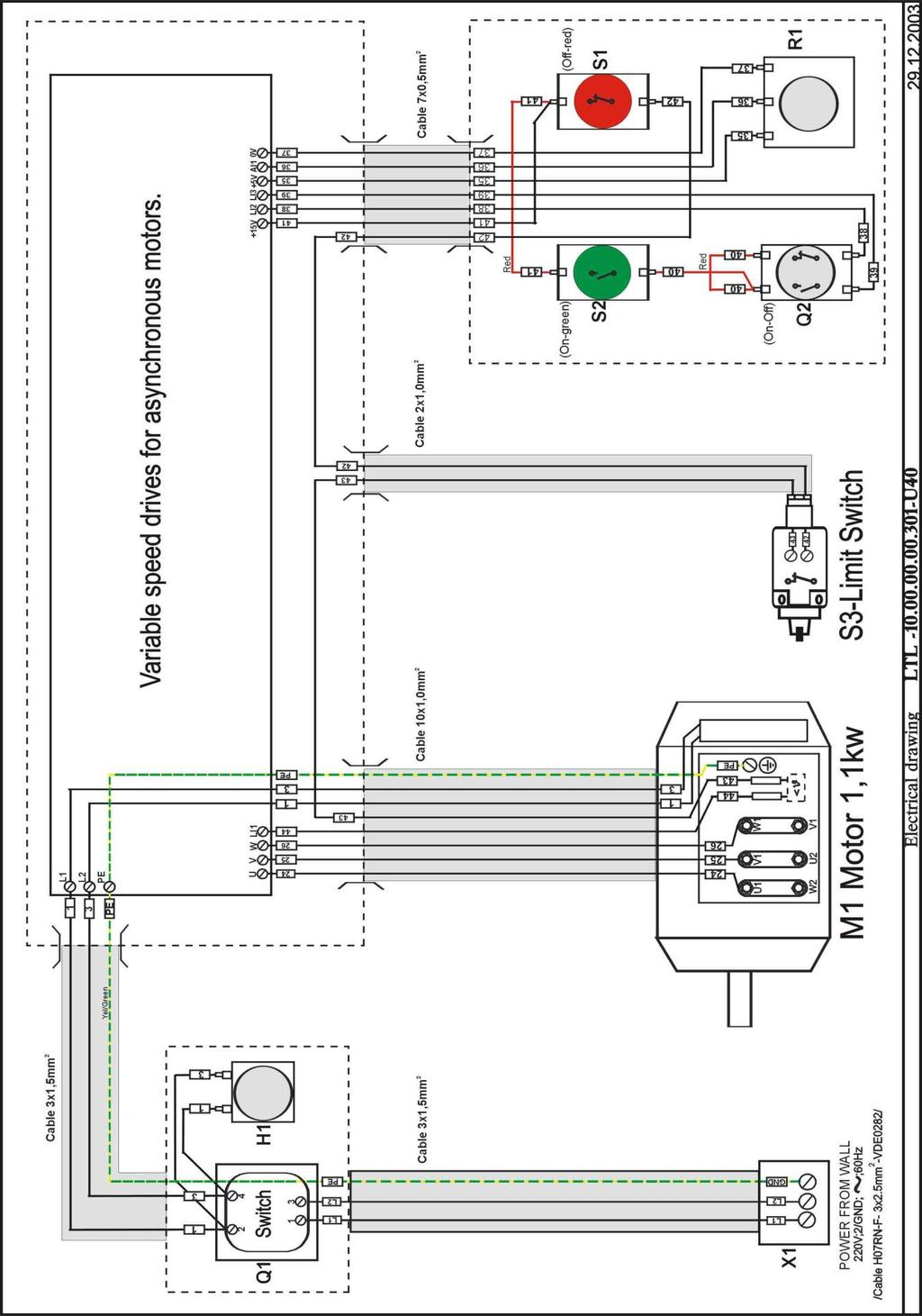
15 Connecting the electrical supply. Earth /Ground wire The machine is supplied with a plug and socket for connection to the electrical supply. No cable is supplied, as this will depend on your installation. Ensure that your electrical supply matches that of your machine. Connect the ground wire [green or yellow green] as shown. Other wires can be connected in either socket. To remove the outer casing of the plug insert a flat screwdriver as indicated Electrical socket on the plug and twist. Note single-phase socket shown. Note. It is recommended that qualified personnel carry out the electrical installation. Ensure that the main supply corresponds with that of the machine. Use wiring suitable for the power and the length of cable that is needed for your installation. On the machine you will see a wire that is yellow and green, this is the ground wire, the other coloured wires are power phase it does not matter what colour combination you use, green/yellow is ground; all other wiring is power (there is no neutral). On single phase the wiring can be interchanged as you wish, it will not Electrical plug affect the rotation of the motor. The direction of rotation of machines with a single-phase supply is predetermined during production. It is recommended that you use a 30-amp mains breaker and number 12 cable for installation up to 15. Installations 15 to 30 should use number 10-gauge cable. Fitting the face plate The face plate screws onto the thread of the headstock spindle. It is locked in position with an allen set screw which when tightened fits into a v groove to ensure that the face plate is securly held in place and will not come loose when the lathe is used in the reverse mode. 15


16 Spindle locking knob unlocked To fit the faceplate, lock the spindle by loosening the spindle locking knob and move towards the rear of the lathe. Rotate the spindle until the locking shaft locates in one of the indexing holes and tighten the knob. Screw the faceplate on to the spindle thread and tighten with the knock out rod as shown. Tighten the allen set screw. Disengage the spindle-locking shaft and tighten the knob to ensure that it will not accidentally engage. To remove the faceplate, reverse the procedure. Spindle locking knob locked Fitting the face plate Fitting the tool rest. Two tool rests are provided. One for center turning and the other for bowl turning. The saddles may come fitted to the bed of the machine, if they are not assembled, assemble as follows. V clamp Lock nut 16


17 1/ Loosen the lock nut. 2/ Assemble the saddle onto the bed of the lathe. Ensure that the V clamp at the front is engaged with the lathe bed. 3/ Engage the V clamp at the rear of the lathe and tighten the lock nut. 4/ You will have to adjust the lock nut so that the clamping handle at the front of the saddle is in a comfortable position when the saddle is locked. 5/ To disassemble reverse the procedure. Note the bowl turning saddle is the larger of the two. Fit the tool rest, adjust to the height that suits the job that you are doing and lock with the clamp handle. Tool rest fitted to lathe Tool rest fitted Under side of tool rest Bowl tool test 17


18 Fitting and removing the tailstock. To remove the tailstock, loosen the clamp handle and slide off the end of the bed. Note the tailstock is made from cast iron and is very heavy. Take care not to drop it or to damage the bed of the lathe when re fitting. Fitting and removing accessories into the tailstock. 1/ Rotate the handle so that the spindle moves forward. Tailstock 2/ Clean the tapered part of the accessory and the tapered hole in the spindle. 3/ Firmly push the accessory into the spindle hole. 4/ Try to twist the accessory. It should be locked in position. To remove the accessory, rotate the spindle handle so that the spindle is moved into the tailstock. The accessory will be ejected from the spindle when the spindle is fully retracted. Underside of tailstock Note hold your hand under the accessory to ensure that the accessory does not fall onto the bed of the lathe when it is ejected. To clamp the tailstock spindle in position tighten the clamp screw on the backside of the tailstock. 18


19 Fitting accessories into the head stock spindle. 1/ Clean the tapered part of the accessory and the tapered hole in Knock out rod the spindle. 3/ Firmly push the accessory into the spindle hole. 4/ Try to twist the accessory. It should be locked in position. Drive centre To remove the accessory insert the knock out rod into the spindle hole from the end of the lathe and give the accessory a sharp knock. Note hold your hand under the accessory to ensure that the accessory does not fall onto the bed of the lathe when it is ejected. Removing and fitting the bed bridge. The chain that the copy saddle uses for controlling the travel along the bed of the lathe will have to be removed. If left attached it will limit the diameter that can be turned. 1/ Move the copy saddle to the tail stock end of the lathe. It should not be in the way when you are turning. 2/ Loosen the panel clamping screws and remove the drive dog clamping nut. 3/ Remove the drive dog and the panel, which has keyhole slots for easy removal. Bridge removed Panel Keyhole slots Drive dog clamping nut Panel and drive dog removed 19


20 4/ Loosen the chain guard plate and remove. The plate has keyhole slots for easy removal. Chain guard plate loose Chain guard plate removed 5/ Loosen the chain by releasing the chain cam and slide the chain block off. 6/ Pull the chain through the headstock and remove it from the drive dog gear. It is not necessary to remove the chain from the copy saddle. 7/ Replace the panel and the drive dog to stop saw dust getting in to the enclosure. Chain cam Chain removed from cam Chain being removed 8/ Leave the chain attached to the copy saddle and it is recommended that the chain is stored in a plastic bag attaches to the copy saddle. This should reduce the possibility of damage and help to keep the chain clean. 9/ To replace the chain reverse the procedure. 20


21 1/ Remove the screws that secure the bridge to the lathe bed and the support beside the headstock. Leaving the top screw on both sides of the bridge in place. 2/ Support the bridge and remove the last two screws. 3/ Gently slide the bridge out. 4/ Protect the bridge from any damage as any burrs or dents may mean that the bridge will not line up with the bed, tool saddles etc. Removing screws Bridge removed 5/ To assemble the bridge reverse the procedure. 6/ The bridge is located on the bed of the lathe with dowel screws, which locate it ensuring that the v slides are aligned. Before finally tightening the screws check that both V slides are in line. Always tighten the screws to the bed of the lathe before tightening the screws by the headstock. Bed extension. The bridge can be used as a short extension for the center lathe. Note. It will not extend the length of the copy attachment. To fit it to the end of the lathe 1/ Attach the bridge with the bolts but do not fully tighten. 2/ Move the tailstock so that it bridges both the lathe bed and the bridge. 3/ Tighten the tail stock clamp handle. This will line up both sets of V s 4/ Tighten the clamp bolts. 5/ Un clamp the tailstock and move onto the bed of the lathe. 6/ Check that the V s are in line and that the tailstock moves over the transition smoothly. 7/ Readjust if required. Bridge fitted as an extension 21

![If you are turning a large bowl blank [48 in diameter] you will not only need to have a low speed but high torque as](/docs-images/79/79570546/images/22-1.jpg "well. In this case the lowest set of pulleys will be required.")


22 Speed selection The lathe is provided with four pulley selections and variable speed. This allows you to select the correct speed for your job and also the correct torque. If you are turning a large bowl blank [48 in diameter] you will not only need to have a low speed but high torque as well. In this case the lowest set of pulleys will be required. The speed range is 0 to 3900 rpm / 0 to 2800 rpm / 0 to 1200 rpm / 0 to 450 rpm The variable speed control is located on the moveable control box. Pulley speed chart To change the pulley speed. 1/ Loosen the locking handle and lift the motor. 2/ Move the drive belt to the required set of pulleys. 3/ lower the motor and tighten the locking handle. Once the pulley Variable speed control knob speed has been selected you can adjust the speed by adjusting the speed control knob on the moveable control box to the required speed. Locking handle Drive belt loose Drive belt tight 22

![The switch has the facility to be padlocked [padlock not provided] in the off position.](/docs-images/79/79570546/images/23-1.jpg "If you are conducting maintenance work or require access to any of the electrical components of the machine you must isolate the machine from the electrical supply by removing the electrical")

23 Electrical controls. The main electrical controls are located on a movable box. Two locations are provided for the box, one on the headstock and the other on the tailstock. The main isolation switch is located on the headstock. Start button 1/ Main isolation switch. This switch isolates the machine electrical system from the incoming electrical supply. The switch has the facility to be padlocked [padlock not provided] in the off position. If you are conducting maintenance work or require access to any of the electrical components of the machine you must isolate the machine from the electrical supply by removing the electrical connector from the machine as well as padlocking the main isolation switch in the off position. 2/ Start button. Pressing the green button starts the lathe motor. Forward / Reverse button Main isolation switch Stop button Variable speed control knob 3/ Stop button / emergency stop button. The red button covers both functions. Once pressed it must be pulled back out before the motor can be started. 4/Forward / reverse switch. The lathe motor can operate in both forward and reverse. Never operate the switch while the motor is moving as it could cause damage to the motor and exerts strain on the machine. If the locking screw has not been tightened in the faceplate or other accessories, it could become detached from the spindle and cause injury. 5/ Speed selection switch. Turning the speed selection switch increases or decreases the speed of the lathe spindle. 6/ Access door safety micro switch. When the door is opened a micro switch isolates the electrical system and stops the motor from operating. If your lathe will not start check that the door is fully closed and that the switch if functioning correctly. Tailstock mounted control box Door safety switch 23
24 Machine test Now is the time to test the machine. 1/ Close the door. If you try to start the machine with the door open the machine will not start, as the safety switch is not made. 2. Check that there are no tools fitted, it is far safer to test the machine with out the tools fitted. 3/ Check that the red emergency /stop switch is in the fully out position. 4/ Check that the machine is clear of all tools and other loose objects. 5/ Check that all the adjusting and locking handles are tight. 6/ Start the lathe by pressing the green start knob. 7/ Now is the time to check that all the safety switches are functioning correctly before you fit any tools 8/ With the machine running, press the red emergency / stop switch. The motor should have the power removed and slow down 9/ With the machine running open the door very slowly until the door switch functions. The motor should have the power removed and slow down. Close the door and wait for the motor to completely stop before you fully open the doors. 10/. If any of the safety switches fail to operate correctly do not use the machine until the fault has been corrected. Indexing head The lathe is provided with an indexing head that can lock the spindle in up to 24 positions. To lock the spindle loosen the indexing pin clamping knob, move towards the indexing plate and rotate the spindle until the relevant hole lines up with the pin. Engage the pin and tighten the knob. The lathe is provided with a spindle clamping block that when activated will ensure that the spindle cannot move. This eliminates any backlash in the system. Various equal positions are achievable by using different combinations of holes as listed below. Divisions Pin numbers 2 = 12,24 3 = 8,16,24 4 = 6,12,18,24 6 = 4,8,12,16,20,24 8 = 3,6,9,12,15,18,21,24 12 = 2,4,6,8,10,12,14,16,18,20,22,24 24 = 1 to 24 It is recommended that the drive belt be removed when using the indexing. Indexing pin loose Indexing pin locked 24


25 Spindle clamp block not engaged Spindle clamp block engaged Tool holder. The tool holder fits to the bed of the lathe as shown and can be positioned at any suitable position. Tool holder 25


26 Optional copy attachment. Copy bracket Attach the left hand and right hand brackets as shown. Do not fully tighten the bolts. Attach the main bar as shown. Main copy bar Copy bracket Measure from the bed to the top of the main bar at both ends and adjust the brackets untill the main bar is parallel. Once parallel tighten the bracket clamp bolts and re check that the main bar is parallel. Adjust if required. Copy follower Assemble the follower as shown. 26

27 Copy cutting tool Assemble the cutting tool as shown There are two methods of adjusting the main bar towards or away from the bed of the lathe. 1/ Rough adjustment is done by loosening the black plastic clamp handle and pushing the bar to the approximate position then. Once in position lock the black plastic handle. 2/ For fine adjustment. Loosen the round clamp knob on top of the main copy bar and adjust the position with the round knob at the end of the bracket. Once in position clamp the top clamp knob. Plastic clamp handle Clamp knob Fine adjusting knob Template / master holder clamp bolt The template holders can be adjusted to any position on the main copy bar by loosening the clamp bolt and sliding the holder to the required position and tightening the clamp bolt. The template holder will accept both templates and round masters. It is strongly recommended that all masters and templates are made from a hard marerial as soft material such as pine will become dammaged by the follower and give poor results. 27

![The main copy bar will have to be set parallel to the axes of the lathe Scribe line here [center line of the spindle].](/docs-images/79/79570546/images/28-1.jpg "The simplest way to achieve this is to place a round piece of wood between centers. Adjust the main copy bar so that the copy follower is running along it. Then cut the wood with the copy attachment.")

28 Master Template Lead in / lead out bracket Clamp screws Fit the template as shown and tighten the clamp screws. Fit a master fit between centers and lock the screw with the lock ring. Once the master or template is in position adjust the lead in / lead out bracket so that the follower has a smooth transition at the ends of the master and the template. The main copy bar will have to be set parallel to the axes of the lathe Scribe line here [center line of the spindle]. The simplest way to achieve this is to place a round piece of wood between centers. Adjust the main copy bar so that the copy follower is running along it. Then cut the wood with the copy attachment. Once the wood has been turned, measure it at both ends and adjust the main bar until the wood being turned is the same dimension at both ends. Once the bar is parallel, scribe [scratch] a line and fill with a permanent marker on both support bracket both sides of the main copy bar support block. You can then use these marks a quick reference whenever you have to set up a new job. Copy saddle control spring Lock nut The follower is controlled by a spring, which is located under the copy saddle at the back of the lathe. The spring pressure can be adjusted and comes factory set to suite most templates and masters. If you require to adjust the spring pressure, loosen both lock nuts, adjust the screw, and re tighten the lock nuts. Screwing the screw out will increase the follower pressure. 28


29 Copy follower To adjust the copy tool, fit the rotating center into the tailstock. Adjust the cutting tip of the tool so that it is level with the point of the rotating center. This will bring the cutting point of the tool onto the centerline of the spindle. The lathe tool holder can be adjusted to suite various diameters of job. Remove the holder fixing screws and reposition the holder to the required position and re clamp in position. Remember to re fit the plastic blanking screws into the holes as this will stop saw dust and dirt getting into the threads. There is a handy reference on the bed of the copy saddle that shows you the range of diameters that can be accommodated for the various positions. Plastic blanking screws Copy tool adjusting knob The knob at the front of the copy saddle controls adjustment of the cutting tool for different diameters. One complete rotation of the knob is The handle on the copy saddle pulls the copy saddle forward and back against the spring and when completely released will allow the copy saddle to move to the position set by the control knob at the front of the copy saddle. Copy tool control handle 29


30 The tool holder is provided with a dust port that you can attach your dust collector to. It is recommended that the minimum air flow of 1000 cubic feet per minute min and a velocity of 65 feet / min [The stronger the dust collector the better] is connected to the dust port. Dust extraction port Copy saddle stop Stops are provided to limit the travel of the copy saddle. They fit onto the bed of the lathe and clamp onto the V s. Care should be taken when moving the saddle along the bed as you could move the stops if you use too much force on the horizontal movement handle. To copy turn. Copy saddle stop There are several of ways to set up for copy turning and with experience, you will decide on the one that suits you. Below is one method that you can use and refine. 1/ Place the template in the U clamps provided, push the template so that the back of the template is flush with the main copy bar and clamp in position. If you are using a master, clamp between centres and lock in position. 2/ Adjust the saddle copy tool to the biggest radius of the job to be copied. You can do this by fitting a rotating centre into the tailstock and bringing the point of the centre in front of the saddle-cutting tool. Measure the distance between the centre point and the cutting point of the tool and adjust using the control knob. 3/ Move the saddle so that the copy follower is in front of the largest diameter of the job. Move to the back of the machine and loosen the two clamp screws on each side of the template holder bar. Slide the bar forward so that the template or master just touches the follower. Using the scribed lines on the bracket and a rule, adjust the main copy bar so that it is equal at both ends and the follower is just touching the largest diameter. 4/ Fit the blank into the lathe and turn, adjusting the control knob so that you cut progressively deeper cuts. Continue until the follower is contacting the template or master along the complete surface. 30
31 5/ Measure the job at both ends and check that it is correct. If you need to adjust the diameter, loosen the template holder bar clamps and adjust with the fine adjustment knobs. Note. When initially setting up, make the job over size as you can always adjust to make it smaller. Note. The copy attachment is controlled by a spring and you will find that it moves into radiuses easier than riding out of radiuses. This is especially true for small radiuses and steep angles. It is recommended that you control the follower with the saddle control handle so that the follower is allowed to move down the radius under the control of the spring and you move the follower out with the control handle. Continue this until you get to one end of the job. Then repeat the procedure from the other end of the job. 31


32 Optional flute cutting attachment. Cutting parallel flutes Remove the relevant set of blanking screws from the saddle and store in a safe place. When you remove the bracket, replace the blanking screws; they will keep the tapped holes clean. Attach the drill / router support bracket to the saddle. Several hole sets can be selected depending on the diameter of the job and the amount of extension that your drill or router has. Attach the drill or router [not provided] and set to the height required for your job. To set the cutter on the center height of the lathe, fit the rotating center into the tailstock and use the point as a reference. You can get different effects on the job by setting the cutter above or below the center height of the lathe. Note. Remove the drive belt from the motor while fluting. If you switch on the motor while the spindle is locked it will stall and it could cause damage. If you are using the spiral indexing system and the motor is switched on it could cause damage to your lathe. Drill fitted for flute cutting Clamping screws You can use the lathe indexing system described earlier in the manual or the spiral indexing system for indexing the spindle when parallel fluting but you can not use the lathe indexing system when spiral fluting. Drill collar clamping screw Use the saddle depth control knob to adjust the depth of the cutter. Use the bed stops to control the length of the flute. Saddle depth control knob 32


33 When cutting spiral flutes you can only use the spiral indexing plate and never try to use the lathe indexing plate, as this will not allow the spindle to rotate. The spiral cutting indexing plate fits into the Morse taper of the headstock. Clean both the spindle hole and the taper shaft of the indexing plate and push into the head stock spindle hole. Test that the plate is fitted correctly and that the taper is holding by trying to twist it. Rear of spiral indexing plate Clamping screw Spiral indexing plate To rotate the indexing plate, remove the clamping screw, rotate the indexing plate to the required hole, and refit the screw. Fit the gear arm as shown. Gear arm Swivel the gear arm down as shown. Gear arm fitted 33


34 Spiral pitch gear chart Decide on the rotation that you require [Left hand or Right hand] and the pitch that you require. Select the gear set that is required for your job from the gear selection on the inside of the door. Note. There is an extra gear in the right hand spiral. This is used to reverse the rotation. Note. The center part of the gear diagram represents the gear arm. Note. Gears B and C fit onto the same shaft, which rotates both gears at the same time. All other gears fit onto a single shaft Note. The top gear numbered 96 [number of teeth] is the gear that is permanently fitted to the lathe spindle and the gear train engages with. Fitting gear Fitting gear Fitting gear Fitting gear 34


35 Note. When assembling the gears they must mesh snugly. If they are too loose there will be play in the system, which could cause chatter and a bad surface finish. If they are too tight the system will be difficult to operate. Rotate the gear arm so that it meshes with the spindle gear and lock in position by tightening the allen screw as shown. Gears engaged with spindle gear Note. Remove the drive belt from the motor when using the spiral cutting attachment. Clamp gear arm To engage the copy saddle with the gears, loosen the clamp screw, rotate the dog so Drive dog not engaged that the drive lines up, and push forward. Lock the clamp nut. When you have finished spiral cutting and have disassembled the gears Drive dog engaged Clamp nut remember to disengage the drive dog and clamp in the disengaged position with the clamp nut. 35


36 Applying the spindle break block will help remove any backlash in the system and improve the finish of the cut. Do not over tighten as the block is meant to exert light pressure. If you over tighten the block you will not be able to move the saddle along the bed and will be putting extra strain on the system. Spindle break Un safe Note. Never place your fingers between the gears as they could crush your finger. Note. It is recommended that you use a router for cutting flutes, as drills are not designed to take side ways pressure and the bearings could ware out with prolonged use. Note. You can use the copy function while cutting flutes both spiral and straight. There are certain limitations when cutting radiuses which will depend on the design of the job. Note. Use the bed stops to control the length of the flute. 36

37 Optional rotating steady 37

38 The rotating steady moves with the copy saddle and supports the job close to the copy cutter. The steady has a cutter that will turn the blank prior to the job moving into the steady. This is a useful function as it allows you to turn none round stock. Assembling the optional rotating steady onto the copy saddle Two additional centres are provided. Both have are extended so that they pass through the rotating rings. Note that one is the drive centre and fits into the headstock spindle and the other rotates and fits into the tailstock. To assemble the rotating steady to the copy saddle The rotating steady must be positioned accurately on the centre line of the lathe spindle both vertically and horizontally. 1/ Fit the base to the copy saddle with the screws provided. Do not fully tighten them until the adjustments are complete 38
39 Turning parallel using the copy saddle. The copy saddle can turn parallel jobs by simply using the slide travel limiter that is a black knob mounted on the front of the saddle. To turn repetitive parallel jobs simply adjust the knob till the sectioned being turned is at the correct diameter. The lathe is now set and will turn jobs to the same diameter repetitively. This is a handy function when turning dowels. Note. Constantly check the finished product for size as the setting could change and you could produce rejects. If you are turning short large diameter jobs you will probably not need to use the rotating steady but if the job is long and thin it will be an advantage. The most useful feature of the rotating steady is its ability to turn square stock round in a single pass. Assembling the pre cutter. A second cutting tool is fitted onto the rotating steady that is used as a pre-cutter. This tool turns the rough stock to a diameter that will fit the bushing that has been selected. It has two bolts/nuts that clamp the housing in position and an adjusting knob. The tool is clamped in position by two Allen screws. Selecting a support bushing in the rotating steady. The rotating steady has a number of bushings that support jobs of various sizes. Select a ring that is the next size up from the biggest diameter of the job. Remove the row of screws and clamp plates that hold the ring in place and then remove the rings. Replace the screws and the clamp plates in the removed ring, you do not want to loose them. Using the pre cutter, turn the stock to a snug fit in the selected bushings. This will support the job and provide a stable work piece for the copy cutter. Assembly and adjusting the pre cutter. 1/ Fit the tool into the holder and clamp in position with the 2 Allen screws. The cutter should protrude 28mm to 30mm [1 1/8 ] 2/ Loosen the pivot bolt, clamp bolt / nut. 3/ Move the tool with the adjusting knob to the approximate position to cut the diameter that you have selected. Ensure that the tool is on the centreline of the job, tighten the clamp bolt and pivot bolt. 4/ Complete a trial cut and measure the diameter. 5/ Adjust the tool to compensate for the error by loosening the clamp bolt and turning the adjusting knob. The top nut will act as a pivot. Once you have completed the adjustment tighten the lower clamp bolt and complete a second trial cut. 6/ Refine the tool position if required. 39


40 Maintenance General. Keep your machine clean. At the end of each day clean the machine. Wood contains moisture and if sawdust or wood chips are not removed they will cause rust. In general we recommend that you only use a Teflon based lubricant on the lathe. Regular oil attracts dust and dirt and the Teflon tends to dry and has fewer tendencies to accumulate dirt and saw dust. The exception is the copy saddle, which is provided with two grease nipples. Any good quality grease can be used and the saddle should be greased every 12 hours of use. After greasing, wipe off any excess grease that is visible. Grease nipples Periodically check that all nuts and bolts are tight. Drive belt The drive belt should last for many years [depending on the usage] but need to be inspected regularly for cracks, cuts and general wear. If damage is found replace the belt. Bearings. All bearings are sealed for life and do not require any maintenance. If a bearing becomes faulty replace it. Rust The lathe is made from steel and cast iron. All none painted surfaces will rust if not protected. It is recommended that applying wax protects them or a Teflon based lubricant Copy saddle chain adjustment. The chain that controls the lateral movement of the saddle comes factory set and should not need adjustment. The chain is provided with an adjustment screw and nut [nut located inside the copy saddle]. If you need to adjust the chain, hold the chain attachment screw steady [it has two flats] so that the chain is not twisted and retention. Chain tensioning screw 40


41 Copy saddle V guide adjustment. Blocks that are on eccentric cams control the clearance between the bed and the copy saddle. By loosening the shaft clamping screw and rotating the eccentric the clearance is adjusted. It is not recommended that the adjustment be changed unless excessive ware has taken place. If adjustment is required loosen the clamp screw and rotate the shaft with an allen key until there is a snug fit between the bed and the copy saddle. The copy saddle should move smoothly with out excessive side ways movement. Copy saddle bed wipers. The copy saddle is provided with nylon wipers that assist in removing any dirt that is on the bed of the lathe when the copy saddle moves along the bed. The pads will need to be removed, cleaned and readjusted periodically. When refitting the wipers ensure a snug fit between the wiper and the bed. They should not be too tight on the bed, as this will cause excessive ware to the wipers. Shaft clamping screw Saddle V guide block Copy saddle bed wipers Tailstock V guide adjustment. V blocks that are on screw threads can be adjusted to change the position that the clamping handle rests in when in the clamped position. To adjust the tailstock to bed loosen the locknut, rotate the screw and re clamp the locknut. Note It is important that both screws are rotated the same amount. If the screws are moved different amounts the adjustable V blocks will not function correctly. Underside of tailstock Tailstock adjusting screw and lock nut 41
42 Troubleshooting. Lathe will not start. 1/ Check that the start switch is being pressed full in. 2/ Check that the red emergency / stop switch is fully out. 3/ Check that the electrical power cord is plugged into the power outlet. 4/ Check that the electrical supply is on [reset the breaker]. 5/ Check that door is closed. 6/ With the power disconnected from the machine, check the wiring to the plug is correct. Check that the rubber insulation is stripped enough and is not causing a bad connection. Check that all the screws are tight. 7/ Test the safety circuit. The machine will not stop. This is a very rare occurrence as the machine is designed to fail-safe. If it should occur and you cannot fix the fault, seek professional assistance. The machine must be disconnected from the power and never run until the fault has been rectified. 1/ Stop switch faulty. Replace the stop switch. 2/ Internal breaker faulty. Replace the breaker. Motor tries to start but will not turn. 1/ With the power disconnected from the machine. Try to turn the spindle by hand. If the spindle will not turn, check the reason for the jamming. 2/ Spindle clamp block left engaged. 3/ Capacitor faulty. Replace the capacitor. 4/ Motor faulty. Replace the motor. 5/ Spindle lock or spiral gears engaged. Disengage. Motor overheats. The motor is designed to run hot, but should it overheat it has an internal thermal overload protector that will shut it down until the motor has cooled and then it will reset automatically. If the motor overheats wait until it has cooled and restart. If the motor shuts down consistently check for the reason. Typical reasons are dull cutting tools, motor cooling fan clogged or faulty, motor-cooling fins clogged, over feeding the job and excessive ambient temperature. Squeaking noise. 1/ Check that the motor cooling fan is not contacting the fan cover. 2/ Check the bearings. 3/ Check the drive belt. Spindle slows down during a cut. 1/ Loose drive belt. Re-tension the belt. 2/ Dull cutting tools. Replace the tool or have it re-sharpened. 3/ Feeding the wood too fast. Slow down the feed rate. 4/ Oil or dirt on the drive belt. Clean or replace the drive belt. Machine vibrates. 1/ Machine not level on the floor. Re-level the machine ensuring that it has no movement. 42
43 2/ Damaged drive belt. Replace the belt. 3/ Job is not balanced. Change to slower speed and or balance the job 4/ Damaged pulley. Replace the pulley. 43
44 44
45 45
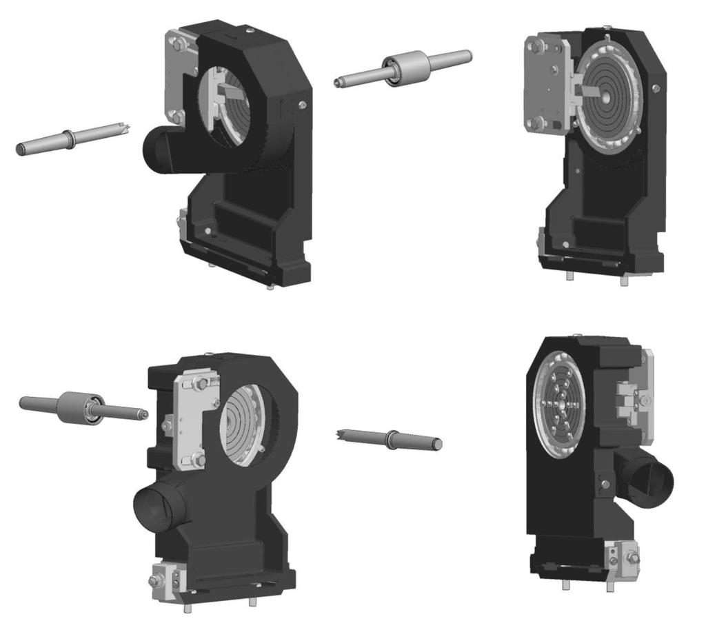
46 LTL WOOD TURNING LATHE 1 LTL LEVELING BOLT 4 2 BDS NUT М LTL TAIL LEG 1 4 BDS SPRING WASHER 2-12Н 12 5 BDS SCREW М12Х LTL BODY 1 7 DIN 1481 SPRING PIN ø8х TL STOPPER ø LTL COVER 1 10 ISO 7380 SCREW М 6Х LTL BRACKET 1 12 BDS SCREW М 6Х LTL HEADSTOCK COLUMN 1 14 LTL FRONT COVER 1 15 LOCKING HANDLE LAGUNA 1 16 BDS SCREW М 6Х BDS WASHER АМ DIN 985 NUT М LTL DOOR 1 20 LTL LOCKING PIN 1 21 LTL KNURLED HANDLE 1 22 LTL UPPER COVER 1 46
47 LTL MAIN DRIVING 1 DIN 7991 SCREW М 6Х LTL CLAMPING RING 1 3 LTL SPINDLE BUSHING 1 4 LTL SPINDLE 1 5 LTL BIG BUSH 1 6 RADIAL BEARING WITH BALLS 6210-ZZ 2 7 LTL MIDDLE BUSH 1 8 LTL NUT М50x BDS KEY 10Х8Х BDS SCREW М 6Х
48 11 BDS SPRING WASHER 2-6Н 1 12 LTL SMALL BUSH 1 13 RADIAL BEARING WITH BALLS 6008-ZZ 2 14 DIN 7991 SCREW М 6Х LTL NUT M30x LTL PULLEY 1 17 LTL INDEXING GEAR WHEEL Z=96; m= VEE BELT XPZ L= BDS BOLT М10Х LTL MOTOR PULLEY 1 21 BDS SCREW М 8Х BDS SPRING WASHER 2-8Н 1 23 LTL WASHER 36х8.5х GN М10-DGN HANDLE М LTL BUSH 1 26 DIN 933 BOLT М10Х BDS WASHER АМ LTL MOTOR ADJUSTING PLATE 1 29 BDS SCREW М10Х BDS NUT М BDS SPRING WASHER 2-10Н 4 32 AR90L- B3 MOTOR 1 33 LTL MOTOR SUPPORT PLATE 1 48
49 LTL TEMPLATE SUPPORT [Optional] 1 CL COTTER 2 2 LTL FRONT BRACKET 1 3 BDS WASHER AM LTL AXIS 2 5 DIN 985 NUT M BDS WASHER AM 8 7 LTL HANDLE 6 8 CL SCREW 2 9 LTL REAR BRACKET 1 10 BDS BOLT М10Х BDS SCREW M 6x BDS SPRING WASHER Н 13 LTL REMOTE STRIP II 1 49
50 14 LTL BEAM 1 15 LTL STUD 2 16 LTL STRIP 2 17 LTL BOTTOM STRIP 4 18 BDS SCREW M 6x CL BOTTOM STRIP 2 20 LTL BASIC STRIP 2 21 LTL SAFETY STRIP 2 22 CL CENTRE 2 23 DIN 134 WASHER M BDS SCREW M 8x BDS SCREW M 6x LTL STRIP 2 27 LTL UPPER STRIP 2 28 BDS BOLT М12x CL UPPER STRIP 2 30 GN М8- HANDLE M8x DGN 31 LTL HANDLE 2 32 LTL REMOTE STRIP I 1 50
PLATINUM SERIES LATHE MANUAL
 PLATINUM SERIES 6-43 LATHE MANUAL LAGUNA TOOLS 2072 Alton Parkway Irvine, California 92606 Ph: 800.234.976 www.lagunatools.com 208, Laguna Tools, Inc. LAGUNA and the LAGUNA Logo are the registered trademarks
Platinum Series 18/47 Lathe Manual
 Platinum Series 18/47 Lathe Manual LAGUNA TOOLS 2072 Alton Parkway Irvine, California 92606 Ph: 800.234.1976 www.lagunatools.com Model Numbers: L A175017 2018, Laguna Tools, Inc. LAGUNA and the LAGUNA
DriftMaster Fence System Manual
 DriftMaster Fence System Manual LAGUNA TOOLS 2072 Alton Parkway Irvine, California 92606 Ph: 800.234.1976 www.lagunatools.com Model Number: ABAND1000-0180 2018, Laguna Tools, Inc. LAGUNA and the LAGUNA
Bat Master CNC Router Manual
 Bat Master CNC Router Manual LAGUNA TOOLS 2072 Alton Parkway Irvine, California 92606 Ph: 800.234.1976 www.lagunatools.com Part No. MCNC Bat Master 2018 Laguna Tools, Inc. All rights reserved. Table of
PLATINUM SERIES TABLESAW W/DOVETAIL MECH LEFT-TILT MANUAL
 PLATINUM SERIES TABLESAW W/DOVETAIL MECH LEFT-TILT MANUAL LAGUNA TOOLS 2072 Alton Parkway Irvine, California 92606 Ph: 800.234.1976 www.lagunatools.com 2018, Laguna Tools, Inc. LAGUNA and the LAGUNA Logo
Revo 10x16 Mini Lathe Manual
 Revo 10x16 Mini Lathe Manual LAGUNA TOOLS 2072 Alton Parkway Irvine, California 92606 Ph: 800.234.1976 www.lagunatools.com Model Numbers: MLA10X16-1_2-0130 2018, Laguna Tools, Inc. LAGUNA and the LAGUNA
MSANOES6X OPERATING MANUAL
 Pro Series Oscillating Edge Sander MSANOES6X89-2-0320 OPERATING MANUAL 2072 Alton Parkway, Irvine, CA 92606 www.lagunatools.com 800.234.1976 Dear Woodworker, Thank you for your purchase and welcome to
LBM 200 Mortiser Manual
 LBM 200 Mortiser Manual LAGUNA TOOLS 2072 Alton Parkway Irvine, California 92606 Ph: 800.234.1976 www.lagunatools.com Model Numbers: MT0LBM200 2018, Laguna Tools, Inc. LAGUNA and the LAGUNA Logo are the
FOURTH-AXIS ATTACHMENT FOR 3-AXIS CNC MACHINES
 FOURTH-AXIS ATTACHMENT FOR 3-AXIS CNC MACHINES LAGUNA TOOLS 2072 Alton Parkway Irvine, California 92606 Ph: 800.234.1976 MCNC SS1 24 x 48-0158 www.lagunatools.com 2018, Laguna Tools, Inc. LAGUNA and the
Dear Woodworker: Thank you for your purchase and welcome to the Laguna Tools group of discriminating woodworkers. I understand that you have a choice
 Platinum Series Tablesaw w/ Dovetail Mech Left-tilt Manual 17101 Murphy Avenue, Irvine, CA 92614 www.lagunatools.com 800.234.1976 MTS0300-0180 1 Table saw Dear Woodworker: Thank you for your purchase and
CNC Lathe 3-Axis Manual
 CNC Lathe 3-Axis Manual LAGUNA TOOLS 2072 Alton Parkway Irvine, California 92606 Ph: 800.234.1976 www.lagunatools.com Model Number: MCNC Lathe 1000-0233 2018, Laguna Tools, Inc. LAGUNA and the LAGUNA Logo
.com. More than a machine. Power your life. Operating Manual
 Operating Manual www.maxnovomachine +86-514-87892928 info@maxnovomachine Dear Customer, Thank you very much for purchasing a product made by MAXNOVO MACHINE. Our machines offer a maximum of quality, technical
Page number Safety Rules 4. Warranty 8. Noise emission 9. Specification sheet 10. Receiving your machine 11. Introduction to your machine 12
 1 8 Table of contents. Page number Safety Rules 4 Warranty 8 Noise emission 9 Specification sheet 10 Receiving your machine 11 Introduction to your machine 12 Parts of the machine 12 What you will receive
T800i Shaper Manual. LAGUNA TOOLS 2072 Alton Parkway Irvine, California Ph: Model Number: MT0T800I
 T800i Shaper Manual LAGUNA TOOLS 2072 Alton Parkway Irvine, California 92606 Ph: 800.234.1976 www.lagunatools.com Model Number: MT0T800I 2018, Laguna Tools, Inc. LAGUNA and the LAGUNA Logo are the registered
VARIABLE SPEED WOOD LATHE
 MODEL MC1100B VARIABLE SPEED WOOD LATHE INSTRUCTION MANUAL Please read and fully understand the instructions in this manual before operation. Keep this manual safe for future reference. Version: 2015.02.02
VARIABLE SPEED WOOD LATHE. Model DB900 INSTRUCTION MANUAL
 VARIABLE SPEED WOOD LATHE Model DB900 INSTRUCTION MANUAL 1007 TABLE OF CONTENTS SECTION...PAGE Technical data.. 1 General safety rules....1-3 Specific safety rules for wood lathe.....3 Electrical information.4
20 x 42 LATHE MANUAL. LAGUNA TOOLS 2072 Alton Parkway Irvine, California Ph:
 20 x 42 LATHE MANUAL LAGUNA TOOLS 2072 Alton Parkway Irvine, California 92606 Ph: 800.234.1976 www.lagunatools.com 2018, Laguna Tools, Inc. LAGUNA and the LAGUNA Logo are the registered trademarks of Laguna
.com. More than a machine. Power your life. Operating Manual
 Operating Manual Dear Customer, Thank you very much for purchasing a product made by MAXNOVO MACHINE. Our machines offer a maximum of quality, technical good solutions and convince by an outstanding price
CL1200 LATHE MT0CL1200 OPERATING MANUAL
 CL1200 LATHE MT0CL1200 OPERATING MANUAL 17101 Murphy Avenue. Irvine, California 92614 www.lagunatools.com 800.234.1976 Dear Woodworker: Thank you for your purchase and welcome to the Laguna Tools group
Owner s Manual Revo 2436 MLAREVO lagunatools.com lagunacleanair.com supermaxtools.com
 Owner s Manual Revo 2436 MLAREVO2436220 lagunatools.com lagunacleanair.com supermaxtools.com Registration To prevent voiding this warranty, all products sold must be registered within thirty (30) days
JOINTERS. MJO MJO phCSA MJO phCSA OPERATION MANUAL
 JOINTERS MJO6405-0800 MJO6012-0800-3phCSA MJO6012-0800-1phCSA OPERATION MANUAL Dear Woodworker, Thank you for your purchase and welcome to the Laguna Tools group of discriminating woodworkers. I understand
13" Moulder Planer Manual
 13" Moulder Planer Manual LAGUNA TOOLS 2072 Alton Parkway Irvine, California 92606 Ph: 800.234.1976 www.lagunatools.com Model Numbers: MPL1301-0130 2018, Laguna Tools, Inc. LAGUNA and the LAGUNA Logo are
12 5-Function Combination Machine Manual
 12 5-Function Combination Machine Manual LAGUNA TOOLS 2072 Alton Parkway Irvine, California 92606 Ph: 800.234.1976 www.lagunatools.com Model Number: MCO8000-0250 2018, Laguna Tools, Inc. LAGUNA and the
24" x 24" OSCILLATING SPINDLE MANUAL
 24" x 24" OSCILLATING SPINDLE MANUAL LAGUNA TOOLS 2072 Alton Parkway Irvine, California 92606 Ph: 800.234.1976 www.lagunatools.com 2018, Laguna Tools, Inc. LAGUNA and the LAGUNA Logo are the registered
Revo & Lathe Manual
 Revo 20 36 & 24 36 Lathe Manual LAGUNA TOOLS 2072 Alton Parkway Irvine, California 92606 Ph: 800.234.1976 www.lagunatools.com Model Numbers: MLA Revo 20-0180 MLA Revo 24-0180 2018, Laguna Tools, Inc. LAGUNA
Horizontal and Vertical. Metal Cutting Band Saw MODEL: BS-115
 Horizontal and Vertical Metal Cutting Band Saw MODEL: BS-5 SAFETY. Know your band saw. Read the operator s Manual carefully. Learn the operations, applications and limitation.. Use recommended accessories.
MODEL H " BYRD SHELIX CUTTERHEAD INSTRUCTIONS
 MODEL H9291 12" BYRD SHELIX CUTTERHEAD INSTRUCTIONS The Model H9291 12" Byrd Shelix cutterhead is designed to replace the straight-knife cutterhead on the Grizzly jointer Model G0609. The total procedure
Inventory (Figure 2)
") MODEL T10127 12" SPIRAL CUTTERHEAD INSTRUCTIONS The Model T10127 indexable insert spiral cutterhead is designed to replace the straightknife cutterhead from the Grizzly jointer Model G0609. The total procedure
MODEL T10127 12" SPIRAL CUTTERHEAD INSTRUCTIONS The Model T10127 indexable insert spiral cutterhead is designed to replace the straightknife cutterhead from the Grizzly jointer Model G0609. The total procedure
EllisSaw.com. EllisSaw.com P.O. Box Verona, WI
 P.O. Box 9019 Verona, WI 9-019 GENERAL OPERATING & SAFETY INSTRUCTIONS * READ INSTRUCTIONS BEFORE USE * CAUTION: Disconnect power supply cord from power source when doing repair work or changing belt.
30DC Speed Lathe Manual
 30DC Speed Lathe Manual The Crozier Model 30DC Speed Lathe is our most popular model. It has many standard features not found on any other machine in its class or price range. Standard Features 3/4 HP
Tech Support: Option 2
 Drift Master Installation Manual Tech Support: 800.332.4094 Option 2 2072 Alton Parkway. Irvine, CA 92606 Website: Lagunatools.com Copyright 2017 Laguna Tools, Inc. Laguna is a registered trademark of
Variable Speed Cast Iron Midi Wood Lathe
 01936 Variable Speed Cast Iron Midi Wood Lathe Please read and fully understand the instructions in this manual before operation. Keep this manual safe for future reference. 1 Technical Data Input voltage
INSTRUCTION MANUAL. Lathe Duplicator MODEL North Glenn Road, Casper, Wyoming woodworker.com
 140-069LatheDuplictr(1/12) 10/30/06 8:20 AM Page 1 INSTRUCTION MANUAL Lathe Duplicator MODEL 140-069 1108 North Glenn Road, Casper, Wyoming 82601 1-800-645-9292 woodworker.com 140-069LatheDuplictr(1/12)
x 43 Wood Lathe
 Please dispose of packaging for the product in a responsible manner. It is suitable for recycling. Help to protect the environment, take the packaging to the local amenity tip and place into the appropriate
TS / TSS Tablesaw Manual
 TS / TSS Tablesaw Manual LAGUNA TOOLS 2072 Alton Parkway Irvine, California 92606 Ph: 800.234.1976 www.lagunatools.com Model Number: MTSS000020 2018, Laguna Tools, Inc. LAGUNA and the LAGUNA Logo are the
5-Function Combination Machine Manual
 5-Function Combination Machine Manual LAGUNA TOOLS 2072 Alton Parkway Irvine, California 92606 Ph: 800.234.1976 www.lagunatools.com Model Number: A175007 2018, Laguna Tools, Inc. LAGUNA and the LAGUNA
x 36 Wood Lathe
 Please dispose of packaging for the product in a responsible manner. It is suitable for recycling. Help to protect the environment, take the packaging to the local amenity tip and place into the appropriate
12mm (Max) 6mm (Max) 82mm (Max) 12mm (Max) 6mm (Max)
 6mm (Max) 82mm (Max) 12mm (Max) 6mm (Max)") 1 1 2 2 3 3 82mm (Max) 12mm (Max) 12mm (Max) 6mm (Max) 4 4 5 6 8 6mm (Max) 0.5 0mm 1 5 6 7 7 8 9 9 A = B 10 11 12 D B 1 13 14 15 0 C A D E 16 17 18 F G D B N H J G I K 19 A 20 G L 21 C K 1mm L M 1mm 22
1 1 2 2 3 3 82mm (Max) 12mm (Max) 12mm (Max) 6mm (Max) 4 4 5 6 8 6mm (Max) 0.5 0mm 1 5 6 7 7 8 9 9 A = B 10 11 12 D B 1 13 14 15 0 C A D E 16 17 18 F G D B N H J G I K 19 A 20 G L 21 C K 1mm L M 1mm 22
Grizzly Drill Press SOP
 Grizzly Drill Press SOP Drill Press is wired to run on 0V. Drill Press has a built in light with a ON/OFF switch. Never hold a workpiece by hand while drilling. Clamp it down or hold it in a vice. Never
HOLE CUTTER SHARPENER ASSEMBLY & SERVICE MANUAL
 HOLE CUTTER SHARPENER ASSEMBLY & SERVICE MANUAL WARNING You must thoroughly read and understand this manual before operating the equipment, paying particular attention to the Warning & Safety instructions.
REVO & Lathe Manual Model MLA REVO Model MLA REVO
 REVO 20-36 & 24-36 Lathe Manual Model MLA REVO 20-0180 Model MLA REVO 24-0180 LAGUNA TOOLS 17101 Murphy Ave. Irvine, California 92614 Ph: 800.234.1976 www.lagunatools.com Part No. MLA REVO 20-0180 Part
MI MI OPERATING MANUAL
 MODEL NO.: MI-76100 MI-76150 OPERATING MANUAL RULES for SAFE OPERATION MAGNUM INDUSTRIAL MI-76100 and MI 76150 DRILL PRESSES To help ensure safe operation, please take a moment to learn the how to operate
Bed Extension Kit 16 Instructions
 The premier source of tooling, parts, and accessories for bench top machinists. Bed Extension Kit 16 Instructions This kit converts a 7 10, 7 12, and 7 14 mini lathe manufactured by SIEG (including those
LEG CURL IP-S1315 INSTALLATION INSTRUCTIONS
 LEG CURL IP-S35 INSTALLATION INSTRUCTIONS Copyright 2009. Star Trac by Unisen, Inc. All rights reserved, including those to reproduce this book or parts thereof in any form without first obtaining written
TB & SB Series Drill Presses
 TB & SB Series Drill Presses OWNERS MANUAL BENCH AND FLOOR DRILL PRESS TB-16 Series & SB-16-25-32-Series FOR YOUR OWN SAFETY AND OPTIMUM OPERATION READ INSTRUCTION MANUAL BEFORE OPERATING DRILL PRESS RETAIN
WARNING! Read and understand the entire instruction manual before attempting set-up or operation of this machine!
 ! WARNING! Read and understand the entire instruction manual before attempting set-up or operation of this machine! 1. This machine is designed and intended for use by properly trained and experienced
ELECTRIC SLIP ROLL MACHINE. Model: ESR-1300X2.5/ESR-1300X4.5 ESR-1550X3.5/ESR-1580X2.0
 ELECTRIC SLIP ROLL MACHINE Model: ESR-1300X2.5/ESR-1300X4.5 ESR-1550X3.5/ESR-1580X2.0 Operation Manual Table of contents I MAIN SPECIFICATION...2 II SAFETY INSTRUCTIONS.. 2 III OPERATION INSTRUCTIONS..4
Quick Set Dovetail Jig
 Quick Set Dovetail Jig FOR HELP OR ADVISE ON THIS PRODUCT PLEASE CALL OUR CUSTOMER SERVICE HELP LINE : 01509 500359 THE MANUFACTURER RESERVES THE RIGHT TO ALTER THE DESIGN OR SPECIFICATION TO THIS PRODUCT
Jointer/ Planer Combination Machine Manual
 Jointer/ Planer Combination Machine Manual LAGUNA TOOLS 2072 Alton Parkway Irvine, California 92606 Ph: 800.234.1976 www.lagunatools.com Model Number: MJOPL104200 2018, Laguna Tools, Inc. LAGUNA and the
MODEL T " HELICAL CUTTERHEAD INSTALLATION INSTRUCTIONS
 MODEL T27696 12" HELICAL CUTTERHEAD INSTALLATION INSTRUCTIONS For questions or help with this product contact Tech Support at (570) 546-9663 or techsupport@grizzly.com Introduction The Model T27696 indexable
GENERAL OPERATIONAL PRECAUTIONS PRECAUTIONS ON USING CUT-OFF MACHINE
 GENERAL OPERATIONAL PRECAUTIONS WARNING! When using electric tools, basic safety precautions should always be followed to reduce the risk of fire, electric shock and personal injury, including the following.
Model: SCD430 SCD640. Installation & Operation Guide P/N SCD640-95
 Model: SCD430 SCD640 Installation & Operation Guide P/N SCD640-95 Model SCD430 and SCD640 Kurt has two Self-Centering vises, a four-inch jaw width (SCD430) and a six-inch jaw width (SCD640). Jaw opening
Due to possible damage in shipping, the vertical stop assembly has been removed from this machine.
 Due to possible damage in shipping, the vertical stop assembly has been removed from this machine. To assemble, insert the threaded rod through the shroud opening in the top of the machine. Start the four
ATD AMP Variable Speed Reciprocating Saw Owner s Manual
 ATD-10535 7 AMP Variable Speed Reciprocating Saw Owner s Manual Manufactured in China To ATD Tools, Inc. Specifications TECHNICAL SPECIFICATIONS Voltage: 120V Frequency: 60Hz Power input: 7 Amps No load
3-1/4 HP VARIABLE SPEED PLUNGE ROUTER
 IMPORTANT INFORMATION 2-YEAR LIMITED WARRANTY FOR THIS PLUNGE ROUTER KING CANADA TOOLS OFFERS A 2-YEAR LIMITED WARANTY FOR NON-COMMERCIAL USE. 3-1/4 HP VARIABLE SPEED PLUNGE ROUTER PROOF OF PURCHASE Please
CHAINSAW SHARPENER MODEL: ECSS-1
 CHAINSAW SHARPENER MODEL: ECSS-1 Part No: 3402075 ASSEMBLY & INSTRUCTION MANUAL LS0409 INTRODUCTION Thank you for purchasing this CLARKE product Before attempting to use the product, it is essential that
Operating, Servicing, and Safety Manual Model " Foot Shear CAUTION: Read and Understand
 Operating, Servicing, and Safety Manual Model 3000 52" Foot Shear CAUTION: Read and Understand These Operating, Servicing, and Safety Instructions, Before Using This Machine. SAFETY The purpose of the
MODEL SETUP & OPERATION MANUAL DOVETAIL JIG FEATURES SPECIFICATIONS
 SETUP & OPERATION MANUAL FEATURES Male and female dovetail joints are cut simultaneously, to ensure perfectly matched dovetail joints. Side stops provided, allow repeated precise dovetail joint cutting
MODEL 83 Pail Handler
 MORSE MFG. CO., INC. 727 West Manlius Street P.O. Box 518 East Syracuse, NY 13057-0518 Phone: 315-437-8475 Fax: 315-437-1029 Email: service@morsemfgco.com Website: www.morsemfgco.com COPYRIGHT 2005 MORSE
MODEL SETUP & OPERATION MANUAL DOVETAIL JIG FEATURES
 SETUP & OPERATION MANUAL FEATURES New clamping system for greater accuracy. Lockable template height for a stable platform for the router. Cuts precision matching dovetails with the same accuracy found
Tapping Screw (W/Flange) 46 Cord Armor 47 Tube (D) 48 Cord. 45 Cord Clip. Tapping Screw (W/Flange) 10 Gear Cover Ass'y. 12 Socket (B) Ass'y
 46 Cord Armor 47 Tube (D) 48 Cord. 45 Cord Clip. Tapping Screw (W/Flange) 10 Gear Cover Ass'y. 12 Socket (B) Ass'y") W8VB The exploded assembly drawing should be used only for authoized service center. W8VB Item No. Part time 1 Magnetic Hex. Socket 2 Sub Stopper 3 O-Ring (S-16) 4 Locator (A) 5 Lock Sleeve (A) 6 O-Ring
W8VB The exploded assembly drawing should be used only for authoized service center. W8VB Item No. Part time 1 Magnetic Hex. Socket 2 Sub Stopper 3 O-Ring (S-16) 4 Locator (A) 5 Lock Sleeve (A) 6 O-Ring
 GENERAL OPERATIONAL PRECAUTIONS WARNING! When using electric tools, basic safety precautions should always be followed to reduce the risk of fire, electric shock and personal injury, including the following.
Lassco Spinnit EBM-2.1 Paper Drill
 Lassco Spinnit EBM-2.1 Paper Drill User's Manual Provided By http://www.mybinding.com http://www.mybindingblog.com Serial Number: Date of Purchase: Dealer: Address: Before operating this equipment, please
30AUTO Speed Lathe Manual
 30AUTO Speed Lathe Manual Standard Features 3/4 HP Motor Air-Collet Closure 1800 RPM, Single Speed Electric Brake Cast Housing 5C Collets 3 Phase / 240 Volts DESCRIPTION: The Crozier Model 30AUTO Automotive
INSTRUCTION BOOK AND PARTS LIST
 Rag Cutter MODEL WE WARNING This machine is equipped with a very sharp knife. Keep hands, arms, and hair away from the knife area at all times. Misuse of this machine or failure to follow all safety instructions
SERVICE MANUAL PARTS LIST MODEL: NH40
 SERVICE MANUAL & PARTS LIST MODEL: NH40 CONTENTS What to do when... 1-3 SERVICE ACCESS Face Cover... 4 Bed Cover... 5 Free-arm Cover... 6 Front Cover... 7 Rear Cover... 8 MECHANICAL ADJUSTMENT Presser
24 GA. PITTS ROLLFORMER
 1 TIN KNOCKER 24 GA. PITTS ROLLFORMER INSTRUCTIONS & PARTS DIAGRAM Shown with Stand and Optional Flanging Attachment Rev. 092606 TAAG MACHINERY CO. (Master Distributor) 1257-B Activity Dr. Vista, CA 92081
TurncrafterPlus. Variable Speed Mini Wood Lathe. User s Manual #TCLPLUS PRODUCT NO.
 TurncrafterPlus Variable Speed Mini Wood Lathe PRODUCT NO. #TCLPLUS User s Manual SPECIFICATIONS OF TURNCRAFTER PLUS MINI LATHE Model number:..............................................#tclplus Motor:......................................0V
Removing and Replacing the Y-truck
 Service Documentation Removing and Replacing the Y-truck To remove and replace the Y-truck you will need the following tools: 4mm Allen wrench 12mm stamped flat wrench #2 Phillips screwdriver (magnetic
SERIES I MILLING MACHINES
 INSTALLATION, OPERATION, MAINTENANCE, AND PARTS LIST SERIES I MILLING MACHINES TP5260 Revised: August 29, 2005 Manual No. M-450 Litho in U.S.A. Part No. M -0009500-0450 June, 2003 MAINTENANCE PROCEDURES
Record the serial number and date of purchase on your parts list for future reference.
 Jointer Model: 0-0 Parts List Record the serial number and date of purchase on your parts list for future reference. Serial number: Date of purchase: Part # 0-0PL For more information: www.rikontools.com
SECTION 9: PARTS G7945/G7946
 SECTION 9: PARTS G7945/G7946 Main Parts 22 53 25 26 31 139 32 32-1 60 38 59 38-1 119 35 37 31 38-3 124 125 45A-2 45A-4 45A-1 31 60 45A-3V2 120 121 62 28 28-1 28 27 34 50 51 39 41 126 137 36 46 40 63 33
GEARED HEAD DRILL / MILL MACHINE INSTRUCTION MANUAL
 www.industrialtool.com.au GEARED HEAD DRILL / MILL MACHINE INSTRUCTION MANUAL READ CAREFULLY AND UNDERSTAND THESE INSTRUCTIONS BEFORE USE. LIMITED WARRANTY Industrial Tool & Machinery Sales (hereinafter
SECTION 9: PARTS. Headstock A 126A 127A-1 REF PART # DESCRIPTION REF PART # DESCRIPTION
 SECTION 9: PARTS Headstock 120 121 113 115 112 111 110 109 108 105 106 107 135 101 119A 121 120 118 114 115 107 106 104 123 122 118 114 126A 105 126 103 102 126B 127A-1 131 127A 124 133 134 126C 129 130
GENERAL OPERATIONAL PRECAUTIONS PRECAUTIONS ON USING DISC GRINDER
 GENERAL OPERATIONAL PRECAUTIONS WARNING! When using electric tools, basic safety precautions should always be followed to reduce the risk of fire, electric shock and personal injury, including the following.
RPS /02 Effective for models with serial numbers beginning with "G".
 Instruction Sheet B2000 Cyclone Bender RPS-0097 0/02 Effective for models with serial numbers beginning with "G". IMPORTANT RECEIVING INSTRUCTIONS Visually inspect all components for shipping damage. If
The MUELLER method of making a main to service connection using the MUELLER E-5 Small Drilling Machine. Hand or power. kpa/34.
 MUELLER SMALL DRILLING MACHINES 2.1 Shaded area indicates change Rev. 9-09 MUELLER Co. manufactures several different small drilling machines for drilling holes from 7/16" to 2" in all types of pipe. Machines
8" JOINTER MANUAL. LAGUNA TOOLS 2072 Alton Parkway Irvine, California Ph:
 8" JOINTER MANUAL LAGUNA TOOLS 2072 Alton Parkway Irvine, California 92606 Ph: 800.234.1976 www.lagunatools.com 2018, Laguna Tools, Inc. LAGUNA and the LAGUNA Logo are the registered trademarks of Laguna
MODEL T " SPIRAL CUTTERHEAD INSTALLATION INSTRUCTIONS
 MODEL T27449 8" SPIRAL CUTTERHEAD INSTALLATION INSTRUCTIONS The Model T27449 indexable insert spiral cutterhead is designed to replace the straightknife cutterhead on the Grizzly jointer Model G0490W/G0490XW
Cut-True 16M Manual Paper Cutter
 Cut-True 16M Manual Paper Cutter 2/2013 OPERATOR MANUAL FIRST EDITION TABLE OF CONTENTS TOPIC PAGE Specifications 1 Safety Guidelines 1 Assembly 2 Overview 3 Description of Equipment Parts 3-4 Operation
CONTENTS PRECAUTIONS BEFORE STARTING OPERATION PREPARATION FOR OPERATION CAUTIONS ON USE OPERATION
 CONTENTS PRECAUTIONS BEFORE STARTING OPERATION ------------------------------------- 1 PREPARATION FOR OPERATION 1. Adjustment of needle bar stop position ---------------------------------------------------------
Operating Instructions and Parts Manual SLT-1100 Jumbo Scissor Lift Table
 Operating Instructions and Parts Manual SLT-1100 Jumbo Scissor Lift Table JET 427 New Sanford Road LaVergne, Tennessee 37086 Part No. M-140780 Ph.: 800-274-6848 Revision B1 05/2014 www.jettools.com Copyright
OPERATORS MANUAL. Band Saw by. Model SFI-60. (877) East (800) West
 East (800) West") OPERATORS MANUAL Band Saw by INVICTA Model SFI-60 INVICTA USA (877) 308-6423 - East (800) 499-4682 - West English Version General Instructions Thank you for purchasing this quality machine from INVICTA.
OPERATORS MANUAL Band Saw by INVICTA Model SFI-60 INVICTA USA (877) 308-6423 - East (800) 499-4682 - West English Version General Instructions Thank you for purchasing this quality machine from INVICTA.
16 Planer with ShearTec II Manual
 16 Planer with ShearTec II Manual LAGUNA TOOLS 2072 Alton Parkway Irvine, California 92606 Ph: 800.234.1976 www.lagunatools.com Model Numbers: MPLAN1510-0120 2018, Laguna Tools, Inc. LAGUNA and the LAGUNA
Cam Handle Service Guide
 Cam Handle Service Guide Page 2. Introduction Page 3. Troubleshooting guide Page 4-5. Adjusting the clamp force Page 6-7. Disassembling, greasing and replacing components Page 8-9. Replacing the post bearings
Operating Instructions
 Operating Instructions Holding the material against the angle gauge slide it into the forming head. Be sure that the material remains against the gauge until work is finished. NOTE: This machine will handle
Inventory (Figure 2)
") MODEL T10130/T10126 6" & 8" SPIRAL CUTTERHEAD INSTRUCTIONS The Model T10126/T10130 indexable insert spiral cutterheads are designed to replace straightknife cutterheads from the Grizzly jointer Models
MODEL T10130/T10126 6" & 8" SPIRAL CUTTERHEAD INSTRUCTIONS The Model T10126/T10130 indexable insert spiral cutterheads are designed to replace straightknife cutterheads from the Grizzly jointer Models
SERVICE MANUAL AND PARTSLIST
 SERVICE MANUAL AND PARTSLIST Next 20 CONTENTS WHAT TO DO WHEN... 1~3 SERVICE ACCESS FACE COVER... 4 TOP COVER... 4 BASE COVER... 5 REAR COVER... 6 FRONT COVER... 7 MECHANICAL ADJUSTMENT NEEDLE THREAD TENSION...
Cyclone Upcut Cut off saw
 Cyclone Upcut Cut off saw Operation manual WARNING The operator must thoroughly read and understand this manual before operating the cut off saw or starting any servicing. All safety and warning instructions
ABM International, Inc.
 ABM International, Inc. Lightning Stitch required 1 1.0: Parts List head and motor assembly (Qty. 1) Reel stand (Qty. 1) Needle bar frame clamp (Qty. 1) Motor drive (Qty. 1) 2 Cable harness with bracket
ABM International, Inc. Navigator Assembly Manual
 ABM International, Inc. 1 1.0: Parts List Tablet (Qty. 1) Tablet mount (Qty. 1) NOTE: Mount may appear and operate different then image below Control Box (Qty. 1) Motor Power Supply (Qty. 1) 2 X-axis motor
RTI TECHNOLOGIES, INC.
 RTI TECHNOLOGIES, INC. BRC500 & BRC550 Arbor/Spindle Mechanism Adjustment & Service Technical Instructions The arbor/spindle mechanism of the BRC500/550 is designed to be robust for long life. Occasionally
SAVE THIS FOR FUTURE REFERENCE THIS PRODUCT IS FOR PROFESSIONAL LABORATORY USE ONLY USER'S MANUAL
 DENTAL, INC. TECHNICAL BULLETIN G801-022510 5860 FLYNN CREEK ROAD READ ALL INSTRUCTIONS P.O. BOX 106 BEFORE PROCEEDING COMPTCHE, CALIFORNIA, U.S.A. 95427-0106 SAVE THIS FOR FUTURE REFERENCE www.wellsdental.com
TUCANA-02 P PORTABLE END MILLING MACHINE USER S MANUAL
 TUCANA-02 P PORTABLE END MILLING MACHINE USER S MANUAL 1 CONTENTS Page 1. General Information 3 1.1. Introduction 3 1.2. Manufacturer 3 2. Machine s Description and Purpose of Use 3 2.1. Machine s description
OPERATION & MAINTENANCE MANUAL
 OPERATION & MAINTENANCE MANUAL AUTOMATIC PECAN CRACKER Food Processing Equipment and Machinery Specializing in the Pecan Industry Mailing: PO Box 817, Mansfield, Louisiana 71052 Located: 280 Independence
Swing over bed 17.3" Center height 8.6" Swing over cross slide 9.4" Distance between centers 39.3" Width of bed 11.8"
 MODEL KL1640 PLUS Swing over bed 17.3" Center height 8.6" Swing over cross slide 9.4" Distance between centers 39.3" Width of bed 11.8" Spindle speed L:50-355 rpm, H:352-2500 rpm Spindle number 2 Spindle
Ellis Drill Press Model 9400
 Ellis Drill Press Model 9400 Instruction Manual POWER FEED DRILL PRESS Infinitely Variable Speed Model 9400 Operation Manual February 17, 2006 CONTENTS Page Number Preface 2 Installation Instruction 2
OPERATION, PARTS & MAINTENANCE MANUAL MODELS HB73-16 HB97-18 HB97-16 HB97-12 HB HB HB HB145-18
 OPERATION, PARTS & MAINTENANCE MANUAL MODELS HB73-16 HB97-18 HB97-16 HB97-12 HB121-18 HB121-16 HB121-14 HB145-18 Proudly Made in the USA 2 3 4 FOREWORD This manual has been prepared for the owner and operators
Trade of Toolmaking Module 2: Turning Unit 1: Machine Controls and Operations Phase 2
 Trade of Toolmaking Module 2: Turning Unit 1: Machine Controls and Operations Phase 2 Published by SOLAS 2014 Unit 1 1 Table of Contents Document Release History... 3 Unit Objective... 4 Introduction...
The MUELLER method of making a main to service connection using the MUELLER E-5 Small Drilling Machine. The main is drilled out under pressure.
 MUELLER SMALL DRILLING MACHINES 2.1 Rev. 9-09 MUELLER Co. manufactures several different small drilling machines for drilling holes from 7/16" to 2" in all types of pipe. Machines are available in hand