Making a Pan Brake "Folder with fingers" for home
|
|
|
- Joanna Jackson
- 6 years ago
- Views:
Transcription

1 Making a Pan Brake "Folder with fingers" for home By Simso Taken from: Okay, just a quick overview of what were dealing with here. Grahame posted up recently a topic about handiest tool you ve made for metalwork, I posted a pic of my panbrake folder with fingers and through Pm s from people wanting more info, I have decided to start a thread with step by step guide to how to make one. This will take a sheet of steel up to 600mm wide and bend 1.6mm mild steel nice and sharply. If you want to be able to bend thicker steel sharply then you can and Ill point out which bits need to be beefeir as I go along. For the purpose of this exercise Im actually going to help a local mate build one and Ill organise photos on the way, so that way you can see whats actually involved in them. Theres a bit of welding a bit of milling and a bit of lathe work, if you don t have access to a mill, lathe or a 20 and 25mm drill bit then I recommend maybe getting the bits laser cut out, Ill give you a rough costing of how much these cost as well. Total cost of unit in materials 2 years ago anyway wont go over 80 bucks, if you get bits laser or plasma cut then maybe 150 all up, not bad when you consider a commercial unit of this strength and quality will cost you around What can I bend with this unit, well I use this for making my own tool boxes at home and I restore old cars,so as you can imagine for restoration it is absolutely unbelievable. I made one for a mate who works in the panel and paint business, he uses this unit every day just to make the rust replacement bits for the cars, and were talking from mazdas to mercedes. A lot of the shape to these bits is purely asthetical, I made my very first unit out of square edges act, worked great looked like crap. But it worked, its your call I lost all the computer files a while back hard drive crash, I have my original hand drawn ones and some printed cad drawings, so I may take a while with some of the photos pics as Ive got to redraw them On my pictures youll see the following notes 125,35 This is a cad co-ordinate, or for your ruler from the corner of your paper 125mm across and 35mm up is the point at reference D/T=Drill and Tap D = Drill R = Radius

2 Step 1, you require 2 units of this item as they are the ends to your bed. If you get your measurements out between the two units, it will still work but it will stiffen the mechanism, and promote wear. Don't forget to Drill and tap the two holes from above, so that way you can bolt your bed down later. You can square all slopes if you want to there just there for aesthetics. If you wish to get these laser cut, it'll cost you about 18 bucks each. Plasma cut even cheaper again. Ill attach a photo of a completed item as well, Have fun now


3 Step 2. Foot end piece, nothing complicated here, its just 2 lumps of steel that s going to be welded in step 3 to the end pieces from step 1, all it does is provide some rigidity for the end pieces and a means of clamping them down to a bench hence the holes. If you want it can be just a flat piece of steel with no holes etc.


4


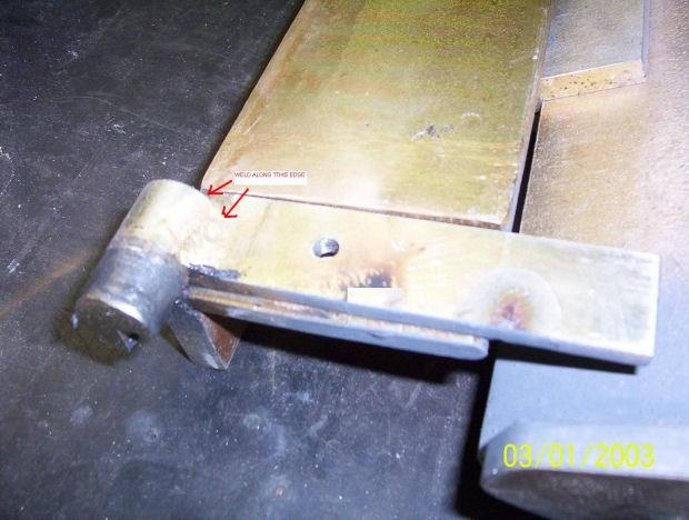
5 Step 3. Okay all you ve got to do here is simply weld item 2 onto the bottom of the end piece run a couple of stitch welds on the inside and tack it 3 places outside, grind the outside ones flush for aesthetics. Make sure the pieces face inwwads respective of which end they are on eg left and right. If you cant weld the item then drill 2 holes 8mm in size up through the end piece foot and tap 2 m8 holes in the bottom of the end pieces and simply bolt them together Step 4. Flat Bed piece,okay this piece is simply flat bar 684mm long by 110mm wide with a material thickness of 10mm. The two end holes on both sides are 8mm and allow the bed to be bolted down with m8 bolts to the end pieces, thereby creating the folder base frame. The first notch you see in the corner allows the bed to sit around the end piece, with this in mind if you cant get a piece of steel 110 wide but in fact wider say up to 150mm then its not a problem youll just have to do a similar notch on the back edge for whatever deviation you go by. Eg 150mm requires a rear notch of 40mm and so forth. Okay the second notch on the front you see is for clearance of the lifting assy pivot point, have a look at the completed picture to get a better understanding if required.


6 Through the center there are 3 holes 8mm in dia these are for the attachment of the brace in step 5 for rigidity, obviously you will have to countersink the tops so that way the heads of your bolts are not sitting proud, if your happy welding the underneath brace then don t bother drilling these holes, they are there solely for the drilling and tapping method of assy. Okay that s pretty much it for this step, have fun now


7 Step 5. Flat Bed brace piece, this is solely to add ridgitiy to the bed so that way when you bend say a 1.6mm piece of steel the bed base wont bow on you, trust me it will if you don t fit it. Okay its flat steel again 10mm thick, 652mm long and 25mm high, you can use up to 50mm wide for extra ridgitity or if you cant get it for some reason in the 25mm range

8 Step 6. Okay lets fit the two pieces from step 4 and step 5. The flat bed is simply bolted down using two m8 bolts on the end pieces from step 3. That s it. Now place the flat bed brace bar underneath the flat bed and clamp it along the center line 19mm back from the front edge, if you drilled the 3 center holes from above you'll see the steel dead smack underneath you. Have a look on the end pieces as well it should cover the 8mm holes you drilled on both sides. Okay drill and tap the flat bar from the end pieces first. Now bolt them up with m8 bolts. You can remove your clamps. If you drilled the three center holes through your flat bed then now continue these three holes into the flat bed brace using a 6.8mm drill and then tap them m8, dont forget to countersink the holes on the flat bed as required by whatever fastener heads your using, its got to be a flush surface remember. If you didn t drill the three holes then stitch weld from underneath the flat bed brace onto the flat bed


9


10 Step 7. Lifting assy handle and locating guides are simply made out of 20mm round stock. The handle is 400mm long and 20mm round, it can be longer if you wish or shorter. I mill both sides of one end down by 3mm per side with a milled length of 55mm, you could also easily file this shape in as well, its not critical, the flat surfaces are a means of allowing the handle to sit flush with the lifting arm. There are two 8mm holes and these are center located from the end 10mm and 40mm.


11 These are here so you can bolt the item to the lifting arm, if your happy once again welding the item in place then disregard drilling the holes and just weld the handle in place when the time comes The locating guides are included into this step because they are 20mm round as well, you need qty 2 and they each have a length of 35mm, find the end center of each piece and mark it out so you have 4 perfect quarters. Remove one complete quarter for the full length, file it, mill it, it doesn t matter just remove one quarter. After you ve done this test there fit against the end pieces, these go into the 20mm holes at the front, sand grind ect to make a nice smooth fit, your goal is to have them turn smoothly in the end pieces, and yes you do use grease when assembly comes, so you can test them with grease as well Okay that s this step completed

12 Step 8 Lifting assy brace piece, this is exactly the same piece as you made for the bed brace, its flat steel 10mm thick, 652mm long and 25mm high its purpose is to extend the 10mm edge you have on your lifting assy and help assist in the fold. For those that don t know trying to bend a piece of steel with a 10mm edge is really horrible, you have this sheet of steel hanging out and swaying everywhere, you also start getting creases in your steel ect when you try to bend it, hence the requirement of this piece, it extends that 10mm edge and turns it into a 35mm edge, If you want you can use a wider piece than the 25mm bar, but the wider you go the more it intrudes into working space around the folder.


13 Step 9. Really easy one, you need two of these, this is a flat piece of 5mm thick steel 110mm long and 25mm wide. It has a 5mm by 5mm notch in one corner and this is here to allow you to put a blob of weld on it later. The hole is central and 40mm away from the edge, its an m8 size drilled and tapped. The purpose of this piece is to allow the lifting assy to be moved closer or further away from the bed assy. The closer you get the sharper the bend radius on the item you fold, the further away the rounder the bend radius you get on the folded job. That s a s difficult as it gets


14

15 Step 10 Okay this is the last step for component making for the the lift assy, in the next step we will put all these bits together.this item is a piece of 10mm flat bar 650mm long and 75mm wide, if you want wider like a 100mm then thats fine as well but you cant vary the 650mm length There are two slots, one on each end, drill these with a 10mm drill at the co-ordinates ive written and then simply file the gap or mill between the holes. The two holes in the centre are drilled and tapped for an m8 thread, this is were you will bolt up your handle from the earlier step. You have to mill both 75mm width ends as shown in the drawing down to a thickness of approx 5mm and a width of 25mm. The adjustment slides you made before in step 9 need to sit neatly and flush at these points. If you want to this can be laser cut as well for about 15 bucks.


16 Step 11 Okay lets put the bits together, fist well take your adjustment arms and your pivot units and weld them together. Basically take the adjustment arm end with the notch slit into it, place this into the 45 degreed groove of the pivot units and overhang the edge with the cutout, you need to make a left and right unit so the cut outs overhang on the inside edge, now just weld the item into place on the outer edge of the pivot unit, use the attached photo for reference if needed. Next bolt these two slides onto the main fold arm this is the unit with the 25mm milled edgee. Now bolt the handle to the back side And lastlty the brace, butt this against the top front edge to extend the 10mm width to now 35mm width, you can either weld it into place or if you so choose drill and tap the unit in place, your call. The lift mechanism is now complete, undo the bed base plate from the ends slide this unit into the front 20mm holes use a bit of grease and then bolt the base bed back on. Hope it all makes sense


17


18


19

20 Step 12 Okay there are two of these units they allow the clamping assy to move up and down and backwards and forwards. For info when you bend a piece of steel you adjust the clamping fingers back from the main edge of the bed by the thickness of the steel your bending, if you don t move them back then when you raise your lifting assy youll snap of the front edge of your fingers. Mmm not good that s for sure. Okay the drawing is for aesthetics, you can use just a piece of square if you want. 10mm thick, 145 mm long and 50mm high. These can be laser cut for about 5.50 each.


21

22 Step 13 This is simply a piece of unequal angle 65mm by 50mm x 6mm thick with a length of 675mm It holds the fingers and supplys the ridgity to hold the sheet solid and square during the fold. If your going to bend thicker steel than 1.6mm then this needs to be 10mm thick or greater, same rule applies if you wish to make the bed wider than the 600mm unit. You need to notch the ends on the 50mm length in to a depth of 15mm with a width of 15mm this is to allow clearance on your base bed end pieces, if you want for aesthetics you can machine the 50mm length to a total thickness of 35mm for the entire length, your choice. The cad picture shows the unit with notched ends, my photo shows where I milled it for the full length.


23


24 Step 14. This unit allows the end pieces of your clamping assy to be fastened to the bed through the 20mm hole, it also allows the clamping assy to move forwards and backwards by simply turning the hex part of this assembly with a shiftter. Okay 2 pieces of 25-35mm hex bar 22mm in length with one side turned down to approx 20mm by 10mm length. I say approx because this needs to fit into the clamping assy end piece which you ve already made, so if they have a slightly larger or smaller hole then you can compensate for this now. You also need to drill a 8mm hole through the entire piece, off centre by about 5mm, its not critical just so long as you don t drill through the outer wall.
25 Step 15 This is probably the hardest for most people to do, my recommendations get someone that has a mill to do it for you, you can do these by hand by scribing a line in the waste areas clamping it into a vise and draw filing the items. Basically it s a piece of 10mm thick steel by whatever widths you want with a machined height of 91mm or thereabouts make it a 100 if you want, just make sure there all the same. The top angle is 40 degrees but you can vary this up to 45 degrees if you want as well. The machined section on the bottom is 30mm long by 3mm deep this allows a solid hard face for clamping onto your cross brace. The other relief is simply a key way setup for the clamp brace to lock into, have a look at the pic for a better explanation. The hole is 9mm wide so that way an m8 bolt fits in loosely, if you make 100mm wide units youll want 2 bolt holes 200mm wide units 3 and so on. That s it


26 Step 16 Just a bit of angle line here cut down and a hole tapped to allow the finger to tighten into, pic saids it all. Next step we will assemble this part of the unit which only leaves one stage to go and that s the locking stage

27 Step 17 Lets assemble the clamping assy. Firstly attach the clamping assy ends onto the base frame end pieces by bolting the pivot units into place, the clamping assy ends sit external to the base ends. Rotate the pivot units so they move the clamping assy end pieces as far forward as possible. Now bolt them down tight so they don t move. Take two fingers and fasten them onto your main arm one at each end. Place the main bar between the clamping assy ends and rest the fingers on the base bed. Lift and prop up the back of the main arm until the fingers are sitting dead flush this is important, once there sitting nice and squarely tack weld the main arm to the clamping assy ends. Raise the assembled unit up and down a few times to make sure it is square ect and it sits flush and if it does then fully weld the ends into place. That s this step finished You can remove and paint the item if you want as theres no more work required on this part


28


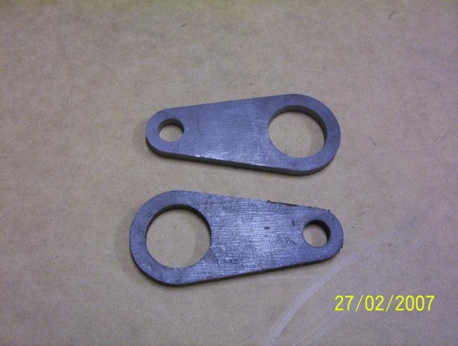
29 Step 18. Locking Assy canter lever. Okay you need two of these items, they are 155mm long by 70mm wide by 10mm thick, the shape I have given is purely aesthetic, you can use a flat piece with square edges. Laser cut they cost about 8 bucks each. One end has a 47mm hole and the other end a 20mm hole, distance between hole centers is 100mm


30

31 Step 19. This is word for word the same as step 14, so when you make the two for step 14 make 4 so that way this steps done as well, but lets say it again anyway. Okay 2 pieces of 25-35mm hex bar 22mm in length with one side turned down to approx 20mm by 10mm length. I say approx because this needs to fit into the locking assy end piece which you ve already made, so if they have a slightly larger or smaller hole then you can compensate for this now. You also need to drill a 8mm hole through the entire piece, off centre by about 5mm, its not critical just so long as you don t drill through the outer wall.

32 Step 20. This is the pivoter units, it allows the clamping assy to be locked by overcentring the clamping arm. It s two simple pieces of round turned down to fit into the canter levers with a shoulder still present and a 20mm hole drilled of centre and a small m8 hole drilled and tapped for handle attachment later on. Use the drawing supplied for locations and measurement points


33 Step 21. Easiest piece to make, it connects the two pivoters together and allows them to turn in unison to each other. It s a 20mm round bar 730mm long with m8 threads drilled and tapped into each end for bolting the handle on later. I recommend whilst you ve got this out of the unit, scribe a line through the centre of both ends in the same plane as each other, this will help in jigging the pivoters squarely when we fit them in the final assembly. Okay one handle and 2 bushes and were finished


34 Step 22 Okay there are two of these, they are simply a plastic bush that pops into the 25mm hole in the end pieces from stage 1. It allows the crossbar from this stage to rotate smoothly. The shoulder can be any dia or thickness but I went with 5mm because that gave a bit of strength to the bushing, I would not go greater than 10mm because it may bind the canter levers up during there movement. The center outer bit is 25mm but machine to fit your end pieces and the bore is 20mm but once again machine to suit your crossbar.


35 Step 23. Last piece and a nice easy one to do as well. Its just a piece of 20mm round or box tube ect about 450mm long doesn t really matter what length and a piece of 25mm angle line welded on the bottom with two holes through it for attaching onto the pivoter unit. That s it no more parts to make, just assemble this stage and wolla one folder completed, with many years of use to come


36 Step 24. Okay lets assemble the locking mechanism, which also completes the final step in the folder. Insert the plastic bushes from step 22 into the end pieces of your base bed these are the ones you made in step 1. Insert the locking assembly cross shaft though both bushes this is the item from step 21. Now assemble the pivoter item from step 20 into the canter levers from step 18. Push the canter lever over the top of the shaft protruding from your plastic bushes until the end of the cross arm is flush with the pivoter. Now we have to lock the pivoter and cross arm together, I hope you marked a line on each end like I said to in step 21, you have a choice now you can weld the two items together that is the cross arm and pivoter but it meand you will not be able to disassemble the unit again. I like to scotch key the two items together. That is drill a hole between the two pieces and tap a thread and insert a bolt in, havce alook at one of the phots Ive attacehed for clarification. The important thing here is to ensure that both pivoters are in alignment with each other and locked to the shaft. Okay pop in your pivot units from step 19 into the top of your canter levers and bolt them onto the clamping assy ends from step 12. Bolt your handle onto one of the pivoter ends left or right it doesn t matter its universal. And your finished. Yayyyyy Now have a play The rear pivot units move your bed back and forth and the front pivot units vary the clamping force on the job, you want to set this so that way with a piece of 1.6mm steel it overcentre locks, youll see what I mean when you do it. Enjoy for many years to come


37


38
39
INSTALLING YOUR NEW SPRING LIFT ARM KIT
 INSTALLING YOUR NEW SPRING LIFT ARM KIT 1. Measure the distance that the roof is to be raised. [If your lift system is completely non-functional, you will need to calculate or estimate this distance as
Precision Steel Car s 100 T Steel Coil Car
 Precision Steel Car s 100 T Steel Coil Car Precision Steel Car www.precisionsteelcar.com info@precisionsteelcar.com Paul Vernon: (513) 571-5739 Revised 4/30/2009 Contents of Kit Main Tube Side Frame 2
1949 to 1954 Chevrolet Dual Master Cylinder Conversion
 1949 to 1954 Chevrolet Dual Master Cylinder Conversion This document is a one stop shop to getting your brake system updated on your old Chevy. Whether you re going with a disc conversion or just sticking
Coil Winder Instructions.
 Page Coil Winder Instructions. Before we can build our wind turbine there are a few tools we need to make. We ll need to make moulds for the magnet rotors and the stator, and we need to make a coil winder.
Sheet Metal Brake Plans for a 6' Sheet Metal Brake
 Sheet Metal Brake Plans for a 6' Sheet Metal Brake,1752'8&7,21 Thank you for purchasing the sheet metal brake plans. The plans include a complete list of material needed and easy to follow steps to build
Hinge Mortising Jig. One of the make it or break it parts of building a. 6 ShopNotes No. 74
 Hinge Mortising Jig A Mortise for a Hinge. Quick, clean, and accurate that s the only way to describe the mortise you get with a trim router and this hinge mortising jig. One of the make it or break it
How To Build A Tube Bender by Terry Tasky
 How To Build A Tube Bender by Terry Tasky I would like to thank the good people at Blind Chicken Racing for supplying the basics to make this bender. I have taken their project a step further and have
Technicians of Terror. This is the air valve we make to use with our air
 These are pictures of our scissor prop. Technicians of Terror http://www.halloweenfear.com/scissorprop.html props. This is the air valve we make to use with our air This pictures the duel door closer cylinders
ASSEMBLY INSTRUCTIONS FOR MAR-K BEDSIDES AND GM FLUSH TAILGATE WITH HANDLE
 ASSEMBLY INSTRUCTIONS FOR MAR-K BEDSIDES AND 41-53 GM FLUSH TAILGATE WITH HANDLE Build the box assembly according to the MAR-K assembly instructions. When installing the tailgate and latching mechanisms
Ratcheting and Angled Leg Vises. Ratcheting Parallel Guide
 Ratcheting and Angled Leg Vises Ratcheting Parallel Guide In Scott Landis s The Work Bench Book there is a drawing of a ratchet mechanism for a parallel guide. It was one of those little tidbits I tend
Rorty No.2 Tube Bender.
 Copyright. This entire Manual is copyrighted to Rorty Design, with all rights reserved. No part may be transferred or copied by any means whatsoever, without the express written permission of Rorty Design.
Assembly Instructions 10 X 10 Aluminum Roof Support
 Assembly Instructions 10 X 10 Aluminum Roof Support Aluminum Roof Support Bolt Package 16-5/16 X 2 ¼ SS Bolt 24-5/16 X 1 SS Bolt 40-5/16 SS Nylon Lock Nuts 16-5/16 SS Flat Washers 28-4 ½ Wood Screws 36-1
7x --Tailstock Cam Lock
 7x --Tailstock Cam Lock By Magic Brian magicbrian40@yahoo.com Probably the most pleasing mod to have, but often not done through lack of milling facility s This version does NOT require a mill. MATERIALS
Tail Vise. Installation Instructions. (revised 10/11/2017)
") Tail Vise Installation Instructions (revised 10/11/2017) Lie-Nielsen Tail Vise Instructions Table of Contents page About Your Tail Vise 3 Parts List 4 step 1. Prepare Your Bench Top 5 step 2. Prepare the
Tail Vise Installation Instructions (revised 10/11/2017) Lie-Nielsen Tail Vise Instructions Table of Contents page About Your Tail Vise 3 Parts List 4 step 1. Prepare Your Bench Top 5 step 2. Prepare the
TOOL LIST FOR TAILGATE HIDDEN LATCH & LINK ASSY FOR FORD FLARESIDE TRUCKS
 TOOL LIST FOR TAILGATE HIDDEN LATCH & LINK ASSY FOR 53-87 FORD FLARESIDE TRUCKS Vise Grip Clamps C-clamps Sharpie Marker Ball Peen Hammer Center Punch 3/8 or 1/2 Drill 5/32, 7/32, 9/32, and 3/8 Drill Bits
Shoulder Plane. dovetailed. fine tools. Make an heirloom tool and learn the secret to creating double dovetails in metal it s easier than you think.
 fine tools dovetailed Shoulder Plane Make an heirloom tool and learn the secret to creating double dovetails in metal it s easier than you think. I ve always been fascinated by old, metal hand planes.
Tortoise Switch Machines, Mounted Horizontally
 Tortoise Switch Machines, Mounted Horizontally by David King Have you ever used the Tortoise Switch Machines manufactured by Circuitron. These are a wonderful stall motor slow motion switch machine that
Assembly Instructions 10 X 10 Aluminum Frame Building
 Assembly Instructions 10 X 10 Aluminum Frame Building 27 97 9 8 47 36 74 52 10 10 X 10 Square Building W/ Dome Includes: The Steel Entry Door with a Dead Bolt Lock assembly and Aluminum Door Frame. Metal
Metal Shapers Forums and Tech Rodding Roundtable Home Forums Events Members Webring Tech Merchandise Contact Chat Services Links Want Ads Advertising
 Metal Shapers Forums and Tech Home Forums Members Webring Tech Contact Chat Services On the following pages your will find detailed instructions on the parts needed and assembly instructions for a 12"
Norman's Grizzly G0602 Reverse Tumbler Plans
 Norman's Grizzly G0602 Reverse Tumbler Plans Pictures taken by Norman Author Norman here is the photos of the change gears for the G0602 lathe. reverse turning to the right or for left hand threads netural
AMETAL SHAPER is indispensable for certain METAL SHAPER FOR YOUR SHOP. By S. S. Miner
 METAL SHAPER FOR YOUR SHOP By S. S. Miner AMETAL SHAPER is indispensable for certain machining operations where flat surfaces must be produced within very close limits, such as machining flats on castings,
Lada Niva Front Crossmember Lift By Simon Allen
 Lada Niva Front Crossmember Lift By Simon Allen This is to document how I did my front cross member lift for the Niva, as a few people have asked me now. This is just a guide, and already there have been
Complete Dovetail Jig Instructions
 Complete Dovetail Jig Instructions 15 18 4 3 1 12 13 8 19 17 16 6 14 5 9 11 10 2 9 PARTS LIST - Complete Dovetail Jig Introduction Your new dovetail jig will cut Full Through Dovetails and three varieties
Chain Drive Vise. Installation Instructions. (revised 05/04/2016)
") Chain Drive Vise Installation Instructions (revised 05/04/2016) Lie-Nielsen Chain Drive Vise Instructions Table of Contents page About Your Chain Drive Vise 3 Parts List 4 Exploded Parts Diagram 5 step
Chain Drive Vise Installation Instructions (revised 05/04/2016) Lie-Nielsen Chain Drive Vise Instructions Table of Contents page About Your Chain Drive Vise 3 Parts List 4 Exploded Parts Diagram 5 step
INSTALLATION INSTRUCTIONS CHEVY C-10 INDEPENDENT FRONT SUSPENSION
 INSTALLATION INSTRUCTIONS 73-87 CHEVY C-10 INDEPENDENT FRONT SUSPENSION Please read these instructions completely before starting your installation. Assemble suspension on vehicle before powder-coating
STANDARD CANOPY WORK REPORT B-1
 STANDARD CANOPY WORK REPORT B-1 No. Check Parts / Tools Qty _ Canopy Lock 1 [ ] 6E2-3 Canopy Hinge Block 1 2 [ ] 6E4-5 Canopy Side Frame 2 2 [ ] 6E2-1 Canopy Lock Assembly 1L + 1R 3 [ ] 6E2-4 Rear Lock
Sunrise Deck Assembly Instructions for Kingston Left
 Sunrise Deck Assembly Instructions for Kingston Left It s easiest to build the deck frame first like it will be lying on its back and then after all 4 legs and horizontals are in place, tip the deck toward
Lumber Smith. Assembly Manual. If you are having problems assembling the saw and need assistance, please contact us at:
 Lumber Smith Assembly Manual If you are having problems assembling the saw and need assistance, please contact us at: 804-577-7398 info@lumbersmith.com 1 Step 1 Safety Carefully read the Owners Manual.
Stage 2: Preparing the door (read in conjunction with Hole Drilling Options on back of Template).
.") There are three stages to fitting the CL100 mortise case: Stage 1: Marking out the position of the lock. Stage 2: Preparing the door by mortising and drilling holes. Stage 3: Fitting lock, door furniture,
There are three stages to fitting the CL100 mortise case: Stage 1: Marking out the position of the lock. Stage 2: Preparing the door by mortising and drilling holes. Stage 3: Fitting lock, door furniture,
P.O. Box 8400 Green Bay, WI (920)
") P.O. Box 8400 Green Bay, WI 54308-8400 (920) 468-2165 Change Notice No. 112 Implemented By: KI-Pembroke Notification By: Scott Vissers Date: 03/15/10 Component Product Title: Series XXI Lateral Filing
P.O. Box 8400 Green Bay, WI 54308-8400 (920) 468-2165 Change Notice No. 112 Implemented By: KI-Pembroke Notification By: Scott Vissers Date: 03/15/10 Component Product Title: Series XXI Lateral Filing
Tools: Sharpie, Square, Vise, Hack saw, Ruler, Punch, Hammer, File. 2. Cut the stock Place stock in vise and cut with hack saw
 Purpose: MAKE CATAPULT ARM Step 1 Tools: Sharpie, Square, Vise, Hack saw, Ruler, Punch, Hammer, File Materials: Flat aluminum ½ inch stock (see picture below) Gloves required 1. Pick up the aluminum ½
Build a Drill Press Vise
 Youth Explore Trades Skills Introduction This activity plan will develop the student s machining and metalworking skills as they fabricate a multi-piece steel vise. The project will encompass basic lathe
Continue gluing the remaining top parts ensuring the angled piece is glued well. Set aside and let dry. See photo below
 Radiator rev 1.1 The SE5a s radiator is one of the most recognized radiators in WW1. It is one of the components that defines the SE5a. The original SE5a has seen multiple radiator designs used during
Thor Audi A4/S4 Skid Plate Installation Instructions
 Thor Audi A4/S4 Skid Plate Installation Instructions Parts List: 1 Aluminum Skid Plate 2 Aluminum Side Wings 10 10mm Flat Washers 3 8mm Flat Washers 3 8mm Speed Clips 2 10x40mm Bolts 3 8x35mm Bolts 2 Rivet-nuts
Travis Bishop. Submitted to: Dr. John Davis. Date: 3 December Course: ETME 310 Section: 004. Lab Topic: Milling Project (Vise)
") Travis Bishop Submitted to: Dr. John Davis Date: 3 December 2012 Course: ETME 310 Section: 004 Lab Topic: Milling Project (Vise) Introduction: Purpose of Experiment: This experiment was conducted to teach
Travis Bishop Submitted to: Dr. John Davis Date: 3 December 2012 Course: ETME 310 Section: 004 Lab Topic: Milling Project (Vise) Introduction: Purpose of Experiment: This experiment was conducted to teach
END FRAMES. End frames built using pressure treated 2x4 (1 1/2" x 3 1/2") 36" 34" 7/16" pilot hole. 5 1/2" x 1/2" lag bolt 8" wheel 23"
 36 34 7/16 pilot hole. 5 1/2 x 1/2 lag bolt 8 wheel 23") END FRAMES End frames built using pressure treated 2x4 (1 1/2" x 3 1/2") 23" 17 1/2" (B) (B) Measure from the bottom of your stone to 1" below the lip to get your measurement. 17 1/2"(B) 36" 34" 1/2" flat
END FRAMES End frames built using pressure treated 2x4 (1 1/2" x 3 1/2") 23" 17 1/2" (B) (B) Measure from the bottom of your stone to 1" below the lip to get your measurement. 17 1/2"(B) 36" 34" 1/2" flat
Building a vertical wobbler
 Building a vertical wobbler I wanted to build a simple steam engine that would also run on compressed air. At Chris Heapy s website (http://easyweb.easynet.co.uk) I found drawings of a small double acting
INSTALLATION INSTRUCTIONS
 INSTALLATION INSTRUCTIONS PARTS REQUIRED Single QuickStand Lite Parts A (1) Lower Arm A B C D B (1) Upper Arm C (1) Base D (1) Base Plate E (1) M8 Dynamic Arm Long F (1) Clamp Bracket G H (1) VESA Plate
FABA. Installation Instructions. Conductor Bar System. Publication #FABA-03 3/1/04 Part Number: Copyright 2004 Electromotive Systems
 FABA Conductor Bar System Installation Instructions Publication #FABA-03 3/1/04 Part Number: 005-1062 Copyright 2004 Electromotive Systems 1S 100 Z Installation Instructions Contents: Basic Diagram - -
GlideRite Retractable Cover System For HotSpring & Tiger River Spas (except Classic & pre-2000 Landmark Spas)
") List of Contents Quantity Description 12 #10 x 1 ½ Flat Head Phillips Screw (see pg. 2) 2 #10 x ½ Pan Head Phillips Screw (see pg. 2) 8 ¼ x 2 ½ Lag Bolt (see pg. 2) 7 ¼ 20 x 5 / 8 Hex Head Bolt (see pg.
List of Contents Quantity Description 12 #10 x 1 ½ Flat Head Phillips Screw (see pg. 2) 2 #10 x ½ Pan Head Phillips Screw (see pg. 2) 8 ¼ x 2 ½ Lag Bolt (see pg. 2) 7 ¼ 20 x 5 / 8 Hex Head Bolt (see pg.
Chain Drive Vise. Installation Instructions. (revised 11/29/2018)
") Chain Drive Vise Installation Instructions (revised 11/29/2018) Lie-Nielsen Chain Drive Vise Instructions Table of Contents page About Your Chain Drive Vise 3 Parts List 4 Exploded Parts Diagram 5 step
Chain Drive Vise Installation Instructions (revised 11/29/2018) Lie-Nielsen Chain Drive Vise Instructions Table of Contents page About Your Chain Drive Vise 3 Parts List 4 Exploded Parts Diagram 5 step
Building Rudy Kouhoupt s Walking-Beam Engine
 Building Rudy Kouhoupt s Walking-Beam Engine Some time ago I came across a copy of Rudy Kouhoupt s article: "Build this Walking-Beam Engine" (Popular Mechanics August 1969), and decided to try and make
An Adjustable Threading Feed Attachment for a Lathe Without Metric Threading Capability, by Ted Clarke
 An Adjustable Threading Feed Attachment for a Lathe Without Metric Threading Capability by Ted Clarke Metric pitch threads, with the exception of the Royal Microscopical Society (RMS) 36 threads per inch
 For Wallbed models: KING SIZE INSTRUCTION BOOKLET #C1 Watch step by step installation instructions at: https://www.wallbedsbywilding.com/wallbed-installation-studio-series/ WARNING! ALL MURPHY/WALLBED
Clock 35 - Toyland. Construction instructions for Clock 35
 This clock has been designed for children, it is a stand-alone unit and can be positioned on a shelf or cabinet out of the reach of very young hands who may be tempted to touch. The clock is shown in two
Reversing Gear. Shay Reversing Gear
 Shay Nelson Riedel Nelson@NelsonsLocomotive.com Initial: 9/23/03 Last Revised: 06/05/2004 The reversing gear is another one of those pieces I've been putting off. The reason for the postponement was that
Side Winder R o u t e r L i f t.
 Woodpeckers PRECISION WOODWORKING TOOLS Side Winder R o u t e r L i f t. INSTALLATION INSTRUCTIONS The wrench handle must be pointing left in order to fully insert or remove it. Lift Wrench Once fully
MINI-LATHE QUICK CHANGE TOOL POST
 MINI-LATHE QUICK CHANGE TOOL POST Cutting and assembly details Machinists should familiarize themselves with the contents of this section before jumping in to the drawings. Many details are described here
Installation Instructions for FC2 & FC15 Forward Controls for the Super Magna
 Installation Instructions for FC2 & FC15 Forward Controls for the Super Magna It is highly recommended that you use a thread lock compound such as Loctite brand on all threads to keep them from vibrating
Removing and Replacing the Y-truck
 Service Documentation Removing and Replacing the Y-truck To remove and replace the Y-truck you will need the following tools: 4mm Allen wrench 12mm stamped flat wrench #2 Phillips screwdriver (magnetic
6625 WEST WILSHIRE BLVD. OKLAHOMA CITY, OK (405) FAX (405)
 FAX (405)") INSTALLATION INSTRUCTIONS FOR BEDSIDE INNER REPAIR PANELS 67-72 GM FLEETSIDES This instruction illustrates the removal and replacement of the often rusted and damaged lower inner flanges on the 1967-1972
INSTALLATION INSTRUCTIONS FOR BEDSIDE INNER REPAIR PANELS 67-72 GM FLEETSIDES This instruction illustrates the removal and replacement of the often rusted and damaged lower inner flanges on the 1967-1972
Don't Be A Cart-Aleck
 Don't Be A Cart-Aleck Indulge your resourcefulness by building a classic gocart! (If you have a favourite youngster, you should probably know how to build a go-cart.) Materials: Tools Four wheels with
LocoGear. Technical Bulletin - 14 November 28, 2003 Copyright 2003 by LocoGear LIVE STEAM CASTINGS. Tech Bulletin - 14
 LIVE STEAM CASTINGS LocoGear Tech Bulletin - 14 John D.L. Johnson 3879 Woods Walk Blvd Lake Worth, FL 33467-2359 jjohnson@locogear.com www.locogear.com Technical Bulletin - 14 November 28, 2003 Copyright
GlideRite Retractable Cover System For Hot Spot Spas (SE & SLX only)
") List of Contents Quantity Description 12 #10 x 1 ½ Flat Head Phillips Screw (see pg. 2) 2 #10 x ½ Pan Head Phillips Screw (see pg. 2) 8 ¼ x 2 ½ Lag Bolt (see pg. 2) 7 ¼ 20 x 5 / 8 Hex Head Bolt (see pg.
List of Contents Quantity Description 12 #10 x 1 ½ Flat Head Phillips Screw (see pg. 2) 2 #10 x ½ Pan Head Phillips Screw (see pg. 2) 8 ¼ x 2 ½ Lag Bolt (see pg. 2) 7 ¼ 20 x 5 / 8 Hex Head Bolt (see pg.
INTRODUCTION. EqunioxRoof.com. Pro Tip
 INSTALLATION MANUAL INTRODUCTION The Equinox Louvered Roof System is designed to be installed in an aluminum frame. All these sections are 1/8" thick extruded aluminum. All engineering for this system
Hardware and Components:
 Hardware and Components: (A) 4X 5/16 x 1 Carriage Bolt (B) 2X 5/16 x 2-1/4 Carriage Bolt (C) 2X 5/16 x 3-1/4 Hex Bolt (D) 2X 5/16 x 3/4 Hex Bolt (E) 2X 5/16 x 1-1/4 Hex Bolt (F) 5/16 x 2-1/4 Hex Bolt (G)
Basic steps to time the Gammill quilting machine s rotary sewing hook
 Basic steps to time the Gammill quilting machine s rotary sewing hook 1.) Turn the machine off and unplug it. 2.) With the needle bar in the raised position, remove the bobbin and bobbin case. 3.) Remove
WPS crew Doors Installation instructions
 WPS-132-133 crew Doors Installation instructions ORDER OF INSTALLATION FOR A COMPLETE ENCLOSURE OF A CREW WPS (Weather Protection System) IS AS FOLLOWS: 1. Heater 2. Rear Thresholds - Right Hand & Left
F i t t i n g t h e N e w L a n d i n g G e a r t o Y o u r S k y J i b V 1
 F i t t i n g t h e N e w L a n d i n g G e a r t o Y o u r S k y J i b V 1 1 P a r t s L i s t : S t a n d a r d L a n d i n g G e a r U p g r a d e Product Code Parts + Spares Product Code Parts + Spares
Clayton Off Road COR COR COR
 Clayton Off Road COR-4806011 COR-4806021 COR-4806031 JEEP GRAND CHEROKEE WJ LONG ARM UPGRADE KITS (1999-2004 WJ) NOTES: This product requires general welding, fabrication and automotive mechanic skills.
With a little time and effort, you can increase the performance of your engine by going from THIS.
 How-To Modify The V6 & V8 Throttle Body This modifying procedure is for the 5.2 and 5.9 V8 and the 3.9 V6 TB''s. With a little time and effort, you can increase the performance of your engine by going
Plans. Easy-to-Build Full-size Deluxe Murphy Bed Plan. For more plans, tools and hardware visit rockler.com
 Easy-to-Build Full-size Deluxe Murphy Bed Plan Build a full-size Deluxe Murphy Bed complete with decorative molding and matching side cabinets! Plans For more plans, tools and hardware visit rockler.com
Building a Universal Panorama Head
 Building a Universal Panorama Head Fig 1: Universal Panohead This paper describes the process of building a universal panorama bracket. The intention is to describe the process I used rather than provide
Oxford Stalls Installation Instructions
 Oxford Stalls Installation Instructions RAMM Horse Fencing and Stalls 13150 Airport Hwy. Swanton, OH 43558-9615 1-800-434-8456 Rev. 8/15/17 Before You Start Typical stall sizes are 10 x 10, 12 x 12 or
FLOW HIVE ASSEMBLY GUIDE. If we look after the bees they will look after us, and the honey really is an amazing bonus. Flow Hive Hybrid 3 Frame
 AUSTRALIAN MADE If we look after the bees they will look after us, and the honey really is an amazing bonus. FLOW HIVE ASSEMBLY GUIDE Flow Hive Hybrid 3 Frame Read all instructions first. If you are unfamiliar
Model Assembly & Operating Instructions
 30 SHEAR BRAKE ROLL Model 05907 Assembly & Operating Instructions Diagrams within this manual may not be drawn proportionally. Due to continuing improvements, actual product may differ slightly from the
Tool & Cutter Grinder
 Tool & Cutter Grinder The Bonelle Tool and Cutter grinder (based on prof. Chaddock s Quorn) can be used to grind most kind of tools from lathe tools to end-mills and reamers. I have been grinding my end-mills
Making a 1911 frame from scratch the easy way. 7 parts make up the frame in a 1911 pistol,
 Making a 1911 frame from scratch the easy way. 7 parts make up the frame in a 1911 pistol, The rails and fire control block- needs to be as strong as a standard one piece frame The grip sides (2 off) -
The Queen Quilter Professional Quilters Kit Frame
 The Queen Quilter Professional Quilters Kit Frame Assembly Instructions Table of Contents: Before you begin......................... Pg. 2 Wood parts............................. Pg. 3 Hardware..............................
A Quick-Change Gearbox For The 7x Minilathe
 A Quick-Change Gearbox For The 7x Minilathe Richard Hagenbuch 10 August 2002 This article describes how to a build a quick-change gearbox for your 7X minilathe. I'll describe one that I built as a prototype
DTU Animal Cart Programme
 DTU Animal Cart Programme TECHNICAL 25 LIGHT STEEL AND WOOD DONKEY CART RELEASE Development Technology Unit, Department of Engineering, University of Warwick, Coventry, CV4 7AL UK, tel: +44 (0)203 523523
woodworkersjournal.com MATERIAL LIST
 MATERIAL LIST T x W x L 1 Legs (2) 1 1 2" x 3 1 2" x 36 7 16" 2 End Uprights (2) 1 1 2" x 3 1 2" x 32 1 2" 3 Stringers (4) 1 1 2" x 3 1 2" x 42" 4 Top Cladding, Long (2) 3/4" x 7 1 4" x 65 3 4" 5 Side
Woodline USA Woodline Spacer Fence System
 Woodline USA Woodline Spacer Fence System MADE IN THE USA Includes: (1) ¼ Spacer Fence (1) 3/8 Spacer Fence (1) ½ Spacer Fence (1) Hardware Package (1) 3 Piece Brass bar set (2) Setup Blocks Visit Us Online
Installation for Full Size Polaris Ranger Crew Doors
 Installation for Full Size Polaris Ranger Crew Doors Order of Installation: Heater Doors Wiper on to Windshield Windshield Top & Back Panel Note: Most of the steps in these instructions need to be repeated
ABM International, Inc.
 ABM International, Inc. Lightning Stitch required 1 1.0: Parts List head and motor assembly (Qty. 1) Reel stand (Qty. 1) Needle bar frame clamp (Qty. 1) Motor drive (Qty. 1) 2 Cable harness with bracket
CNC Using the FlexiCam CNC and HMI Software. Guldbergsgade 29N, P0 E: T:
 CNC Using the FlexiCam CNC and HMI Software Guldbergsgade 29N, P0 E: makerlab@kea.dk T: +46 46 03 90 This grey box is the NC controller. Let s start by turning the red switch to the ON position, then press
Kwik-Lock. Installation Instructions. Attention Dealers: Please give this owners manual to the customer when the product is delivered.
 Serving the Truck & Trailer Industry Since 1944 Installation Instructions Attention Dealers: Please give this owners manual to the customer when the product is delivered. Call 800-535-9545 www.aeroindustries.com
3" LATHE THREAD CUTTING ATTACHMENT
 3" LATHE THREAD CUTTING ATTACHMENT P/N 3 AN INTRODUCTION TO THREAD CUTTING IN THE REAL WORLD After designing and putting the enclosed screw cutting attachment into production, we sat down and started reading
Make a Safe. Description. Lesson Objectives. Assumptions. Terminology
 Youth Explore Trades Skills Make a Safe Description Welding is a vast area in the metalworking field and a widely used joining process for metal. In this activity plan students will learn how to MIG weld
2 Cylinder Slidevalve Steam Engine
 2 Cylinder Slidevalve Steam Engine By Thor Hansen After making a slide valve engine that I managed to get running I decided to try and make a 2-cylinder version. Since the first one was a vertical steam
You actually only need a couple of inches of stroke but longer is better as it allows more options for locating the press arm linkages.
 X-Press Type Press Requires Welding Author Unknown, but believed to be someone from ArcheryTalk.com Please note the construction of this press will require some general fabrication skills so if you struggle
D3976 RECESSED EXIT INSTALLATION INSTRUCTIONS
 PACKAGE CONTENTS PRODUCT MUST BE INSTALLED ACCORDING TO ALL APPLICABLE BUILDING AND LIFE SAFETY CODES TEMPLATE INSTALLATION INSTRUCTIONS STRIKE HAND TOOL 5/32 HEX KEY ROD END CAPS EXIT DEVICE CRANK ARM
https://www.wallbedsbywilding.com/wallbed-installation-studio-series/
 For Wallbed models: KING SIZE INSTRUCTION BOOKLET #C1 Watch step by step installation instructions at: https://www.wallbedsbywilding.com/wallbed-installation-studio-series/ WARNING! ALL MURPHY/WALLBED
Step 1: Gather your parts!
 Step 1: Gather your parts! Show All Items The #mearm was designed with economy in mind. It is understood that laser cutters aren't the most common tools but there are more of them out there now than
Honda Gold Wing GL1800 Floorboards Installation Instructions #GL18020
 Honda Gold Wing GL1800 Floorboards Installation Instructions #GL18020 1. Place the motorcycle on its centerstand. Remove the left and right stock foot pegs and mounts (four Allen screws, 6mm wrench size).
It is highly recommended that you use a thread lock compound such as Loctite brand on all threads to keep them from vibrating loose.
 Installation instructions for FC12 Forward Controls for Kawasaki Vulcan 750 It is highly recommended that you use a thread lock compound such as Loctite brand on all threads to keep them from vibrating
Side Mount INSTRUCTION BOOKLET #C122 BED STYLE: PARK CITY
 Side Mount BED STYLE: PARK CITY INSTRUCTION BOOKLET #C1 WARNING! ALL MURPHY/WALLBED SYSTEMS CONTAIN STORED ENERGY. FAILURE TO USE AND FOLLOW THESE INSTRUCTIONS DURING THE INSTALLATION PROCESS COULD RESULT
8-Direction Vertical Milling Column P/N 3580 (Metric P/N 3585)
") WEAR YOUR SAFETY GLASSES FORESIGHT IS BETTER THAN NO SIGHT READ INSTRUCTIONS BEFORE OPERATING Note: This is a supplement to the instructions included in the Sherline Assembly and Instruction Guide that
WEAR YOUR SAFETY GLASSES FORESIGHT IS BETTER THAN NO SIGHT READ INSTRUCTIONS BEFORE OPERATING Note: This is a supplement to the instructions included in the Sherline Assembly and Instruction Guide that
Assembly Instructions: Bencher Skylark
 Assembly Instructions: Bencher Skylark Tools Required: Pop Rivet Tool Tape Measure Hex Wrenches Screwdriver Several Disposable Rags Two Saw Horses Several boxes or bowls to hold fasteners and small parts
METAL BENDER OPERATING & MAINTENANCE INSTRUCTIONS Model Nos: CCB1 & CCB2 Part Nos: & CCB2 CCB1
 METAL BENDER Model Nos: CCB1 & CCB2 Part Nos: 7630073 & 7630074 CCB2 CCB1 OPERATING & MAINTENANCE INSTRUCTIONS 1206 1 The Compact Bender allows you to economically make a variety of bends in flat, square,
Assembly & Construction Procedures
 Assembly & Construction Procedures Foreword: This device was designed as an open source open architecture technology. With that in mind the construction of this device was made to be extremely flexible.
 INSTRUCTION BOOKLET #C0 Watch step by step installation instructions at: https://www.wallbedsbywilding.com/wallbed-installation-studio-series/ WARNING! ALL MURPHY/WALLBED SYSTEMS CONTAIN STORED ENERGY.
15 Dovetail Jig. Instruction Manual. Part # 3452
 15 Dovetail Jig Instruction Manual Part # 3452 CAUTION: Please read, understand, and follow all manufacturers instructions, guidelines and owners manuals that come with your power tools. Peachtree Woodworking
Classic Project. Two-drawer Platform Bed. In this plan you ll find: Step-by-step construction instruction. A complete bill of materials.
 America s leading woodworking authority Classic Project In this plan you ll find: Step-by-step construction instruction. Two-drawer Platform Bed A complete bill of materials. Construction drawings and
Wood Case for Raspberry Pi 3
 Wood Case for Raspberry Pi 3 Created by Ruiz Brothers Last updated on 2018-08-22 04:00:10 PM UTC Guide Contents Guide Contents Overview CNC Milling Enclosures CAD to CAM Parts & Tools List Design Designing
1.75mm Direct Titan Assembly
 1.75mm Direct Titan Assembly Learn how to assemble your Titan for use with 1.75mm filament in a direct configuration. Written By: Gabe S. 2018 e3d-online.dozuki.com/ Page 1 of 20 TOOLS: Hex Wrench, 1.5mm
After the canopy hinge is square with the firewall and the nut plates are installed you can set up the hinge mounts. Start by clamping a 1/16 tongue
 Written by: Sean Cole September 19, 2008 When fitting the stiffener use 3/32 clecos to hold it in place, it makes a smaller hole and is easier to work with. Only use the amount needed to hold the stiffener
Quill Stop V2 Installation Guide 11/16/2014
 Thank you for purchasing the Quill Stop for the Sieg X3 (Grizzly G0463) and SX3 (Grizzly G0619) mills. Your feedback is always appreciated. Please email questions and comments to gregpriest@cox.net. What
Quick-Release Sliding Tail Vise 05G30.01
 Quick-Release Sliding Tail Vise 05G30.01 U.S. Des. Pat. No. D671,812 U.S. Pat. No. 9,050,710 Introduction The Veritas Quick-Release Sliding Tail Vise is a reworked version of the well-known tail vise that
Machine Your Fishing Reel
 Machine Your Fishing Reel You will be well prepared for the coming season if you start on this smooth-running job now. IF you're an enthusiastic fisherman and have a lathe in your workshop, we'll say no