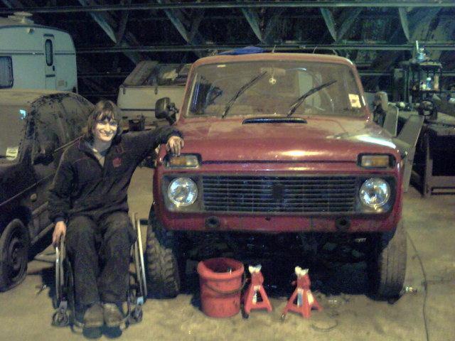
Lada Niva Front Crossmember Lift By Simon Allen
|
|
|
- Benedict Young
- 5 years ago
- Views:
Transcription

1 Lada Niva Front Crossmember Lift By Simon Allen This is to document how I did my front cross member lift for the Niva, as a few people have asked me now. This is just a guide, and already there have been variations of the theme where people have made it their own. The way I did mine, require a spare cross member to be able to use as a donor, but you can get around it, I'll show a pic of that later. Firstly, we assume that the cross member is off the vehicle. I made three spacers out of round pipe (I used 42mm OD x 3mm wall mild steel) and some thick washers. You will need 6: Weld one washer to one end of each tube. leave the other one off, as the bolts that come through the chassis to mount the cross member are captive, and REAL hard to get out without making a mess. You will need to slide these onto the bolts that come through the chassis, and hold the cross member in place on a jack, so that you can get the postitioning right, while you tack in braces to hold these solid:


2 I then made braces to go in between all of these, to give the whole thing a lot of strength. I didn't take a photo if the in between, but I used the same spec tube as I did to make the spacers, and ended up with this: you can then bolt them to the car (should have two of these at this point, one for each side).

3 Now you need to weld some m12x25 bolts through the washers that you didnt weld onto the spacers. These are to create a thread to mount the cross member with. Once this is done you can weld the washers to the bottom of the spacers on the car, which will then mean that you can't get to the nuts on the chassis now, so make sure they are TIGHT first, and put a tack weld on them so there is no way of them coming loose under usage. Once the spacers are completed, you can bolt the cross member to the car: now you need your donor cross member. you need to cut underneath the 3rd bolthole down. This is so that you have enough holes for the engine mount etc etc to stay in the standard place when the whole thing is finnished. should look like this:


4 you can see that these are the top bits of the donor cross member. You need to clean the edge up that you have cut, and make sure you have a good chamfer ground all the way around it, so that the weld can get a good penetration later. You then need to mark where you need to cut the cross member that is on the car. I did this by eye first, then got it down exactly using the grinder after. You need to make sure that the second set of holes line up with those going through the chassis, as these will be bolted together in the end. Will look like this:

5 As you can see, the bolt holes for the top wishbone are in the standard location, as are those for the engine mounts. Nice eh Get a good weld in there to hold it all together. I would advise bolting through the chassis as shown in the above picture, as if you're welding it right the heat will cause things to want to move. When both sides are welded, you need to REMOVE the cross member (again!) and weld the side of the cross member that was previously hidden from the welder by the spacer, don't skimp on this, it's a ballache taking it all apart again but your safety! You will now need to make a spacer for the upper ball joint, as you have essentially moved the buh away from it. Mine are constructed of three pieces of tube with an 8mm inside diameter, and a larger piece of tube for the center, although I forgot the dimension for that but basically it needs to go over the "lump" on the back of the ball joint, and be big enough to reach the smaller three tubes when they are all bolted up. I mocked it all together by bolting it all together with the ball joint and upper wishbone. I came out with this:

6 (note that's the part's car, NOT my shell. I wouldn't be building a v6 into a shell with holes that big in it!! lol) You're pretty much done now, just a few things remain. you need to build everything back up again as it would have been before. engine mounts in, upper wishbone in, you're front diff will need lowering by the same amount as what you have dropped your cross member by (i'm sorry, I can't tell you how to do this, as my setup is different due to using a steel diff casing and mounting it to the cross member). Also the arms that connect your track rod to the hub, will need swapping from side to side. this is to correct the angle of the steering arms, as the track rod end will now go in from the top of the hub, not the bottom. There are two small rods that run from the anti roll bar mounts on the chassis to the cross member also. these will need bending down slightly, and also possibly lenghtening a little. If you've got this far, that bit will be easy When assembled you will have something that looks a little like this:
 as they were the right length for my lift (2.75\").")
7 (note my steering arms weren't done then but you get the idea) You will notice that your front dampers are now too short... You can either modify the upper mounts to use your stanard ones, or I used the rear dampers off an old mini (they were new dampers though ) as they were the right length for my lift (2.75"). your sump protector will also no longer fit, but I haven't made mine yet so I can't tell you how I did it!! so when all is put back together your niva will be sitting pretty at it's new ride height. The beauty of the way I did it, is that the lift amount is infinately variable by what you want. it is taken up by where you cut the two cross members. *****I ALSO HAVE TO STRESS****** the quality of your welding needs to be of a high standard. This is because the whole front suspension setup of your niva relies on welds that you have done. I used a 165amp mig turned up to the max for this. I can't be held responsible for anyone following my guidelines (and that's all they are!!) of how I did mine. I could do without people holding me responsible if an inadequate weld potentially killing someone. you have been warned!! With that aside, enjoy your now lifted niva front end I know I like mine!!
8
Installation Instructions Universal Crossmember Kit - 60 Track Width BEFORE Measure Twice, Weld Once! II
 Installation Instructions Universal Crossmember Kit - 60 Track Width Please read these instructions completely BEFORE starting your installation. Remember the basic rule for a successful installation:
IIHS Side Impact Outrigger
 IIHS Side Impact Outrigger Assembly Procedure Base Assembly (14.3 lbs) The base assembly consists of a ¼ thick steel plate, a ¼ thick piece of polyethylene, and mounting fixtures for the upper and lower
Sheet Metal Brake Plans for a 6' Sheet Metal Brake
 Sheet Metal Brake Plans for a 6' Sheet Metal Brake,1752'8&7,21 Thank you for purchasing the sheet metal brake plans. The plans include a complete list of material needed and easy to follow steps to build
INSTALLATION INSTRUCTIONS FORD F-100 INDEPENDENT FRONT SUSPENSION
 INSTALLATION INSTRUCTIONS 65-79 FORD F-100 INDEPENDENT FRONT SUSPENSION Please read these instructions completely before starting your installation. Assemble suspension on vehicle before powder-coating
Important Note. Tools Required: Welder capable of fully welding 10 GA.135 steel
 INSTALLATION INSTRUCTIONS Frame Reinforcement Kit 11100 (Patent Pending) 1968-72 GM A-Body Coupe/Sedan Read Instructions FULLY before starting Installation Important Note Installation of this kit requires
INDEPENDENT FRONT SUSPENSION SWAP
 INDEPENDENT FRONT SUSPENSION SWAP 20 PHOTOS In this article we will show how to change out the old frame/front suspension of your 49, 50, and 51 Mercury / Ford to a new IFS unit. This high tech front suspension
Clayton Off Road COR COR COR
 Clayton Off Road COR-4806011 COR-4806021 COR-4806031 JEEP GRAND CHEROKEE WJ LONG ARM UPGRADE KITS (1999-2004 WJ) NOTES: This product requires general welding, fabrication and automotive mechanic skills.
XJ Coil Conversion Rear 4 Link Instructions
 Parts Checklist: Iron Rock Logo Decal 10001 (2) Rock-Link Decal 13287 (2) ironrockoffroad.com Decal (1) LCA/UCA Mounting Subframe 91162 (1) Shock crossmember 91173 (1) Shock crossmember spacer 91178 (2)
INSTALLATION INSTRUCTIONS CHEVY C-10 INDEPENDENT FRONT SUSPENSION
 INSTALLATION INSTRUCTIONS 73-87 CHEVY C-10 INDEPENDENT FRONT SUSPENSION Please read these instructions completely before starting your installation. Assemble suspension on vehicle before powder-coating
Installation Instructions Kit, Base Rail Bracket Part # 31413
 Installation Instructions Kit, Base Rail Bracket Part # 31413 Dealer / Installer: Provide a copy of these Instructions to the end user of this product. These Instructions provide important operating and
RACER TECH rzr lift kit installation instructions
 RACER TECH rzr 170 2 lift kit installation instructions Thank You for purchasing this kit. You should have received the following: (2) - Front spindle relocators (2) Front relocator shims (1) - Rear upper
You actually only need a couple of inches of stroke but longer is better as it allows more options for locating the press arm linkages.
 X-Press Type Press Requires Welding Author Unknown, but believed to be someone from ArcheryTalk.com Please note the construction of this press will require some general fabrication skills so if you struggle
USE THE PARTS LIST BELOW TO MAKE SURE YOUR KIT IS COMPLETE BEFORE INSTALLATION. IF ANY PIECES ARE MISSING, PLEASE CONTACT:
 1963-1972 C10 Chevy Truck Custom IFS Installation Instructions Tech line: 1-855-693-1259 www.totalcostinvolved.com Read and understand these instructions before starting any work! USE THE PARTS LIST BELOW
IBEX 1132 REAR AXLE UCA TRUSS GOAT BUILT IBEX REAR AXLE UPPER CONTROL ARM BRACKET/TRUSS
 GOAT BUILT IBEX REAR AXLE UPPER CONTROL ARM BRACKET/TRUSS Thank you for purchasing Ibex chassis kit components, before starting your build, we recommend that you read through these instructions to familiarize
Installation instructions for Standard front steer I.F.S.
 Installation instructions for Standard front steer I.F.S. Scotts Hotrods 3421 Galaxy Place Oxnard CA 93030 (805) 485 0382 Rev: A Installation Manual for Standard front steer IFS Please note a few things
Place the vehicle on a hard level surface and use an appropriate jack and jack stands to raise the vehicle of the ground.
 1937-1939 Chevy Truck Rear Air Bag 4 - Link Kit Installation Instructions 1-866-925-1101 www.totalcostinvolved.com CHECK ALL PARTS INCLUDED IN THIS KIT TO THE PARTS LIST BEFORE INSTALLATING OF THE KIT.
Bio-Sand Filtration Mould Construction Guidelines
 Bio-Sand Filtration Mould Construction Guidelines Adriaan Mol & Eric Fewster BioSandFilter.org December 19, 2007 Introduction On the following pages, you will find an illustrated construction guide that
Installation Instructions for FC2 & FC15 Forward Controls for the Super Magna
 Installation Instructions for FC2 & FC15 Forward Controls for the Super Magna It is highly recommended that you use a thread lock compound such as Loctite brand on all threads to keep them from vibrating
Can Am Renegade "X" 2ND Generation Lift Instructions
 Can Am Renegade "X" 2ND Generation Lift Instructions Renegade X Front Lift Kit Install -Lift ATV with some sort of ATV lift stand and remove front tires -Using a 15mm socket and a 15mm wrench, remove the
Installation instructions for FC17 Forward Controls for Triumph Rocket III Roadster
 Installation instructions for FC17 Forward Controls for Triumph Rocket III Roadster It is highly recommended that you use a thread lock compound such as Loctite brand on all threads to keep them from vibrating
Toyota 4 Runner and Lexus GX Skid Plate installation instructions.
 Toyota 4 Runner and Lexus GX Skid Plate installation instructions. NOTE: When installing the full set of skid plate start at the rear of the vehicle and work your way forward. NOTE: Torque Specs: Tighten
Important Note. Tools Required: Welder capable of fully welding 10 GA.135 steel
 INSTALLATION INSTRUCTIONS Frame Reinforcement Kit 11102 (Patent Pending) 1964-67 GM A-Body Coupe/2dr Sedan Read Instructions FULLY before starting Installation Important Note Installation of this kit requires
Making a Pan Brake "Folder with fingers" for home
 Making a Pan Brake "Folder with fingers" for home By Simso Taken from: http://www.woodworkforums.com/showthread.php?t=45792 Okay, just a quick overview of what were dealing with here. Grahame posted up
BMW E46 Coupe 3dr MP Bolt in (BMW Race Days Only) Roll Cage (B045) Fitting Instructions
 Roll Cage (B045) Fitting Instructions") BMW E46 Coupe 3dr MP Bolt in (BMW Race Days Only) Roll Cage (B045) Fitting Instructions Unwrap the mounting points/ends of the roll cage and unpack the individual fitting kits. Try to leave wrapping on
BMW E46 Coupe 3dr MP Bolt in (BMW Race Days Only) Roll Cage (B045) Fitting Instructions Unwrap the mounting points/ends of the roll cage and unpack the individual fitting kits. Try to leave wrapping on
Making a 1911 frame from scratch the easy way. 7 parts make up the frame in a 1911 pistol,
 Making a 1911 frame from scratch the easy way. 7 parts make up the frame in a 1911 pistol, The rails and fire control block- needs to be as strong as a standard one piece frame The grip sides (2 off) -
Hardware and Components:
 Hardware and Components: (A) 5/16 x 2 Hex Bolt (B) 5/16 x 2-1/4 Hex Bolt (C) 5/16 x 2-1/2 Hex Bolt (D) 4X 5/16 x 3/4 Hex Bolt (E) 4X 5/16 x 1-1/4 Hex Bolt (F) 11X 5/16 Flat Washer (G) 12X 5/16 Nylock Nut
1949 to 1954 Chevrolet Dual Master Cylinder Conversion
 1949 to 1954 Chevrolet Dual Master Cylinder Conversion This document is a one stop shop to getting your brake system updated on your old Chevy. Whether you re going with a disc conversion or just sticking
USE THE PARTS LIST BELOW TO MAKE SURE YOUR KIT IS COMPLETE BEFORE INSTALLATION. IF ANY PIECES ARE MISSING, PLEASE CONTACT:
 1967-1969 Cougar Custom IFS Install Sheet Tech Line: 1-855-693-1259 www.totalcostinvolved.com Read and understand these instructions before starting any work! USE THE PARTS LIST BELOW TO MAKE SURE YOUR
Please read these instructions all the way through before starting, since the order of work is important.
 Due to the many differing vehicles to which Safety Devices roll cages can be fitted, these instructions are of a general nature and not specific to your vehicle. Important Note Roll bars and/or front cages
Kai Installation Instructions
 Kai Installation Instructions Before Beginning Installation Read through the entire instruction thoroughly A minimum of 2 people are required for this assembly These instructions reflect typical assemblies;
HMP-200 BENDER INSTRUCTION SET
 HMP-200 BENDER INSTRUCTION SET HMP-200 BENDER ASEMBLY INSTRUCTIONS STEP 1 STEP 2 BOLT LEFT SIDE PLATE TO BASE AS SHOWN WITH 1/2 x20 HEX BOLT & FLAT WASHER WELD BASE TO PLATE ON EACH SIDE NOTE: OFFSET HOLE
It is highly recommended that you use a thread lock compound such as Loctite brand on all threads to keep them from vibrating loose.
 Installation instructions for FC12 Forward Controls for Kawasaki Vulcan 750 It is highly recommended that you use a thread lock compound such as Loctite brand on all threads to keep them from vibrating
Installation instructions for FC9 & FC18 Forward Controls for Yamaha V-Max
 Installation instructions for FC9 & FC18 Forward Controls for 1985-2007 Yamaha V-Max It is highly recommended that you use a thread lock compound such as Loctite brand on all threads to keep them from
BOLT ON LONG TRAVEL FOR E-Z-GO
 INSTALLATION INSTRUCTIONS BOLT ON LONG TRAVEL FOR E-Z-GO 1994 2000 Model E-7-04 E-7-06 TABLE OF CONTENTS Progressive Supension Kit... 2 Kit Contents...3-4 Disassembly...5-10 Frame Assembly...11-14 Frame
1964 ½ Mustang Front Suspension Installation Instructions
 1964 ½ - 1970 Mustang Front Suspension Installation Instructions 1-800-984-6259 www.totalcostinvolved.com All engine installations with this front end will require a rear sump oil pan. 289-302 Small Block
Fairlane Front Suspension Install Sheet
 1966-1967 Fairlane Front Suspension Install Sheet 1-866-925-1101 Read and understand these instructions before starting any work! 1966-1967 Fairlane Front Suspension Installation Instructions Thank you
RZR 900 XC/Trail 2 Lift Kit
 RZR 900 XC/Trail 2 Lift Kit Polaris RZR 900 XC/Trail 2015+ Part #: 5101256 Rev. 060817 491 W. Garfield Ave., Coldwater, MI 49036. Phone: 517-278-7768 E-mail: sales-rtpro@sporttruckusainc.com SAFETY WARNING
FIRST TEAM SPORTS, INC.
 FIRST TEAM SPORTS, INC. INVADER EZ-CRANK PORTABLE BASKETBALL GOAL ASSEMBLY INSTRUCTIONS Revised - 08/04/10 BILL OF MATERIALS (1) BASE TANK (1) BACKBOARD MOUNT (2) 5/16 X ¾ HEX BOLT (1) LOWER POST (2) SPRING
Rudders Removal and Stuffing Box Packing by Brian Barton May 31, 2013
 Rudders Removal and Stuffing Box Packing by Brian Barton May 31, 2013 Last year both rudders on my 38 Commander were leaking a little less than a water fall. An adjustment worked on the starboard side.
How We Installed Our 3-Link Banana Bracket:
 How We Installed Our 3-Link Banana Bracket: General Description To avoid failure of your 3-link banana bracket, you will need to pay special attention to the installation. The clamp-on feature of the design
8mm x 25mm "Z" Bolt Plates. (2) Tube Spacers. (2) 12mm Bolt Plates w/ Nut
 Tube Spacers. (2) 12mm Bolt Plates w/ Nut") PARTS LIST: 1 Grille Guard 10 12mm Lock Washers 1 Driver/Left Side Frame Mounting Bracket 8 12mm Hex Nuts 1 Passenger/Right Side Frame Mounting Bracket 2 10-1.50mm x 25mm Button Head Bolts 1 Driver/Left
PARTS LIST: 1 Grille Guard 10 12mm Lock Washers 1 Driver/Left Side Frame Mounting Bracket 8 12mm Hex Nuts 1 Passenger/Right Side Frame Mounting Bracket 2 10-1.50mm x 25mm Button Head Bolts 1 Driver/Left
Installation instructions for FC14S Forward Controls for Shadow ACE and Aero 1100
 Installation instructions for FC14S Forward Controls for Shadow ACE and Aero 1100 It is highly recommended that you use a thread lock compound such as Loctite brand on all threads to keep them from vibrating
Please read the instructions completely BEFORE starting this project.
 Please read the instructions completely BEFORE starting this project. Rhodes Race Cars 10 Point Roll Cages are not designed for use in vehicles where the stock floor has been removed. Check your sanctioning
Installation Instructions Kit, Base Rail Bracket Part # 31413
 Installation Instructions Kit, Base Rail Bracket Part # 31413 Dealer / Installer: End User: Provide a copy of these Instructions to the end user of this product. These Instructions provide important operating
METAL BENDER OPERATING & MAINTENANCE INSTRUCTIONS Model Nos: CCB1 & CCB2 Part Nos: & CCB2 CCB1
 METAL BENDER Model Nos: CCB1 & CCB2 Part Nos: 7630073 & 7630074 CCB2 CCB1 OPERATING & MAINTENANCE INSTRUCTIONS 1206 1 The Compact Bender allows you to economically make a variety of bends in flat, square,
INSTALLATION INSTRUCTIONS
 TEL:1-866-XANATOS INSTALLATION INSTRUCTIONS PART # RN-FOF1SCC-09-91 CUTLASS RUNNING BOARDS PARTS LIST: 5 STAINLESS AND ALUMINUM SIDEBARS 2 Left or right Sidebars 10 8-1.25mm x 30mm Hex Bolts 2 Driver/Left
MM750 Installation Instructions
 MM750 Installation Instructions IMPORTANT SAFETY INSTRUCTIONS - SAVE THESE INSTRUCTIONS Please read this entire manual before you begin. Do not unpack any contents until you verify all requirements on
German Auto Solutions BMW Monoball Kit Installation DIY
 Home Store Tool Rental BMW Products DIY Instructions Engine Services Dyno Services Machining Contact About German Auto Solutions BMW Monoball Kit Installation DIY BMW E39-E60-E90 G.A.S. Monoballs Installation
TIRE RACK INSTALLATION INSTRUCTIONS Dodge Sprinter
 Aluminess Products Inc 9402 Wheatlands Ct. #A Santee, CA 92071 619-449-9930 TIRE RACK INSTALLATION INSTRUCTIONS 07-11 Dodge Sprinter Please read before beginning Stainless steel hardware may bind together
FW450/550 Multifunction Landing Strut Set
 FW450/550 Multifunction Landing Strut Set 1 Copyright 2013 PhotoShip One LLC - www.photoshipone.com Assemble the clamp pieces with M3x8 screws The Multifunction Landing strut set is intended to provide
INSTALLATION INSTRUCTIONS 8-POINT ROLL BAR (TRUCK) Please read the instructions completely BEFORE starting this project.
 Please read the instructions completely BEFORE starting this project.") INSTALLATION INSTRUCTIONS 8-POINT ROLL BAR (TRUCK) Please read the instructions completely BEFORE starting this project. Competition Engineering 8-Point Roll Bars are not designed for use in vehicles where
INSTALLATION INSTRUCTIONS 8-POINT ROLL BAR (TRUCK) Please read the instructions completely BEFORE starting this project. Competition Engineering 8-Point Roll Bars are not designed for use in vehicles where
INSTALLATION GUIDE Rear Bumper. Jeep JL Wrangler
 INSTALLATION GUIDE Rear Bumper Jeep JL Wrangler Dual Swing System 1A From the stock bumper you removed from vehicle, you ll need to take the parking sensor wiring from it and feed it into the new bumper.
Steel Framed Miter Saw Bench
 Steel Framed Miter Saw Bench Version 1.1 How to build Steel Framed Miter Saw Bench With easy to follow step-by-step instructions, you will be able to cut, assemble, and finish your very own steel miter
Rockin' the Rockers. Ed Hollingsworth
 Rockin' the Rockers Ed Hollingsworth I'm spending my spare time these days rebuilding a 1974 Triumph TR6. I had the well-worn 2.5 liter straight six engine all apart, and was assessing the toll that 40
FRONT BUMPER INSTALLATION INSTRUCTIONS Toyota 4Runner
 Aluminess Products Inc 9402 Wheatlands Ct. #A Santee, CA 92071 619-449-9930 FRONT BUMPER INSTALLATION INSTRUCTIONS 2003-2009 Toyota 4Runner Please read before beginning Stainless steel hardware may bind
How To Build A Tube Bender by Terry Tasky
 How To Build A Tube Bender by Terry Tasky I would like to thank the good people at Blind Chicken Racing for supplying the basics to make this bender. I have taken their project a step further and have
PORTABLE ADJUSTABLE BASKETBALL SYSTEM
 Instruction Manual PORTABLE ADJUSTABLE BASKETBALL SYSTEM P A R T S L I S T 5 1/2 and 8 safe play clearance Item Qty Description Item Qty Description A 1 Portable Base Assembly M 4 1/2 Lock Nut B 2 Front
Hardware and Components:
 Hardware and Components: (A) 4X 5/16 x 1 Carriage Bolt (B) 2X 5/16 x 2-1/4 Carriage Bolt (C) 2X 5/16 x 3-1/4 Hex Bolt (D) 2X 5/16 x 3/4 Hex Bolt (E) 2X 5/16 x 1-1/4 Hex Bolt (F) 5/16 x 2-1/4 Hex Bolt (G)
Tools required for basic assembly/checking
 ... and for choosing RKR BMX, you have chosen wisely! RKR is very different from other mini bike brands on the market; It was designed by riders, for riders and is the product of many years experience
F i t t i n g t h e N e w L a n d i n g G e a r t o Y o u r S k y J i b V 1
 F i t t i n g t h e N e w L a n d i n g G e a r t o Y o u r S k y J i b V 1 1 P a r t s L i s t : S t a n d a r d L a n d i n g G e a r U p g r a d e Product Code Parts + Spares Product Code Parts + Spares
"The Stick" Assembly Instructions
 Back to Main Page "The Stick" Assembly Instructions In Japanese (pdf): right click and save target as. Introduction: Hello and thank you for buying a Stick chassis from TCS. We appreciate your business
Thor Audi A4/S4 Skid Plate Installation Instructions
 Thor Audi A4/S4 Skid Plate Installation Instructions Parts List: 1 Aluminum Skid Plate 2 Aluminum Side Wings 10 10mm Flat Washers 3 8mm Flat Washers 3 8mm Speed Clips 2 10x40mm Bolts 3 8x35mm Bolts 2 Rivet-nuts
Bio-Sand Filtration Mould Construction Guidelines
 United Kingdom The Shieling, Wreay Carlisle CA4 0RL Tel: +44 (0)1697 47 5369 Mobile: +44 (0) 7739 665 777 Email: info@biosandfilter.org Madagascar Libanona Americain PB 307 Fort Dauphin (614) Tel: +261
Krypt Pro Air EXPLODED VIEW OF THE PRO AIR TOWER
 Krypt Pro Air EXPLODED VIEW OF THE PRO AIR TOWER STEP 1: Unpack and check the contents of the box. Check the parts list and the Instruction Guide correspond with the product you purchased. Ensure you have
RZR XP/XP4 900 Weld-In Gusset Kit
 RZR XP/XP4 900 Weld-In Gusset Kit Polaris RZR XP/XP4 900 2011-2014 Part #: 5501805 Rev. 051517 491 W. Garfield Ave., Coldwater, MI 49036. Phone: 517-278-7768 E-mail: sales-rtpro@sporttruckusainc.com SAFETY
INSTALLATION INSTRUCTIONS SIDE BAR FORD ESCAPE & MAZDA TRIBUTE PART #
 INSTALLATION INSTRUCTIONS SIDE BAR 2008-2010 FORD ESCAPE & MAZDA TRIBUTE PART # 50136 50137 PARTS LIST: 1 Driver/Left Sidebar 2 10-1.50mm x 35mm Bolt Plate 1 Passenger/Right Sidebar 2 10-1.50mm x 30mm
BUMP GATE FITTING INSTRUCTIONS.
 1 BUMP GATE FITTING INSTRUCTIONS. HEAVY DUTY MODEL FOR STEEL POSTS. Hinge post Lock post Bump arms Two-way lock Thank you for purchasing a Bump Gate. This device will provide you with many years of good
Please read the instructions completely BEFORE starting this project.
 Please read the instructions completely BEFORE starting this project. Rhodes Race Cars 8-Point Roll Bars are not designed for use in vehicles where the stock floor has been removed. Check your sanctioning
7x --Tailstock Cam Lock
 7x --Tailstock Cam Lock By Magic Brian magicbrian40@yahoo.com Probably the most pleasing mod to have, but often not done through lack of milling facility s This version does NOT require a mill. MATERIALS
Page 1 of 12 GENERAL INSTRUCTIONS KHJKK Installation
 Page 1 of 12 KHJKK PICTURE ABOVE IS THE UNIVERSAL KIT; YOUR KIT MAY BE DIFFERENT. THIS KIT INCLUDES: 8 M8-1.25X30MM BOLTS WITH WASHERS 8 M8-1.25X40MM BOLTS WITH WASHERS 2 PINS RIGHT AND LEFT HINGE ASSEMBLY
Shay - Boiler Cosmetics - Part I
 Shay - Boiler Cosmetics - Part I Nelson Riedel Nelson@NelsonsLocomotive.com Initial:3/01/04 Last Revised: 06/06/2004 I'd been dreading dealing with the exterior of the boiler because sheet metal is involved.
VIEWPOINT ALUMINUM RUNNING BOARD TOYOTA RAV4
 PARTS LIST: VIEWPOINT ALUMINUM RUNNING BOARD 1 Driver/Left Running Board 4 10-1.5mm x 50mm T-Bolt 1 Passenger/Right Running Board 12 10mm Plastic Retainers 1 Driver/Left Bracket 2 10-1.50mm x 40mm Hex
FITTING GUIDE - RIGHT HAND SILL TANK 110/130
 FITTING GUIDE - RIGHT HAND SILL TANK 110/130 STEP 1 - RIGHT HAND SILL TANK 110/130 The brackets are designed to fit to pre existing holes in the chassis, however given the high precision and meticulous
Step 1: Gather your parts!
 Step 1: Gather your parts! Show All Items The #mearm was designed with economy in mind. It is understood that laser cutters aren't the most common tools but there are more of them out there now than
S48-L12-SC AND G48-L12-GC STEEL PORTA-DOCK S82 SC 6 X 12 PLATFORM AND G82 GC 6 X 12 PLATFORM
 PAGE 1 OF 6 PORTA-DOCK, INC. S48-L12-SC AND G48-L12-GC STEEL PORTA-DOCK S82 SC 6 X 12 PLATFORM AND G82 GC 6 X 12 PLATFORM Thank you for purchasing our product! *Please read these instructions and follow
Camaro License Plate Frame Bracket, V8
 PART #59389 2010-11 Camaro License Plate Frame Bracket, V8 PACKING LIST Before installation, use this checklist to make sure all necessary parts have been included. ITEM QTY CHECK PART NUMBER DESCRIPTION
Replacing the Spindle Bearings Detailed Instructions
 Replacing the Spindle Bearings Detailed Instructions These are detailed instructions on how to replace the spindle bearings on a 9x20 lathe sold by many suppliers and made in China. The YAHOO 9x20Lathe
400A 40113V, 401A 40120V, & 401AL 40120VL ALUMINUM VERTICAL 4000 LB LIFT INCLUDES SCREW LEG ASSEMBLY INSTRUCTIONS
 12/11/07 PAGE 1 OF 12 400A 40113V, 401A 40120V, & 401AL 40120VL ALUMINUM VERTICAL 4000 LB LIFT INCLUDES SCREW LEG ASSEMBLY INSTRUCTIONS Thank you for purchasing our product! *Please read these instructions
MIG / TIG / PLASMA WELDING CART
 MIG / TIG / PLASMA WELDING CART INSTRUCTIONS Part #11616 This welding cart was designed by The Eastwood Company to make storage, accessibility, and maneuverability of your welders easier than ever before.
Written By Phil (T90) for Team MudRhino
 for Team MudRhino") Rock Sliders Written By Phil (T90) for Team MudRhino WWW.MUDRHINO.COM.AU The most vulnerable cosmetic part of any vehicle while off-roading is the door sills (rocker panels), located just under the doors.
Rock Sliders Written By Phil (T90) for Team MudRhino WWW.MUDRHINO.COM.AU The most vulnerable cosmetic part of any vehicle while off-roading is the door sills (rocker panels), located just under the doors.
Want to make a travel scope but too lazy to read the whole thing? Read this:
 My 114mm Travel Scope by Cyrille de Brebisson of Rhône-Alpes, France cyrille.de.brebisson@gmail.com During my last trip in the US, I was able to pick a 114mm/25.4mm primary/secondary mirror pair for 18$
INSTALLATION INSTRUCTIONS 3 BULL BAR 99-04, 04 "HERITAGE" F-150/250LD 2WD, 97-04, 04 "HERITAGE" 4WD WD EXPEDITION/ WD EXPEDITION PART
 INSTALLATION INSTRUCTIONS 3 BULL BAR PART #B-F1971;B-F2971 PARTS LIST: 1 Bull Bar 2 12-1.75mm x 130mm x 40mm Hex Bolts 1 Driver/Left Mounting Bracket 4 12-1.75mm x 35mm Hex Bolts 1 Passenger/Right Mounting
DTU Animal Cart Programme
 DTU Animal Cart Programme TECHNICAL 25 LIGHT STEEL AND WOOD DONKEY CART RELEASE Development Technology Unit, Department of Engineering, University of Warwick, Coventry, CV4 7AL UK, tel: +44 (0)203 523523
00108/00110 INSTRUCTION MANUAL
 00108/00110 INSTRUCTION MANUAL Removable and Adjustable Mudflap System IMPORTANT! Exhaust Systems Note: Any modifications to the factory installed exhaust system may void your manufacturer s warranty.
(6) Plastic Retainers. Passenger/Right. Passenger/Right Support Brackets
 Plastic Retainers. Passenger/Right. Passenger/Right Support Brackets") PART#R102580 PARTS LIST: 1 Driver/Left HD Running Board 4 8mm Bolt/Nut Plates 1 Passenger/Right HD Running Board 4 8mm Plastic Retainers 2 Driver/Left & Center Mount Bracket 14 8mm-1.25 x 30mm Hex Bolts
PART#R102580 PARTS LIST: 1 Driver/Left HD Running Board 4 8mm Bolt/Nut Plates 1 Passenger/Right HD Running Board 4 8mm Plastic Retainers 2 Driver/Left & Center Mount Bracket 14 8mm-1.25 x 30mm Hex Bolts
INSTALLATION INSTRUCTIONS Product No. MULTI-FIT PICK-UP
 INSTALLATION INSTRUCTIONS Product No. You can take it with you. PLYMOUTH, MICH. MULTI-FIT PICK-UP 37034 SMALL PARTS PACKAGE 37424 WARNING: DO NOT LUBRICATE THREADS, BOLT FAILURE MAY OCCUR DUE TO OVER TIGHTENING.
MM340 Installation Instructions IMPORTANT SAFETY INSTRUCTIONS - SAVE THESE INSTRUCTIONS
 MM30 Installation Instructions IMPORTANT SAFETY INSTRUCTIONS - SAVE THESE INSTRUCTIONS Please read this entire manual before you begin. Do not unpack any contents until you verify all requirements on PAGE.
Passenger/Right Center and Rear Support Brackets. Driver/Left Center and
 PARTS LIST: 1 Driver/Left HD Running Board 24 8mm x 24mm OD x 2mm Flat Washers 1 Passenger/Right HD Running Board 12 s 3 Driver/Left front, passenger center/rear Support Brackets 6 8mm-1.25 Hex Nuts 3
It is highly recommended that you use a thread lock compound such as Loctite brand on all threads to keep them from vibrating loose.
 Installation instructions for JM1 Jerry Can Mount for Toyota FJ Cruiser It is highly recommended that you use a thread lock compound such as Loctite brand on all threads to keep them from vibrating loose.
C4 Toe Rod Installation Document #: C4TR-1, sheet 1 of 6
 Document #: C4TR-1, sheet 1 of 6 READ ALL THE INSTRUCTIONS BEFORE BEGINNING INSTALLATION. There are two methods for installing the toe rods. You may find one more suitable to your situation OR you may
SECTION 2: INSTALLATION
 SECTION 2: INSTALLATION 2.1 PEDESTAL ASSEMBLY The T4000 pedestal is designed to support 100% of the weight of the ATM. Installed properly, the wall should not carry any load. Below represents the assembled
Kawasaki Mule Pro Upper Doors #06020 Installation & Operations Manual
 Kawasaki Mule Pro Upper Doors #06020 Installation & Operations Manual Before You Start: Please familiarize yourself with all the steps before beginning assembly. Compatibility Info: This Door System is
Building Rudy Kouhoupt s Walking-Beam Engine
 Building Rudy Kouhoupt s Walking-Beam Engine Some time ago I came across a copy of Rudy Kouhoupt s article: "Build this Walking-Beam Engine" (Popular Mechanics August 1969), and decided to try and make
HalfSpec Engineering S2000 Antenna kit Installation Tutorial
 HalfSpec Engineering S2000 Antenna kit Installation Tutorial What you ll need: Revision 1 Medium to small phillips head screw driver Flat head or a slotted tool to remove the stock antenna cap/nut 10mm
INSTALLATION MANUAL IOWA MOLD TOOLING CO., INC. BOX 189, GARNER, IA MANUAL PART NUMBER:
 PARTS-1 Model 24562/28562 Crane INSTALLATION MANUAL IOWA MOLD TOOLING CO., INC. BOX 189, GARNER, IA 50438-0189 641-923-3711 MANUAL PART NUMBER: 99903701 Iowa Mold Tooling Co., Inc. is an Oshkosh Truck
re3d Assembling Gigabot: "Flatpack"
 re3d Assembling Gigabot: "Flatpack" Your Gigabot was assembled, calibrated, tested, and taken apart for shipping purposes. All you need to do is reassemble it, and you're ready to go! Written By: Chris
U.S. Rack, Inc Falcon Drive, Madera, CA APR17 INSTALLATION AND USE INSTRUCTIONS for SIDE-MOUNT LADDER RACK
 U.S. Rack, Inc. 2850 Falcon Drive, Madera, CA 93637 15APR17 INSTALLATION AND USE INSTRUCTIONS for SIDE-MOUNT LADDER RACK WARNING: Do NOT attempt to install or use this rack without following all instructions.
WEAR SAFETY GLASSES WHEN INSTALLING THIS KIT.
 INSTALLATION INSTRUCTIONS Trans4mer Mounting Systems Part No. 29753 (black) Part No. 65654 (stainless) for full size GM pickups, and Blazer, Yukon, Suburban, Tahoe As you read these instructions, you will
Precision Steel Car s 100 T Steel Coil Car
 Precision Steel Car s 100 T Steel Coil Car Precision Steel Car www.precisionsteelcar.com info@precisionsteelcar.com Paul Vernon: (513) 571-5739 Revised 4/30/2009 Contents of Kit Main Tube Side Frame 2
Ratcheting and Angled Leg Vises. Ratcheting Parallel Guide
 Ratcheting and Angled Leg Vises Ratcheting Parallel Guide In Scott Landis s The Work Bench Book there is a drawing of a ratchet mechanism for a parallel guide. It was one of those little tidbits I tend