INSTALLATION INSTRUCTIONS FORD F-100 INDEPENDENT FRONT SUSPENSION
|
|
|
- Hugh Davidson
- 5 years ago
- Views:
Transcription


1 INSTALLATION INSTRUCTIONS FORD F-100 INDEPENDENT FRONT SUSPENSION Please read these instructions completely before starting your installation. Assemble suspension on vehicle before powder-coating to ensure proper fitment, and to make modifications if necessary.
2 PARTS LIST 1) Ford Bolt-On Crossmember 2) Spindles 2) 1-1/4 Upper Control Arms 1) Power Rack & Pinion 3) 1-1/2 Lower Control Arms 2) Adjustable Shocks 2) Chrome Springs 1) Wilwood Brake Kit Hardware Package 8) 1 3/8 Stainless Steel Washers 30) ½ -20 x 1 ½ Hex Bolts 2) 5/8-18 Nylock Nuts 60) ½ Washers 2) 5/8-18 Nylock Jam Nuts 34) ½ -20 Nylock Nuts 2) ½ -20 x 2 ½ Hex Bolts 2) ½ -20 x 8 ½ Hex Bolts 2) 5/8-18 x 11 Hex Bolts 2) 5/8-18 x 13 Hex Bolts

 Begin your installation by jacking up your vehicle and supporting it on sturdy jack stands. The stands must be placed on the flat section of the frame rails close to the front body mounts.")
3 You are about to install your HEIDTS suspension system. You are probably wondering how complicated installing a complete I.F.S. system really is, with all those pieces, all the angles, antidive, geometry...don't worry. The HEIDTS I.F.S. kits are designed so all that is taken care of for you. Just follow the instructions step by step, reading each step completely, and in a very short time your truck will be sitting on the nicest riding I.F.S. kit available. 1) Begin your installation by jacking up your vehicle and supporting it on sturdy jack stands. The stands must be placed on the flat section of the frame rails close to the front body mounts. Remove the engine, transmission, hood and fenders. SAVE AND LABEL ALL FASTENERS FOR RE-INSTALLATION! Remove the front wheels and shocks. Disconnect the brake lines, tie-rods, and I Beams. Next, remove the old steering box, pitman arm, and the steering column. (See Figure 1). You cannot reuse the original steering column. Figure 1 2) Before removing the old crossmember and spring hats from the frame. Weld a piece of angle iron or tubing to keep the frame rails from moving during the uninstalling of the factory cross member. See Figures 2 through 4. Figure 2


4 Figure 3 Figure 4 3) The F-100 has existing factory holes on the frame rails. We will utilize two holes on each side of the frame to mount the front cross member. Take a rough measurement from the bottom of the front of the frame. The factory holes are roughly located 26 ¼ and 31 7/8 from the front. Drill these holes out to ½. There are two holes on each side. See Figures 5-7. Figure 5 Figure 6 Figure 7

 Place a straight edge underneath the frame of the front sway bar bolt.")
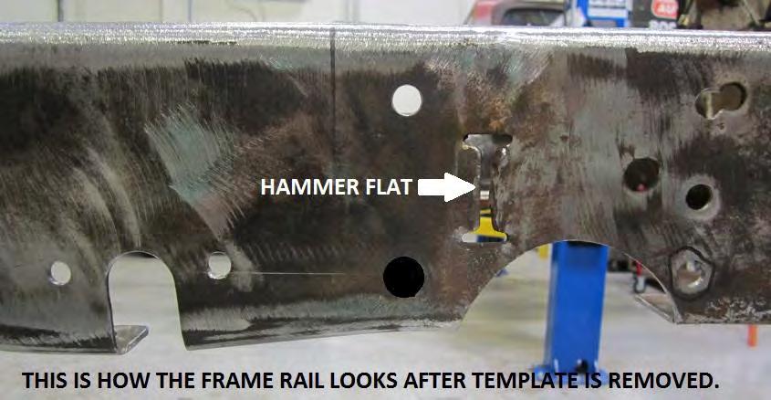
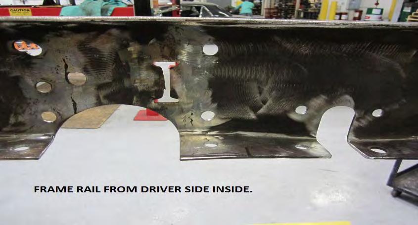
5 4) Use the installation template in the kit for the next step. Place installation template on the frame rails utilizing the pre existing frame holes. Bolt the template to the frame using ½-20 x 1 ½ grade 8 bolts and a clamp for the opposite side. (See Figure 8) Place a straight edge underneath the frame of the front sway bar bolt. (See Figure 9) Use a sharpie to mark the cut outs for the rack and pinion and sway bar. Use a 7/16 center punch for the two front sway bar holes. See Figure 10.Repeat this step for the passenger side. See Figures Figure 8 Figure 9


6 Figure 10 Figure 11 Figure12 Figure 13


7 5) After the holes are dilled and the frame is cut for the rack and pinion and sway bar it is time to install the front cross member. Place the cross member inside the frame rails close to the holes you previously drilled. See Figure 14. Next install the lower frame mounts utilizing the holes previously drilled to locate the mount. Install both sides. See Figure 15. Figure 14 Figure 15


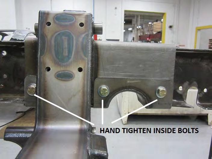
8 6) Notice the holes inside the lower frame mounts. These three holes locate the front cross member. Use a drift pin to center all three holes with the cross member. Install ½- 20 x 1 ½ Grade 8 bolts, washers and Nylock nuts. Hand tighten the inside bolts to the main cross member. See Figures Figure 16 Figure 17

9 Figure 18 Figure 19


10 7) The next step will be squaring the front cross member. This is an important step before you drill the remaining holes in the frame. We will utilize a 5/8 factory frame hole that s approximately 7 from the body mount rivets inside the frame. See Figure 20. Figure 20 8) Measure from the rear of the lower frame mount to the start of the 5/8 factory frame hole. Measure both driver and passenger sides and square cross member until both measurements are the same. We measured 26 1/16 but due to factory tolerances your frame may be slightly different. See Figures 21 and 22. Figure 21 Figure 22


11 9) Once the cross member is squared, tighten the six inner frame bolts and four outer frame bolts. After the bolts are tightened, center punch the remaining twenty bolt holes on the cross member. Six holes on top, six on the bottom and eight on the sides. Once the holes are all center punched, drill all holes to ½. See Figures Figure 23 Figure 24 Figure 25


12 10) After the holes are all drilled, finish bolting in the front cross member using 30 ½-20 x 1 ½ grade 8 bolts, 60 washers and 30 nylock nuts. Tighten all nuts and bolts. See Figures 26 and 27. Figure 26 Figure 27
.")


13 11) Now the suspension components can be installed. Start with the upper control arms. Position the upper control arms where the threads for the ball joint are facing up. (See Figure 28). Before screwing in ball joints, remove boot, washer and castle nut that came with it in the package. It is VERY IMPORTANT to apply Anti-Seize to the threads before screwing in ball joints. Screw in ball joint by hand, until you cannot tighten it any further. Use a large crescent wrench or socket and tighten it further to ensure that it is completely screwed in all the way. Screw in grease fitting (See Figure 29). Next is installing the adjusters. Before screwing them in, apply Anti-Seize to the threads. Screw in until approximately four threads are left exposed. (See Figure 30). The adjusters will later be adjusted when setting the alignment of your vehicle. Finger tighten nuts to secure adjusters. Installing Ball Joint Figure 28 Tightening Ball Joint Figure 29

. Finger tighten for alignment later.")
14 Figure 30 12) To install upper control arms use the 5 / 8-18 x 11 Hex Bolts, 1 3 / 8 Stainless Steel Dished Washers, and 5 / 8-18 Nylock Jam Nuts provided. Position upper control arm against the upper control arm mount of the crossmember. If you have having trouble getting the control arm to fit, apply some silicon lubricant to the face of the mount on the crossmember. When installing, use washers on the outside of the control arms (See Figure 31). Finger tighten for alignment later. View From Drivers Side Figure 31


15 13) Next is preparing the lower control arms for installation. Repeat the process in Step 11 for installing the ball joint and grease fitting. Remember, you must apply anti-seize to the ball joint before installing it! After installing and tightening the ball joints in both lower control arms, install the bushings and bolt sleeves into the bushing cup. Install both bushing halves. Slide sleeve through the hole in the middle of the bushing. Apply silicon lubricant to sleeve if needed. Now you are ready to install the arms to the crossmember. To differentiate between which arm is right and left, observe where the sway bar mounts are. The sway bar mounts are facing the front of the vehicle. See Figure 32 Figure 32 14) To install the arms, use the 5 / 8-18 x 13 Hex Bolts, 1 3 / 8 Stainless Steel Dished Washers, and 5 / 8-18 Nylock Nuts provided. Use one washer directly between the bolt head and bushing, and another one between the bushing and nylock nut, See Figure 33. Figure 33


16 15) Next, the spindles can be installed. To differentiate between right and left, the steering arms should be facing the front of the vehicle. Also, to distinguish between the top and bottom, the section for mounting the lower ball joint is very short, and the part of the spindle that mounts to the upper ball joint is elongated. See Figure 34. Before installing the spindle, first place the boot on top of the ball joint cup. After mounting the spindle on the ball joint, install the provided gold-colored spacers. Next, screw on the castle nut. After tightening down the castle nut all the way, install the cotter pin and secure it by bending the tangs out. See Figures 35 and 36. Repeat for the passenger side. Figure 34 Figure 35 Figure 36
. Install castle nut and cotter pin.")


17 16) The next step is to bolt down the upper ball joint to the top of the spindle. Repeat the same procedure from Step 15, except this time using the single spacer (See Figure 37). Install castle nut and cotter pin. Repeat for the passenger side. Figure 37 17) At this point you are ready to install the shocks. To do so, use the 1 / 2-20 x 2-1 / 2 Hex Bolts, 1 / 2-20 x 8-1 / 2 Hex Bolts, and 1 / 2-20 Nylock Nuts. The adjusting knob will distinguish the bottom of the shock. Make sure that the adjusting knob is facing the crossmember. Slide the 1 / 2-20 x 8-1 / 2 Hex Bolts through the shock sleeve in the lower control arm, and use a 1 / 2-20 Nylock Nut and tighten all the way down. Do the same for the top in the upper shock mount, using the 1 / 2-20 x 2-1 / 2 Hex Bolts and another 1 / 2-20 Nylock Nut. See Figure 38. Do the same for the passenger side. Figure 38 A Figure 38 B


18 18) Now you are ready to install the steering rack. To do so, use the hardware package that came with the steering rack. Use the 5 / 8-11 x 4-1 / 2 Hex Head Bolts, 5 / 8 Flat Washer, Spacer, and 5 / 8 x 11 Flange Locknut. The input to the steering rack should be positioned on the drivers side. The order of the hardware is as follows: 5 / 8-11 x 4-1 / 2 Hex Head Bolt, 5 / 8 Flat Washer, Steering Rack, Spacer, Steering Rack Mount on the Crossmember, and lastly the 5 / 8 x 11 Flange Locknut. See Figure 15. Bottom View of Steering Rack Rear View of Steering Rack Figure 15
, slide the tie rod end through the steering arm of the")
19 19) The last step to installing the steering rack is bolting on the tie rod ends. Using two crescent wrenches, tighten up the nut and the tie rod end, (you ll adjust them later when setting the alignment of your vehicle), slide the tie rod end through the steering arm of the spindle. DO NOT tighten. Tie rod needs to be removed for sway bar installation.(see Figure 16). Figure 16 Lastly, you are ready to set the alignment of your vehicle. Be sure to do so with the arms and shocks set at ride height (the lower control arms should be level). The caster and camber settings are done with the adjusters in the upper control arms. Both adjusters are screwed in or out an equal amount to change the camber, and they are adjusted opposite each other to change caster. Approximately 3 of caster is built into the crossmember already, so not much change is required there. The interesting thing about the caster setting is that you can experiment with different settings and actually "tune" the characteristics of the handling of your truck to your driving style. 3 of caster will give a nice road feel and good low speed driveability. 4 or 5 will yield better high speed stability and tracking, putting a better self-centering characteristic in the steering wheel, but will tend to start to make parking slightly more difficult. Have fun with this one, as it truly makes your truck your own truck. Just be sure that both sides have equal caster settings, or the truck will tend to pull to one side. Alignment Specifications: Caster: 3-4 Positive Camber: Negative Toe: 0-1/16 Toe-In
20 Since you are now to the point where you have a finished, running truck (we hope!) it is time to test drive it. After a few hundred miles, double check the ride height and the alignment. The springs may have settled, which would change the ride height and the camber setting. Readjust the ride height before changing the alignment. After this initial setting period, the springs and bushings should have pretty much taken their final set, so you should be on your way to many miles of cruising in style.
INSTALLATION INSTRUCTIONS CHEVY C-10 INDEPENDENT FRONT SUSPENSION
 INSTALLATION INSTRUCTIONS 73-87 CHEVY C-10 INDEPENDENT FRONT SUSPENSION Please read these instructions completely before starting your installation. Assemble suspension on vehicle before powder-coating
USE THE PARTS LIST BELOW TO MAKE SURE YOUR KIT IS COMPLETE BEFORE INSTALLATION. IF ANY PIECES ARE MISSING, PLEASE CONTACT:
 1963-1972 C10 Chevy Truck Custom IFS Installation Instructions Tech line: 1-855-693-1259 www.totalcostinvolved.com Read and understand these instructions before starting any work! USE THE PARTS LIST BELOW
USE THE PARTS LIST BELOW TO MAKE SURE YOUR KIT IS COMPLETE BEFORE INSTALLATION. IF ANY PIECES ARE MISSING, PLEASE CONTACT:
 1967-1969 Cougar Custom IFS Install Sheet Tech Line: 1-855-693-1259 www.totalcostinvolved.com Read and understand these instructions before starting any work! USE THE PARTS LIST BELOW TO MAKE SURE YOUR
Fairlane Front Suspension Install Sheet
 1966-1967 Fairlane Front Suspension Install Sheet 1-866-925-1101 Read and understand these instructions before starting any work! 1966-1967 Fairlane Front Suspension Installation Instructions Thank you
Installation Instructions Universal Crossmember Kit - 60 Track Width BEFORE Measure Twice, Weld Once! II
 Installation Instructions Universal Crossmember Kit - 60 Track Width Please read these instructions completely BEFORE starting your installation. Remember the basic rule for a successful installation:
1964 ½ Mustang Front Suspension Installation Instructions
 1964 ½ - 1970 Mustang Front Suspension Installation Instructions 1-800-984-6259 www.totalcostinvolved.com All engine installations with this front end will require a rear sump oil pan. 289-302 Small Block
Installation instructions for Standard front steer I.F.S.
 Installation instructions for Standard front steer I.F.S. Scotts Hotrods 3421 Galaxy Place Oxnard CA 93030 (805) 485 0382 Rev: A Installation Manual for Standard front steer IFS Please note a few things
Fig A ADDICTIVE DESERT DESIGNS. Preparation: Removal:
 Preparation: Disconnect the negative battery terminal. Park the vehicle on level ground and set the emergency brake. We recommend reading through the installation instructions in whole before performing
RACER TECH rzr lift kit installation instructions
 RACER TECH rzr 170 2 lift kit installation instructions Thank You for purchasing this kit. You should have received the following: (2) - Front spindle relocators (2) Front relocator shims (1) - Rear upper
TIRE RACK INSTALLATION INSTRUCTIONS Dodge Sprinter
 Aluminess Products Inc 9402 Wheatlands Ct. #A Santee, CA 92071 619-449-9930 TIRE RACK INSTALLATION INSTRUCTIONS 07-11 Dodge Sprinter Please read before beginning Stainless steel hardware may bind together
RZR 900 XC/Trail 2 Lift Kit
 RZR 900 XC/Trail 2 Lift Kit Polaris RZR 900 XC/Trail 2015+ Part #: 5101256 Rev. 060817 491 W. Garfield Ave., Coldwater, MI 49036. Phone: 517-278-7768 E-mail: sales-rtpro@sporttruckusainc.com SAFETY WARNING
1. Remove factory stock bump stop and mount from the frame.
 1. Disconnect the negative terminal on the battery. With the vehicle on level ground and the emergency brake set, block the front tires. 2. Jack up the rear of the vehicle and support the frame rails with
Clayton Off Road COR COR COR
 Clayton Off Road COR-4806011 COR-4806021 COR-4806031 JEEP GRAND CHEROKEE WJ LONG ARM UPGRADE KITS (1999-2004 WJ) NOTES: This product requires general welding, fabrication and automotive mechanic skills.
INSTALLATION INSTRUCTIONS 8554 DODGE TRACK BAR CONVERSION BRACKET
 SYNERGY MFG. 870 INDUSTRIAL WAY, SAN LUIS OBISPO, CA (805) 242-0397 INSTALLATION INSTRUCTIONS 8554 DODGE TRACK BAR CONVERSION BRACKET Version 2.0 GENERAL NOTES: These instructions are also available on
XJ Coil Conversion Rear 4 Link Instructions
 Parts Checklist: Iron Rock Logo Decal 10001 (2) Rock-Link Decal 13287 (2) ironrockoffroad.com Decal (1) LCA/UCA Mounting Subframe 91162 (1) Shock crossmember 91173 (1) Shock crossmember spacer 91178 (2)
RACER TECH COMMANDER HD TIE ROD INSTALLATION
 RACER TECH COMMANDER HD TIE ROD INSTALLATION NOTE: These instructions are a universal explanation of how to install our HD Tie Rods. All kits are identical for all inner joints and nearly identical for
Ford Pick Up Rear leaf Spring Kit Installation Instructions
 1948-1956 Ford Pick Up Rear leaf Spring Kit Installation Instructions 1-800-984-6259 www.totalcostinvolved.com Parts 48 inch leaf (2) springs (4) U-bolts 3/8-24 x l 1/4bolts (16) & nuts (2) 1/2-20 x 4
BOLT ON LONG TRAVEL FOR E-Z-GO
 INSTALLATION INSTRUCTIONS BOLT ON LONG TRAVEL FOR E-Z-GO 1994 2000 Model E-7-04 E-7-06 TABLE OF CONTENTS Progressive Supension Kit... 2 Kit Contents...3-4 Disassembly...5-10 Frame Assembly...11-14 Frame
Installation Instructions Kit, Base Rail Bracket Part # 31413
 Installation Instructions Kit, Base Rail Bracket Part # 31413 Dealer / Installer: Provide a copy of these Instructions to the end user of this product. These Instructions provide important operating and
Instruction Guide 4A90L
 Instruction Guide 4A90L Kargo Master Rancho Cordova, CA 95742 800-343-7486 CustomerService@KargoMaster.com DATE: *PLEASE READ ALL INSTRUCTIONS AND WARNINGS PRIOR TO ASSEMBLING, INSTALLING, AND USING THIS
`48-`56 Ford Pickup Rear leaf Spring Kit Installation Instructions Tech Line:
 `48-`56 Ford Pickup Rear leaf Spring Kit Installation Instructions Tech Line: 1-855-693-1259 www.totalcostinvolved.com CHECK ALL PARTS INCLUDED IN THIS KIT TO THE PARTS LIST BEFORE INSTALLING THE KIT.
RZR 900 Trail / XC / 900 / 1000 S/4
 RZR 900 Trail / XC / 900 / 1000 S/4 Polaris RZR 900 Trail - Trail Fox Edition - XC - 900 S/4-1000 S 2015+ Part #: 5601513, 5601514 Rev. 031417 491 W. Garfield Ave., Coldwater, MI 49036. Phone: 517-278-7768
MAG-CONV Basic, 48, 48R & Midline Front Mount
 Parts Required: Tools Used: Mag Wheels Brakes Brake Rods Mounting Bracket Anti Tippers 7/16" Wrench Screw Driver Rubber Mallet 5/8 Wrench 5mm Allen Wrench Step Execution Figures 1 Remove front 5" total
RBP-1215B-RX DODGE RAM QUAD CAB RX3
 RBP-1215B-RX3 2002-2017 DODGE RAM 15-3500 QUAD CAB RX3 Passenger side RX-3 Side Step Drill Template Passenger side rear Modular Bracket (6) L Support Brackets Driver side rear Modular Bracket Driver side
Kai Installation Instructions
 Kai Installation Instructions Before Beginning Installation Read through the entire instruction thoroughly A minimum of 2 people are required for this assembly These instructions reflect typical assemblies;
Place the vehicle on a hard level surface and use an appropriate jack and jack stands to raise the vehicle of the ground.
 1937-1939 Chevy Truck Rear Air Bag 4 - Link Kit Installation Instructions 1-866-925-1101 www.totalcostinvolved.com CHECK ALL PARTS INCLUDED IN THIS KIT TO THE PARTS LIST BEFORE INSTALLATING OF THE KIT.
RH-412 STEEL DOORS INSTALLATION INSTRUCTIONS
 RH-412 STEEL DOORS INSTALLATION INSTRUCTIONS By following the steps outlined below, the assembly, installation and adjustment of the steel doors, will be a simple process. Let s start with the Driver Side.
PRODUCT: JK Hardline Front Fender READ INSTRUCTIONS IN FULL BEFORE INSTALLATION. QUESTIONS? CALL M-F 7:00 AM 5:00 PM PST
 PRODUCT: JK Hardline Front Fender READ INSTRUCTIONS IN FULL BEFORE INSTALLATION. QUESTIONS? CALL 916-631-8071 M-F 7:00 AM 5:00 PM PST REV: D 05-30-2017 II-3205 The MetalCloak experience includes the ease
INSTALLATION INSTRUCTIONS RH 412 STEEL DOORS
 By following the steps outlined below, the assembly, installation and adjustment of the steel doors, will be a simple process. Let s start with the Driver Side. Note: Having the hood open makes the job
E4-WM5-Y542A00 MOUNTING INSTRUCTION
 This instruction is for both left front (driver) 41-269282 and right front (passenger) 41-269299 B8 8112 shocks. A step by step process is shown with images of the right front. The left front is a mirror
2017 Current Ford Raptor ADD Pro Front Bumper Installation Instructions
 2017 Current Ford Raptor ADD Pro Front Bumper Installation Instructions PREPARATION 1. Disconnect the negative terminal on the battery. Park the vehicle on level ground and set the emergency brake. 2.
INSTALLATION INSTRUCTIONS
 NOTE: Bolts should remain hand tight until all bolts are installed. STEP 1 Installing the door base (both sides). 1. Locate the outer, roll cage, mounting bolt (passenger side is shown in the illustration).
Important Note. Tools Required: Welder capable of fully welding 10 GA.135 steel
 INSTALLATION INSTRUCTIONS Frame Reinforcement Kit 11100 (Patent Pending) 1968-72 GM A-Body Coupe/Sedan Read Instructions FULLY before starting Installation Important Note Installation of this kit requires
Assembly & Installation Instructions FOR VEHICLE MOUNT KIT USING VEHICLE CENTER MEMBER
 Assembly & Installation Instructions FOR VEHICLE MOUNT KIT 991002 USING VEHICLE CENTER MEMBER 9910092 TO FIT 99 - LATER Chevrolet 2500 Silverado 4x4 and 3500 Pickup 4x4 99 - LATER GM 2500 Sierra 4x4 and
Detroit Speed, Inc. C2/C3 IRS DECAlink Corvette P/N:
 Detroit Speed, Inc. C2/C3 IRS DECAlink 1963-82 Corvette P/N: 041740-041744 The Detroit Speed Inc. Corvette IRS DECAlink rear suspension features Detroit Speed s exclusive nocomprimise suspension geometry
C4 Fabrication Rock Slider Installation 14+ 5th Gen 4Runner w/o KDSS
 C4 Fabrication Rock Slider Installation 14+ 5th Gen 4Runner w/o KDSS Thank you for your purchase of the C4 Fabrication s 5th Gen 4Runner Rock Sliders! This product was carefully crafted to ensure a perfect
frame bracket Dodge x 2 & 4 x 4 (6-1/2 & 8 Boxes Includes Mega Cab)
") , Rev 4 02/19 frame bracket 8552026 Dodge 3500 4 x 2 & 4 x 4 (6-1/2 & 8 Boxes Includes Mega Cab) 14 5 7 2 4 11 9 10 17 3 6 1 8 13 15 16 18 12 ITEM PART # DESCRIPTION QTY. 1 00085.50 FLAT WASHER 10 2 00248
, Rev 4 02/19 frame bracket 8552026 Dodge 3500 4 x 2 & 4 x 4 (6-1/2 & 8 Boxes Includes Mega Cab) 14 5 7 2 4 11 9 10 17 3 6 1 8 13 15 16 18 12 ITEM PART # DESCRIPTION QTY. 1 00085.50 FLAT WASHER 10 2 00248
Thor Audi A4/S4 Skid Plate Installation Instructions
 Thor Audi A4/S4 Skid Plate Installation Instructions Parts List: 1 Aluminum Skid Plate 2 Aluminum Side Wings 10 10mm Flat Washers 3 8mm Flat Washers 3 8mm Speed Clips 2 10x40mm Bolts 3 8x35mm Bolts 2 Rivet-nuts
Ford F150 Front Bumper
 2009-2011 Ford F150 Front Bumper Warning! Read the instructions completely before beginning the installation. Before tightening bolts, drilling or cutting where required, check to make sure that there
JK Front Crusher Flares
 INSTALLATION INSTRUCTIONS INST-17-03-030_A JK Front Crusher Flares IMPORTANT: Thank you for purchasing this Poison Spyder product. Please read through this entire document before proceeding with installation.
CAB END BEDTRAX (SIDE VIEW)
") Supplied Hardware: (8-14) 1/4-20 Allen head bolts, (12-18) UHMW mount blocks, (4) D-ring tie downs Tools Needed: Allen head wrench GET TO IT. INSTALLATION INSTRUCTIONS STEP 1. INSERT (2) MOUNT BLOCKS INTO
Supplied Hardware: (8-14) 1/4-20 Allen head bolts, (12-18) UHMW mount blocks, (4) D-ring tie downs Tools Needed: Allen head wrench GET TO IT. INSTALLATION INSTRUCTIONS STEP 1. INSERT (2) MOUNT BLOCKS INTO
INSTALLATION INSTRUCTIONS PART#:17A045200MSS\17A045200MA MODULAR GRILL GUARD FOR FORD SUPER DUTY F250/F
 INSTALLATION INSTRUCTIONS PART#:17A045200MSS\17A045200MA MODULAR GRILL GUARD FOR FORD SUPER DUTY F250/F350 08-09 1 guard, center section 1 brush guard, left side 1 brush guard, right side 1 wire guard
CHEVY SuperBracket Mounting Kit #0826
 CHEVY SuperBracket Mounting Kit #0826 #1200 SuperGlide (16K) #0800 SuperGlide (20.5K) Gross Trailer Weight (Maximum) Vertical Load Weight (Max. Pin Weight) 16,000 lbs. 4,000 lbs. Gross Trailer Weight (Maximum)
FENDER FLARE INSTALLATION
 Customer Support TM FENDER FLARE INSTALLATION TG-FF8C4108 IMPORTANT TYGER only approves the installation according to our instructions with the hardware provided. WARNING Failure to complete the installation
Installation Guide for Rough Country 1.25 inch Body Lift Kit w/o Shocks (07-15 Wrangler JK 4 Door) Item # J10048 Option B; Manual
 Item # J10048 Option B; Manual") Installation Guide for Rough Country 1.25 inch Body Lift Kit w/o Shocks (07-15 Wrangler JK 4 Door) Item # J10048 Option B; Manual Installation Time: 3 Hours Tools Required: Jack (Tall enough to reach body
Installation Guide for Rough Country 1.25 inch Body Lift Kit w/o Shocks (07-15 Wrangler JK 4 Door) Item # J10048 Option B; Manual Installation Time: 3 Hours Tools Required: Jack (Tall enough to reach body
Master Your Terrain. (307)
") Master Your Terrain (307) 775 9565 www.tntcustoms.com Rear Swing-out Tire Carrier Jeep TJ/LJ Installation Instructions Congratulations for purchasing a T&T Customs, Inc. Rear Swing-out Tire Carrier for
Master Your Terrain (307) 775 9565 www.tntcustoms.com Rear Swing-out Tire Carrier Jeep TJ/LJ Installation Instructions Congratulations for purchasing a T&T Customs, Inc. Rear Swing-out Tire Carrier for
INSTALLATION INSTRUCTIONS
 INSTALLATION INSTRUCTIONS R5 STEP BOARD APPLICATION: 2009-2017 Dodge Ram 1500 Quad / Crew Cab 2010-2017 Dodge Ram 2500/3500 Crew Cab PART NUMBER: 28-51040, 28-51045, 28-51050, 28-51055 ITEM QUANTITY DESCRIPTION
ASSEMBLY & INSTALLATION INSTRUCTIONS
 ASSEMBLY & INSTALLATION INSTRUCTIONS VEHICLE MOUNT KIT 99101282 AND VEHICLE CENTER MEMBER FOR 26 SERIES: 99100890 TO FIT 2017 - LATER NISSAN TITAN 4X4 Sno-Way, Down Pressure and EIS are registered trademarks
USSC LLC 4 ONE LLC FIELD MODIFICATION INSTRUCTIONS
 1 OF 17 A 1. PURPOSE: Instructions for in field replacement of 9004 mechanical suspension top pan 2. SCOPE: 9004 mechanical suspension with legacy two point LX back frame and current LX back frame 3. PROCEDURE:
Uni-Cross Universal Transmission Crossmember
 Uni-Cross Universal Transmission Crossmember Installation Guide Applications: Fits 1965-1970 Mustang READ THIS MANUAL IN ITS ENTIRETY PRIOR TO BEGINNING INSTALLATION Ford Performance Specialist 1001 Reno
======================================================================================== ( DR / DR) JK WRANGLER MOD RACK
 JK WRANGLER MOD RACK") (10984 4DR / 10982 2DR) JK WRANGLER MOD RACK INSTALLATION SHEET Important Notes: Some brands of windshield light brackets and snorkels may not be compatible with the 10984 MOD Rack System. Body lifts are
(10984 4DR / 10982 2DR) JK WRANGLER MOD RACK INSTALLATION SHEET Important Notes: Some brands of windshield light brackets and snorkels may not be compatible with the 10984 MOD Rack System. Body lifts are
It is highly recommended that you use a thread lock compound such as Loctite brand on all threads to keep them from vibrating loose.
 Installation instructions for FC12 Forward Controls for Kawasaki Vulcan 750 It is highly recommended that you use a thread lock compound such as Loctite brand on all threads to keep them from vibrating
Allow 60 from door face
 Setbacks Allow 60 from door face TOOLS NEEDED Tape Measure Marker or Pencil Masonry Drill Bit 3/8 Hammer Drill Hammer Socket Wrenches and Wrench: 9/16, 1/2, 7/16, 1/4 drive socket wrench and 1/2 socket
Please read these Installation Instructions in their entirety prior to installing or operating this equipment.
 2014-2017 Ram 2500 (All beds) Please read these in their entirety prior to installing or operating this equipment. This hitch is rated to 30,000 lbs. Gross Towing Weight and 7,500 lbs. Tongue Weight Bolt
FRONT BUMPER INSTALLATION INSTRUCTIONS Toyota 4Runner
 Aluminess Products Inc 9402 Wheatlands Ct. #A Santee, CA 92071 619-449-9930 FRONT BUMPER INSTALLATION INSTRUCTIONS 2003-2009 Toyota 4Runner Please read before beginning Stainless steel hardware may bind
ADDICTIVE DESERT DESIGNS
 Preparation: Disconnect the negative battery terminal. Park the vehicle on level ground and set the emergency brake. We recommend reading through the installation instructions in whole before performing
SECTION 7 - SUSPENSION
 For Arctic Cat Discount Parts Call 606-678-9623 or 606-561-4983 SECTION 7 - SUSPENSION TABLE OF CONTENTS Section Front and Rear Suspension Assembly Schematics... 7-2 Shock Absorbers... 7-4 Swing Arms (ACT
Installation Instructions: JK Inner Fender Liners Part Number(s): & Ratchet 3/8 & 7/16 Sockets. Plastic Clip Removal Tool
: & Ratchet 3/8 & 7/16 Sockets. Plastic Clip Removal Tool") Page 1 of 5 Proudly Made In USA Installation Instructions: JK Inner Fender Liners Part Number(s): 400.300.170 & 400.300.180 Vehicle Fitment: 2007 - Present Jeep Wrangler & Unlimited Parts List Qty: 1 Driver
Page 1 of 5 Proudly Made In USA Installation Instructions: JK Inner Fender Liners Part Number(s): 400.300.170 & 400.300.180 Vehicle Fitment: 2007 - Present Jeep Wrangler & Unlimited Parts List Qty: 1 Driver
PRODUCT: TJ Corner Guards READ INSTRUCTIONS IN FULL BEFORE INSTALLATION. QUESTIONS? CALL M-F 7:00 AM 5:00 PM PST
 PRODUCT: TJ Corner Guards READ INSTRUCTIONS IN FULL BEFORE INSTALLATION. QUESTIONS? CALL 916-631-8071 M-F 7:00 AM 5:00 PM PST The MetalCloak experience includes the ease of installation of our products.
CHEVY/GMC SuperRail Mounting Kit #4423
 CHEVY/GMC SuperRail Mounting Kit #4423 #4100 SuperGlide (16K) #4400 SuperGlide (20K) Gross Trailer Weight (Maximum) Vertical Load Weight (Max. Pin Weight) 16,000 lbs. 4,000 lbs. Gross Trailer Weight (Maximum)
Size Grade Torque 9/ ft/lbs. 5/ ft/lbs. 3/ ft/lbs. 7/ ft/lbs ft/lbs.
 8-3 HJ3205,Rev 4 BOlT TORQUE SPECIfICATIONS STANDARD BOlTS: Size Grade Torque 5/6 5 20 ft/lbs. 3/8 5 35 ft/lbs. 7/6 5 56 ft/lbs. /2 5 85 ft/lbs. Size Grade Torque 9/6 5 23 ft/lbs. 5/8 5 70 ft/lbs. 3/4
FORD 4100/4400 SUPERRAIL MOUNTING KIT WITH ADAPTER FOR B&W GOOSENECK PART #4431
 FORD 4100/4400 SUPERRAIL MOUNTING KIT WITH ADAPTER FOR B&W GOOSENECK PART #4431 Installation Instructions SPECIFICATIONS Fits 1999 2016 Ford F250 & F350 Short Bed Mounts to B&W gooseneck part #1108 & 1111
4832A Installation Sheet Part List
 4832A Installation Sheet Part List (1) 4016A-43-003 Qty 1- (2) 4016A-43-002 Qty 1- (3) 4016A-43-001 Qty 2- (4) 4016A-10-005 Qty 1- (5) 4016A-43-004L Qty 1- Mounting Bolt Kit (A) (K) Qty 2 - Qty 6 - M10
PPM-5710 JK HEAVY DUTY SKID PLATE ASSEMBLY Version 2.0
 SYNERGY MFG. 870 INDUSTRIAL WAY, SAN LUIS OBISPO, CA (805) 242-0397 PPM-5710 JK HEAVY DUTY SKID PLATE ASSEMBLY Version 2.0 GENERAL NOTES: These instructions are also available on our website; www.synergymfg.com.
INSTALLATION INSTRUCTIONS
 INSTALLATION INSTRUCTIONS SNYPER TUBULAR FENDERS APPLICATION: 2007-2017 Jeep Wrangler JK PART NUMBER: 62-1005, 62-1015 ITEM QUANTITY DESCRIPTION TOOLS NEEDED 1,2 2 FRONT FENDERS, DRIVER (1) AND PASSENGER
Toyota FJ Cruiser 2006-Up Set Part # Revision A
 Toyota FJ Cruiser 2006-Up Set Part # 31924 Revision A 03-31-08 Step 1: Prior to Installation: A) Fit: Verify the fit of the flares to vehicle. (Some filing, sanding, or cutting may be necessary to ensure
Race Splitter Upgrade Kit Installation Instructions
 Race Splitter Upgrade Kit Installation Instructions Eric Hazen Rev. 1 Overview: Detailed instructions on installing the FT86 Speed Factory Race Splitter Upgrade Kit on a BRZ; FR-S grills are different
User Instructions Multiline Otter Scoreboard Caddy Assembly
 List of parts: User Instructions Multiline Otter Scoreboard Caddy Assembly Single Caddy Double Caddy 1 1 Base assembly with attached wheels 2 4 1 1 2 4 4 8 10 20 12 Uprights (60 or 74 aluminum extrusion)
baseplate GMC Adadia & Buick Enclave
 , Rev 5 07/16 baseplate 9518214 GMC Adadia & Pin Height: 18 Centers: 24 5 8 10 6 11 7 2 4 9 3 1 ITEM PART # QTY DESCRIPTION 1 02990 2.3125NC X 1 HEX BOLT GR.5 2 00036 2.3125 LOCKWASHER 3 00007 2.3125NC
CONTROLS KIT FOR ALL # & # HARLEY DAVIDSON SPORTSTER MODELS
 INSTALLATION INSTRUCTIONS TC BROS. CHOPPERS PART #0-0075 & #0-0076 (No Pegs) FORWARD CONTROLS KIT FOR ALL 00-0 HARLEY DAVIDSON SPORTSTER MODELS If downloading & printing these instructions online, be sure
E4-WM5-Y525A00 MOUNTING INSTRUCTION
 RAM 2500/3500 4WD B8 5100 (Dual Steering Damper Kit) The installation of these steering dampers must be performed only by experienced and qualified personnel. Read and follow the installation instructions
MM Strut Tower Brace, Cobra (MMSTB-7)
") The MM strut Tower Brace attaches to each strut tower and to the firewall. 3430 Sacramento Dr., Unit D San Luis Obispo, CA 93401 Telephone: 805/544-8748 Fax: 805/544-8645 www.maximummotorsports.com MM
The MM strut Tower Brace attaches to each strut tower and to the firewall. 3430 Sacramento Dr., Unit D San Luis Obispo, CA 93401 Telephone: 805/544-8748 Fax: 805/544-8645 www.maximummotorsports.com MM
Important Note. Tools Required: Welder capable of fully welding 10 GA.135 steel
 INSTALLATION INSTRUCTIONS Frame Reinforcement Kit 11102 (Patent Pending) 1964-67 GM A-Body Coupe/2dr Sedan Read Instructions FULLY before starting Installation Important Note Installation of this kit requires
MODULAR BUMPER INSTALLATION MANUAL
 MODULAR BUMPER INSTALLATION MANUAL Parts List* 1 Center section 1 Side extension, passenger / right 1 Side extension, driver / left 1 Side cap, passenger / right 1 Side cap, driver / left 1 Brush guard,
Ford Police Interceptor Utility Vehicle
 Ford Police Interceptor Utility Vehicle 1 TOOLS NEEDED 13 MM Twelve Point Deep Socket Socket Wrench Extension Socket Wrench Hand Drill or Cordless Drill Phillips Head Screwdriver Measuring Tape or Ruler
Installation for Full Size Polaris Ranger Crew Doors
 Installation for Full Size Polaris Ranger Crew Doors Order of Installation: Heater Doors Wiper on to Windshield Windshield Top & Back Panel Note: Most of the steps in these instructions need to be repeated
Page 1 of 12 GENERAL INSTRUCTIONS KHJKK Installation
 Page 1 of 12 KHJKK PICTURE ABOVE IS THE UNIVERSAL KIT; YOUR KIT MAY BE DIFFERENT. THIS KIT INCLUDES: 8 M8-1.25X30MM BOLTS WITH WASHERS 8 M8-1.25X40MM BOLTS WITH WASHERS 2 PINS RIGHT AND LEFT HINGE ASSEMBLY
8mm x 25mm "Z" Bolt Plates. (2) Tube Spacers. (2) 12mm Bolt Plates w/ Nut
 Tube Spacers. (2) 12mm Bolt Plates w/ Nut") PARTS LIST: 1 Grille Guard 10 12mm Lock Washers 1 Driver/Left Side Frame Mounting Bracket 8 12mm Hex Nuts 1 Passenger/Right Side Frame Mounting Bracket 2 10-1.50mm x 25mm Button Head Bolts 1 Driver/Left
PARTS LIST: 1 Grille Guard 10 12mm Lock Washers 1 Driver/Left Side Frame Mounting Bracket 8 12mm Hex Nuts 1 Passenger/Right Side Frame Mounting Bracket 2 10-1.50mm x 25mm Button Head Bolts 1 Driver/Left
ASSEMBLY & INSTALLATION INSTRUCTIONS
 ASSEMBLY & INSTALLATION INSTRUCTIONS VEHICLE MOUNT KIT 118 AND VEHICLE CENTER MEMBER 6050 TO FIT 2008 & LATER FORD F250-F550 4X4 Sno-Way, Down Pressure and EIS are registered trademarks of Sno-Way International,
DO NOT EXCEED LOWER OF TOWING VEHICLE MANUFACTURER'S RATINGS OR THOSE LISTED BELOW:
 CATALOG NO. 40050 INSTALLATION INSTRUCTIONS NOTE: CHECK HITCH FREQUENTLY, MAKING SURE ALL FASTENERS AND BALL ARE PROPERLY TIGHTENED. A HITCH OR BALL WHICH HAS BEEN DAMAGED SHOULD BE REMOVED AND REPLACED.
Barricade Trail Force HD Rear Bumper w/ Tire Carrier installation (07-16 Wrangler JK)
") Barricade Trail Force HD Rear Bumper w/ Tire Carrier installation (07-16 Wrangler JK) Installation Time: 2-3 Hours Tools Required: Tire iron Ratcheting socket set (ratchet plus 13, 16, 19mm sockets) Open
Barricade Trail Force HD Rear Bumper w/ Tire Carrier installation (07-16 Wrangler JK) Installation Time: 2-3 Hours Tools Required: Tire iron Ratcheting socket set (ratchet plus 13, 16, 19mm sockets) Open
Installation Instructions Kit, Base Rail Bracket Part # 31413
 Installation Instructions Kit, Base Rail Bracket Part # 31413 Dealer / Installer: End User: Provide a copy of these Instructions to the end user of this product. These Instructions provide important operating
Installation instructions for FC9 & FC18 Forward Controls for Yamaha V-Max
 Installation instructions for FC9 & FC18 Forward Controls for 1985-2007 Yamaha V-Max It is highly recommended that you use a thread lock compound such as Loctite brand on all threads to keep them from
SharkBite Rear Coil-Over INSTALLATION INSTRUCTIONS Corvette
 Doc #780-65533 Rev 2.2013 SharkBite Rear Coil-Over INSTALLATION INSTRUCTIONS 1963-1979 Corvette PLEASE NOTE: This kit is expressly designed for the vehicle applications specified. We gladly offer free
FLST100 HRS LABOUR SAVED INSTRUCTIONS. Rear Suspension Bush Tool FORD / VOLVO.
 FLST100 3 HRS LABOUR SAVED INSTRUCTIONS Rear Suspension Bush Tool FORD / VOLVO www.firstline.co.uk Introduction Instructions Rear Trailing Arm Suspension Bush Tool Mondeo Example Designed specifically
Part# 85200, 86200, 85095, 86095, TC200,TT200,TC095,TT095
 Part# 85200, 86200, 85095, 86095, TC200,TT200,TC095,TT095 Bag Hardware: (8) 5/16 x 1 ½ Allen flat head (14) 3/8 x 1 Hex bolt G5 (2) ½ x 2 ½ Hex Bolt G5 (6) 5/16 flange nuts (14) 3/8 flange nuts (2) ½ stove
INSTALLATION INSTRUCTIONS Product No. MULTI-FIT PICK-UP
 INSTALLATION INSTRUCTIONS Product No. You can take it with you. PLYMOUTH, MICH. MULTI-FIT PICK-UP 37034 SMALL PARTS PACKAGE 37424 WARNING: DO NOT LUBRICATE THREADS, BOLT FAILURE MAY OCCUR DUE TO OVER TIGHTENING.
10" E-Series D-Series - Pair. kit includes (14) (4) (4) It is strongly recommended that this product be installed by a professional.
 (4) (4) It is strongly recommended that this product be installed by a professional.") 2014 GMC 1500 grille installation instructions 10" E-Series D-Series - Pair kit includes (14) (14) (4) 5 /16-18x 5 /8 Button Socket 5 /16-18 Low Profile Nylock Nut M6-1.0x30mm Button Head Socket (14) (4)
2014 GMC 1500 grille installation instructions 10" E-Series D-Series - Pair kit includes (14) (14) (4) 5 /16-18x 5 /8 Button Socket 5 /16-18 Low Profile Nylock Nut M6-1.0x30mm Button Head Socket (14) (4)
Front axle components, overview
 j a t Front axle components, overview 40-1 General Information Load bearing components and parts of the suspension must not be welded or straightened. Vehicles without drive axle must not be moved, or
INSTALLATION GUIDE TOYOTA 4 RUNNER (2013+) REAR BUMPER
 REAR BUMPER") INSTALLATION GUIDE TOYOTA 4 RUNNER (2013+) REAR BUMPER CONTENTS CONTENTS Rear Bumper (base or dual arm) Installation...................................... 2 Dual Swing Installation..........................................................
INSTALLATION GUIDE TOYOTA 4 RUNNER (2013+) REAR BUMPER CONTENTS CONTENTS Rear Bumper (base or dual arm) Installation...................................... 2 Dual Swing Installation..........................................................
CORVETTE Page 1 of 12 CORVETTE C
 CORVETTE 2005-2006 Page 1 of 12 CORVETTE C5 1997-2004 THIS KIT INCLUDES: 8 M8-1.25X40MM BOLTS WITH WASHERS 8 M8-1.25X30MM BOLTS WITH WASHERS RIGHT AND LEFT HINGE ASSEMBLY WIRE LOOM 2 SHOCKS 565 PSI 2 SHOULDER
Hardware and Components:
 Hardware and Components: (A) 5/16 x 2 Hex Bolt (B) 5/16 x 2-1/4 Hex Bolt (C) 5/16 x 2-1/2 Hex Bolt (D) 4X 5/16 x 3/4 Hex Bolt (E) 4X 5/16 x 1-1/4 Hex Bolt (F) 11X 5/16 Flat Washer (G) 12X 5/16 Nylock Nut
INSTALLATION INSTRUCTIONS GRILLE GUARD RAM 1500 PART # 5058/5058-2
 INSTALLATION INSTRUCTIONS GRILLE GUARD PART # 5058/5058-2 PARTS LIST: Qty Description Qty Description 1 Grille Guard 8 12-1.75mm x 35mm Hex Bolts 2 Upper Frame Mounting s (for trucks without tow hooks
THIS KIT INCLUDES: 8 M8-1.25X40MM BOLTS WITH WASHERS 8 M8-1.25X30MM BOLTS WITH WASHERS RIGHT AND LEFT HINGE
 Sal es@lambodoorscanada. com 2407A Kal adarave,ottawa,on K1V 8B9 THIS KIT INCLUDES: 8 M8-1.25X40MM BOLTS WITH WASHERS 8 M8-1.25X30MM BOLTS WITH WASHERS RIGHT AND LEFT HINGE 2 SHOCKS 565 PSI 2 SHOULDER
DYNATRAC BALL JOINT REBUILD INSTRUCTIONS V4.0
 DYNATRAC PRODUCTS 2007-2016 4X4 JEEP JK HEAVY DUTY BALL JOINT JP44-2X3050-C DYNATRAC BALL JOINT REBUILD INSTRUCTIONS V4.0 WARNING: Improper use or installation of this product can cause major failures
CHEVY 4100/4400 SUPERRAIL MOUNTING KIT WITH ADAPTER FOR B&W GOOSENECK PART #4432
 CHEVY 4100/4400 SUPERRAIL MOUNTING KIT WITH ADAPTER FOR B&W GOOSENECK PART #4432 Installation Instructions SPECIFICATIONS Fits 2011-2018 Chevy 2500 & 3500 Short Bed Mounts to B&W gooseneck part #1011 Hitch
STEP 1 STEP 2 LEVELER KIT OPTION MOBILE CASTER KIT OPTION
 B SERIES INDUSTRIAL BENCHES TOOLS REQUIRED FOR ASSEMBLY Socket set, Open end wrench set, Cordless drill with 3/8" socket bit (Magnetic recommended). BEFORE ASSEMBLY Read through the assembly instructions
HAPPY TRAILS PRODUCTS
 Thank you for purchasing Happy Trails products. Our products are proudly hand made in Boise Idaho, USA. If you have any questions or concerns about the installation of this product, please contact us directly
CORVETTE CORVETTE REV: Made in USA U.S. PATENT #6,808,223; #6,845,547; #7,140,075; #7,059,655 and other patents pending.
 CORVETTE 2005-2006 CORVETTE 2005-2007 REV: 7-2-07 Made in USA U.S. PATENT #6,808,223; #6,845,547; #7,140,075; #7,059,655 and other patents pending. Page 1 of 12 CORVETTE C6 2005-2007 THIS KIT INCLUDES:
Ford Ranger / Bronco II Set Part # Rev B 5-04
 Ford Ranger / Bronco II Set Part # 21008 Rev B 5-04 Step 1: Prior to Installation: A) Fit: Verify the fit of the flares to vehicle. (Some filing, sanding, or cutting may be necessary to ensure proper fit).