IBEX 1132 REAR AXLE UCA TRUSS GOAT BUILT IBEX REAR AXLE UPPER CONTROL ARM BRACKET/TRUSS
|
|
|
- Marvin Fleming
- 5 years ago
- Views:
Transcription
1 GOAT BUILT IBEX REAR AXLE UPPER CONTROL ARM BRACKET/TRUSS Thank you for purchasing Ibex chassis kit components, before starting your build, we recommend that you read through these instructions to familiarize yourself with the steps and parts so you can plan and prepare for your built accordingly. A few notes about the 1132 Ibex link mount bracket: This is a universal axle bracket, it should fit most rear axle models, " diameter tubes The truss will need to be trimmed to fit the contour of the differential housing, take your time and make it a tight fit so you can weld to the differential housing. Take your time to make sure all the parts fit correctly before tack welding. Use a level, digital protractor and tape measure to double check according to the instructions. Bolts and lock nuts for the upper control arms are included, plain nuts are included for mock up, wait to install the lock nuts until final assembly. Torque the bolts/nuts to 150 ft-lbs during final assembly. Proper bolt torque will insure maximum bolt/bracket strength. Many link bolt and bracket failures can be attributed to improperly torqed bolts. Tack weld everything first, and only weld what is required before you install the front plate. During final welding, alternate welding around the bracket in 2-3" increments, and try to weld opposite welds right after one another. We recommend that brackets be welded by MIG or TIG. The person welding must me a competent welder capable sufficient weld penetration and weld quality For MIG welding, we recommend 75/25 AR/CO2 shielding gas; we have found that.035 Lincoln Super-Arc L-56 wire works best. For TIG welding, use 100% Argon with ER70S-2 filler rod, we like to use 1/16 diameter filler rod with this wall thickness of material. When welding to a cast differential center section, stainless 312 filler rod works best. Preheat the weld and lay a root pass, then immediately lay second weave pass over the root pass. Additional assembly pictures are posted on the website, 1. Prep Axle Housing If you are using a used axle housing, cut all the brackets from the tubes, there should be no brackets and only bare tubes. A cutting torch or plasma cutter works best, be careful to not cut into the tubes. A cut off wheel on a grinder also works. Grind the tubes clean. I recommend a 4-1/2 angle grinder with a 60 grit flat sanding disc. Once all the welds are ground down, sanding the tube with an 80 grit DA (dual action) sander will give you a clean look. Remove any paint or rust from the tubes and diff housing where the bracket will be welded. If you are welding to the cast center section, I recommend to sand the cast surface smooth where it will be welded. 1

 Assemble the bracket assembly with the back, -02 down on a flat welding table or bench. The top plate of the bracket,-01 should hang over the back plate -02, by 1/8\", we'll call this the 'overlap'.")
2 2. Bracket Assembly. 2.1) Refer to the above drawing for the general layout of the axle truss assembly. 2.2) The 1132 truss is designed for a 3.5" diameter axle tube and can be modified to fit smaller axle tube diameters. There are two sets of tube caps, a 3.5" and 3". If you are using an axle tube size in-between, use the 3" tube cap and open up the tube radius to fit you application. 2.3) Assemble the bracket assembly with the back, -02 down on a flat welding table or bench. The top plate of the bracket,-01 should hang over the back plate -02, by 1/8", we'll call this the 'overlap'. Use some 1/8 thick scraps or other parts in the kit as shims under the back plate to position it at the right height. If you are using an axle tube diameter smaller than 3.5", shim the back plate by the overlap amount in the table below. Use some right angle welding clamps or blocks to hold the top and inner plates perpendicular to the back plate. Using the supplied 2
 FOR AXLE TUBE SIZES SMALLER THAN 3.")

3 9/16 x 3-1/4 bolts, plain nuts, weld washers and 2.030" weld spacers, bolt the -01 and -04 plates together. Leave the weld spacers and bolts in the bracket assembly until after final welding is done. 2.4) FOR AXLE TUBE SIZES SMALLER THAN 3.5 You will need to trim the back of the Rod End Pockets -04, the Inner Plate -05 and the Inner Top Plate -07. Refer to the following table for the amount to trim from those parts and the adjusted overlap dimension. You only need to trim the back edge that is against the back plate, -02. Remember to shim the back plate by the overlap amount. AXLE TUBE DIAMETER TRIM BACK OF OVERLAP 3" 1/4" 3/8" 3-1/8" 3/16" 5/16" 3-1/4" 1/8" 1/4" 3-3/8" 1/16" 3/16" 3

 Remove the -03 front plates and weld the components shown below, weld")
4 2.5) Position the front plates, -03 with a spacer just to make sure they fit, the spacing is not critical. Tack weld these components together but NOT the -03 front plates. 2.6) Remove the -03 front plates and weld the components shown below, weld both left and right sides and the weld washers. 4
 Position the bracket assembly on the axle housing.")
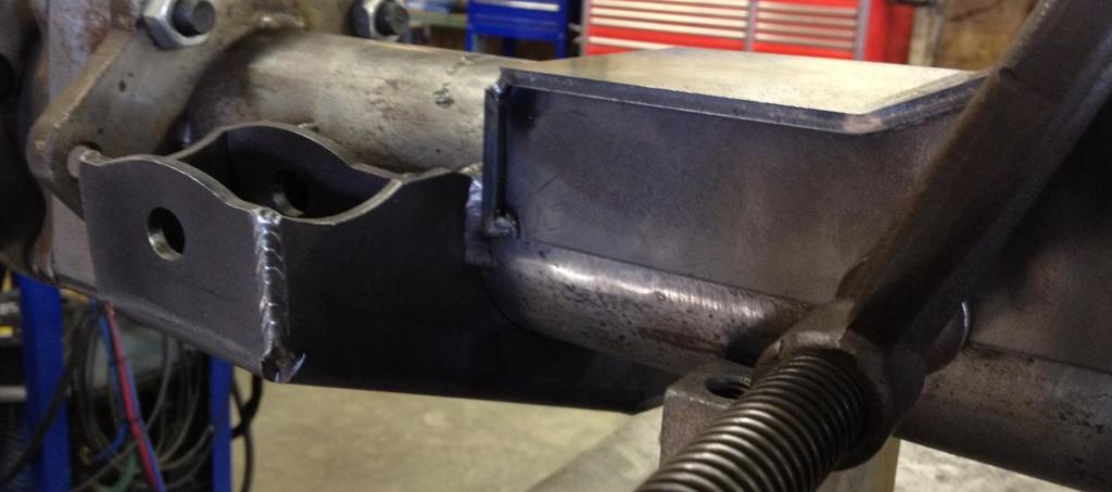
5 3. Trim to fit axle housing 3.1) With the axle on jack stands or some sort of stand, set the pinion angle to your desired angle. I recommend 6 degrees of pinion angle to match the recommended transmission angle. 3.2) Position the bracket assembly on the axle housing. Measure side to side to center the 1132 bracket assembly to the axle housing. The top of the 1132 bracket should be level and the back should be vertical at your desired pinion angle. You will need to trim the back plate, -02 to fit the contour of the top of the diff case. Try to make a precise cut since these sections should be welded. 3.3) The outer ends of the top plate, -01 where the bump pads are located should rest on top of the axle tubes for a 3.5" axle tube. If you are using a smaller tube, there should be a gap equal to half of the difference of tube size from 3.5. For example, a 3" axle tube should have a 1/4" gap. Put shims equal to the gap thickness there to help position the truss assembly. For smaller than 3.5" axle tubes, make a spacer that fills the gap between the tub the top plate so that the top plate doesn't dent from the air bump. 5

6 3.4) After the bracket assembly is trimmed and correctly positioned, install and tack weld the front plates, -03. The over lab should be the same as the back of the truss assembly. 3/16 for a 3.5" tube, refer to the chart above for smaller tube sizes. Go ahead tack weld the front plates to the truss assembly, but NOT the tube. 6


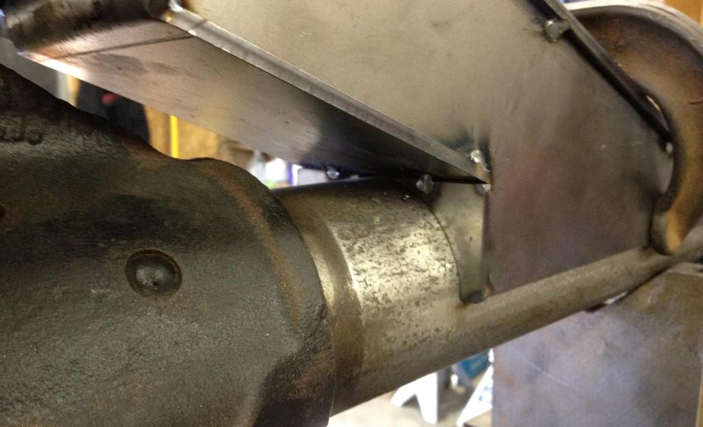
7 3.5) Position and tack weld the end caps, -08. Tack weld them to the 1132 truss assembly and NOT the axle tube. The end caps should hang over the front and back plates by the same overlap amount as the top plate. 7
8 8

9 4. Install inner top plate Install and tack weld the -07 inner top plate to the truss assembly. The height is not critical, just position it with a slight clearance to the top of the diff. You may even cut an opening in the inner top plate to fit around part of the top of the diff housing to get the inner plate as low as possible. If the diff is too large, you may have to leave this top plate out. 9

10 5. Trim Front Plate 5.1) Install and trim the front plate, -07. Try to make it a close fit to the diff housing as you should weld the front plate to the diff housing. 6. Weld the truss assembly 6.1) Remove the truss assembly 6.2) Weld the inner top plate on all 4 sides. 10
 Begin welding the truss assembly. Weld the truss assembly complete first, then weld the truss to the axle tube and housing last.")

11 6.3) Reposition the truss assembly on the axle housing. Center the truss assembly and set the angle. Tack weld the truss in a couple of places to the axle tube. 6.4) Begin welding the truss assembly. Weld the truss assembly complete first, then weld the truss to the axle tube and housing last. Start in the middle at the top and work your way outward, alternating front to back and side to side. Weld in 3" increments following the weld sequence below. Put a tack weld every 3" so you know where to stop your weld. When you weld a section on the front, immediately weld the same section on the back or vise versa, then move to the other side of the diff. 11

12 6.5) Let the truss cool before you weld to the axle housing. 6.6) Weld the truss to the axle housing, weld to the axle tubes in 2-3" increments alternating front to back and side to side. Again, when you weld a section on the front, immediately weld the same section on the back or vise versa, then move to the other side of the diff. Weld the end caps to the axle tube, and weld the top to the diff housing. 12
Make a Safe. Description. Lesson Objectives. Assumptions. Terminology
 Youth Explore Trades Skills Make a Safe Description Welding is a vast area in the metalworking field and a widely used joining process for metal. In this activity plan students will learn how to MIG weld
INSTALLATION MANUAL IOWA MOLD TOOLING CO., INC. BOX 189, GARNER, IA MANUAL PART NUMBER:
 PARTS-1 Model 24562/28562 Crane INSTALLATION MANUAL IOWA MOLD TOOLING CO., INC. BOX 189, GARNER, IA 50438-0189 641-923-3711 MANUAL PART NUMBER: 99903701 Iowa Mold Tooling Co., Inc. is an Oshkosh Truck
Installation Instructions Universal Crossmember Kit - 60 Track Width BEFORE Measure Twice, Weld Once! II
 Installation Instructions Universal Crossmember Kit - 60 Track Width Please read these instructions completely BEFORE starting your installation. Remember the basic rule for a successful installation:
XJ Coil Conversion Rear 4 Link Instructions
 Parts Checklist: Iron Rock Logo Decal 10001 (2) Rock-Link Decal 13287 (2) ironrockoffroad.com Decal (1) LCA/UCA Mounting Subframe 91162 (1) Shock crossmember 91173 (1) Shock crossmember spacer 91178 (2)
Please read the instructions completely BEFORE starting this project.
 Please read the instructions completely BEFORE starting this project. Rhodes Race Cars 8-Point Roll Bars are not designed for use in vehicles where the stock floor has been removed. Check your sanctioning
Place the vehicle on a hard level surface and use an appropriate jack and jack stands to raise the vehicle of the ground.
 1937-1939 Chevy Truck Rear Air Bag 4 - Link Kit Installation Instructions 1-866-925-1101 www.totalcostinvolved.com CHECK ALL PARTS INCLUDED IN THIS KIT TO THE PARTS LIST BEFORE INSTALLATING OF THE KIT.
Please read the instructions completely BEFORE starting this project.
 Please read the instructions completely BEFORE starting this project. Rhodes Race Cars 10 Point Roll Cages are not designed for use in vehicles where the stock floor has been removed. Check your sanctioning
ASSEMBLY INSTRUCTIONS FOR MAR-K BEDSIDES AND GM FLUSH TAILGATE WITH HANDLE
 ASSEMBLY INSTRUCTIONS FOR MAR-K BEDSIDES AND 41-53 GM FLUSH TAILGATE WITH HANDLE Build the box assembly according to the MAR-K assembly instructions. When installing the tailgate and latching mechanisms
1949 to 1954 Chevrolet Dual Master Cylinder Conversion
 1949 to 1954 Chevrolet Dual Master Cylinder Conversion This document is a one stop shop to getting your brake system updated on your old Chevy. Whether you re going with a disc conversion or just sticking
8030 Synergy Jeep JK Rear Long Arm Frame Brackets
 General Notes: SYNERGY MFG. 870 INDUSTRIAL WAY, SAN LUIS OBISPO, CA (805) 242-0397 8030 Synergy Jeep JK Rear Long Arm Frame Brackets These instructions are also available on our website; www.synergymfg.com.
Installation Instructions
 FORD 20K Industry Standard Rail Custom Mounting Kit #2738 Gross Trailer Weight (Maximum)...20,000 lbs. Vertical Load Weight (Max. Pin Weight)...5,000 lbs. SYSTEM TOW CAPACITY Please note, in order to determine
Installation Instructions
 DODGE 16K Industry Standard Rail Custom Mounting Kit #2728 Gross Trailer Weight (Maximum)...16,000 lbs. Vertical Load Weight (Max. Pin Weight)...4,000 lbs. SYSTEM TOW CAPACITY Please note, in order to
INSTALLATION INSTRUCTIONS 10-POINT ROLL CAGE. Please read the instructions completely BEFORE starting this project.
 INSTALLATION INSTRUCTIONS 10-POINT ROLL CAGE Please read the instructions completely BEFORE starting this project. Competition Engineering 10-Point Roll Cages are not designed for use in vehicles where
How We Installed Our 3-Link Banana Bracket:
 How We Installed Our 3-Link Banana Bracket: General Description To avoid failure of your 3-link banana bracket, you will need to pay special attention to the installation. The clamp-on feature of the design
INSTALLATION INSTRUCTIONS 8554 DODGE TRACK BAR CONVERSION BRACKET
 SYNERGY MFG. 870 INDUSTRIAL WAY, SAN LUIS OBISPO, CA (805) 242-0397 INSTALLATION INSTRUCTIONS 8554 DODGE TRACK BAR CONVERSION BRACKET Version 2.0 GENERAL NOTES: These instructions are also available on
Important Note. Tools Required: Welder capable of fully welding 10 GA.135 steel
 INSTALLATION INSTRUCTIONS Frame Reinforcement Kit 11100 (Patent Pending) 1968-72 GM A-Body Coupe/Sedan Read Instructions FULLY before starting Installation Important Note Installation of this kit requires
Clayton Off Road COR COR COR
 Clayton Off Road COR-4806011 COR-4806021 COR-4806031 JEEP GRAND CHEROKEE WJ LONG ARM UPGRADE KITS (1999-2004 WJ) NOTES: This product requires general welding, fabrication and automotive mechanic skills.
Part# C3135/C Up Challenger 8-Point Roll Bar
 Part# C3135/C3150 2008-Up Challenger 8-Point Roll Bar Installation Instructions Please read the instructions completely BEFORE starting this project. Competition Engineering 8-Point Roll Bars are not designed
INDEPENDENT FRONT SUSPENSION SWAP
 INDEPENDENT FRONT SUSPENSION SWAP 20 PHOTOS In this article we will show how to change out the old frame/front suspension of your 49, 50, and 51 Mercury / Ford to a new IFS unit. This high tech front suspension
INSTALLATION INSTRUCTIONS 8-POINT ROLL BAR (TRUCK) Please read the instructions completely BEFORE starting this project.
 Please read the instructions completely BEFORE starting this project.") INSTALLATION INSTRUCTIONS 8-POINT ROLL BAR (TRUCK) Please read the instructions completely BEFORE starting this project. Competition Engineering 8-Point Roll Bars are not designed for use in vehicles where
INSTALLATION INSTRUCTIONS 8-POINT ROLL BAR (TRUCK) Please read the instructions completely BEFORE starting this project. Competition Engineering 8-Point Roll Bars are not designed for use in vehicles where
INSTALLATION INSTRUCTIONS 2008-up Challenger 10-POINT ROLL CAGE C3235 / C3285. Please read the instructions completely BEFORE starting this project.
 INSTALLATION INSTRUCTIONS 2008-up Challenger 10-POINT ROLL CAGE C3235 / C3285 Please read the instructions completely BEFORE starting this project. Competition Engineering 10-Point Roll Cages are not designed
RACER TECH COMMANDER HD TIE ROD INSTALLATION
 RACER TECH COMMANDER HD TIE ROD INSTALLATION NOTE: These instructions are a universal explanation of how to install our HD Tie Rods. All kits are identical for all inner joints and nearly identical for
Installation Instructions
 CHEVY / GMC 20K Industry Standard Rail Custom Mounting Kit #2724 Gross Trailer Weight (Maximum)...20,000 lbs. Vertical Load Weight (Max. Pin Weight)...5,000 lbs. SYSTEM TOW CAPACITY Please note, in order
Important Note. Tools Required: Welder capable of fully welding 10 GA.135 steel
 INSTALLATION INSTRUCTIONS Frame Reinforcement Kit 11102 (Patent Pending) 1964-67 GM A-Body Coupe/2dr Sedan Read Instructions FULLY before starting Installation Important Note Installation of this kit requires
Make a Portable Hibachi
 Metal Work Description The purpose of this activity plan is to introduce students to the metal shop through a practical activity. Students will gain valuable knowledge in using power tools and equipment
Detroit Speed, Inc. Heavy Duty Leaf Spring Pocket Kit Camaro/Firebird P/N:
 Detroit Speed, Inc. Heavy Duty Leaf Spring Pocket Kit 1967-69 Camaro/Firebird P/N: 040110 Thank you for purchasing the Detroit Speed Inc., Heavy Duty Leaf Spring Pocket Kit for your 1967-69 Camaro/Firebird.
Installation Instructions
 TOYOTA 16K Industry Standard Rail Custom Mounting Kit #2748 Gross Trailer Weight (Maximum)...16,000 lbs. Vertical Load Weight (Max. Pin Weight)...4,000 lbs. SYSTEM TOW CAPACITY Please note, in order to
WPS crew Doors Installation instructions
 WPS-132-133 crew Doors Installation instructions ORDER OF INSTALLATION FOR A COMPLETE ENCLOSURE OF A CREW WPS (Weather Protection System) IS AS FOLLOWS: 1. Heater 2. Rear Thresholds - Right Hand & Left
Metal Shapers Forums and Tech Rodding Roundtable Home Forums Events Members Webring Tech Merchandise Contact Chat Services Links Want Ads Advertising
 Metal Shapers Forums and Tech Home Forums Members Webring Tech Contact Chat Services On the following pages your will find detailed instructions on the parts needed and assembly instructions for a 12"
Ford Ranger / Bronco II Set Part # Rev B 5-04
 Ford Ranger / Bronco II Set Part # 21008 Rev B 5-04 Step 1: Prior to Installation: A) Fit: Verify the fit of the flares to vehicle. (Some filing, sanding, or cutting may be necessary to ensure proper fit).
FORWARD FUSELAGE SIDES & REAR TOP SKINS
 FORWARD FUSELAGE SIDES & REAR TOP SKINS WORK REPORT Step No. Check Parts / Tools Qty Preparations. 1 [ ] 6F5-3 Upper Front Longerons 2 2 [ ] 6F5-5 Heel Support 1 3 [ ] 6F5-2 Front Floor Skin 1 3 [ ] Firewall
Installation Instructions Kit, Base Rail Bracket Part # 31413
 Installation Instructions Kit, Base Rail Bracket Part # 31413 Dealer / Installer: Provide a copy of these Instructions to the end user of this product. These Instructions provide important operating and
Installation Instructions
 CHEVY / GMC 16K Industry Standard Rail Custom Mounting Kit #2730 Gross Trailer Weight (Maximum)...16,000 lbs. Vertical Load Weight (Max. Pin Weight)...4,000 lbs. SYSTEM TOW CAPACITY Please note, in order
8561 / 8569 DODGE AAM FRONT AXLE C-GUSSET KIT
 SYNERGY MFG. 870 INDUSTRIAL WAY, SAN LUIS OBISPO, CA (805) 242-0397 8561 / 8569 DODGE AAM FRONT AXLE C-GUSSET KIT GENERAL NOTES: These instructions are also available on our website; www.synergymfg.com.
Assembly Instructions 10 X 10 Aluminum Roof Support
 Assembly Instructions 10 X 10 Aluminum Roof Support Aluminum Roof Support Bolt Package 16-5/16 X 2 ¼ SS Bolt 24-5/16 X 1 SS Bolt 40-5/16 SS Nylon Lock Nuts 16-5/16 SS Flat Washers 28-4 ½ Wood Screws 36-1
TUBULAR FRONT END KIT INSTALLATION INSTRUCTIONS MUSTANG
 TUBULAR FRONT END KIT INSTALLATION INSTRUCTIONS 1979 2004 MUSTANG Pre-Installation Notes & Recommendations: Before disassembly, remove anything within the engine bay that can be removed; this will give
Detroit Speed, Inc. Heavy Duty Leaf Spring Pocket Kit X-Body P/N:
 Detroit Speed, Inc. Heavy Duty Leaf Spring Pocket Kit 1968-74 X-Body P/N: 040111 Thank you for purchasing the Detroit Speed Inc., Heavy Duty Leaf Spring Pocket Kit for your 1968-74 X-Body. The DSE Leaf
Make a Welded Die. Description. Lesson Objectives. Assumptions. Terminology
 Description Welders are required to work with many other metalworking trades. To be successful as a welder, one must have an understanding of many other metalworking skill sets and an understanding of
INSTALL INSTRUCTIONS: FRAME REPAIR KIT
 INSTALL OF FRAME REPAIR KIT (523-203) Ford Ranger 2004 1993 General Tech Tips: Disconnect and Remove Battery Remove fuel tank and clamp, or disconnect fuel lines. Double check for leaking fuel. Ensure
Set Part # Rev
 Set Part # 21007 Rev-3 06-06-11 Step 1: Prior to Installation: A) Bushwacker only approves installing the flares according to these written instructions with the hardware provided. WARNING: Failure to
JK Crusher Corners. *Includes ONE of the Hardware Kits (not both)
") INSTALLATION INSTRUCTIONS INST-18-05-020_A JK Crusher Corners IMPORTANT: Thank you for purchasing this Poison Spyder product. Please read through this entire document before proceeding with installation.
INSTALLATION INSTRUCTIONS INST-18-05-020_A JK Crusher Corners IMPORTANT: Thank you for purchasing this Poison Spyder product. Please read through this entire document before proceeding with installation.
Installation Instructions
 CHEVY / GMC 20K Industry Standard Rail Custom Mounting Kit #2724 Gross Trailer Weight (Maximum)...20,000 lbs. Vertical Load Weight (Max. Pin Weight)...5,000 lbs. SYSTEM TOW CAPACITY Please note, in order
69-70 Floor Pan Fixes
 Approx Time Needed For Completion: Approx 20 hrs Equipment Needed: - Work stand or table for initial cutting, welding and working - Cooper scraps for backing during welding (prevents blow through when
FORD #2228. Gross Trailer Weight (Maximum)...24,000 lbs. Vertical Load Weight (Max. Pin Weight)...6,000 lbs. SYSTEM TOW CAPACITY
...24,000 lbs. Vertical Load Weight (Max. Pin Weight)...6,000 lbs. SYSTEM TOW CAPACITY") FORD 24K Industry Standard Rail Heavy Duty Custom Mounting Kit #2228 Gross Trailer Weight (Maximum)...24,000 lbs. Vertical Load Weight (Max. Pin Weight)...6,000 lbs. SYSTEM TOW CAPACITY Please note, in
FORD 24K Industry Standard Rail Heavy Duty Custom Mounting Kit #2228 Gross Trailer Weight (Maximum)...24,000 lbs. Vertical Load Weight (Max. Pin Weight)...6,000 lbs. SYSTEM TOW CAPACITY Please note, in
TOOL LIST FOR TAILGATE HIDDEN LATCH & LINK ASSY FOR FORD FLARESIDE TRUCKS
 TOOL LIST FOR TAILGATE HIDDEN LATCH & LINK ASSY FOR 53-87 FORD FLARESIDE TRUCKS Vise Grip Clamps C-clamps Sharpie Marker Ball Peen Hammer Center Punch 3/8 or 1/2 Drill 5/32, 7/32, 9/32, and 3/8 Drill Bits
2013 and up Dodge 2500/ Stage Rear Install Instructions
 D2RX-23-13 2686 Highway 92 - Oskaloosa, IA 52577 phone: 641.673.0468 - fax: 641.673.4168 www.kelderman.com 2013 and up Dodge 2500/3500 2-Stage Rear Install Instructions 1. Remove the spare tire. 2. Remove
INSTALLATION INSTRUCTIONS FOR & Chevy CUT OUT FLARE
 40009 7/10/03 REV-A INSTALLATION INSTRUCTIONS FOR 40009 & 40010 Chevy CUT OUT FLARE TOOLS REQUIRED FOR INSTALLATION: Drill Motor Pop Rivet Gun Flat File Hair Dryer or Heat Gun Sawzall Jack and Jack Stands
k 5356 PINE AVE FRESNO, CA USA TOLL FREE: 877.4X4.TOYS WORLDWIDE:
 tacoma front shackle kit 110821-1-k kit contents 5356 PINE AVE FRESNO, CA 93727 USA TOLL FREE: 877.4X4.TOYS WORLDWIDE: 559.252.4950 WWW.TRAIL-GEAR.COM recommended tools Loctite Cutoff Wheel Welder Grinder
Fairlane Front Suspension Install Sheet
 1966-1967 Fairlane Front Suspension Install Sheet 1-866-925-1101 Read and understand these instructions before starting any work! 1966-1967 Fairlane Front Suspension Installation Instructions Thank you
JK Rear Crusher Flares
 INSTALLATION INSTRUCTIONS INST-17-05-010_A JK Rear Crusher Flares IMPORTANT: Thank you for purchasing this Poison Spyder product. Please read through this entire document before proceeding with installation.
CUT OUT FLARES INSTALLATION INSTRUCTIONS FOR 20017, 20018, F100-F150 F250-F350 P.U. & BRONCO CUT OUTS
 20017 04/22/03 REV-A CUT OUT FLARES INSTALLATION INSTRUCTIONS FOR 20017, 20018, F100-F150 F250-F350 P.U. & BRONCO CUT OUTS Tools Required for Installation: (A) 3/16 Drill Bit (B) Pop-Rivet Gun (C) Air
6625 WEST WILSHIRE BLVD. OKLAHOMA CITY, OK (405) FAX (405)
 FAX (405)") INSTALLATION INSTRUCTIONS FOR BEDSIDE INNER REPAIR PANELS 67-72 GM FLEETSIDES This instruction illustrates the removal and replacement of the often rusted and damaged lower inner flanges on the 1967-1972
INSTALLATION INSTRUCTIONS FOR BEDSIDE INNER REPAIR PANELS 67-72 GM FLEETSIDES This instruction illustrates the removal and replacement of the often rusted and damaged lower inner flanges on the 1967-1972
Included in Hardware Kit. Jeep Cut-Out Fender Flare Set of 4 Set Part # Rev STEP 1 PRIOR TO INSTALLATION
 Jeep Cut-Out Fender Flare Set of 4 Set Part #10926-07 Rev-01 09-11-12 STEP 1 PRIOR TO INSTALLATION A) Bushwacker only approves installing the flares according to these written instructions with the hardware
Cut-Out Fender Flares Rear Pair. Jeep. Included in Hardware Kit:
 Jeep Cut-Out Fender Flares Rear Pair STEP 1 PRIOR TO INSTALLATION A) Bushwacker only approves installing the fl ares according to these written instructions with the hardware provided. WARNING: Failure
Installation Instructions
 FORD 20K Industry Standard Rail Custom Mounting Kit #2760 Gross Trailer Weight (Maximum)...20,000 lbs. Vertical Load Weight (Max. Pin Weight)...5,000 lbs. SYSTEM TOW CAPACITY Please note, in order to determine
Installation instructions for Standard front steer I.F.S.
 Installation instructions for Standard front steer I.F.S. Scotts Hotrods 3421 Galaxy Place Oxnard CA 93030 (805) 485 0382 Rev: A Installation Manual for Standard front steer IFS Please note a few things
MOR/ryde Steer Axle Suspension System
 MOR/ryde Steer Axle Suspension System (Double Eye Leaf Spring) Steer Axle Installation Instructions MOR/ryde International 1966 Moyer Avenue Elkhart, IN 46516 574-293-1581 www.morryde.com SRL153-001 REV.
Installation Instructions
 CHEVY / GMC 24K Industry Standard Rail Heavy Duty Custom Mounting Kit #2226 Gross Trailer Weight (Maximum)...24,000 lbs. Vertical Load Weight (Max. Pin Weight)...6,000 lbs. SYSTEM TOW CAPACITY Please note,
CENTER WING SECTION (CWS) WORK REPORT
 WORK REPORT") CENTER WING SECTION (CWS) WORK REPORT No. Check Parts / Description Qty PHASE 1: Preparations 1 [ ] 6V1-3 Rear ribs 2R & 2L 1 [ ] L Angle 6 2 [ ] 6V2-1 Rear Ribs.032 2R & 2L 2 [ ] 6V5-1 Gear Rib Doubler
CENTER WING SECTION (CWS) WORK REPORT No. Check Parts / Description Qty PHASE 1: Preparations 1 [ ] 6V1-3 Rear ribs 2R & 2L 1 [ ] L Angle 6 2 [ ] 6V2-1 Rear Ribs.032 2R & 2L 2 [ ] 6V5-1 Gear Rib Doubler
CRYSTEEL S. this manual must be included with the vehicle after completing the installation.
 Website: www.tbei.com E-mail: sales@tbei.com CRYSTEEL S Grain Tipper mounting and operating instructions this manual must be included with the vehicle after completing the installation. Web Site E-Mail
1. The saddle is located on the underside of the crossmember in the front of the frame, just under the engine oil pan.
 FRAME SADDLE REPAIR Full-framed GM musclecars have an engine cradle, or saddle, that is almost always damaged from floor jack abuse. Located squarely in the middle of the frame beneath the engine, the
Plans & Materials List for Handwashing Station
 Plans & Materials List for Handwashing Station Required Tools Arc Welder (mig or stick) Chop or metal band saw Grinder (bench and/or handheld) 3/8" Drill 1/8", 1/4", 5/16" Drill Bits Copper Pipe Cutter
RLP Flat Track Hardware sliding door hardware/ barn door track
 Page 1 of 9 Installation Suggestions for: RLP Flat Track Hardware sliding door hardware/ barn door track Read these instructions to end before starting installation or ordering hardware. Reclaimed Lumber
How to Make a Wedding Band 52 to 66 K, XL & XLH By the OSKRG vs.2
 How to Make a Wedding Band 52 to 66 K, XL & XLH By the OSKRG vs.2 Tools Needed: Large Vise Torch Welder Large Channel locks Drill Motor For a 52 through 55 K Model: o A 5/16 x 24 Tap & 17/64 bit For a
1964 ½ Mustang Front Suspension Installation Instructions
 1964 ½ - 1970 Mustang Front Suspension Installation Instructions 1-800-984-6259 www.totalcostinvolved.com All engine installations with this front end will require a rear sump oil pan. 289-302 Small Block
INSTALLING T400 LOAD SENSORS
 INSTALLING T400 LOAD SENSORS The above illustrations represent the proper arrangement of Model T400 Load Sensor kit parts using either the Drill and Tap method or the Weld method. A proper installation
Installation Instructions
 DODGE RAM 2500 20K Industry Standard SuperRail Custom Mounting Kit #2336 Gross Trailer Weight (Maximum)...20,000 lbs. Vertical Load Weight (Max. Pin Weight)...5,000 lbs. SYSTEM TOW CAPACITY Please note,
Page 1 of 12 GENERAL INSTRUCTIONS KHJKK Installation
 Page 1 of 12 KHJKK PICTURE ABOVE IS THE UNIVERSAL KIT; YOUR KIT MAY BE DIFFERENT. THIS KIT INCLUDES: 8 M8-1.25X30MM BOLTS WITH WASHERS 8 M8-1.25X40MM BOLTS WITH WASHERS 2 PINS RIGHT AND LEFT HINGE ASSEMBLY
Build a Drill Press Vise
 Youth Explore Trades Skills Introduction This activity plan will develop the student s machining and metalworking skills as they fabricate a multi-piece steel vise. The project will encompass basic lathe
Ford Pick Up Rear leaf Spring Kit Installation Instructions
 1948-1956 Ford Pick Up Rear leaf Spring Kit Installation Instructions 1-800-984-6259 www.totalcostinvolved.com Parts 48 inch leaf (2) springs (4) U-bolts 3/8-24 x l 1/4bolts (16) & nuts (2) 1/2-20 x 4
INSTALLATION INSTRUCTIONS
 CJ FULL WIDTH CONVERSION KIT The Poison Spyder Customs Full Width Axle Conversion Kit is designed to mount full width axle assemblies underneath 76 to 86 Jeep CJ s (CJ-5, CJ-7 & CJ-8). The kit is designed
CEB Main Frame: Assemble U-Channel
 CEB Main Frame: Assemble U-Channel Assemble the U-channel on your Compressed Earth Brick Press. Written By: Dozuki System 2017 opensourceecology.dozuki.com Page 1 of 11 INTRODUCTION Sketchup ModelAdditional
OTHER TOOLS MAY BE NEEDED DEPENDING ON YOUR VEHICLE.
 THIS KIT INCLUDES: 16 M8-1.25X40MM BOLTS WITH WASHERS 2 SHOCKS 720 PSI RIGHT AND LEFT HINGE ASSEMBLY 2 SHOULDER BOLTS 2 PINS TOOLS REQUIRED FOR INSTALLATION: AIR RACHET, GRINDER AND CUTTER. 10MM, 11MM,
YJ DeFenders. These installation instructions apply to the following Poison Spyder products:
 INSTALLATION INSTRUCTIONS INST-13-02-070_A YJ DeFenders IMPORTANT: Thank you for purchasing this Poison Spyder product. Please read through this entire document before proceeding with installation. If
Installation Instructions Kit, Base Rail Bracket Part # 31413
 Installation Instructions Kit, Base Rail Bracket Part # 31413 Dealer / Installer: End User: Provide a copy of these Instructions to the end user of this product. These Instructions provide important operating
FIRST TEAM SPORTS, INC.
 FIRST TEAM SPORTS, INC. INVADER EZ-CRANK PORTABLE BASKETBALL GOAL ASSEMBLY INSTRUCTIONS Revised - 08/04/10 BILL OF MATERIALS (1) BASE TANK (1) BACKBOARD MOUNT (2) 5/16 X ¾ HEX BOLT (1) LOWER POST (2) SPRING
Jeep. Cut-Out Fender Flares Set of 4. Included in Hardware Kit: Set Part # Rev-8 06/29/16 STEP 1 PRIOR TO INSTALLATION
 STEP 1 PRIOR TO INSTALLATION A) Bushwacker only approves installing the flares according to these written instructions with the hardware provided. WARNING: Failure to install according to these instructions
i sburgh COMPACT BENDER ASSEMBLY INSTRUCTIONS & PROJECT IDEAS Rev 08/00
 i sburgh COMPACT BENDER 31980 ASSEMBLY INSTRUCTIONS & PROJECT IDEAS 2000 Rev 08/00 THANK YOU for choosing a HARBOR FREIGHT TOOLS product. For future reference, please complete the owner s record below:
USE THE PARTS LIST BELOW TO MAKE SURE YOUR KIT IS COMPLETE BEFORE INSTALLATION. IF ANY PIECES ARE MISSING, PLEASE CONTACT:
 1967-1969 Cougar Custom IFS Install Sheet Tech Line: 1-855-693-1259 www.totalcostinvolved.com Read and understand these instructions before starting any work! USE THE PARTS LIST BELOW TO MAKE SURE YOUR
Installation for Full Size Polaris Ranger Crew Doors
 Installation for Full Size Polaris Ranger Crew Doors Order of Installation: Heater Doors Wiper on to Windshield Windshield Top & Back Panel Note: Most of the steps in these instructions need to be repeated
Eraser Conveyor Belt Cleaning System IWARNING Always obey all applicable safety rules. Be sure all power to the conveyor has been disconnected and con
 INSTALLATION GUIDE LIB-CP-REA-03-01 Rev. 10 Eraser Conveyor Belt Cleaning System ARGONICS Eraser Conveyor Belt Cleaning System IWARNING Always obey all applicable safety rules. Be sure all power to the
Haukaas Bale Rack Kit
 Page 1 Haukaas Bale Rack Kit For hauling large round bales "Pipe Style". C D Pocket Reinforcement Plates 10" 11" A: Pocket Side Plate B: Pocket Top Plate C: Side Stake D: End Stake E: Floor Plate B A F:
Installation Manual Flat Track Series
 Manual Flat Track Series Contents Safety...1 Parts...2 Hardware.......................................... 2 Tools Required..................................... 4.............................................
00108/00110 INSTRUCTION MANUAL
 00108/00110 INSTRUCTION MANUAL Removable and Adjustable Mudflap System IMPORTANT! Exhaust Systems Note: Any modifications to the factory installed exhaust system may void your manufacturer s warranty.
RLP Mini Low Profile V Track Hardware sliding door hardware/ barn door track
 Page 1 of 9 Installation Suggestions for: RLP Mini Low Profile V Track Hardware sliding door hardware/ barn door track Read these instructions to end before starting installation or ordering hardware.
Please read these instructions all the way through before starting, since the order of work is important.
 Due to the many differing vehicles to which Safety Devices roll cages can be fitted, these instructions are of a general nature and not specific to your vehicle. Important Note Roll bars and/or front cages
1984 to ZX (Z31) Rear Camber Modification Gary Molitor, March 1, 2009
 Rear Camber Modification Gary Molitor, March 1, 2009") 1984 to 1989 300ZX (Z31) Rear Camber Modification Gary Molitor, March 1, 2009 Step 1: Bushing Removal After removal of the rear suspension and disassembly of all the parts, the first thing I did was remove
1984 to 1989 300ZX (Z31) Rear Camber Modification Gary Molitor, March 1, 2009 Step 1: Bushing Removal After removal of the rear suspension and disassembly of all the parts, the first thing I did was remove
MIG / TIG / PLASMA WELDING CART
 MIG / TIG / PLASMA WELDING CART INSTRUCTIONS Part #11616 This welding cart was designed by The Eastwood Company to make storage, accessibility, and maneuverability of your welders easier than ever before.
E4-WM5-Y525A00 MOUNTING INSTRUCTION
 RAM 2500/3500 4WD B8 5100 (Dual Steering Damper Kit) The installation of these steering dampers must be performed only by experienced and qualified personnel. Read and follow the installation instructions
RZR 900 Trail / XC / 900 / 1000 S/4
 RZR 900 Trail / XC / 900 / 1000 S/4 Polaris RZR 900 Trail - Trail Fox Edition - XC - 900 S/4-1000 S 2015+ Part #: 5601513, 5601514 Rev. 031417 491 W. Garfield Ave., Coldwater, MI 49036. Phone: 517-278-7768
UNIVERSAL UNDERCARRIAGE MOUNTING INSTRUCTIONS (PART NO. LTA07667B)
") BOSS PRODUCTS A Division of Northern Star Industries, Inc. P.O. Box 787 Iron Mountain MI 49801-0787 www.bossplow.com UNIVERSAL UNDERCARRIAGE MOUNTING INSTRUCTIONS (PART NO. LTA07667B) DRIVEN TO BE THE
BOSS PRODUCTS A Division of Northern Star Industries, Inc. P.O. Box 787 Iron Mountain MI 49801-0787 www.bossplow.com UNIVERSAL UNDERCARRIAGE MOUNTING INSTRUCTIONS (PART NO. LTA07667B) DRIVEN TO BE THE
GMC Cut-Out Fender Flares Set of 4
 GMC Cut-Out Fender Flares Set of 4 STEP 1 PRIOR TO INSTALLATION A) Bushwacker only approves installing the fl ares according to these written instructions with the hardware provided. WARNING: Failure to
For installation assistance, contact SARGENT at DOORS SHOWN HERE SWING IN FOR ILLUSTRATION PURPOSES ONLY.
 SARGENT Installation Instructions for LP8600 x LR8600 & 12-LP8600 x 12-LR8600 Series Low Profile Panic and Fire Exit Devices on Double Egress & Double Doors or LS8600 & 12-LS8600 Low Profile Exit Device
Oxford Stalls Installation Instructions
 Oxford Stalls Installation Instructions RAMM Horse Fencing and Stalls 13150 Airport Hwy. Swanton, OH 43558-9615 1-800-434-8456 Rev. 8/15/17 Before You Start Typical stall sizes are 10 x 10, 12 x 12 or
MM540 Installation Instructions IMPORTANT SAFETY INSTRUCTIONS - SAVE THESE INSTRUCTIONS
 MM50 Installation Instructions IMPORTANT SAFETY INSTRUCTIONS - SAVE THESE INSTRUCTIONS Please read this entire manual before you begin. Do not unpack any contents until you verify all requirements on PAGE.
CHEVY/GMC SuperRail Mounting Kit #3117
 CHEVY/GMC SuperRail Mounting Kit #3117 #3100 SuperGlide (12K) Gross Trailer Weight (Maximum) Vertical Load Weight (Max. Pin Weight) 12,000 lbs. 3,000 lbs. Installation Instructions SPECIFICATIONS Fits
A Portable, Human-Powered Lathe Designed and Built by Scott Lewis Illustrations by David Heim
 Tailstock Toolrest and banjo Drive belt guard Headstock post Headstock spindle Page 1 Metric dimensions Tailstock post Drive belt tensioner Drive belt and flywheel Chair Bicycle pedals, sprockets, and
Installation Instructions for Vista Air Vertically Folding Walls
 Installation Instructions for Vista Air Vertically Folding Walls Use these instructions in conjunction with your shop drawings to see the specifics that are particular to the model you are installing.
SMAW LESSON #1: Initiating and maintaining an arc using the scratch start method
 SMAW LESSON #1: Initiating and maintaining an arc using the scratch start method OBJECTIVE: Upon completion of this lesson the learner will be able to strike and maintain an arc using SMAW on steel plate
All American Mower Blade Sharpener Mulching Blade Model Patent Pending
 All American Mower Blade Sharpener Mulching Blade Model 5000 Patent Pending Revised May 3, 2017 Attaching the guide pin to your grinder: Assembly and Use Locate the guide pin (included with the sharpener)