How to Make a Wedding Band 52 to 66 K, XL & XLH By the OSKRG vs.2
|
|
|
- Marsha Young
- 5 years ago
- Views:
Transcription

1 How to Make a Wedding Band 52 to 66 K, XL & XLH By the OSKRG vs.2 Tools Needed: Large Vise Torch Welder Large Channel locks Drill Motor For a 52 through 55 K Model: o A 5/16 x 24 Tap & 17/64 bit For a 56 through 66 K, XL & XLH: o A 3/8 bit 1 Solid Steel Round Stock Framing Square BFH, Good Size Hammer 2 Good Size Screwdrivers Silver Solder


2 Steps: 1. The rear downtubes measure 1 so you will need a 1 solid steel round stock to form the band around. I used one of the wheel supports from my John Deere 316 mowing deck, it turned out to be 1.


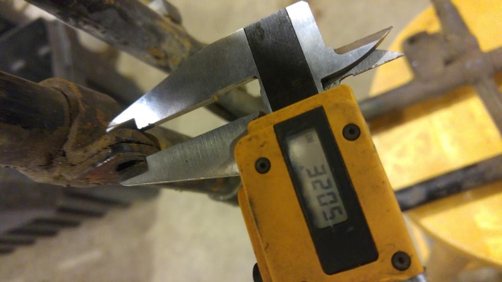
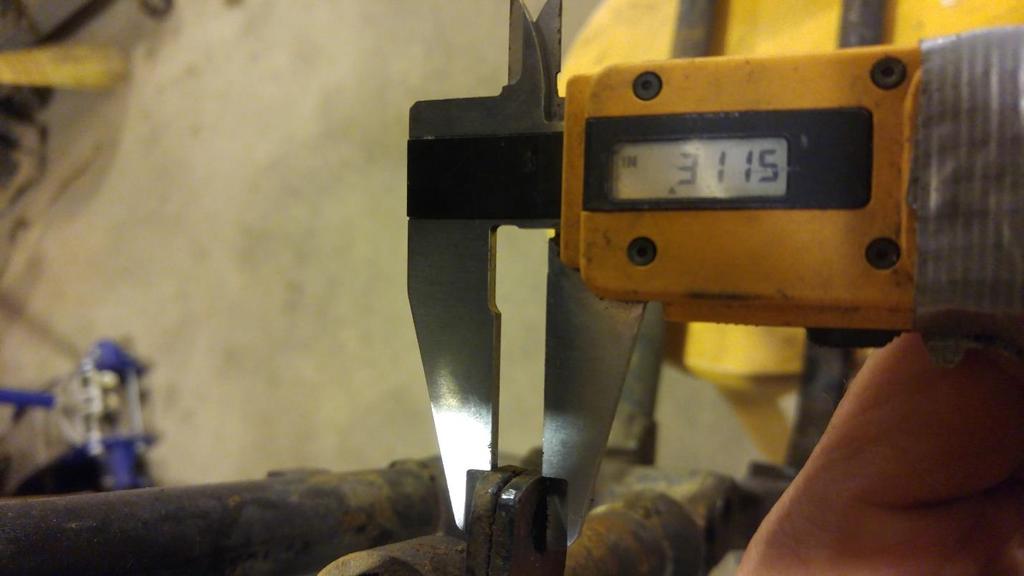
3 2. It was difficult for me to determine the thickness of the steel to use for the wedding band due to rust and paint on the bands and differences in the tightness of the two band halves brought together. My guess is either.134, #10 BWG or.148, #9 B.W.G. steel. It was easy to measure the ¾ width of the bands on bikes. I could not find a source for #9 or #10 B.W.G. cold rolled steel so I bought 24 x 3/4 x 5/32 and had a machinist grind it down for me. I went with.148 this time. Next time I my compromise and split the difference between the #9 & #10 BWG steel and go with.140 #10 AWG.


4 I then cut the stock into three 8 pieces. Easy to measure the ¾. I have measured a number of wedding band thicknesses and have found them to be anywhere from.300 to.330. Again, I believe these differences to be more related to rust, paint and craftsmanship rather than varying steel thickness used.
5


6 3. Tack the steel to your 1 inch solid round stock on one side only. Use your framing square to make sure the band is perpendicular to the solid round form. Once properly lined tack the other side.


7 4. Heat and bend half of the band at a time. You will want to get the steel cherry red hot all the way up to your tack welds and a good 1 from the tacks. 5. As quickly as you can turn off the torch and bend the band half with a large channel locks about 90 degrees. The quicker you can do this after removing the torch the easier it will be and the better it will shape.


8 It is important that the band steel wraps tightly/closely around your solid steel tube. I reheated the steel and while it was red hot used the hammer to bend it into a tighter radius if I noticed spots where it was away from the steel form. After you repeat the process on the other half of the band it should look something like this.


9 6. Place the band into your large vice with it as close to your solid steel round form as possible. Heat cherry red hot both sides of the band where the vice will be squeezing it. You will have to work the torch back and forth on both sides. While applying heat to both sides slowly turn the vice until the vice jaws have completely squeezed together the two halves of the band.


10 Band shown after the squeeze. 7. You will notice a gap where the two halves come together, I like to close this up more.


11 You can do this one half at a time. Using the torch get the area shown under the large chisel red hot, the hotter the better and then using a BFH, a large hammer, whack the chisel right at the base where the two halves come together. Repeat the process on the other half. This should close the gap up some.


12 8. For removing the band from the solid round stock, I carefully ground the welds and then placing the band as shown in the vice I drove the solid stock out. With the weld sufficiently ground this broke the band loose. Then using a grinder or files I dressed the band some to clean it up from the tack welds.


13 Using my.148 thickness steel stock this band at least at this point measured.308 which falls within the spectrum of measurements I ve taken on factory bands. 9. Using several good size screwdrivers or something comparable open up your band to fit it over the downtube. You may need to drive it on with your BFH.


14 10. You will need to clamp in place the band in preparation for welding it in place. You will need to take care in positioning it height wise so that the eventual hole to be installed in the center of it lines up with the lower mounting hole of the oil tank bracket. You will also want to make sure that you have it at the appropriate angle relative to the rear downtube.

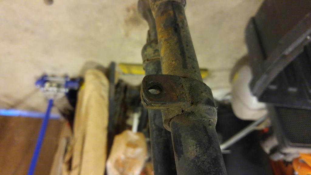
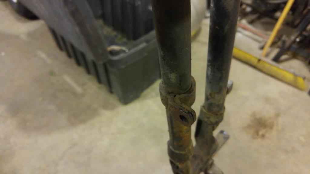
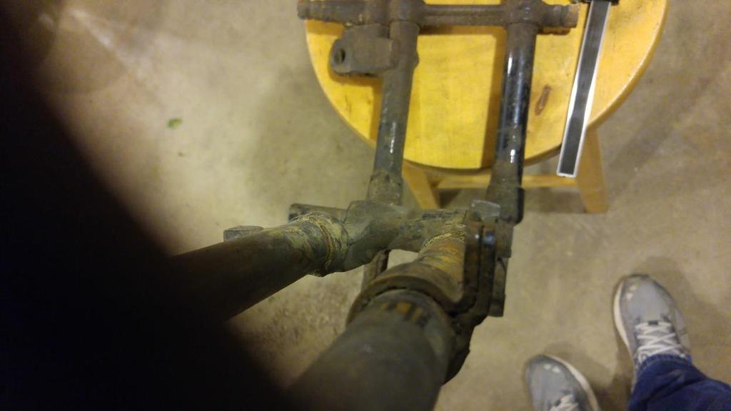
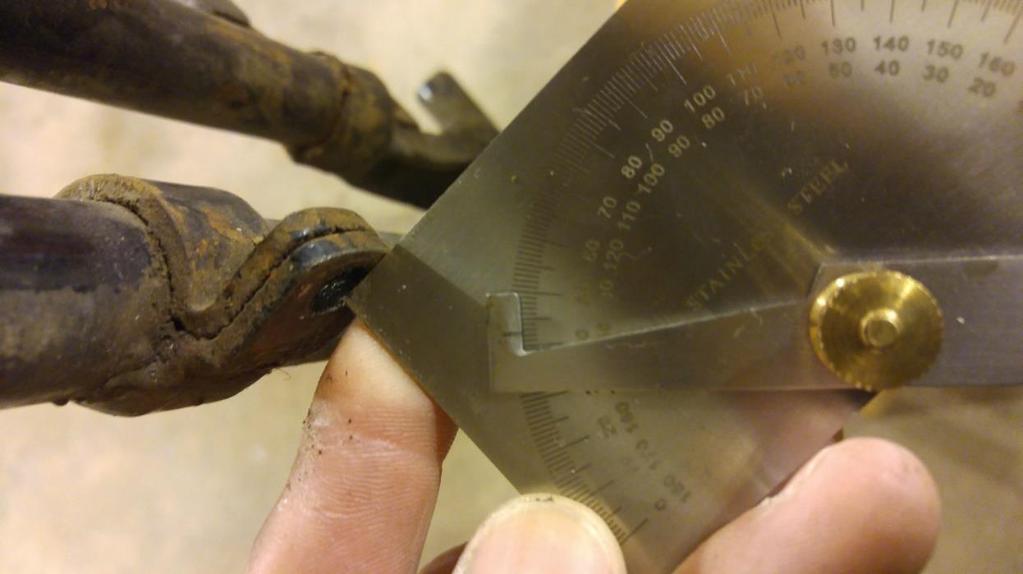
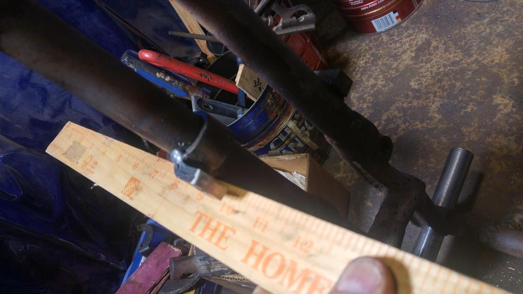
15 For the setting the height I would recommend mounting the oil tank bracket with the two top screws and then positioning the band so that the oil tank brackets bottom screw centers vertically on the band. For setting the angle I have provided a number of pictures showing a factory installed band. If a line parallel to the two rear downtubes was at 6 o clock I would say the band should angle out at about 5:15 to 5:30, this works for the ones I ve done. The yardstick in the following pictures shows what I mean by a parallel line with the rear downtubes.
16
17

18 11. Once you have the band properly positioned weld it (not much is needed if you want to look factory) both on the top and bottom where the two halves come together and meet the downtube. I have seen a variety of welding schemes used, I believe it depended on who was working that day. I have seen additional tacks on some frames in different locations. What I would say is a must however are the two weld where the halves join the frame. These will anchor the band when you heat the band up and bend it into position.


19 12. Not shown in the following picture is the torch heating the two halves of the band up red hot as the channel locks make the final bend. I didn t have enough hands to hold the camera, torch and channel locks for this picture. You will want to have the frame somewhat anchored or wedged because you will be holding the torch in one hand and the channel locks in the other, as you bend the band the frame may try to move on you. Band shown after the bend. What you are shooting for here is for it to be parallel with the frame front to back and if you laid a ruler against the rear downtube facing forward the inside edge of the band should line up with the inside edge of the ruler. r
20


21 13. Cut the band at this point but I would not go shorter then about 1.95 as seen below. Better to be a little bit too long then to short. You will eventually be grinding/filing this edge down some for a finished look.

.")
22 You can see from the examples shown below what the slightly rounded outer edge should look like. For final length, I would go more with the hole position leaving about 3/16 to the front of the hole. 56 through 66 should be an unthreaded hole to accommodate a 5/16 nut and bolt (as shown below with the red downtube on a 56K frame). 52 through 55 require a threaded hole, 5/16 x 24 thread as shown below with this 54 K frame.


23 14. Some bands have a weld on the front edge, others do not. This weld is ground smooth when you shape the front edge.

24 15. Mount the oil tank bracket by the top two bolts and with it secured mark the hole for the wedding band. You may need at this point to find a compromise between the dimensions I have given you and how the hole from the bracket lines up with the band. What I noticed is that most of the oil tank bracket top mounting flanges are bent somewhat from earlier use. This may shift the lower mounting hole towards the front or rear of the band. In addition, the rough length I advised you to cut the band down to will most likely be a little long and interfere with the front edge of the oil tank bracket. Don t bend the oil tank bracket towards the front to clear the rough-cut band, rather mark where the hole should be and grind/file the band to the appropriate length. Your finished hole position should be close to the dimension shown with the ruler in preceding pictures.


25 16. Drill or drill and tap the band.


26 17. Finish dress the front edge.


27 18. The final step if desired is to silver solder the band to the downtube, the factory did this. I used the rod shown below, it worked well. Heat up the band and tube and let the solder flow. As before I couldn t hold the camera, torch and rod at the same time so below I show the heating and after that I show the rod. You ll want to work the rod while heating the band (at least this is the way I do it, bear in mind I m an electrician not a welder/soldering professional).


28 19. Make sure your bracket works.
Hose Hanger Cold Metal Work
 Hose Hanger Cold Metal Work Name: Date: Description: A cold metal project that gives students practice sheering, bending, drilling, and fastening steel. The hose hanger can be used for proper storage of
INSPECTION AND CORRECTION OF BELLHOUSING TO CRANKSHAFT ALIGNMENT
 INSPECTION AND CORRECTION OF BELLHOUSING TO CRANKSHAFT ALIGNMENT BACKGROUND Proper alignment of the transmission input shaft to the crankshaft centerline is required in order to achieve the best results
6625 WEST WILSHIRE BLVD. OKLAHOMA CITY, OK (405) FAX (405)
 FAX (405)") INSTALLATION INSTRUCTIONS FOR BEDSIDE INNER REPAIR PANELS 67-72 GM FLEETSIDES This instruction illustrates the removal and replacement of the often rusted and damaged lower inner flanges on the 1967-1972
INSTALLATION INSTRUCTIONS FOR BEDSIDE INNER REPAIR PANELS 67-72 GM FLEETSIDES This instruction illustrates the removal and replacement of the often rusted and damaged lower inner flanges on the 1967-1972
Make a Safe. Description. Lesson Objectives. Assumptions. Terminology
 Youth Explore Trades Skills Make a Safe Description Welding is a vast area in the metalworking field and a widely used joining process for metal. In this activity plan students will learn how to MIG weld
Battery Terminal Puller
 Battery Terminal Puller Name: Date: Description: Students will be able to construct a Battery Terminal Puller. Students will focus on using cold metal skills, layout skills, and forming the metal into
Important Note. Tools Required: Welder capable of fully welding 10 GA.135 steel
 INSTALLATION INSTRUCTIONS Frame Reinforcement Kit 11100 (Patent Pending) 1968-72 GM A-Body Coupe/Sedan Read Instructions FULLY before starting Installation Important Note Installation of this kit requires
Sheet Metal Brake Plans for a 6' Sheet Metal Brake
 Sheet Metal Brake Plans for a 6' Sheet Metal Brake,1752'8&7,21 Thank you for purchasing the sheet metal brake plans. The plans include a complete list of material needed and easy to follow steps to build
MINI-LATHE QUICK CHANGE TOOL POST
 MINI-LATHE QUICK CHANGE TOOL POST Cutting and assembly details Machinists should familiarize themselves with the contents of this section before jumping in to the drawings. Many details are described here
Important Note. Tools Required: Welder capable of fully welding 10 GA.135 steel
 INSTALLATION INSTRUCTIONS Frame Reinforcement Kit 11102 (Patent Pending) 1964-67 GM A-Body Coupe/2dr Sedan Read Instructions FULLY before starting Installation Important Note Installation of this kit requires
Clocking a TD-04 Turbo Compressor Housing. Appendix A : AWIC Silicone and Tubing Fitting
 Clocking a TD-04 Turbo Compressor Housing Appendix A : AWIC Silicone and Tubing Fitting Revision A: 7-13-2015 Tools: Metric Sockets (10, 12, 14, 17mm) 5mm Hex Key Large Internal Snap Ring Pliers 3/8 Socket
Slide the stock rubber tank mount caps onto the ends of the CS-1 tank mount:
 RYCA CS-1 BODY PARTS INSTALLATION GUIDE [The CS-1 installation guides should be used as supplements to the videos found on our Youtube Channel. There is no strict order to the build process, but it is
Precision Steel Car s 100 T Steel Coil Car
 Precision Steel Car s 100 T Steel Coil Car Precision Steel Car www.precisionsteelcar.com info@precisionsteelcar.com Paul Vernon: (513) 571-5739 Revised 4/30/2009 Contents of Kit Main Tube Side Frame 2
Coil Winder Instructions.
 Page Coil Winder Instructions. Before we can build our wind turbine there are a few tools we need to make. We ll need to make moulds for the magnet rotors and the stator, and we need to make a coil winder.
Travis Bishop. Submitted to: Dr. John Davis. Date: 3 December Course: ETME 310 Section: 004. Lab Topic: Milling Project (Vise)
") Travis Bishop Submitted to: Dr. John Davis Date: 3 December 2012 Course: ETME 310 Section: 004 Lab Topic: Milling Project (Vise) Introduction: Purpose of Experiment: This experiment was conducted to teach
Travis Bishop Submitted to: Dr. John Davis Date: 3 December 2012 Course: ETME 310 Section: 004 Lab Topic: Milling Project (Vise) Introduction: Purpose of Experiment: This experiment was conducted to teach
IBEX 1132 REAR AXLE UCA TRUSS GOAT BUILT IBEX REAR AXLE UPPER CONTROL ARM BRACKET/TRUSS
 GOAT BUILT IBEX REAR AXLE UPPER CONTROL ARM BRACKET/TRUSS Thank you for purchasing Ibex chassis kit components, before starting your build, we recommend that you read through these instructions to familiarize
BEST PRACTICE GUIDE. Socket Bases. Working with Concrete Slabs
 Working with Concrete Slabs When working with concrete slabs the barrier protection can be erected in three ways - with socket bases, adjustable slab edge brackets and multi slab clamps. Socket Bases 1
Rorty No.2 Tube Bender.
 Copyright. This entire Manual is copyrighted to Rorty Design, with all rights reserved. No part may be transferred or copied by any means whatsoever, without the express written permission of Rorty Design.
8030 Synergy Jeep JK Rear Long Arm Frame Brackets
 General Notes: SYNERGY MFG. 870 INDUSTRIAL WAY, SAN LUIS OBISPO, CA (805) 242-0397 8030 Synergy Jeep JK Rear Long Arm Frame Brackets These instructions are also available on our website; www.synergymfg.com.
Please read these instructions all the way through before starting, since the order of work is important.
 Due to the many differing vehicles to which Safety Devices roll cages can be fitted, these instructions are of a general nature and not specific to your vehicle. Important Note Roll bars and/or front cages
INSTALLATION MANUAL IOWA MOLD TOOLING CO., INC. BOX 189, GARNER, IA MANUAL PART NUMBER:
 PARTS-1 Model 24562/28562 Crane INSTALLATION MANUAL IOWA MOLD TOOLING CO., INC. BOX 189, GARNER, IA 50438-0189 641-923-3711 MANUAL PART NUMBER: 99903701 Iowa Mold Tooling Co., Inc. is an Oshkosh Truck
Place the vehicle on a hard level surface and use an appropriate jack and jack stands to raise the vehicle of the ground.
 1937-1939 Chevy Truck Rear Air Bag 4 - Link Kit Installation Instructions 1-866-925-1101 www.totalcostinvolved.com CHECK ALL PARTS INCLUDED IN THIS KIT TO THE PARTS LIST BEFORE INSTALLATING OF THE KIT.
Installation for Full Size Polaris Ranger Crew Doors
 Installation for Full Size Polaris Ranger Crew Doors Order of Installation: Heater Doors Wiper on to Windshield Windshield Top & Back Panel Note: Most of the steps in these instructions need to be repeated
1984 to ZX (Z31) Rear Camber Modification Gary Molitor, March 1, 2009
 Rear Camber Modification Gary Molitor, March 1, 2009") 1984 to 1989 300ZX (Z31) Rear Camber Modification Gary Molitor, March 1, 2009 Step 1: Bushing Removal After removal of the rear suspension and disassembly of all the parts, the first thing I did was remove
1984 to 1989 300ZX (Z31) Rear Camber Modification Gary Molitor, March 1, 2009 Step 1: Bushing Removal After removal of the rear suspension and disassembly of all the parts, the first thing I did was remove
WESTERN PISTOL.22 CALIBER SINGLE SHOT. Entire pamphlet Copyrighted by JACO Designs 1972
 WESTERN PISTOL.22 CALIBER SINGLE SHOT Entire pamphlet Copyrighted by JACO Designs 1972 This pamphlet contains the plans and instructions necessary to construct the Western pistol. This pistol breaks open
How We Installed Our 3-Link Banana Bracket:
 How We Installed Our 3-Link Banana Bracket: General Description To avoid failure of your 3-link banana bracket, you will need to pay special attention to the installation. The clamp-on feature of the design
IIHS Side Impact Outrigger
 IIHS Side Impact Outrigger Assembly Procedure Base Assembly (14.3 lbs) The base assembly consists of a ¼ thick steel plate, a ¼ thick piece of polyethylene, and mounting fixtures for the upper and lower
CUT OUT FLARES INSTALLATION INSTRUCTIONS FOR 20017, 20018, F100-F150 F250-F350 P.U. & BRONCO CUT OUTS
 20017 04/22/03 REV-A CUT OUT FLARES INSTALLATION INSTRUCTIONS FOR 20017, 20018, F100-F150 F250-F350 P.U. & BRONCO CUT OUTS Tools Required for Installation: (A) 3/16 Drill Bit (B) Pop-Rivet Gun (C) Air
Tools: Sharpie, Square, Vise, Hack saw, Ruler, Punch, Hammer, File. 2. Cut the stock Place stock in vise and cut with hack saw
 Purpose: MAKE CATAPULT ARM Step 1 Tools: Sharpie, Square, Vise, Hack saw, Ruler, Punch, Hammer, File Materials: Flat aluminum ½ inch stock (see picture below) Gloves required 1. Pick up the aluminum ½
PAT installation of a Sun Dome over a in-ground
 PAT. 3766573 Installation of Sun Domes for in-ground pool GENERAL INSTRUCTIONS: STEP 1. Read thru the entire instructional materials before beginning any installation. You will find that the installation
METAL BENDER OPERATING & MAINTENANCE INSTRUCTIONS Model Nos: CCB1 & CCB2 Part Nos: & CCB2 CCB1
 METAL BENDER Model Nos: CCB1 & CCB2 Part Nos: 7630073 & 7630074 CCB2 CCB1 OPERATING & MAINTENANCE INSTRUCTIONS 1206 1 The Compact Bender allows you to economically make a variety of bends in flat, square,
A NEW TECHNIQUE FOR CONSTRUCTION OF 23CM SEPTUM FEED June 18, 2010 (Revised November 15, 2017)
") INTRODUCTION 1296 MHz EME popularity is growing this band seems to be the big attraction these days. Just acquire an old TVRO dish and you are on your way. This article will hopefully at least make the
INTRODUCTION 1296 MHz EME popularity is growing this band seems to be the big attraction these days. Just acquire an old TVRO dish and you are on your way. This article will hopefully at least make the
Meat Hook. Tools: Materials: Directions: Name: 1/4 round cold rolled steel 20 long 1 wooden dowel 5 long Epoxy Wood Stain Sand Paper Emery Cloth
 Meat Hook Name: Description: This project allows students to use hot and cold metal working skills and wood working skills to construct a meat hook. Hot metal working skills are also useful for making
Ford Pick Up Rear leaf Spring Kit Installation Instructions
 1948-1956 Ford Pick Up Rear leaf Spring Kit Installation Instructions 1-800-984-6259 www.totalcostinvolved.com Parts 48 inch leaf (2) springs (4) U-bolts 3/8-24 x l 1/4bolts (16) & nuts (2) 1/2-20 x 4
Chain Drive Vise. Installation Instructions. (revised 05/04/2016)
") Chain Drive Vise Installation Instructions (revised 05/04/2016) Lie-Nielsen Chain Drive Vise Instructions Table of Contents page About Your Chain Drive Vise 3 Parts List 4 Exploded Parts Diagram 5 step
Chain Drive Vise Installation Instructions (revised 05/04/2016) Lie-Nielsen Chain Drive Vise Instructions Table of Contents page About Your Chain Drive Vise 3 Parts List 4 Exploded Parts Diagram 5 step
TOOL LIST FOR TAILGATE HIDDEN LATCH & LINK ASSY FOR FORD FLARESIDE TRUCKS
 TOOL LIST FOR TAILGATE HIDDEN LATCH & LINK ASSY FOR 53-87 FORD FLARESIDE TRUCKS Vise Grip Clamps C-clamps Sharpie Marker Ball Peen Hammer Center Punch 3/8 or 1/2 Drill 5/32, 7/32, 9/32, and 3/8 Drill Bits
Rebuilding the Original Ford 8N Front Bumper
 Rebuilding the Original Ford 8N Front Bumper by John Korschot - www.johnsoldiron.com February 2010 Almost everyone recognizes the original Ford front bumper. It's easy to spot as it drops towards the front
STANDARD CANOPY WORK REPORT B-1
 STANDARD CANOPY WORK REPORT B-1 No. Check Parts / Tools Qty _ Canopy Lock 1 [ ] 6E2-3 Canopy Hinge Block 1 2 [ ] 6E4-5 Canopy Side Frame 2 2 [ ] 6E2-1 Canopy Lock Assembly 1L + 1R 3 [ ] 6E2-4 Rear Lock
JK Rear Crusher Flares
 INSTALLATION INSTRUCTIONS INST-17-05-010_A JK Rear Crusher Flares IMPORTANT: Thank you for purchasing this Poison Spyder product. Please read through this entire document before proceeding with installation.
Rugged Ridge Engine Transmission Skid Plate JK
 Installation Time: 1-2 Hours Tools Required: Rugged Ridge Engine Transmission Skid Plate 2012-2017 JK Sockets: 16mm, 17mm, 18mm deep well Socket Wrench Wrenches: 16mm, 18mm Torque Wrench Drill ½ Drill
ZODIAC 601 XL. Outside Flashing 6C3-3. Mark the no rivet zone for Extrusion Handle 6C3-8
 Outside Flashing 6C3-3 Mark the no rivet zone for Extrusion Handle 6C3-8 Cleco the inside and outside flashing to the canopy side frame before the canopy bubble is fitted. Ref. Front edge 50mm back from
Clayton Off Road COR COR COR
 Clayton Off Road COR-4806011 COR-4806021 COR-4806031 JEEP GRAND CHEROKEE WJ LONG ARM UPGRADE KITS (1999-2004 WJ) NOTES: This product requires general welding, fabrication and automotive mechanic skills.
LocoGear. Technical Bulletin - 14 November 28, 2003 Copyright 2003 by LocoGear LIVE STEAM CASTINGS. Tech Bulletin - 14
 LIVE STEAM CASTINGS LocoGear Tech Bulletin - 14 John D.L. Johnson 3879 Woods Walk Blvd Lake Worth, FL 33467-2359 jjohnson@locogear.com www.locogear.com Technical Bulletin - 14 November 28, 2003 Copyright
4/29/2016 Big Block Main Bearing Stud Girdle Kit HUG7380K For B & RB Blocks
 Big Block Main Bearing Stud Girdle Kit HUG7380K For B & RB Blocks Contents of Kit 2-4.40 Main Studs 8-5.187 Main Studs 1- Girdle Plate 18- ½ ARP black flat washers 8- ½-20 Grade 8 plain hex nuts 8- ½-20
Required Tools: Procedure:
 Depending on the materials you process through your chipper, their moisture content, the climate you live in, and many other factors you may have difficulty removing the rotor from the engine shaft. The
Fairlane Front Suspension Install Sheet
 1966-1967 Fairlane Front Suspension Install Sheet 1-866-925-1101 Read and understand these instructions before starting any work! 1966-1967 Fairlane Front Suspension Installation Instructions Thank you
Zen Toolworks CNC Carving Machine DIY Kit User Installation Manual
 User Installation Manual Visit Us At: http://www.zentoolworks.com or http://www.zentoolworks.com/zenwiki/mediawiki Contact Us At: zentoolworks@gmail.com 1 P-01, Nema 17 Stepper Motor, 3 P-02, Motor Shaft
POPCORN MAKER. Overview JAMIE & JIMMY S FRIDAY NIGHT FEAST SERIES 6
 POPCORN MAKER JAMIE & JIMMY S FRIDAY NIGHT FEAST SERIES 6 Overview An ambitious theatrical popcorn maker, with a gas heated popcorn kettle that has a hinge mechanism to pour the popcorn down a acrylic
All American Mower Blade Sharpener Mulching Blade Model Patent Pending
 All American Mower Blade Sharpener Mulching Blade Model 5000 Patent Pending Revised May 3, 2017 Attaching the guide pin to your grinder: Assembly and Use Locate the guide pin (included with the sharpener)
How to make tailwheel shock rubber donuts and aluminum shims with formed flange
 How to make tailwheel shock rubber donuts and aluminum shims with formed flange The following shows how to form a flange on the inner hole of aluminum shims to go between the rubber donuts for the tailwheel
Clock 35 - Toyland. Construction instructions for Clock 35
 This clock has been designed for children, it is a stand-alone unit and can be positioned on a shelf or cabinet out of the reach of very young hands who may be tempted to touch. The clock is shown in two
Chain Drive Vise. Installation Instructions. (revised 11/29/2018)
") Chain Drive Vise Installation Instructions (revised 11/29/2018) Lie-Nielsen Chain Drive Vise Instructions Table of Contents page About Your Chain Drive Vise 3 Parts List 4 Exploded Parts Diagram 5 step
Chain Drive Vise Installation Instructions (revised 11/29/2018) Lie-Nielsen Chain Drive Vise Instructions Table of Contents page About Your Chain Drive Vise 3 Parts List 4 Exploded Parts Diagram 5 step
Installation Instructions
 86-95 Suzuki Samurai LROR Sport Cage Front (SKU# SRC-SCF) Installation Instructions Front and Rear Cage Combined CAUTION: Safety glasses should be worn at all times when working with vehicles and related
Part Six. Preparing The Plastics
 Preparing The Plastics Preping the plastic basically consists of cutting your choice of plastic stock down to the proper size and fitting it into your tray. As long as the minimum tolerances for the case
Installation Instructions Universal Crossmember Kit - 60 Track Width BEFORE Measure Twice, Weld Once! II
 Installation Instructions Universal Crossmember Kit - 60 Track Width Please read these instructions completely BEFORE starting your installation. Remember the basic rule for a successful installation:
Factory Assistance: Phone: Fax: Page 1
 CABLE RUNWAY ACCESSORIES Radius Drop / Stringer Drop Provides 3 bend radius Radius drop fits 6, 12 and 18 runway made from 1-1/2 x 3/8 tubing Steel construction Includes (3) cable spools, (1) bolt, (1)
Please read the instructions completely BEFORE starting this project.
 Please read the instructions completely BEFORE starting this project. Rhodes Race Cars 8-Point Roll Bars are not designed for use in vehicles where the stock floor has been removed. Check your sanctioning
PPM-5710 JK HEAVY DUTY SKID PLATE ASSEMBLY Version 2.0
 SYNERGY MFG. 870 INDUSTRIAL WAY, SAN LUIS OBISPO, CA (805) 242-0397 PPM-5710 JK HEAVY DUTY SKID PLATE ASSEMBLY Version 2.0 GENERAL NOTES: These instructions are also available on our website; www.synergymfg.com.
Building a vertical wobbler
 Building a vertical wobbler I wanted to build a simple steam engine that would also run on compressed air. At Chris Heapy s website (http://easyweb.easynet.co.uk) I found drawings of a small double acting
External Motor Driven SCREEN-PRO. All Season Roll-Up Doors WALL MOUNTING METHOD INSTALLATION INSTRUCTIONS READ THIS FIRST
 External Motor Driven SCREEN-PRO All Season Roll-Up Doors WALL MOUNTING METHOD INSTALLATION INSTRUCTIONS READ THIS FIRST Carefully examine the crate(s) for damage before opening. If the carton is damaged,
Shay Tender Frame Fabrication
 Shay Tender Frame Fabrication Nelson Riedel Nelson@NelsonsLocomotive.com Initial:3/15/03 Last Revised: 06/05/2004 This page shows additional detail on the tender frame members and some of the processes
Bulle Clock Serial Number 57561
 Page 1 Restored Bulle Clock Bulle Clock Serial Number 57561 Page 2 Restored Bulle Clock Clock Restoration pictures by kind permission of the owner. The clock as delivered. It came without a case and the
Reversing Gear. Shay Reversing Gear
 Shay Nelson Riedel Nelson@NelsonsLocomotive.com Initial: 9/23/03 Last Revised: 06/05/2004 The reversing gear is another one of those pieces I've been putting off. The reason for the postponement was that
Installation Instructions
 Instructions Created by an: Sidekick/Tracker 4 Door & 2 Door Roof Racks for Solid Tops (SKU# KEB-RR-4D & KEB-RR-2D) Installation Instructions Revised 4-16-14 Notice: These instructions (Pictures and Text)
Clearview Railing System Installation Instructions
 Clearview Railing System Installation Instructions Disclaimer: AGS Stainless, Inc. has its Clearview Railing Systems designed by a professional engineer to meet the requirements of the latest national
SAVAGE 116 long action Hi-cap mag tutorial. T.A.R MAG (Tactical Applications Rifle Mag)
") SAVAGE 116 long action Hi-cap mag tutorial. T.A.R MAG (Tactical Applications Rifle Mag) This tutorial shows how I have made a hi-cap magazine for my Savage 116 long action. some things you will be doing
SAVAGE 116 long action Hi-cap mag tutorial. T.A.R MAG (Tactical Applications Rifle Mag) This tutorial shows how I have made a hi-cap magazine for my Savage 116 long action. some things you will be doing
HEAD TUBE BEARINGS. All content copyright AtomicZombie Extreme Machines. All rights reserved. 1
 HEAD TUBE BEARINGS This basic tutorial will demonstrate the workings of a typical bicycle threaded head tube set, showing the removal and installation of the various components that make up a head tube
Vertical Steam Engine from barstock
 Vertical Steam Engine from barstock By Thor Hansen After having built several small oscillating steam engines and Rudy Kouhoupt s Walking Beam engine I decided to have a go at a slide valve engine. My
Building a 30 Turntable
 Building a 30 Turntable Introduction I wanted a turntable at the North end of my Mystic Mountain railroad to turn trains for point-topoint running and for visual interest. After measuring all my engines
k 5356 PINE AVE FRESNO, CA USA TOLL FREE: 877.4X4.TOYS WORLDWIDE:
 tacoma front shackle kit 110821-1-k kit contents 5356 PINE AVE FRESNO, CA 93727 USA TOLL FREE: 877.4X4.TOYS WORLDWIDE: 559.252.4950 WWW.TRAIL-GEAR.COM recommended tools Loctite Cutoff Wheel Welder Grinder
Making an Omega Nut. By R. G. Sparber. Copyleft protects this document. 1
 Making an Omega Nut By R. G. Sparber Copyleft protects this document. 1 An "Omega nut" is a variation on the idea of a T-nut. While a T-nut slides into a T- slot on a mill table, an Omega-nut slides into
1964 ½ Mustang Front Suspension Installation Instructions
 1964 ½ - 1970 Mustang Front Suspension Installation Instructions 1-800-984-6259 www.totalcostinvolved.com All engine installations with this front end will require a rear sump oil pan. 289-302 Small Block
METAL FABRICATION MECHANICAL
 METAL FABRICATION MECHANICAL Machine Screws Machine screws have a parallel thread and need a threaded hole to screw into. They come in a wide variety of materials and sizes and are used for semi-permanent
WPS crew Doors Installation instructions
 WPS-132-133 crew Doors Installation instructions ORDER OF INSTALLATION FOR A COMPLETE ENCLOSURE OF A CREW WPS (Weather Protection System) IS AS FOLLOWS: 1. Heater 2. Rear Thresholds - Right Hand & Left
Please read the instructions completely BEFORE starting this project.
 Please read the instructions completely BEFORE starting this project. Rhodes Race Cars 10 Point Roll Cages are not designed for use in vehicles where the stock floor has been removed. Check your sanctioning
woodworkersjournal.com MATERIAL LIST
 MATERIAL LIST T x W x L 1 Legs (2) 1 1 2" x 3 1 2" x 36 7 16" 2 End Uprights (2) 1 1 2" x 3 1 2" x 32 1 2" 3 Stringers (4) 1 1 2" x 3 1 2" x 42" 4 Top Cladding, Long (2) 3/4" x 7 1 4" x 65 3 4" 5 Side
ASSIGNMENT 4. Textbook Assignment: The point, edge, face, heel, and tang are the five parts of which of the following tools?
 ASSIGNMENT 4 Textbook Assignment: "Files," "Grinders and Sharpening Stones," "Scrapers," "Awls," "Bolt and Cable Cutters," "Glass Cutters," "Knives,' 'Pipe Cutting and Threading Tools," "Tube Cutting and
Building a Gas Forge Some New Thoughts on Gas Forges
 Building a Gas Forge Some New Thoughts on Gas Forges by Dan Jennings Knowledge is just a placeholder until there is better knowledge. Mark Aspery Teaching in a blacksmithing lab with a flow meter on a
Note Pad Holder. Tools:
 Note Pad Holder Name: Date: Description: The note pad holder is a cold metal project that involves layout skills and sheet metal fabrication skills Materials: 3 1/8 x ¼ Aluminum Pop Rivet 18 ga. Galvanized
Billy Body Kit HBK5 CHECKLIST. Modular Locomotive System Instruction Manual for HBK5 Billy Body Kit. Checked
 Billy Body Kit HBK5 CHECKLIST 1 Cab body panel (folded). 1 Cab floor. 1 Cab front panel. 1 Roof. 1 Body tank support. 2 Boiler bands with M2 Long Steel Screws & Nuts fitted. 1 Brass dome. 1 Cast brass
PRODUCT: TJ Corner Guards READ INSTRUCTIONS IN FULL BEFORE INSTALLATION. QUESTIONS? CALL M-F 7:00 AM 5:00 PM PST
 PRODUCT: TJ Corner Guards READ INSTRUCTIONS IN FULL BEFORE INSTALLATION. QUESTIONS? CALL 916-631-8071 M-F 7:00 AM 5:00 PM PST The MetalCloak experience includes the ease of installation of our products.
Brochure Includes: Set-up Instructions Operating Instructions Parts List Fundamentals of Drill Sharpening. Patent 3,952,459
 Patent 3,952,459 Brochure Includes: Set-up Instructions Operating Instructions Parts List Fundamentals of Drill Sharpening Accurately Sharpens most drills bits. Now, with this one low-cost, simple machine,
Installation of Balustrade Systems
 Installation of Balustrade Systems IMPORTANT: Be sure to mark the center point of each newel post's location prior to installation to insure proper spacing. All product interfaces must use PL Premium Adhesive
Installation Instructions
 Instructions Created by an: Suzuki Samurai, Sidekick, X90 Geo Tracker Off Road Universal Joint (SKU# SAX-UJOR) Instructions also apply to: SKU# SAX-UJOE, SDT-FY-9095, SAX-SY, STM-SL Installation Instructions
i sburgh COMPACT BENDER ASSEMBLY INSTRUCTIONS & PROJECT IDEAS Rev 08/00
 i sburgh COMPACT BENDER 31980 ASSEMBLY INSTRUCTIONS & PROJECT IDEAS 2000 Rev 08/00 THANK YOU for choosing a HARBOR FREIGHT TOOLS product. For future reference, please complete the owner s record below:
INDEPENDENT FRONT SUSPENSION SWAP
 INDEPENDENT FRONT SUSPENSION SWAP 20 PHOTOS In this article we will show how to change out the old frame/front suspension of your 49, 50, and 51 Mercury / Ford to a new IFS unit. This high tech front suspension
SOUTH BEND 10 HEAVY LATHE CROSS FEED SCREW REBUILD
 The oldest piece of machinery that I have is a South Bend 10 inch heavy lathe. It has become somewhat of a project piece at times having come without a thread dial indicator and a rear cover for the cross
USE THE PARTS LIST BELOW TO MAKE SURE YOUR KIT IS COMPLETE BEFORE INSTALLATION. IF ANY PIECES ARE MISSING, PLEASE CONTACT:
 1967-1969 Cougar Custom IFS Install Sheet Tech Line: 1-855-693-1259 www.totalcostinvolved.com Read and understand these instructions before starting any work! USE THE PARTS LIST BELOW TO MAKE SURE YOUR
Race Splitter Upgrade Kit Installation Instructions
 Race Splitter Upgrade Kit Installation Instructions Eric Hazen Rev. 1 Overview: Detailed instructions on installing the FT86 Speed Factory Race Splitter Upgrade Kit on a BRZ; FR-S grills are different
REPAIR INSTRUCTIONS. Cat. No Cat. No MILWAUKEE ELECTRIC TOOL CORPORATION. SDS Max Demolition Hammer. SDS Max Rotary Hammer
 Cat. No. 9-0 SDS Max Demolition Hammer Cat. No. -0 SDS Max Rotary Hammer MILWAUKEE ELECTRIC TOOL CORPORATION W. LISBON ROAD BROOKFIELD, WISCONSIN 00-0 8-9-0 d 000 8-9-0 d Special Tools Require Forcing
`48-`56 Ford Pickup Rear leaf Spring Kit Installation Instructions Tech Line:
 `48-`56 Ford Pickup Rear leaf Spring Kit Installation Instructions Tech Line: 1-855-693-1259 www.totalcostinvolved.com CHECK ALL PARTS INCLUDED IN THIS KIT TO THE PARTS LIST BEFORE INSTALLING THE KIT.
INS A KSCR INSTALLATION INSTRUCTIONS STANDARD PROCEDURE. 1. Unpacking the KSCR Splicing the KSCR (If Required)...
...") INS-88.500-0A KSCR INSTALLATION INSTRUCTIONS STANDARD PROCEDURE 1. Unpacking the KSCR... 2 2. Splicing the KSCR (If Required)... 4 3. Assemble Curb and Rail Corners... 5 4. Install Cross Bracing (If Required)...
INS-88.500-0A KSCR INSTALLATION INSTRUCTIONS STANDARD PROCEDURE 1. Unpacking the KSCR... 2 2. Splicing the KSCR (If Required)... 4 3. Assemble Curb and Rail Corners... 5 4. Install Cross Bracing (If Required)...
MUTINEER AND BUCCANEER TOP-MOUNTED CENTERBOARD HANGERS. Note, drawing not to scale Bob DeRoeck May 31, 05
 MUTINEER AND BUCCANEER TOP-MOUNTED CENTERBOARD HANGERS Note, drawing not to scale Bob DeRoeck May 31, 05 Holes for #10 selftapping SS screws (pan head). 5.75 1 Bend line Aluminum plate, series 5000 or
Spring Loaded SCREEN-PRO. All Season Roll-Up Doors IN-JAMB MOUNTING METHOD INSTALLATION INSTRUCTIONS READ THIS FIRST
 Spring Loaded SCREEN-PRO All Season Roll-Up Doors IN-JAMB MOUNTING METHOD INSTALLATION INSTRUCTIONS READ THIS FIRST Carefully examine the crate(s) for damage before opening. If the carton is damaged, immediately
Allow 60 from door face
 Setbacks Allow 60 from door face TOOLS NEEDED Tape Measure Marker or Pencil Masonry Drill Bit 3/8 Hammer Drill Hammer Socket Wrenches and Wrench: 9/16, 1/2, 7/16, 1/4 drive socket wrench and 1/2 socket
1. Begin by rolling your window up all the way 2. Remove your door and window handles by unscrewing the flat head set screws behind each handle.
 1. Begin by rolling your window up all the way 2. Remove your door and window handles by unscrewing the flat head set screws behind each handle. 3. Remove the 12 screws that attach the steel interior door
16. Wing Final Assembly and Installation
 Section Objective: Installation and rigging of ailerons. Pitot tube install, and any other wing related items. Required Parts: Left aileron push rod ALA-0072, Right aileron push rod ALA-0073, Push tube
11 6 Round Building Assembly Instructions
 11 6 Round Building Assembly Instructions 11 6 Round Building Hardware List 1. Pro Rib Brite White 36 Wide X 68 Long (Siding Steel) 11 2. Top Wall Wheel Ring 3 3. Base Ring 3 4. 1 ½ X 68 Aluminum Tubes
HOME WORKSHOP HANDBOOK Rugged BENCH GRINDER. By JOEL B. LONG
 6 HOME WORKSHOP HANDBOOK Rugged BENCH GRINDER W By JOEL B. LONG ITH this bench grinder you can keep your cutting tools sharp and do general offhand grinding, and can, with the aid of various attachments,
Tool & Cutter Grinder
 Tool & Cutter Grinder The Bonelle Tool and Cutter grinder (based on prof. Chaddock s Quorn) can be used to grind most kind of tools from lathe tools to end-mills and reamers. I have been grinding my end-mills
Type 316SS Backed Conveyor Strip Brush Nylon Bristles, 6" O'all HT, 2' Lg, 3/16" Backing
 How to modify your MK101. First off, the MK101 tile saw is a fantastic tile saw, without any modifications what so ever. That being said, all tile saws tend to have a significant amount of overspray which