How to make tailwheel shock rubber donuts and aluminum shims with formed flange
|
|
|
- Kevin Elliott
- 5 years ago
- Views:
Transcription
1 How to make tailwheel shock rubber donuts and aluminum shims with formed flange The following shows how to form a flange on the inner hole of aluminum shims to go between the rubber donuts for the tailwheel shock absorber. The forming tool is made of a short piece of 1-1/4" electrical metal tubing, two pieces of 3/4" thick oak, and four bolts. Two steel ball bearings are pressed through the hole to form the flange. Shim material:.040" 2024-T3 alclad aluminum sheet, $ 'x2' sheet, Aircraft Spruce and Specialty Forming tool materials: (4) 1/4" x 2" bolts, nuts and washers 8" 1x4 oak, $2.31/ft, Home Depot 6" 1-1/4" EMT, electrical metal tubing, $10.29 per 10 ft, Home Depot 1.25" steel ball bearing, $2.98, McMaster-Carr " steel ball bearing, $14.98 pkg of 4, McMaster-Carr 2016 prices The rubber donuts are 70 durometer and can be made from 3/8 thick sheet material from MSC Direct. Order one foot, part # , 36 Inch Wide x 3/8 Inch Thick, Buna N Rubber Sheet Durometer, Black, 2500 PSI Tensile Strength, -20 to 180 Degrees F, Plain Back, Cut to Length $ per ft. The rubber donuts can be made similar to rough cutting the metal shims, with a bandsaw and a center pin to spin the rubber around (see photos below). Cut the rubber into 4" (or 3-3/4") squares and then drill a 1/4" hole 1-13/16" from one edge. Mount a 1/4" pin centered 1-13/16" from the blade. Cut out a 3-5/8" diameter piece of plastic sheet (from a milk container or similar) and add a 1/4" hole in the middle. Put the rubber on top of the plastic so that it is easier to spin it around while pressing it down flat while cutting. If your rubber sheet is curled because it came off of a roll, then place it concave side down while cutting so the edge that is being cut is flat against the work surface. A 1/4" wide coarse tooth wood blade works better than a fine tooth metal blade. The center hole can be drilled with a 1-3/8" hole saw rubbed with candle wax. When using the hole saw, place the rubber concave side up, so the edges need to get pushed down flat on the work surface. This helps to keep the rubber from pressing against the sides of the hole saw and binding up.

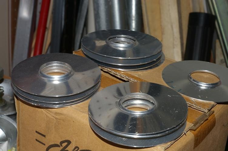
2 I rough cut the aluminum shims out using a bandsaw. I cut out 4" squares and then drilled a 1/4" hole 2" from one edge. Then drill a hole in a board 2" from the edge and clamp the board to the bandsaw. Now the aluminum squares can be spun around a 1/4" pin and cut to rough 4" diameter. Be sure to keep the protective plastic on the aluminum and cut them out with the plastic side down or else the aluminum will get very scratched. Cover the surface of the aluminum sheet with tape if there is no plastic on it. The final size is approximately 3.85" diameter. That dimension is not critical, but minimum variation from one part to the other is important because they want to fit into the forming tool without free play in order to have the formed flange come out the same height all around. I ended up bolting them all together through the 1/4" hole and turning 27 of them down to 3.85" all together. A lathe is not required. They could be placed over a pin in another board, one at a time, and sanded to final diameter. The board can be slid up against stops clamped to a bench with a belt sander clamped to the bench at the correct distance. Only 23 or 24 are needed but I wanted some extras in case I messed some up. I used a 1-1/8" hole saw to cut the center hole. Then deburr. This makes a shallow (about 3/32"-1/8" high) flange, similar to what was in my plane. A 1" hole will make a taller flange, but it might need to have the aluminum annealed with a torch around the


3 inner hole diameter in order to form the taller flange without cracking. I press formed four shims with a 1" hole and two of them cracked. I didn't try annealing, I just went with the larger hole and shallower flange for the rest of them. Disks ready for forming

4 A piece of 1-1/4" EMT tubing a few inches long is inserted into an oak board to make the forming tool. A 1-1/2" hole in the board made with a hole saw allows the EMT to be pushed in flush with the opposite face. The dimensions of 1-1/4" EMT are a little over 1-1/2" OD and a little over 1-3/8" ID. The inner edge of the EMT is quarter-round radiused across the full thickness of the tube to provide the bend radius for the aluminum shims. The other clamping board has a 1-3/8" hole. A short metal spacer is inserted in the 1-3/8" hole to keep the 1-1/4" ball bearing centered. The spacer is made from a short piece of the 1-1/4" EMT tube with a 3/8" wide slit cut out of it so it can be bent to fit in the 1-3/8" hole.


5 Clamp the aluminum shim between the oak blocks. When drilling the holes for the 1/4" bolts in the blocks, begin with them slightly offset toward the center and then carefully file or otherwise enlarge them so that the aluminum shims are centered on the large holes and with no play between the bolts and the aluminum.


6 Install the slit EMT spacer in the 1-3/8" hole and apply wax to the 1-1/4" steel ball and insert into the hole for the first forming operation.


7 Cut a hollowed out depression in the center of a wood block or dowel to use as a pusher. Press the steel ball through the hole in the aluminum using a vise or heavy hammer.


8 Remove the slit EMT spacer and press the waxed 1-5/16" steel ball through. The formed shim will have a slight dished shape that can be flattened by putting a steel plate over top of the hole and squeezing the shim between the EMT and the plate in a vise or with a hammer.

9 Finished shims
Reversing Gear. Shay Reversing Gear
 Shay Nelson Riedel Nelson@NelsonsLocomotive.com Initial: 9/23/03 Last Revised: 06/05/2004 The reversing gear is another one of those pieces I've been putting off. The reason for the postponement was that
Tools: Sharpie, Square, Vise, Hack saw, Ruler, Punch, Hammer, File. 2. Cut the stock Place stock in vise and cut with hack saw
 Purpose: MAKE CATAPULT ARM Step 1 Tools: Sharpie, Square, Vise, Hack saw, Ruler, Punch, Hammer, File Materials: Flat aluminum ½ inch stock (see picture below) Gloves required 1. Pick up the aluminum ½
SLW 6 Channel Letter Brake. User Guide. Operation and Mounting Instructions
 SLW 6 Channel Letter Brake User Guide Operation and Mounting Instructions Scope This document describes the operation and mounting instructions for the SLW 6" Channel Letter Brake. Please read all instructions
Shay Drive Shafts & Universal Fabrication
 Shay Drive Shafts & Universal Fabrication Nelson Riedel Nelson@NelsonsLocomotive.com Initial: 5/22/03 Last Revised: 06/06/2004 The following describes how I machined the universal rings and drive shafts.
C70 Window Roller Repair Taken from: Heres the problem:
 C70 Window Roller Repair Taken from: http://www.volvospeed.com/vs_forum/topic/115086-how-to-c70-window-rollers-permanent-fix/ Heres the problem: This happened to two separate window assemblys on my c70
STANDARD CANOPY WORK REPORT B-1
 STANDARD CANOPY WORK REPORT B-1 No. Check Parts / Tools Qty _ Canopy Lock 1 [ ] 6E2-3 Canopy Hinge Block 1 2 [ ] 6E4-5 Canopy Side Frame 2 2 [ ] 6E2-1 Canopy Lock Assembly 1L + 1R 3 [ ] 6E2-4 Rear Lock
1949 to 1954 Chevrolet Dual Master Cylinder Conversion
 1949 to 1954 Chevrolet Dual Master Cylinder Conversion This document is a one stop shop to getting your brake system updated on your old Chevy. Whether you re going with a disc conversion or just sticking
IIHS Side Impact Outrigger
 IIHS Side Impact Outrigger Assembly Procedure Base Assembly (14.3 lbs) The base assembly consists of a ¼ thick steel plate, a ¼ thick piece of polyethylene, and mounting fixtures for the upper and lower
AR-15 Lower Receiver Assembly Instructions
 AR-15 Lower Receiver Assembly Instructions Tools There are a few tools that make it easier to put together these kits, but none of them are necessary. Minimum requirements include a hammer and punch to
SERVICE BULLETIN
 SERVICE BULLETIN 16-03-28 Date Released: May 6, 2016 (Initial Release) June 2, 2016 (Added Note, pg.11) Date Effective: May 6, 2016 Affected Models: Subject: Required Action: All RV-3, 4, 6/6A, 7/7A, 8/8A,
ASSIGNMENT 4. Textbook Assignment: The point, edge, face, heel, and tang are the five parts of which of the following tools?
 ASSIGNMENT 4 Textbook Assignment: "Files," "Grinders and Sharpening Stones," "Scrapers," "Awls," "Bolt and Cable Cutters," "Glass Cutters," "Knives,' 'Pipe Cutting and Threading Tools," "Tube Cutting and
Ford Pick Up Rear leaf Spring Kit Installation Instructions
 1948-1956 Ford Pick Up Rear leaf Spring Kit Installation Instructions 1-800-984-6259 www.totalcostinvolved.com Parts 48 inch leaf (2) springs (4) U-bolts 3/8-24 x l 1/4bolts (16) & nuts (2) 1/2-20 x 4
FORWARD FUSELAGE SIDES & REAR TOP SKINS
 FORWARD FUSELAGE SIDES & REAR TOP SKINS WORK REPORT Step No. Check Parts / Tools Qty Preparations. 1 [ ] 6F5-3 Upper Front Longerons 2 2 [ ] 6F5-5 Heel Support 1 3 [ ] 6F5-2 Front Floor Skin 1 3 [ ] Firewall
1. Begin by rolling your window up all the way 2. Remove your door and window handles by unscrewing the flat head set screws behind each handle.
 1. Begin by rolling your window up all the way 2. Remove your door and window handles by unscrewing the flat head set screws behind each handle. 3. Remove the 12 screws that attach the steel interior door
CENTER WING SECTION (CWS) WORK REPORT
 WORK REPORT") CENTER WING SECTION (CWS) WORK REPORT No. Check Parts / Description Qty PHASE 1: Preparations 1 [ ] 6V1-3 Rear ribs 2R & 2L 1 [ ] L Angle 6 2 [ ] 6V2-1 Rear Ribs.032 2R & 2L 2 [ ] 6V5-1 Gear Rib Doubler
CENTER WING SECTION (CWS) WORK REPORT No. Check Parts / Description Qty PHASE 1: Preparations 1 [ ] 6V1-3 Rear ribs 2R & 2L 1 [ ] L Angle 6 2 [ ] 6V2-1 Rear Ribs.032 2R & 2L 2 [ ] 6V5-1 Gear Rib Doubler
Contrivance. sample. a modular mechanism machine. design by Derek Hugger. Important:
 sample Important: McMaster Carr, a supplier whose part numbers are referenced throughout this document, can only ship within the United States. Builders outside of the U.S. must find an alternate supplier
advanced metal The pachinko balls rotate freely in their 18k gold flanged cages. The bracelet is 102 x 11mm (4 x 7 16 in.). facetjewelry.
. facetjewelry.") advanced metal The pachinko balls rotate freely in their 18k gold flanged cages. The bracelet is 102 x 11mm (4 x 7 16 in.). FCT-MWON0216_ART26 2006 Kalmbach Publishing Co. This material may not be reproduced
advanced metal The pachinko balls rotate freely in their 18k gold flanged cages. The bracelet is 102 x 11mm (4 x 7 16 in.). FCT-MWON0216_ART26 2006 Kalmbach Publishing Co. This material may not be reproduced
(2) 12mm x 40mm Bolt Plate (long) pictured w/plastic retainer. (6) 12mm x 40mm Bolt Plate (short) Support Bracket Driver/left Front
 12mm x 40mm Bolt Plate (long) pictured w/plastic retainer. (6) 12mm x 40mm Bolt Plate (short) Support Bracket Driver/left Front") PARTS LIST: 1 Driver/left Running Board w-1 Backing 8 12mm Plastic Retainers 1 Passenger/right Running Board w-1 Backing 8 12mm x 32mm x 3mm Flat Washers 2 2 inch tall rubber backing (SX & Limited only)
PARTS LIST: 1 Driver/left Running Board w-1 Backing 8 12mm Plastic Retainers 1 Passenger/right Running Board w-1 Backing 8 12mm x 32mm x 3mm Flat Washers 2 2 inch tall rubber backing (SX & Limited only)
INSTALLATION INSTRUCTIONS SIDE BAR FORD ESCAPE & MAZDA TRIBUTE PART #
 INSTALLATION INSTRUCTIONS SIDE BAR 2008-2010 FORD ESCAPE & MAZDA TRIBUTE PART # 50136 50137 PARTS LIST: 1 Driver/Left Sidebar 2 10-1.50mm x 35mm Bolt Plate 1 Passenger/Right Sidebar 2 10-1.50mm x 30mm
Build a Drill Press Vise
 Youth Explore Trades Skills Introduction This activity plan will develop the student s machining and metalworking skills as they fabricate a multi-piece steel vise. The project will encompass basic lathe
Salter Industries Spiral Stair
 Salter Industries Spiral Stair The Leader in Spiral Staircases Continuous Sleeve Stair Installation Instructions TOOLS NEEDED: 1. Electric drill with hex chuck and Phillips bit 2. Drill bits 1/8", 1/4",
MB-105 BENDER INSTRUCTION SET PRO-TOOLS 7616 INDUSTRIAL LANE TAMPA, FLORIDA PHONE FAX
 MB-105 BENDER INSTRUCTION SET PRO-TOOLS 7616 INDUSTRIAL LANE TAMPA, FLORIDA 33637-6715 813-986-9000 PHONE 813-985-6588 FAX ASSEMBLY INSTRUCTIONS IN THE FOLLOWING INSTRUCTIONS WE WILL EXPLAIN THE ASSEMBLY
SE5a Instrument Board part 2 - rev 1.1
 SE5a Instrument Board part 2 - rev 1.1 Fuel (Petrol) Valve This valve uses two circular name plates, eight brass screws, one black plastic base, copper wire and two black plastic risers. You can pick any
HMP-200 BENDER INSTRUCTION SET
 HMP-200 BENDER INSTRUCTION SET HMP-200 BENDER ASEMBLY INSTRUCTIONS STEP 1 STEP 2 BOLT LEFT SIDE PLATE TO BASE AS SHOWN WITH 1/2 x20 HEX BOLT & FLAT WASHER WELD BASE TO PLATE ON EACH SIDE NOTE: OFFSET HOLE
Hinge Mortising Jig. One of the make it or break it parts of building a. 6 ShopNotes No. 74
 Hinge Mortising Jig A Mortise for a Hinge. Quick, clean, and accurate that s the only way to describe the mortise you get with a trim router and this hinge mortising jig. One of the make it or break it
Post & Rail Crossbuck
 Post & Rail Crossbuck 1. Getting Started 6. Crossbuck Be sure to call underground prior to digging Assemble gates (if necessary) and decide where they will be located Stake out the fence line Space and
INSTALLATION INSTRUCTIONS 3 BULL BAR 99-04, 04 "HERITAGE" F-150/250LD 2WD, 97-04, 04 "HERITAGE" 4WD WD EXPEDITION/ WD EXPEDITION PART
 INSTALLATION INSTRUCTIONS 3 BULL BAR PART #B-F1971;B-F2971 PARTS LIST: 1 Bull Bar 2 12-1.75mm x 130mm x 40mm Hex Bolts 1 Driver/Left Mounting Bracket 4 12-1.75mm x 35mm Hex Bolts 1 Passenger/Right Mounting
HD installation guide
 JANUS INTERNATIONAL 1 866 562 2580 www.janusintl.c o m 1950 1950HD installation guide RIGHT DRIVE END SHOWN LH OPPOSITE LEFT TENSION END SHOWN RH OPPOSITE PUSH-UP OPERATION 1950 1950HD SHOWN A rolling
Note - the nose ribs and are thinner than the main ribs. These nose ribs will use a thinner rib cap than the ribs. This is per design.
 Stabilizer rev 1.2 The SE5a stabilizer is the heartbeat of the tail and is recreated like the full scale version. All tail pieces depend on the stabilizer. It uses the steel fittings, pulleys, inspection
Exploration of a Student Project in a Materials Processing Course
 Paper ID #8093 Exploration of a Student Project in a Materials Processing Course Prof. Somnath Chattopadhyay, Georgia Southern University c American Society for Engineering Education, 2013 EXPLORATION
Assembly & Construction Procedures
 Assembly & Construction Procedures Foreword: This device was designed as an open source open architecture technology. With that in mind the construction of this device was made to be extremely flexible.
Woodline USA Woodline Spacer Fence System
 Woodline USA Woodline Spacer Fence System MADE IN THE USA Includes: (1) ¼ Spacer Fence (1) 3/8 Spacer Fence (1) ½ Spacer Fence (1) Hardware Package (1) 3 Piece Brass bar set (2) Setup Blocks Visit Us Online
RH-412 STEEL DOORS INSTALLATION INSTRUCTIONS
 RH-412 STEEL DOORS INSTALLATION INSTRUCTIONS By following the steps outlined below, the assembly, installation and adjustment of the steel doors, will be a simple process. Let s start with the Driver Side.
Operating Instructions
 Operating Instructions Holding the material against the angle gauge slide it into the forming head. Be sure that the material remains against the gauge until work is finished. NOTE: This machine will handle
HOME WORKSHOP HANDBOOK Rugged BENCH GRINDER. By JOEL B. LONG
 6 HOME WORKSHOP HANDBOOK Rugged BENCH GRINDER W By JOEL B. LONG ITH this bench grinder you can keep your cutting tools sharp and do general offhand grinding, and can, with the aid of various attachments,
INSTALLATION INSTRUCTIONS RH 412 STEEL DOORS
 By following the steps outlined below, the assembly, installation and adjustment of the steel doors, will be a simple process. Let s start with the Driver Side. Note: Having the hood open makes the job
TIRE RACK INSTALLATION INSTRUCTIONS Dodge Sprinter
 Aluminess Products Inc 9402 Wheatlands Ct. #A Santee, CA 92071 619-449-9930 TIRE RACK INSTALLATION INSTRUCTIONS 07-11 Dodge Sprinter Please read before beginning Stainless steel hardware may bind together
LocoGear. Technical Bulletin - 14 November 28, 2003 Copyright 2003 by LocoGear LIVE STEAM CASTINGS. Tech Bulletin - 14
 LIVE STEAM CASTINGS LocoGear Tech Bulletin - 14 John D.L. Johnson 3879 Woods Walk Blvd Lake Worth, FL 33467-2359 jjohnson@locogear.com www.locogear.com Technical Bulletin - 14 November 28, 2003 Copyright
Locker Pedestal Installation Instructions
 Locker Pedestal Installation Instructions LK-PED-INST-0314r1 Parts List Single Pedestal Back to Back Pedestal Horizontal Support Tube TS-169 Post Flange TS-190 Post Cap Fasteners Provided: #8 x ¾ round
1 of 12 5/24/2015 9:43 AM
 1 of 12 5/24/2015 9:43 AM REAR PROPELLER SHAFT ASSEMBLY Components REMOVAL 1. REMOVE PROPELLER WITH CENTER BEARING SHAFT ASSEMBLY 2 of 12 5/24/2015 9:43 AM a. Place match marks on the propeller shaft flange
Before returning this product to the store of purchase
 Before returning this product to the store of purchase Contact Dee Zee if you experience the following problems: Missing Parts Installation Problems/Questions Warranty Questions 1.800.779.2102 Hours of
Slide the stock rubber tank mount caps onto the ends of the CS-1 tank mount:
 RYCA CS-1 BODY PARTS INSTALLATION GUIDE [The CS-1 installation guides should be used as supplements to the videos found on our Youtube Channel. There is no strict order to the build process, but it is
Clocking a TD-04 Turbo Compressor Housing. Appendix A : AWIC Silicone and Tubing Fitting
 Clocking a TD-04 Turbo Compressor Housing Appendix A : AWIC Silicone and Tubing Fitting Revision A: 7-13-2015 Tools: Metric Sockets (10, 12, 14, 17mm) 5mm Hex Key Large Internal Snap Ring Pliers 3/8 Socket
Project Identity. Assistive Robotic Arm Week 9 March April 4, 2007 Megan Madariaga
 Project Identity Assistive Robotic Arm Week 9 March 28 2007- April 4, 2007 Megan Madariaga Work Completed: On Friday March 30 th we filled out the return sheet for our large base motor then traveled to
METAL BENDER OPERATING & MAINTENANCE INSTRUCTIONS Model Nos: CCB1 & CCB2 Part Nos: & CCB2 CCB1
 METAL BENDER Model Nos: CCB1 & CCB2 Part Nos: 7630073 & 7630074 CCB2 CCB1 OPERATING & MAINTENANCE INSTRUCTIONS 1206 1 The Compact Bender allows you to economically make a variety of bends in flat, square,
Skybolt V2 Construction Manual
 Skybolt V2 Construction Manual Property of www.ppgplans.com Do not duplicate or make public. Warnings & Disclaimers. This product shows how to build a basic frame only for Powered Paragliding. It is the
Obtained from Omarshauntedtrail.com
 DaveintheGrave's Halloween Props Animated Crawling Skeleton Build a life-size skeleton torso that realistically crawls across the lawn one arm at a time. 1. Motor Base and Linkage Assembly BASE - I used
C-180 Builder s Manual
 C-180 Builder s Manual. May 20, 2002 Last revised July 11, 2002 Copyright! 2002 Douglas Binder, Mountain Models www.mountainmodels.com sales@mountainmodels.com (719) 630-3186 1 Required Equipment! Xacto
AndyMark DART 12.
 AndyMark DART 12 Part Number Description QTY These Parts Are Pre-Assembled by AndyMark am-0031 Bearing, 3/16"ID (R3) 1 am-0209 Bearing, 3/8"ID 1614ZZ 2 am-1028 Screw, #10-32x3/8 Pan Head Philips 8 am-1121
INSTALLATION INSTRUCTIONS PART#:17A096400MSS\17A096400MA MODULAR GRILL GUARD FOR TOYOTA TACOMA 05-09
 INSTALLATION INSTRUCTIONS PART#:17A096400MSS\17A096400MA MODULAR GRILL GUARD FOR TOYOTA TACOMA 05-09 1 guard, center section 1 brush guard, left side 1 brush guard, right side 1 wire guard insert, left
SAW ARBORS B MADE IN THE * * * * * * * USA USA * * * * * * * A B C D E SSA-500
 SAW ARBORS B SIDE MILLING SAW ARBORS With Quad Key Drive Assist FEATURES: The only SEMI-FLUSH keyed (removable) arbor for cutter with or without a drive key.0004 TIR Made from domestic 4340 aircraft alloy
Wind Pump Construction
 What Will You Need? Page 1 The following components can be found in your kit, and are needed to build one wind pump: 50 Tooth Gear* 40 Tooth Gear* 20 Tooth Gear* 10 Tooth Gear* Wheel Hub 300mm (~12in)
STOL CH 801 SECTION 2: Nose Rib 8R1-7
 SECTION 2: Nose Rib 8R1-7 Position the lower nose rib on the front of the spar at the predrilled holes just above rear rib #3 (615mm from the bottom of the spar) Check lateral alignment (rib is centered
LU6X-130 Instructions and Parts List (including LU6X Basic) Operating Instructions
 Operating Instructions") LORTONE LU6X-130 Item # 061-092 LU6X Basic Item # 061-090 LU6X-130 Instructions and Parts List (including LU6X Basic) Operating Instructions Introduction The LU6X is one the most versatile pieces of equipment
LORTONE LU6X-130 Item # 061-092 LU6X Basic Item # 061-090 LU6X-130 Instructions and Parts List (including LU6X Basic) Operating Instructions Introduction The LU6X is one the most versatile pieces of equipment
`48-`56 Ford Pickup Rear leaf Spring Kit Installation Instructions Tech Line:
 `48-`56 Ford Pickup Rear leaf Spring Kit Installation Instructions Tech Line: 1-855-693-1259 www.totalcostinvolved.com CHECK ALL PARTS INCLUDED IN THIS KIT TO THE PARTS LIST BEFORE INSTALLING THE KIT.
Warnings. Description. Prior to Installation Tools Needed
 Warnings Failure to act in accordance with the following may result in death or personal injury. The JT Strong Arm Stabilizer System is intended to eliminate chassis movement in travel trailers and fifth
In-Tube Motorized SCREEN-PRO. All Season Roll-Up Doors IN-JAMB MOUNTING METHOD INSTALLATION INSTRUCTIONS READ THIS FIRST
 In-Tube Motorized SCREEN-PRO All Season Roll-Up Doors IN-JAMB MOUNTING METHOD INSTALLATION INSTRUCTIONS READ THIS FIRST Carefully examine the crate(s) for damage before opening. If the carton is damaged,
USSC LLC 4 ONE LLC FIELD MODIFICATION INSTRUCTIONS
 1 OF 17 A 1. PURPOSE: Instructions for in field replacement of 9004 mechanical suspension top pan 2. SCOPE: 9004 mechanical suspension with legacy two point LX back frame and current LX back frame 3. PROCEDURE:
Installation Instructions
 DODGE 16K Industry Standard Rail Custom Mounting Kit #2728 Gross Trailer Weight (Maximum)...16,000 lbs. Vertical Load Weight (Max. Pin Weight)...4,000 lbs. SYSTEM TOW CAPACITY Please note, in order to
MantelMount. TM1A Installation Instructions IMPORTANT SAFETY INSTRUCTIONS - SAVE THESE INSTRUCTIONS
 MantelMount TMA Installation Instructions IMPORTANT SAFETY INSTRUCTIONS - SAVE THESE INSTRUCTIONS TM Thank you for choosing the MantelMount television wall mount. Please read this entire manual before
The terms folding or braking are used when it is a question of bending a sheet of metal to a given angle and along a straight line.
 Extracted from the plans by Michel Columban for the Cri-Cri/Cricket, found on the web. Used WITHOUT permission. My notes, including English dimension, are THUS - RRY. 7. Metal Folding 7.1 Definition The
Greene & Greene. Mailbox. by Seth Keller. Signature details create an elegant box. 2 AmericanWoodworker.com
 Greene & Greene Mailbox by Seth Keller Signature details create an elegant box. 2 AmericanWoodworker.com We needed a new mailbox, but I couldn t find an off-the-shelf version that I liked. So I decided
16. Wing Final Assembly and Installation
 Section Objective: Installation and rigging of ailerons. Pitot tube install, and any other wing related items. Required Parts: Left aileron push rod ALA-0072, Right aileron push rod ALA-0073, Push tube
(W) INSTALLATION INSTRUCTIONS 3" ROUND & 4" OVAL SIDEBAR (90-DEG BENT END) DODGE RAM 1500 QUAD CAB PART #DZ /DZ /DZ /DZ
 INSTALLATION INSTRUCTIONS 3 ROUND & 4 OVAL SIDEBAR (90-DEG BENT END) DODGE RAM 1500 QUAD CAB PART #DZ /DZ /DZ /DZ") (W) INSTALLATION INSTRUCTIONS 3" ROUND & 4" OVAL SIDEBAR (90-DEG BENT END) PART #DZ 372231/DZ 372233/DZ 372237/DZ 372239 PARTS LIST: 3" ROUND & 4" OVAL SIDEBAR (90-DEG BENT END) Qty Description Qty Description
(W) INSTALLATION INSTRUCTIONS 3" ROUND & 4" OVAL SIDEBAR (90-DEG BENT END) PART #DZ 372231/DZ 372233/DZ 372237/DZ 372239 PARTS LIST: 3" ROUND & 4" OVAL SIDEBAR (90-DEG BENT END) Qty Description Qty Description
This go-round puts kids in orbit
 This go-round puts kids in orbit By DAVID A. GATTIS You DON'T NEED NASA to put your kids in orbit. They'll really get a blast out of this attachment that adds whiz-around variety to the backand-forth motion
Sheet Metal Tools. by:prem Mahendranathan
 Sheet Metal Tools by: SHEET METAL TOOL KIT SHEET METAL TOOLS Rivet Gun 3/32, 1/8, 5/32, 3/16",Cupped Set Mini Bucking Bar Footed Heel-Toe Bucking Bar Air Tool Oil Mechanics Tool Bag High-Speed Air Drill
installation guide
 JANUS INTERNATIONAL 1 866 562 2580 w w w. j a n u s i n t l. c o m 2000 2500 3000 installation guide RIGHT DRIVE END SHOWN LH OPPOSITE LEFT TENSION END SHOWN RH OPPOSITE PUSH-UP OPERATION 2000 2500 3000
135 ROLLTOP DESK 515
 135 ROLLTOP DESK 515 For the person who hates to clear off a desk, who wants to leave everything where it is overnight yet still have the clutter hidden, a rolltop desk is a godsend. The tambour hides
Low/High Tunnel Greenhouse Plans
 Low/High Tunnel Greenhouse Plans Tools Needed (See the complete list of Greenhouse Tools) Hacksaw or Reciprocating Saw Socket Wrench, Adjustable Wrench or Nut Drivers Electric Drill with Drill Bits Sledge
w w w. h d o n l i n e s h o p. d e TIMKEN BEARING CONVERSION TOOL GENERAL INSTALLATION -J04672 REV Kit Number Models
 -J067 REV. 008-07- GENERAL Kit Number 8-08 Models TIMKEN BEARING CONVERSION TOOL For model fitment information, see the P&A Retail Catalog or the Parts and Accessories section of www.harley-davidson.com
INSTALLATION INSTRUCTIONS 6 OVAL BENT END SIDEBARS DODGE RAM 1500, CREW CAB PART#: /241533B
 PARTS LIST: 1 Driver/Left Sidebar 24 8mm x 24mm x 2mm Flat Washers 1 Passenger/Right Sidebar 12 8mm Lock Washers 3 Driver/left, Passenger Center and Rear 6 8mm Hex Nuts 3 INSTALLATION INSTRUCTIONS 6 OVAL
THE ROGUE TM FUNSLIDE TM
 THE ROGUE TM FUNSLIDE TM ASSEMBLY AND INSTALLATION INSTRUCTIONS * * C A U T I O N * * S.R. SMITH ROGUE TM FUNSLIDES TM ARE MANUFACTURED FOR INSTALLATION AND USE ON RESIDENTIAL INGROUND POOLS ONLY. ROGUE
Al & Gary's Illusionist Heart
 Al & Gary's Illusionist Heart Plans and Instructions by: Albert Herwig and Gary A. Emerich Al & Gary's Illusionist Heart As Al Would Say: It's a pendant Now it's a heart Our pictures are in there My children'
QUARTER-SCALE MERLIN PROJECT
 QUARTER-SCALE MERLIN PROJECT Crankcase Group 12/24/02 page 1 This is a draft of instructions for machining the crankcase group. They are offered as a suggested method only, with the realization that experienced
CUT OUT FLARES INSTALLATION INSTRUCTIONS FOR 20017, 20018, F100-F150 F250-F350 P.U. & BRONCO CUT OUTS
 20017 04/22/03 REV-A CUT OUT FLARES INSTALLATION INSTRUCTIONS FOR 20017, 20018, F100-F150 F250-F350 P.U. & BRONCO CUT OUTS Tools Required for Installation: (A) 3/16 Drill Bit (B) Pop-Rivet Gun (C) Air
Jump rings may be made most easily by using a small hand drill with various sizes of mandrel.
 Jump Ring Notes Copyright Charles Lewton-Brain 1997 Jump rings may be made most easily by using a small hand drill with various sizes of mandrel. Take a broken burr, old needle file handles or a piece
After the canopy hinge is square with the firewall and the nut plates are installed you can set up the hinge mounts. Start by clamping a 1/16 tongue
 Written by: Sean Cole September 19, 2008 When fitting the stiffener use 3/32 clecos to hold it in place, it makes a smaller hole and is easier to work with. Only use the amount needed to hold the stiffener
10 x 10 Flat Top Two Tone Pergola
 0 x 0 Flat Top Two Tone Pergola Models: Bordeaux ASSEMBLY GUIDE OPTIONAL ACCESSORIES Arch Kit System ( Arches) Privacy Fence Panel System ( Panels & Middle Post) Bolt Down Bracket Kit ( for Pergola) Ver.0-00
ELIZABETH 30 SPINNING WHEEL
 INSTRUCTIONS ELIZABETH 30 SPINNING WHEEL Single and Double Treadle Ashford Handicrafts Ltd. Factory and Showroom: 415 West Street, PO Box 474, Ashburton, New Zealand Telephone 64 3 308 9087 Facsimile 64
Installation Manual Using Existing Handrail Version 4.0 Oct 2017
 Installation Manual Using Existing Handrail Version 4.0 Oct 2017 ORDER OF ASSEMBLY TOOLS YOU WILL NEED - Fine Saw - Sander - Wood Filler - Allen keys - Screw Driver - Drill - Suitable Screws PROTECTING
REAR FUSELAGE ASSEMBLY
 SECTION 2 Rear Fuselage Bottom Assembly Ref Dwg 8FR-2 SECTION 2 - Page 1 of 17 FUSELAGE BOTTOM SKIN 8F2-3A Note: The edges of skin 8F2-3A are not a straight line. Check: edge distance from the center of
Table Saw Disc Sander
 instructables Table Saw Disc Sander by tomatoskins A disc sander is a must for any shop! They make quick work of shaping and smoothing stock. Getting the most out of your shop tools can often take you
Regulator installation guide Air Arms S4xx/S5xx
 Welcome to Huma-Air. We design and manufacture brand- and model specific precision regulators for PCP air rifles. By using only the highest quality materials such as aircraft grade aluminum, aluminumbronze,
Premium Single Dutch Doors Assembly & Installation Instructions
 Premium Single Dutch Doors Assembly & Installation Instructions Premium Single Dutch Door Instructions General Notes; -Read the entire instructions before you begin. -Wear appropriate safety gear when
!! " # $ % & '! ( ) * +, -
 * +, -") !! " # $ % & '! ( ) * +, - North Pegasus This carton contains: (1) Instruction package. Response Curves North Creek Cabinet Handbook North Creek Wiring Guide (2) 6 oz. Rolls of Dacron stuffing. (1) Tube
!! " # $ % & '! ( ) * +, - North Pegasus This carton contains: (1) Instruction package. Response Curves North Creek Cabinet Handbook North Creek Wiring Guide (2) 6 oz. Rolls of Dacron stuffing. (1) Tube
IBEX 1132 REAR AXLE UCA TRUSS GOAT BUILT IBEX REAR AXLE UPPER CONTROL ARM BRACKET/TRUSS
 GOAT BUILT IBEX REAR AXLE UPPER CONTROL ARM BRACKET/TRUSS Thank you for purchasing Ibex chassis kit components, before starting your build, we recommend that you read through these instructions to familiarize
Drilling Your Wings to Your Fuselage
 Drilling Your Wings to Your Fuselage The purpose of this write up is to give some further guidance on how to get the best results drilling your wing spar attach holes to the upper fuselage attach fittings.
Make your own zero clearance throat plate.
 Make your own zero clearance throat plate. A picture tutorial By Wayne Breshears One of the more important table saw accessories you can have is a zero clearance insert or throat plate. The close tolerance
Jimmy s 2 nd demonstration was what he called an African Drum style box made from Iroko with a cocobolo insert in the lid with inlaid sterling silver.
 Jimmy s 2 nd demonstration was what he called an African Drum style box made from Iroko with a cocobolo insert in the lid with inlaid sterling silver. He started by roughing out the block with a roughing
TRUE TECHNICAL SERVICE MANUAL - ALL MODELS. DOORS/DRAWERS/LIDS
 DOORS/DRAWERS/LIDS 55 56 NOTES DOORS/DRAWERS/LIDS Springs 97 TORSION SPRING REPLACEMENT GDM RADIUS FRONT - SWING DOOR INSTALLATION INSTRUCTIONS Tools Required (2) - 1 8" drift Punch (forged) Needle-Nose
The saw is not a decoration piece but sees regular use at the school. The cross pieces at either end are made from oak, the long stretchers are made
 Roy s Saw When you walk in the front door of Roy Underhill s Woodright s School and look to your left in the window hanging above Roy s stuffed chicken is a large frame saw. Now the chicken is an interesting
J D SQUARED INC. NOTCH MASTER Tube and Pipe Notcher Operating Instructions
 Copyright (c) 2006 J D SQUARED INC. www.jd2.com NOTCH MASTER Tube and Pipe Notcher Operating Instructions Angled Notches PATENT PENDING Straight Notches Offset Notches Tube Clamp Slider Tube Clamp Exploded
Learn how to make decorative rivets while working with this uncommon alloy. by Addie Kidd
 PROJECT INTERMEDIATE METAL Shibuichi Cuff: Learn how to make decorative rivets while working with this uncommon alloy. by Addie Kidd To take full advantage of shibuichi, you ve got to use patinas. One
Aluminum and Steel Machined Flaperon Handle for Belite Aircraft ASSEMBLY INSTRUCTIONS. Last Revised January 7, 2016
 Aluminum and Steel Machined Flaperon Handle for Belite Aircraft ASSEMBLY INSTRUCTIONS Last Revised January 7, 2016 Read and understand all instructions completely before beginning your Flaperon Handle
BEAST THE. Tube and Pipe Notcher Operating Instructions. Notches In Bends Straight Notches. Angled Notches. Offset Notches
 Copyright (c) 2007 J D SQUARED INC. www.jd2.com THE BEAST Tube and Pipe Notcher Operating Instructions Notches In Bends Straight Notches Angled Notches PATENT PENDING Offset Notches Assembly After unpacking
Chain Drive Vise. Installation Instructions. (revised 05/04/2016)
") Chain Drive Vise Installation Instructions (revised 05/04/2016) Lie-Nielsen Chain Drive Vise Instructions Table of Contents page About Your Chain Drive Vise 3 Parts List 4 Exploded Parts Diagram 5 step
Chain Drive Vise Installation Instructions (revised 05/04/2016) Lie-Nielsen Chain Drive Vise Instructions Table of Contents page About Your Chain Drive Vise 3 Parts List 4 Exploded Parts Diagram 5 step
AMETAL SHAPER is indispensable for certain METAL SHAPER FOR YOUR SHOP. By S. S. Miner
 METAL SHAPER FOR YOUR SHOP By S. S. Miner AMETAL SHAPER is indispensable for certain machining operations where flat surfaces must be produced within very close limits, such as machining flats on castings,
136 PLYWOOD DESK 522
 136 PLYWOOD DESK 522 Simple in design and inexpensive, this plywood desk is made from a single 4- x 8-foot panel. Plywood is available with many hardwood veneers; it can also be covered with plastic laminate,
Bulk Storage Rack Assembly Instructions
 Bulk Storage Rack Assembly Instructions Upright Frame Assembly Determine which end of the post goes up. The keystone slots on the front face of the post are wider at the top than at the bottom (see diagram
Bumper Sign INSTALLATION INSTRUCTIONS
 Bumper Sign INSTALLATION INSTRUCTIONS BUMPERSIGN TOOL CHECKLIST SDS MAX Rotary Hammer Drill Marker/Pencil SDS MAX 1 Carbide Drill Bit Tape Measure Torque Wrench with ½ Drive Power Source Vacuum ½ Drive