Haukaas Bale Rack Kit
|
|
|
- Sherman Grant
- 6 years ago
- Views:
Transcription

 355-2718 www.haukaas.")
1 Page 1 Haukaas Bale Rack Kit For hauling large round bales "Pipe Style". C D Pocket Reinforcement Plates 10" 11" A: Pocket Side Plate B: Pocket Top Plate C: Side Stake D: End Stake E: Floor Plate B A F: Under Floor Plate G: T-Connector Plate H: Flag Plate I: Sign Plate J: End Cap E F I J Kit requires 2-7/8" OD pipe and some welding. Stake size 3"x 1-1/2" - sign and flag holders. G H Haukaas Mfg. Ltd. Mortlach, SK. Canada (306) These instructions can be found on line at

2 Side Rails SR - 1 Bulkheads BP - 1 BP - 2 BP - 3 BP - 4 Page 2
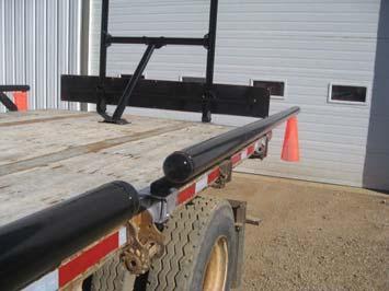
3 Haukaas Bale Rack Instructions We would like to thank you for purchasing the Haukaas Bale Rack Kit. Due to the many different trailers available, we feel that the best way to provide well designed Bale Racks to the market place is to provide the components that required designing and could be mass produced leaving the 2-7/8 OD pipe and the final welding to the end user. The person(s) welding and installing the racks for the end user will be responsible for the completed rack system to ensure that the racks are properly welded and installed. We recommend the 2-7/8 OD pipe has a wall thickness of.203 or heavier. (Schedule 40) All welding is to be done in accordance with CSA Standard W59-03 (2008) Welded Steel Construction (Metal Arc Welding) or American Standard AWS D1.1:2004 Structural Welding Code Steel. 1/4 fillet welds or greater should be used throughout. Installation Time We expect that it will take approximately 8 hours for a welder and welder s helper to weld and install a complete system (Side Rails and Bulkheads). Cutting time for the pipe and painting is not included in this time. Side Rails In designing the racks we planned for there to be two side stakes per side rail. We want the side rails to be easily removed by two people. We feel that more than two stakes per rail would cause for more binding. Due to the varying of the trailers these kits are used on it will be the end users responsibility to determine the number of stakes and their locations on the trailer and the pipe lengths that will be used. (See SR-1 page 2). Stake Pockets In this kit we have provided Pocket Top Plates and Pocket Side Plates. We strongly recommend that they be welded to the trailer to provide re-enforcement to the trailer s stake pockets. We believe that many of the trailers receiving this kit will be older and these plates will better ensure a safer bale hauling trailer. Pay close attention to the welding instruction given regarding the welding of the plates to the trailer. Improper welding on the trailer can compromise the integrity of the trailer itself. Rail End Caps The Rail End Caps welded to the rails serve 3 purposes. There is a safety issue for those walking by the trailer and it will reduce the likelihood of snagging the bales and damaging the net wrap. The Rail End Caps also make the whole rack look better! They can be welded to the rails before or after the rails are welded to the stakes. Please Read and Understand these Entire Instructions Before Starting!! Page 3
4 Understanding These Instructions The information given in these instructions is laid out in step by step order. Page 1 shows the overall cad picture of the bale rack system, the names of the components and their general locations. Page 2 shows the general instructions for the side rails, bulkheads and under floor plates. Page 3 and on are the step by step instructions written and with pictures. If you have any questions please call us at (306) Before You Begin You will have to determine the locations for the stake pockets on the trailer both for the side stakes and the end stakes that make up the bulkhead. We used a 53 highboy trailer to make these instructions. We placed the side stakes 72 (6ft) apart and cut the 2-7/8 OD pipe 108 (9 ) for eight of the ten rails. We cut the pipe 120 (10ft) long to get the coverage we wanted for the front two rails. It will be up to the end user to decide what works best for your trailer. The number of side stakes sent with this kit is only a suggestion for your trailer. It will be up to you to decide the location on your trailer as to where you place them. The number of side and end stakes used and their spacing/locations will be the full responsibility of the end user. For the bulkhead end stakes we used the center 2 stake pockets at the front of the trailer. At the rear of the trailer we used the 2 stake pockets that were on each side of the center pocket. You will have to determine the appropriate locations for the end stakes and the number required for the bulkheads for your trailer. On the trailer (53 highboy) that these instructions were made from the Lower Rails were cut 84 long, the Upright Pipes were cut at 80 and the Top Rails at 72. The length of the Angle Pipe and Center Pipe will be determined by your trailer. (See BP-1 page 2). For the bulkhead floor plates we feel that the best location is right over a steel crossbeam and clamp using the Under Floor Plates. The Under Floor Plates can be used two different ways on your trailer. (See BP-4 page 2). The fasteners for the Floor Plates are not included in this kit. Step 1 Lay out the Pocket Top Plates for the side rails and end stake/bulkheads in the locations that you have chosen for them. Step 2, 3 & 4 Using a marker, mark out the areas where the stake pocket re-enforcement plates will need to be welded. Step 5 Remove all paint or rust in the marked areas to prepare for welding. Step 6 With the Pocket Top Plate properly aligned directly over the stake pocket tack weld. Page 4
5 Step 7 Use a Side Stake to check the alignment. Step 8 Position and tack weld the Pocket Side Plate in the proper location. (We left a 1/16 gap between the Pocket Top Plate and Side Plate to make for a better, easier weld). Step 9 Weld the Pocket Side Plate as shown. Step 10 Weld the Pocket Top Plate as shown (there are grooves provided in the Pocket Top Plate to serve as weld guides). It is VERY IMPORTANT that you DO NOT WELD to the sides of the Pocket Top Plates. Welding in these locations may weaken your trailer! Step 11 & 12 Insert and align the Side Stakes. Proper alignment of the Side Stake will ensure straighter rails from the front to the back of the trailer. Centering of the Side Stakes (side to side) in the stake pocket is a good idea. It will make getting the side rails off and on the trailer easier. Step 13 Center the Rail Pipes on the Side Stakes. You can decide whether you weld the End Caps on the Rail Pipes before or after welding the Side Rails to the Side Stakes. Side Rails we suggest welding them before. (See SR-1 page 2) [Note: See Step 19] Step 14 &15 We tacked welded the Side Stakes to the Rail on the bottom and then fully welded along the top of the Side Stake and then fully welded the bottom as shown. Step 16 Once all the Side Rails are welded to the Side Stakes, weld the Flag Holder Plates to the bottom of the rail at each corner of the trailer as shown. (See Step 53-55) Step 17 & 18 We suggest that you number stamp each Side Rail to identify its location. This may greatly reduce any frustrations when installing the Side Rails in the future. Step 19 We suggest that you begin with the front bulkhead. Insert the End Stakes in the predetermined stake pockets on the front of the trailer and slide the Lower Rail into place and center. (On the Lower Rail you may want to weld the End Caps on afterwards). Step 20 Weld the Lower Rail to End Stakes as shown. They need to be welded well enough to be removed from the stake pockets without coming loose. Page 5
6 Step 21 If the Stakes are difficult to remove grinding the edges as shown may help when reinstalling. Step 22 Remove from the trailer and lay the subassembly out on the floor as shown. Step 23 & 24 Measure the inside dimension of the top holes in the End Stakes and cut the Center Pipe to that size as shown. Step 25 Welding the Top Rail: Set out the enclosed T-Plates in line with the End Stake top holes as shown. Step 26, 27 & 28 Welding the Top Rail: Center the Top Rail with the T-Plates and weld as shown. Step 29 Install the bulkhead Upright Pipes (verticals) as shown with top rails. Step 30 Square the Upright Pipes with the Lower Rail as shown. Step 31, 32, 33 & 34 Weld all the components together top side and bottom side as shown. Step 35 Rear Bulkhead: Weld the rear bulkhead together the same as the front. The difference between the front and rear bulkhead are the Sign Holder Plates on the rear bulkhead. Do not forget to install the center Sign Holder Plates when sliding the Lower Rail into place. (See BP-1 & BP-2 page 2) Square the Sign Holder Plates as shown. We used a short length of flat bar running across to square up the holder plates. Step 36 Square Upright Pipes to the Lower Rail as shown. Step 37 Weld the Sign Holder Plates to the Lower Rail as shown. Page 6
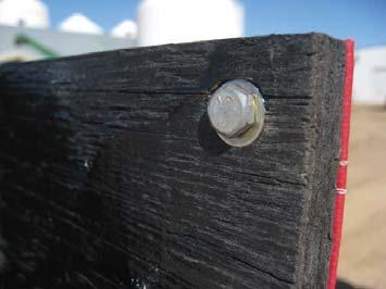
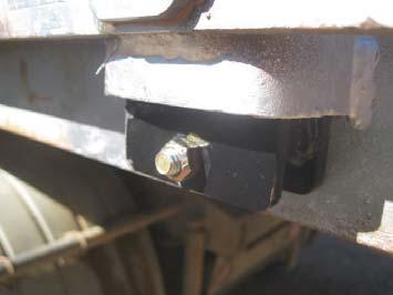
7 Step 38 Locate the Floor Plates and drill holes for fasteners. The Floor Plate is designed to receive the 2-7/8 OD pipe at 45 degrees. When possible locate the Floor Plate directly over a metal crossbeam and clamp it using the enclosed Under Floor Plates. On the trailer (53 highboy) we used lag bolts to secure the front bulkhead s Floor Plate as it was directly over the King Pin plate. If you do the same make sure that you use long 1/2 diameter lag bolts and that they are securely attached to the front bulkhead of the trailer. It is the installer s responsibility to make sure that racking system is secure and safe! Step 39 This picture is of the rear bulkhead and how we fastened the bulkhead to the trailer floor using the Under Floor Plates. We clamped directly to the trailers metal crossbeam. The Floor Plates are designed to use four 1/2 bolts (not included). Step 40 Locating the bulkhead s Center Pipe: Using the diagram BP-1 on page 2 determines the height at which the T-plate should be located. X = the distance from the back of the Floor Plate to the inside edge of the stake pocket. Perhaps the easiest place to measure is from the top of the End Stake. From the top of the End Stake to the bottom of the T-plate is X minus 11. (For example if X on your trailer = 40 then you would measure up 29 [40-11=29] and make a mark to locate the T-plate). Do this (make a mark) on both Upright Pipes. Step 41 Tack weld one T-plate to one of the Upright Pipes in the proper location as shown. Step 42 & 43 Slide the Center Pipe into the T-plate welded to the Upright Pipe. Slide the T-plate for the opposite Upright Pipe (not shown) onto the Center Pipe and swing into place. Locate the T-plate to the proper place (the mark that was made) on the Upright Pipe and weld the subassembly securely. Step 44 The next step is to square the bulkhead (rack) with the deck of the trailer itself. The bulkhead looks far better if it is straight up and down! Step 45, 46, 47 & 48 Measure to determine the length of the Angle Pipe. (See BP-1 page 2) We suggest that the measured length have 3/8 sticking through the T-plate on the Center Pipe. The Angle Pipe will need to have the bottom end cut at a 45 degree angle to fit properly. Step 49 On the trailer (53 highboy) that these instruction were made from the Floor Plate was located a little off center to properly fit the floor boards on the trailer. To compensate so that the Angle Pipe ran straight the T-plate on the Center Pipe was moved a little to the right of center before welding. Page 7
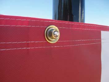
8 Step 50 Weld Angle Pipe to Floor Plate all around and secure. (Weld the connection while fastened to the trailer.) Step 51& 52 We suggest attaching a piece of 5/8 plywood (3/4 if using only 2 Sign Holder Plates) 13 wide and 96 long to hold the D sign. (Plywood not included in this kit.) Included in this kit are 3/8 x 1-1/4 carriage bolts and regular 3/8 nuts to fasten the plywood to the Sign Holder Plates. (See BP-1 page 2) Step Attach the corner flags to the Flag Holder Plates at each of the four corners of the trailer using enclosed 3/8 x 1-1/4 hex bolts and Stover nuts (locknuts). Step Install D-Sign onto the plywood using enclosed 3/8 x 1-1/4 carriage bolts, regular nuts and flat washer Step 60 Install the enclosed 3/8 x 3/4 Hex bolts with the 3/8 Stover nuts into the Side Stakes to ensure that the Side Rails do not come out of the stake pockets accidently. Disclaimer: It is the responsibility of the owner of the trailer to ensure that these instructions are followed and that the bale rack system is properly fabricated and installed. The end user is liable for any damages or harm that may result from the use of these bale racks. We recommend the 2-7/8 OD pipe has a wall thickness of.203 or heavier. (Schedule 40) All welding is to be done in accordance with CSA Standard W59-03 (2008) Welded Steel Construction (Metal Arc Welding) or American Standard AWS D1.1:2004 Structural Welding Code Steel. 1/4 fillet welds or greater should be used throughout. Page 8


9 Mark out the areas that need to be ground before welding. Lay pocket top plates out in their proper locations on the trailer. Mark out the areas that need to be ground before welding. Step - 1 Step - 2 Step - 3 Mark out the areas that need to be ground before welding. Grind clean before welding. Align plate over pocket and tack weld. Step - 4 Step - 5 Step - 6 Check alignment with side stake. Position side plate and tack weld. Weld three sides as shown. Step - 7 Step - 8 Step - 9 Weld as shown. Do Not Weld Here!! Set side stakes in pockets. Make sure stakes fit flush to the trailer here. Step - 10 Step - 11 Step - 12 Center rail pipes on stakes. Weld top as shown. Weld bottom as shown. Step - 13 Step - 14 Page 9 Step - 15


10 Weld flag holder plates on the bottom outside corners. Number stamp stakes and pockets to identify location. Side Stake Complete Step - 16 Step - 17 Step - 18 Bulkheads Insert end stakes and center lower rail. Weld lower rail to end stakes. If stakes are tight in pockets grind edges. Step - 19 Step - 20 Step - 21 Layout on flat floor. Measure inside measurement. Cut center pipe to size. Step - 22 Step - 23 Step - 24 Set out T-plates for top rail. Center top rail with T-plates. Weld T-plates to top rail. Step - 25 Step - 26 Step - 27 Weld top side as shown. Install uprights and top rail. Square uprights with lower rail. Step - 28 Step - 29 Page 10 Step - 30


11 Weld as shown both top and bottom. Weld as shown both top and bottom. Weld as shown both top and bottom. Step - 31 Step - 32 Step - 33 Square sign holder plates. Flat bar Squaring upright with lower rail. Weld as shown both top and bottom. Step - 34 Step - 35 Step - 36 Weld sign plate as shown. Locate bulkhead floor plate. Best location for under floor plates. Step - 37 Step - 38 Step - 39 Measure to locate T- plate for center pipe. Tack weld one T-plate first. Slide center pipe in T-plate. Step - 40 Step - 41 Step - 42 Measure to find measurement. Weld T-plate in proper location. Square bulkhead with floor. Step - 43 Step - 44 Page 11 Step - 45


12 Measure to find measurement. Measure to find measurement. Have angle pipe stick through. Step - 46 Step - 47 Step - 48 Weld when aligned. Weld all around as shown. Attach plywood as shown. Step - 49 Step - 50 Step - 51 Attach plywood as shown. Attach flags as shown. Attach flags as shown. Step - 52 Step - 53 Step - 54 Attach flags as shown. Attach sign as shown. Attach sign as shown. Step - 55 Step - 56 Step - 57 Attach sign as shown. Attach sign as shown. Insert fasteners into Side Stakes. Step - 58 Step - 59 Page 12 Step - 60
Classic Roll Tarp. Installation Instructions. Attention Dealers: Please give this owners manual to the customer when the product is delivered.
 Serving the Truck & Trailer Industry Since 1944 Classic Roll Tarp Attention Dealers: Please give this owners manual to the customer when the product is delivered. Call 800-535-9545 www.aeroindustries.com
ASSEMBLY INSTRUCTIONS FOR MAR-K BEDSIDES AND GM FLUSH TAILGATE WITH HANDLE
 ASSEMBLY INSTRUCTIONS FOR MAR-K BEDSIDES AND 41-53 GM FLUSH TAILGATE WITH HANDLE Build the box assembly according to the MAR-K assembly instructions. When installing the tailgate and latching mechanisms
Ford Pick Up Rear leaf Spring Kit Installation Instructions
 1948-1956 Ford Pick Up Rear leaf Spring Kit Installation Instructions 1-800-984-6259 www.totalcostinvolved.com Parts 48 inch leaf (2) springs (4) U-bolts 3/8-24 x l 1/4bolts (16) & nuts (2) 1/2-20 x 4
The Festival Assembly Instructions
 The Festival Assembly Instructions Toll Free: 866.768.8465 Hours: 9-5 Monday-Friday EST www.homeplacestructures.com Package ships as shown CONTACT INFORMATION: HomePlace Structures 301 Commerce Drive New
Classic Roll Tarp. Installation Instructions. Attention Dealers: Please give this owners manual to the customer when the product is delivered.
 Serving the Truck & Trailer Industry Since 1944 Classic Roll Tarp Attention Dealers: Please give this owners manual to the customer when the product is delivered. Call 800-535-9545 www.aeroindustries.com
Kwik-Lock. Installation Instructions. Attention Dealers: Please give this owners manual to the customer when the product is delivered.
 Serving the Truck & Trailer Industry Since 1944 Installation Instructions Attention Dealers: Please give this owners manual to the customer when the product is delivered. Call 800-535-9545 www.aeroindustries.com
May 14, Installation Manual
 May 14, 2012 Installation Manual Contents MAG TRACKER Components...1 Mount Installation...7 Module Installation & Grounding...11 Maintenance...14 Warranty......14 Contact Information......14 May 14, 2012
6625 WEST WILSHIRE BLVD. OKLAHOMA CITY, OK (405) FAX (405)
 FAX (405)") INSTALLATION INSTRUCTIONS FOR BEDSIDE INNER REPAIR PANELS 67-72 GM FLEETSIDES This instruction illustrates the removal and replacement of the often rusted and damaged lower inner flanges on the 1967-1972
INSTALLATION INSTRUCTIONS FOR BEDSIDE INNER REPAIR PANELS 67-72 GM FLEETSIDES This instruction illustrates the removal and replacement of the often rusted and damaged lower inner flanges on the 1967-1972
Important Note. Tools Required: Welder capable of fully welding 10 GA.135 steel
 INSTALLATION INSTRUCTIONS Frame Reinforcement Kit 11100 (Patent Pending) 1968-72 GM A-Body Coupe/Sedan Read Instructions FULLY before starting Installation Important Note Installation of this kit requires
Installation Instructions
 TOYOTA 16K Industry Standard Rail Custom Mounting Kit #2748 Gross Trailer Weight (Maximum)...16,000 lbs. Vertical Load Weight (Max. Pin Weight)...4,000 lbs. SYSTEM TOW CAPACITY Please note, in order to
ASSEMBLY INSTRUCTIONS FOR HAULER II SERVICE BODY A RACK
 ASSEMBLY INSTRUCTIONS FOR HAULER II SERVICE BODY A RACK T12USBA-1 shown above Package Contents: HARDWARE KIT PARTS (4) 3/8-16 x 3 CARRAIGE BOLTS (1) RAIL DRIVER S SIDE ASSEMBLY (20) 3/8-16 x 2 CARRAIGE
Installation Instructions
 FORD 20K Industry Standard Rail Custom Mounting Kit #2738 Gross Trailer Weight (Maximum)...20,000 lbs. Vertical Load Weight (Max. Pin Weight)...5,000 lbs. SYSTEM TOW CAPACITY Please note, in order to determine
`48-`56 Ford Pickup Rear leaf Spring Kit Installation Instructions Tech Line:
 `48-`56 Ford Pickup Rear leaf Spring Kit Installation Instructions Tech Line: 1-855-693-1259 www.totalcostinvolved.com CHECK ALL PARTS INCLUDED IN THIS KIT TO THE PARTS LIST BEFORE INSTALLING THE KIT.
Installation for Full Size Polaris Ranger Crew Doors
 Installation for Full Size Polaris Ranger Crew Doors Order of Installation: Heater Doors Wiper on to Windshield Windshield Top & Back Panel Note: Most of the steps in these instructions need to be repeated
ASSEMBLY INSTRUCTIONS FOR HAULER II UNIVERSAL CAMPER SERIES RACKS
 ASSEMBLY INSTRUCTIONS FOR HAULER II UNIVERSAL CAMPER SERIES RACKS C11U2873-1 shown above Package Contents: HARDWARE KIT PARTS (4) 3/8-16 x 3 CARRAIGE BOLTS (1) RAIL DRIVER S SIDE ASSEMBLY (20) 3/8-16 x
MobileTrak5 Installation Instructions
 MobileTrak5 Installation Instructions PLEASE OPEN ALL BOXES & CHECK TO MAKE SURE YOU HAVE ALL PIECES REQUIRED READ ALL INSTRUCTIONS BEFORE STARTING Tools Required for Assembly 7/16, 1/2 Wrench Phillips
CONTENTS TOOL LIST U P S I D E I N N O V A T I O N S, L L C RAMP AND STEP SYSTEM ASSEMBLY INSTRUCTIONS. Revised: June 2013
 U P S I D E I N N O V A T I O N S, L L C RAMP AND STEP SYSTEM ASSEMBLY INSTRUCTIONS TOOL LIST Required Tools: - Reciprocating Saw with Metal Cutting Blade - Drill - 7/16 Drill Bit for Metal Drilling -
Q-Zone Hoop-Frame. Assembly Instructions. Copyright July 11, 2018 Grace Company (Reproduction Prohibited) Version 1.8
 Version 1.8") Q-Zone Hoop-Frame Assembly Instructions Copyright July 11, 2018 Grace Company (Reproduction Prohibited) Version 1.8 Table of Contents Table of Contents... i Warranty... ii Parts List Box 1...iii Box 2...
Q-Zone Hoop-Frame Assembly Instructions Copyright July 11, 2018 Grace Company (Reproduction Prohibited) Version 1.8 Table of Contents Table of Contents... i Warranty... ii Parts List Box 1...iii Box 2...
Installation Instructions
 CHEVY / GMC 20K Industry Standard Rail Custom Mounting Kit #2724 Gross Trailer Weight (Maximum)...20,000 lbs. Vertical Load Weight (Max. Pin Weight)...5,000 lbs. SYSTEM TOW CAPACITY Please note, in order
Important Note. Tools Required: Welder capable of fully welding 10 GA.135 steel
 INSTALLATION INSTRUCTIONS Frame Reinforcement Kit 11102 (Patent Pending) 1964-67 GM A-Body Coupe/2dr Sedan Read Instructions FULLY before starting Installation Important Note Installation of this kit requires
TITAN INDUSTRIAL RACK 4-FOOT TALL / 3-SHELF
 TITAN INDUSTRIAL RACK 4-FOOT TALL / 3-SHELF DXST4500 IMPORTANT: Please read this manual carefully before assembling this storage rack and save it for reference INSTRUCTION MANUAL 3 TABLE OF CONTENTS TECHNICAL
ULTRA SPACE SAVER SQUARED Installation Instructions
 Installation Instructions The Ultra Space Saver Squared has several steps for installation. Note that the single and double sided setups and parts are different. Make sure you follow the instructions according
PRORAC CONTRACTOR SERIES UNIVERSIAL STEEL TRUCK / CAP RACK INSTALLATION INSTRUCTIONS
 PRORAC CONTRACTOR SERIES UNIVERSIAL STEEL TRUCK / CAP RACK INSTALLATION INSTRUCTIONS 1000 Lb. Capacity Bed Mount 750 Lb. Capacity Cap Mount Package Contents: Parts Hardware (4) Legs (12) 3/8-16 x 1-1/4
Installation Instructions
 FORD 20K Industry Standard Rail Custom Mounting Kit #2760 Gross Trailer Weight (Maximum)...20,000 lbs. Vertical Load Weight (Max. Pin Weight)...5,000 lbs. SYSTEM TOW CAPACITY Please note, in order to determine
Installation Instructions - Model V4JSD 1
 Installation Instructions - Model V4JSD 1 Support Assemblies: Parts list: (Note see enclosed cut sheet for quantities and dimensional information) A vertical structural member (1 ½ x 1 ½ modular frame)
Desk/Wall-Mount Rack
 Desk/Wall-Mount Rack Patent(s) Pending Installation Instructions Post P/N: 119-1752 119-1781 119-1782 119-4014 Frame P/N: 119-1591 119-1754 119-1755 Kit Contents (2) Frames (4) Posts Assembly Hardware
SLIDING MECHANISM TROLLEY CATCH TROLLEY ASSEMBLY FLOOR GUIDE
 Set A Set B PFD30 Fire Door Kit FITTING INSTRUCTIONS For use with 44mm thick doors only For Single and Double doors IF INSTALLING A TOUCH LATCH, PLEASE READ THE CORRESPONDING FITTING INSTRUCTIONS FIRST
Installation Instructions
 CHEVY / GMC 16K Industry Standard Rail Custom Mounting Kit #2730 Gross Trailer Weight (Maximum)...16,000 lbs. Vertical Load Weight (Max. Pin Weight)...4,000 lbs. SYSTEM TOW CAPACITY Please note, in order
ULTRA SPACE SAVER Installation Instructions
 Installation Instructions The Ultra Space Saver has several steps for installation. Note that the single and double sided setups and parts are different. Make sure you follow the instructions according
Precision Steel Car s 100 T Steel Coil Car
 Precision Steel Car s 100 T Steel Coil Car Precision Steel Car www.precisionsteelcar.com info@precisionsteelcar.com Paul Vernon: (513) 571-5739 Revised 4/30/2009 Contents of Kit Main Tube Side Frame 2
Clayton Off Road COR COR COR
 Clayton Off Road COR-4806011 COR-4806021 COR-4806031 JEEP GRAND CHEROKEE WJ LONG ARM UPGRADE KITS (1999-2004 WJ) NOTES: This product requires general welding, fabrication and automotive mechanic skills.
JK Crusher Corners. *Includes ONE of the Hardware Kits (not both)
") INSTALLATION INSTRUCTIONS INST-18-05-020_A JK Crusher Corners IMPORTANT: Thank you for purchasing this Poison Spyder product. Please read through this entire document before proceeding with installation.
INSTALLATION INSTRUCTIONS INST-18-05-020_A JK Crusher Corners IMPORTANT: Thank you for purchasing this Poison Spyder product. Please read through this entire document before proceeding with installation.
INSTALLATION MANUAL IOWA MOLD TOOLING CO., INC. BOX 189, GARNER, IA MANUAL PART NUMBER:
 PARTS-1 Model 24562/28562 Crane INSTALLATION MANUAL IOWA MOLD TOOLING CO., INC. BOX 189, GARNER, IA 50438-0189 641-923-3711 MANUAL PART NUMBER: 99903701 Iowa Mold Tooling Co., Inc. is an Oshkosh Truck
1: profile cross section. FD- profile. for sidewalls + backwalls. eaves profile. curved roof profile. Z - profile (alongside frame) L 60 x 60
 L 60 x 60") 1: profile cross section FD- profile for sidewalls + backwalls eaves profile curved roof profile Z - profile (alongside frame) L 60 x 60 for backwall Image 2: 1.) Insert feet from below in square tubes
1: profile cross section FD- profile for sidewalls + backwalls eaves profile curved roof profile Z - profile (alongside frame) L 60 x 60 for backwall Image 2: 1.) Insert feet from below in square tubes
ASSEMBLY INSTRUCTIONS FOR SERVICE BODY A MOUNT RACKS
 ASSEMBLY INSTRUCTIONS FOR SERVICE BODY A MOUNT RACKS T12 Service Body A shown with optional middle crossbar Package Contents: HARDWARE KIT PARTS (8) 3/8-16 x 3 CARRAIGE BOLTS (1) RAIL DRIVER S SIDE ASSEMBLIES
CHEVY/GMC SuperRail Mounting Kit #3117
 CHEVY/GMC SuperRail Mounting Kit #3117 #3100 SuperGlide (12K) Gross Trailer Weight (Maximum) Vertical Load Weight (Max. Pin Weight) 12,000 lbs. 3,000 lbs. Installation Instructions SPECIFICATIONS Fits
RLP Flat Track Hardware sliding door hardware/ barn door track
 Page 1 of 9 Installation Suggestions for: RLP Flat Track Hardware sliding door hardware/ barn door track Read these instructions to end before starting installation or ordering hardware. Reclaimed Lumber
SLIDING MECHANISM TROLLEY CATCH TROLLEY ASSEMBLY FLOOR GUIDE
 Set A Set B PFD30 SG Fire Door Kit FITTING INSTRUCTIONS For use with 44mm thick doors only For Single and Double doors SUGGESTED TOOLS DRILL G-CLAMP TAPE MEASURE (Image for reference only) HACKSAW POCKET
FORD #2228. Gross Trailer Weight (Maximum)...24,000 lbs. Vertical Load Weight (Max. Pin Weight)...6,000 lbs. SYSTEM TOW CAPACITY
...24,000 lbs. Vertical Load Weight (Max. Pin Weight)...6,000 lbs. SYSTEM TOW CAPACITY") FORD 24K Industry Standard Rail Heavy Duty Custom Mounting Kit #2228 Gross Trailer Weight (Maximum)...24,000 lbs. Vertical Load Weight (Max. Pin Weight)...6,000 lbs. SYSTEM TOW CAPACITY Please note, in
FORD 24K Industry Standard Rail Heavy Duty Custom Mounting Kit #2228 Gross Trailer Weight (Maximum)...24,000 lbs. Vertical Load Weight (Max. Pin Weight)...6,000 lbs. SYSTEM TOW CAPACITY Please note, in
installation guide 1 GUIDE#: pwb-assault-004
 assault WAKEBOARD tower installation guide INSTALLATION SUPPORT 1 important information This Aerial wakeboard tower fits motor boats with 76-108 inch wide beam widths. This measurement is taken from the
MPA-9000 Universal Ceiling Projector Mount Kit
 I N S T R U C T I O N M A N U A L Universal Ceiling Projector Mount Kit The Universal Ceiling Projector Mount provides a unique, simplified method of ceiling mounting your inverted projector. This low
CAUTION: Before opening the crate place it flat on its side (not up right as show in the photo) Hardware included for assembling your gazebo:
 Hardware included for assembling your gazebo:") Octagon Wood Gazebo Kit Contents Hardware included for assembling your gazebo: 5/16" Lag Bolts Use to fasten post to floor 2 1/2" screws Use to fasten joist together fasten posts to outside joist fasten
Octagon Wood Gazebo Kit Contents Hardware included for assembling your gazebo: 5/16" Lag Bolts Use to fasten post to floor 2 1/2" screws Use to fasten joist together fasten posts to outside joist fasten
ASSEMBLY INSTRUCTIONS FOR T-10, T-11 & T-12 SERIES RACKS
 ASSEMBLY INSTRUCTIONS FOR T-10, T-11 & T-12 SERIES RACKS T12SHD-1 with 26 Legs shown above. Package Contents: HARDWARE KIT PARTS (8) 3/8-16 x 3 CARRAIGE BOLTS (1) RAIL DRIVER S SIDE ASSEMBLIES (20) 3/8-16
Installation Instructions
 DODGE RAM 2500 20K Industry Standard SuperRail Custom Mounting Kit #2336 Gross Trailer Weight (Maximum)...20,000 lbs. Vertical Load Weight (Max. Pin Weight)...5,000 lbs. SYSTEM TOW CAPACITY Please note,
INSTALLATION INSTRUCTIONS 3 BULL BAR 99-04, 04 "HERITAGE" F-150/250LD 2WD, 97-04, 04 "HERITAGE" 4WD WD EXPEDITION/ WD EXPEDITION PART
 INSTALLATION INSTRUCTIONS 3 BULL BAR PART #B-F1971;B-F2971 PARTS LIST: 1 Bull Bar 2 12-1.75mm x 130mm x 40mm Hex Bolts 1 Driver/Left Mounting Bracket 4 12-1.75mm x 35mm Hex Bolts 1 Passenger/Right Mounting
10x10 Trellis Pergola
 0x0 Trellis Pergola ASSEMBLY GUIDE Ver.-007 Table of Contents PAGE 0x0 Trellis Pergola Introduction & Overview...................................................... Pergola Materials Overview..............................................................
Spiral Slide
 IMPORTANT Page 1 PLEASE READ THESE INSTRUCTIONS BEFORE COMMENCING ASSEMBLY. All equipment must be installed in accordance with these instructions. Check your shipment against Bill of Lading and Parts list.
RLP Mini Low Profile V Track Hardware sliding door hardware/ barn door track
 Page 1 of 9 Installation Suggestions for: RLP Mini Low Profile V Track Hardware sliding door hardware/ barn door track Read these instructions to end before starting installation or ordering hardware.
Installation Instructions
 CHEVY / GMC 20K Industry Standard Rail Custom Mounting Kit #2724 Gross Trailer Weight (Maximum)...20,000 lbs. Vertical Load Weight (Max. Pin Weight)...5,000 lbs. SYSTEM TOW CAPACITY Please note, in order
Contractors Rack Assembly and Installation Instructions
 Part # 18601 & 16601 Contractors Rack Assembly and Installation Instructions 4751 Littlejohn St. Unit A, Baldwin Park, CA 91706 Page 1 of 12 11/13/08 Thank you for purchasing the Paramount Restyling Contractors
3. Use base plate as template (see FIG. 4-1) to mark location for fasteners.
 to mark location for fasteners.") Plan the layout of the railing it is the beginning of a successful project. Getting Started... 1. Completely read the application instructions before starting the installation of the railing. 2. Properly
Plan the layout of the railing it is the beginning of a successful project. Getting Started... 1. Completely read the application instructions before starting the installation of the railing. 2. Properly
Assembly Instructions. Table of Contents
 HQ Little Foot Assembly Instructions Back of Handi Quilter, Inc. 501 North 400 West North Salt Lake, UT 84054 1-877-697-8458 Front of 2015 Handi Quilter, Inc. www.handiquilter.com Printed in the United
TITAN INDUSTRIAL RACK 6-FOOT TALL / 4-SHELF
 TITAN INDUSTRIAL RACK 6-FOOT TALL / 4-SHELF DXST10000 IMPORTANT: Please read this manual carefully before assembling this storage rack and save it for reference INSTRUCTION MANUAL 3 TABLE OF CONTENTS
INSTALLATION INSTRUCTIONS VENETIAN 84" SLIDING SHOWER DOOR SYSTEM (180º INSTALLATION)
") INSTALLATION INSTRUCTIONS VENETIAN 84" SLIDING SHOWER DO SYSTEM (180º INSTALLATION) 28539 Industry Drive, Valencia, CA 91355 Toll Free Phone: (877) 728-3874 Toll Free Fax: (888) 440-9567 Phone: (661) 775-1675
INSTALLATION INSTRUCTIONS VENETIAN 84" SLIDING SHOWER DO SYSTEM (180º INSTALLATION) 28539 Industry Drive, Valencia, CA 91355 Toll Free Phone: (877) 728-3874 Toll Free Fax: (888) 440-9567 Phone: (661) 775-1675
10x10 Trellis Pergola
 0x0 Trellis Pergola ASSEMBLY GUIDE Ver.0-7 Table of Contents PAGE Introduction & Overview...................................................... Pergola Materials Overview..............................................................
ROCKWELL. Two Panel Door. Half X Door. Double X Door. Z Combination Door
 ROCKWELL 4 in 1 DOOR Choose between four door styles with this Door Kit. Our versatile Rockwell Door Kit is very easy to assemble. All materials and hardware needed to assemble any of the four styles are
Important Note: Why this guidebook is FREE?
 Easy DIY Murphy Bed Construction Guide 1 Important Note: This guide is a FREE SAMPLE of our Complete Construction Guidebook. With the help of this guide you will get familiar with the construction steps
ROCKWELL 4-IN-1 DOOR. Two Panel Door. Half X Door. Z Combination Door. Double X Door
 ROCKWE 4-IN-1 DOOR Two Panel Door Half X Door Double X Door Z Combination Door Choose between four door styles with this Door Kit. Our versatile Rockwell Door Kit is very easy to assemble. All materials
Assembly Instructions
 18' W x 10' H or 12' H Peak Style Frame Assembly Assembly Instructions Before you start: 2+ individuals recommended for assembly, approximate time 3 hours. Recommended tools: Power Drill, Safety Glasses,
TABLE OF CONTENTS REQUIRED TOOLS
 TABLE OF CONTENTS SECTION SECTION TITLE PAGE NO. 1 2 3 4 5 Assembling Mounting Structure Installing Bicycle Supports Mounting Rack to Wall Adding Sections Customizing Rack Configuration REQUIRED TOOLS
Assembly Instructions 10 X 10 Aluminum Roof Support
 Assembly Instructions 10 X 10 Aluminum Roof Support Aluminum Roof Support Bolt Package 16-5/16 X 2 ¼ SS Bolt 24-5/16 X 1 SS Bolt 40-5/16 SS Nylon Lock Nuts 16-5/16 SS Flat Washers 28-4 ½ Wood Screws 36-1
Installation Instructions
 CHEVY / GMC 24K Industry Standard Rail Heavy Duty Custom Mounting Kit #2226 Gross Trailer Weight (Maximum)...24,000 lbs. Vertical Load Weight (Max. Pin Weight)...6,000 lbs. SYSTEM TOW CAPACITY Please note,
Pickup Box Utility Rack Package Installation (Instruction ID: )
") 017 Chevrolet Colorado Pickup - WD (VIN S) Canyon, Colorado Accessory Installation Manual N America Document ID: 3966961 Pickup Box Utility Rack Package Installation (Instruction ID:3144879) Installation
017 Chevrolet Colorado Pickup - WD (VIN S) Canyon, Colorado Accessory Installation Manual N America Document ID: 3966961 Pickup Box Utility Rack Package Installation (Instruction ID:3144879) Installation
This manual will aid in the assembly of the FireBall V90 and FireBall X90. The assembly of both machines will be identical, unless specified.
 This manual will aid in the assembly of the FireBall V90 and FireBall X90. The assembly of both machines will be identical, unless specified. Step #1 Lay all parts out to verify quantities. (2) 2 x 25-1/4
CHEVY/GMC SuperRail Mounting Kit #4423
 CHEVY/GMC SuperRail Mounting Kit #4423 #4100 SuperGlide (16K) #4400 SuperGlide (20K) Gross Trailer Weight (Maximum) Vertical Load Weight (Max. Pin Weight) 16,000 lbs. 4,000 lbs. Gross Trailer Weight (Maximum)
Installation Manual Flat Track Series
 Manual Flat Track Series Contents Safety...1 Parts...2 Hardware.......................................... 2 Tools Required..................................... 4.............................................
Vinyl Gazebo Instructions
 P a g e 1 Vinyl Gazebo Instructions 10 Vinyl Gazebo Shown Thank you for the purchase of your New Gazebo. Depending on the size of your Gazebo, installation can usually be completed in 1 to 2 days. These
PowerLock. Installation Instructions. Attention Dealers: Please give this owners manual to the customer when the product is delivered.
 Serving the Truck & Trailer Industry Since 1944 PowerLock Attention Dealers: Please give this owners manual to the customer when the product is delivered. Call 800-535-9545 www.aeroindustries.com Indianapolis,
IF INSTALLING ANY OF THE PORTMAN SELF CLOSING SYSTEMS, PLEASE READ THE CORRESPONDING FITTING INSTRUCTIONS SUPPLIED WITH THE CLOSING SYSTEM FIRST
 Set A Set B PFD60 Fire Door Kit FITTING INSTRUCTIONS IF INSTALLING ANY OF THE PORTMAN SELF CLOSING SYSTEMS, PLEASE READ THE CORRESPONDING FITTING INSTRUCTIONS SUPPLIED WITH THE CLOSING SYSTEM FIRST SUGGESTED
10 x 10 Flat Top Two Tone Pergola
 0 x 0 Flat Top Two Tone Pergola Models: Bordeaux ASSEMBLY GUIDE OPTIONAL ACCESSORIES Arch Kit System ( Arches) Privacy Fence Panel System ( Panels & Middle Post) Bolt Down Bracket Kit ( for Pergola) Ver.0-00
CertainTeed INSTALLATION GUIDE SIMTEK FENCE PRODUCTS. Fence Installation Guide 3', 4' & 6' High
 CertainTeed INSTALLATION GUIDE SIMTEK FENCE PRODUCTS Fence Installation Guide 3', 4' & 6' High INSTALLATION GUIDE These instructions are designed to assist both professional installers and do-it-yourselfers
Roll In W/L Dock PAGE 1
 Roll In W/L Dock PAGE 1 1 2 3/8 X 1 CARRIAGE BOLT SS 3/8 FLANGE NUT BRASS 3 4 1/2-13 X 1.25 SQ BOLT SS 1/2 SQ NUT BRASS 5 3/8-16 X 2.5" BOLT SS PAGE 2 6 7 BRACE BRKT SINGLE AXLE TUBE 8 9 3" AXLE WASHER
Why are we giving this guidebook as a FREE download?
 Construction Guide Queen, Double & Twin Vertical 1 Note: This guide covers the construction steps for all 3 sizes of the vertical wall mount Easy DIY Murphy beds, Queen, Double and Twin. The construction
Phone # La Jolla Doors. Block Frame Installation Manual Aluminum Frame with either Vinyl or Aluminum Panels
 Phone # 800-440-8785 www.lajolladoors.com La Jolla Doors Block Frame Installation Manual Aluminum Frame with either Vinyl or Aluminum Panels Thank you for choosing La Jolla Doors In this manual you will
PRO - III & IV K M K N H A D J M J 1/2", 9/16", & 3/4" 2004 KargoMaster-'Pro 3' _2.1. com
 PRO - III & IV B L G M D E M 4 2 F 1 F L H D C 3 H A 8 M 7 1/2", 9/16", & 3/4" drawitforyou com 2004 argomaster-'pro 3' _2.1 A (4 ea.) 1/2" x 3 1/2" Hex Bolt B (2 ea.) 1/2" x 2 1/4" Button Head Bolt C
PowerLock. Installation Instructions. Attention Dealers: Please give this owners manual to the customer when the product is delivered.
 Serving the Truck & Trailer Industry Since 1944 FOR Attention Dealers: Please give this owners manual to the customer when the product is delivered. Call 800-535-9545 www.aeroindustries.com Indianapolis,
Treviso POCKET BILLIARD TABLE INSTALLATION MANUAL. SERVICE DEPARTMENT P.O. BOX 68 BRISTOL, WI 53104
 Treviso TM POCKET BILLIARD TABLE INSTALLATION MANUAL www.brunswickbilliards.com SERVICE DEPARTMENT P.O. BOX 68 BRISTOL, WI 53104 51-905881-000 NOVEMBER 2008 NOTE: Please use the instructions in this manual
Privacy Wall Glass Selections - Polished Edge Slider Door
 Privacy Wall Glass Selections - Polished Edge Slider Door 3/6" HEX BIT PUTTY KNIFE #2 ACR BIT SUCTION CUP HOLDERS DOOR LEAF: Satin Tempered Clear Tempered LOCTITE 425 SIDE LIGHT ETCHED GLASS STYLES: Satin
PATRIOT DOCKS ASSEMBLY INSTRUCTIONS
 6/1/2008 PATRIOT DOCKS ASSEMBLY INSTRUCTIONS Congratulations on your new Patriot Dock purchase. This manual contains instructions to assemble basic dock configurations for use at typical shoreline application.
Assembly Instructions
 Selling Station Assembly Instructions View from above without top A B C D Rounded finished corners on A & D Square unfinished 3-sides on B & C Selling Station Components (2) 2' x 6' Side s Have a channel
INSTALLATION TORSION SPRING FRONT OR REAR MOUNT LOW HEADROOM. 1 Cutting Vertical Track. 2 Fully Adjustable Jamb Brackets
 TORSION SPRING FRONT OR REAR MOUNT LOW HEADROOM Wayne Dalton, a division of Overhead Door Corporation P.O. Box 67, Mt. Hope, OH., 44660 Supplemental insert Copyright 2015 Wayne Dalton, a division of Part
installation guide 1 GUIDE#: pwb-assault-001
 assault WAKEBOARD tower installation guide INSTALLATION SUPPORT 1 important information This Aerial wakeboard tower fits motor boats with 76-108 inch wide beam widths. This measurement is taken from the
TELESCOPIC GATE MANUFACTURING AND INSTALLATION MANUAL.
 TELESCOPIC GATE MANUFACTURING AND INSTALLATION MANUAL. Telescopic gates have been manufactured for many years essentially in the same way they are largely today. In recent years hardware suppliers have
12'W x 10'H RoundTop Frame Assembly Please read and understand instructions completely before assembly.
 12'W x 10'H RoundTop Frame Assembly Please read and understand instructions completely before assembly. Layout out frame parts as shown and match up items with quantity to make sure no parts are missing.
General Prisoner Transport Install Instructions PT-2-INST
 General Prisoner Transport Install Instructions PT-2-INST 50 or 60 high x 80, 100 & 120 inch long / Double Compartment Inserts Also refer to PT-A-3XX instructions for vehicle specific mounting measurements
END FRAMES. End frames built using pressure treated 2x4 (1 1/2" x 3 1/2") 36" 34" 7/16" pilot hole. 5 1/2" x 1/2" lag bolt 8" wheel 23"
 36 34 7/16 pilot hole. 5 1/2 x 1/2 lag bolt 8 wheel 23") END FRAMES End frames built using pressure treated 2x4 (1 1/2" x 3 1/2") 23" 17 1/2" (B) (B) Measure from the bottom of your stone to 1" below the lip to get your measurement. 17 1/2"(B) 36" 34" 1/2" flat
END FRAMES End frames built using pressure treated 2x4 (1 1/2" x 3 1/2") 23" 17 1/2" (B) (B) Measure from the bottom of your stone to 1" below the lip to get your measurement. 17 1/2"(B) 36" 34" 1/2" flat
Hollywood Swing Away 2 and 4 Bike Racks Assembly and Installation Guide
 Hollywood Swing Away 2 and 4 Bike Racks Assembly and Installation Guide Tools Required: two adjustable wrenches, pliers, ¾ socket wrench recommended Note: please do assembly near your vehicle as you Can
3,500/4,500lb. Vertical Cable Feighner Lift
 3,500/4,500lb. Vertical Cable Feighner Lift CAUTION - PUT SAFETY FIRST 1. Before attempting to install or operate this lift, study and fully understand the proper operating procedures and safety precautions
ULT R A S PACE SAV E R SQ UA R E D
 ULT R A S PACE SAV E R SQ UA R E D Hip to be Square Dero s Ultra Space Saver Squared offers high-security, vertical bike parking. Adjustable sliding arms make it easy for customers to best utilize their
INSTALLATION INSTRUCTIONS 3"/4 BENT END SIDEBARS FORD F-150 SUPERCREW PART # DZ /DZ
 INSTALLATION INSTRUCTIONS 09-12 FORD F-150 SUPERCREW PART # DZ 372697/DZ 372699 PARTS LIST: 1 Driver/Left Sidebar 4 1/2 Lock Washers 1 Sidebar 4 12mm x 32mm OD x 3mm Flat Washers 1 Driver/Left Mounting
SLIDING MECHANISM TROLLEY CATCH TROLLEY ASSEMBLY FLOOR GUIDE
 Set A Set B P7001 Standard Kit FITTING INSTRUCTIONS For use with 44mm thick doors only For Single and Double doors IF INSTALLING A TOUCH LATCH, PLEASE READ THE CORRESPONDING FITTING INSTRUCTIONS FIRST
US RACK, Inc Falcon Drive, Madera, CA
 US RACK, Inc. - 2850 Falcon Drive, Madera, CA 93637-559-661-3050 INSTRUCTIONS for MOTORCYCLE RACK with Cradling Wheel Chocks WARNING: Do NOT attempt to install or use this rack without following all instructions.
TS-20KD-1010 LOW PROFILE CARGO SCALE INSTALLATION GUIDE
 TS-20KD-1010 LOW PROFILE CARGO SCALE INSTALLATION GUIDE Triner Scale & Mfg. Co., Inc. 8411 Hacks Cross Rd. Olive Branch, MS 38654 Phone: 800-238-0152 Fax: 662-809-2386 Description The Triner Scale Model
Aluminum Frame Type Instruction Manual
 Aluminum Frame TypeInstruction Manual Thank you for selecting our product. Before starting installation, please read this manual thoroughly to ensure correct installation. Please keep this manual at hand
S48-L12-SC AND G48-L12-GC STEEL PORTA-DOCK S82 SC 6 X 12 PLATFORM AND G82 GC 6 X 12 PLATFORM
 PAGE 1 OF 6 PORTA-DOCK, INC. S48-L12-SC AND G48-L12-GC STEEL PORTA-DOCK S82 SC 6 X 12 PLATFORM AND G82 GC 6 X 12 PLATFORM Thank you for purchasing our product! *Please read these instructions and follow
Installation Instructions
 DODGE 16K Industry Standard Rail Custom Mounting Kit #2728 Gross Trailer Weight (Maximum)...16,000 lbs. Vertical Load Weight (Max. Pin Weight)...4,000 lbs. SYSTEM TOW CAPACITY Please note, in order to
Wooden Frame Type Instruction Manual
 Wooden Frame TypeInstruction Manual Thank you for selecting our product. Before starting installation, please read this manual thoroughly to ensure correct installation. Please keep this manual at hand
MM540 Installation Instructions IMPORTANT SAFETY INSTRUCTIONS - SAVE THESE INSTRUCTIONS
 MM50 Installation Instructions IMPORTANT SAFETY INSTRUCTIONS - SAVE THESE INSTRUCTIONS Please read this entire manual before you begin. Do not unpack any contents until you verify all requirements on PAGE.
In-Wall Pool Step Assembly Instructions
 In-Wall Pool Step Assembly Instructions This instruction sheet is to be used in conjunction with the pool assembly guide included with your pool. Follow all directions carefully and pre-read all instructions
WPS crew Doors Installation instructions
 WPS-132-133 crew Doors Installation instructions ORDER OF INSTALLATION FOR A COMPLETE ENCLOSURE OF A CREW WPS (Weather Protection System) IS AS FOLLOWS: 1. Heater 2. Rear Thresholds - Right Hand & Left