RLP Mini Low Profile V Track Hardware sliding door hardware/ barn door track
|
|
|
- Debra Perkins
- 6 years ago
- Views:
Transcription
 warrants this hardware is free of defects and is guaranteed for ten years if installed properly. Customer misusing hardware voids warranty.")
1 Page 1 of 9 Installation Suggestions for: RLP Mini Low Profile V Track Hardware sliding door hardware/ barn door track Read these instructions to end before starting installation or ordering hardware. Reclaimed Lumber Products (RLP) warrants this hardware is free of defects and is guaranteed for ten years if installed properly. Customer misusing hardware voids warranty. Hardware must be installed correctly in appropriate application with supplied materials. There must be appropriate structural backing and support to hold screws which mount track. Track failure is most likely to happen from incorrect or insufficient attachment of screws to wall. RLP is not liable for any accidents or damage caused by incorrect or insufficient installation. Warranty does not cover normal wear on finish especially where wheel rides on track. Track is rated for up to 375 lbs. total hanging on track. Do not allow persons to hang on door and slide on track. All structural support must be solid enough to support load. Attachment only to paneling or wallboard is not sufficient to hold track. Mounting screws must sink into studs or wood headers. A continuous solid wood header is preferred. RLP is not liable for any accidents or injury resulting during the installation of this product. Customer and installer should take proper safety precautions when using hand tools and power tools. It is up to the operator to know how to use tools properly, safely, and effectively. This hardware is not recommended for exterior installation. RLP takes pride in their products. Please provide pictures and feedback of your finished product. Thank you for choosing RLP.
2 Page 2 of 9 Reclaimed Lumber Products 3424 North Can Ada Road, Nampa, Idaho Reclaimed Lumber Products. All Rights Reserved. Components List Track 4 lag screws (black have 5/16 head or silver have 3/8 head). Here are the recommended numbers of lag screws for each length of track: 6, 5 holes; 7, 6 holes; 8, 7 holes; 105", 7 holes; 10, 8 holes; 12, 10 holes; 13, 10 holes; 14, 11 holes; 20, 15 holes.. End stops: two 5/16 x ½ button bolt with acorn nuts. Two carrier/ hanger assemblies. Note axle bolt is in the hole that is 3/4" from the top of the hanger plate. Additionally there should be four 3/8 bolts, eight washers, and four acorn nuts to mount hanger plate to door. Door mounting bolts are usually 1/2" longer than the thickness of the doors. 3 long x 1 tall floor guide and two mounting screws. Two wood 1/4 thick x 1 1/8" wide spacer blocks for setting carrier assemblies on door to drill for mounting holes in door. Tools Needed 3/16 allen wrench 9/16 & 5/8 socket or wrench 5/16 or 3/8 nut driver for drill or socket for mounting lags depending on which lag came with kit; silver lags are 3/8 Drill, punch, ¼ - 5/16 drill bit if mounting holes need to be drilled in track, 1/8 drill bit to predrill for lags and floor screws, 3/8 drill bit for boring holes in door Level Pencil Tape measure Stud finder Philips screwdriver or bit for drill 1/4 slotting cutter and router or circular saw Step ladder Clamp Safety glasses and other proper safety equipment and precautions Clearances Needed 1 5/16 to centerline of wheel from wall on track puts the back of a 1 ¾ thick door at roughly 7/16 off wall with bolt heads barely clearing. 2 ¼ thick door is 3/16 off wall, and the bolt heads will not clear unless you countersink. These measurements are from the back of the track which mounts to the wall. Make sure that the back of the door and bolts will not rub on any trim, thermostats, pictures or anything within the full range of opened and closed door positions. If you do not have enough clearance, you can also add a ledger board behind the track as a spacer; make sure this is securely mounted so as to not compromise the attachment of the track to the wall. An 1 3/4" thick door or thicker will not work without a spacer behind the track or additional spacers added between hanger and wheel if there is any trim or other

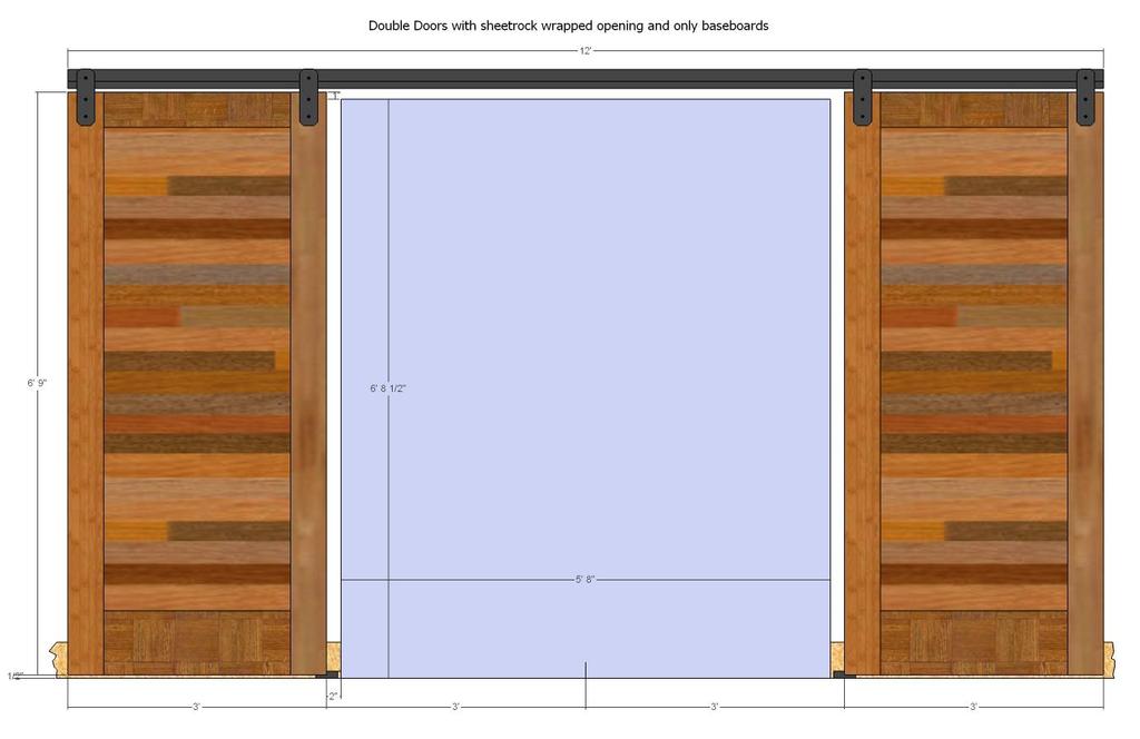
3 Page 3 of 9 obstructions for bolts to rub. Bolts will need to be countersunk into back of door or add spacers. The default setting to centerline of wheel is 7/8 from back of hanger. Move washers around on axle if necessary to have center of wheel from back of hanger plate to be half the thickness of your door so the door is centered front to back under the wheel. One can also adjust how well the door hangs plumb by moving the spacers on the axle, but make sure both wheel assemblies have equal number of washer spacers on both sides of wheel. If door is hanging to where bottom of door is leaning into the wall remove spacers between wheel and hanger. Floor guide will be necessary to make door hang plumb. Clearance under the door is recommended ½ - ¾ and must have a minimum of ¼. Over the top of the door slab 1 7/8 clearance is needed for wheel to spin freely. Sizing Sliding Door Slab to Finished Opening We recommend a minimum of 1 of overlap on all three sides. The drawings on the next page show 2 on sides, 1 on top, and ½ gap under door for demonstration purposes. More overlap ensures the door will cover the opening better and not allow as much gap to show around the edges even if not shut fully. To calculate door slab width on single door add overlap on side times two plus inside dimension of opening. To calculate door slab width on pair of doors take half of inside dimension width and add one side of overlap dimension for each door slab. Typically the track length is twice the width of the door. Sizing doors in increments that work exactly with standard track length makes the process simpler such as using a 3' door with a 6' track.

4 Page 4 of 9 To calculate door slab height take inside opening height subtract desired gap under door and add desired overlap on top. This could place the track over any trim that is over the top of the opening. Either the door slab needs to be adjusted in height so track can go above trim or trim needs to be flat and fully extend for full width under track so track can be mounted on trim. Note all these dimension are easier to calculate if opening is just a sheetrock opening with no trim. You need to consider what the trim will look like with door in open and closed position. How much of the trim do you want showing if any at all? For door height be sure to consider where the mounting lags need to go for mounting the track to the wall. They will be centered about 1 3/16" over top of door slab. Be sure there is proper backing and load support for lags to attach to at these points.

5 Page 5 of 9

6 Page 6 of 9 Installation Steps 1. Decide how you want the floor guide to be installed. If you want the alternative option shown in picture with double guides, be sure to order an extra floor guide. Otherwise cut a 1/4 wide kerf centered in bottom of door. To determine depth of kerf cut, subtract desired gap under door from 1 and add 1/16, so for a ½ gap under door you would have a 1/4 wide and 9/16 deep slot/ kerf. This is easiest to do with a router and a slot cutter. Have vertical part of floor guide centered in the same plane as the door for setting distance off wall. Be sure to reference off same point on the wall plane that track is mounted on; do not reference off face of baseboard. The points need to be aligned or door will not hang plumb. Center of door and center of vertical part on floor guide need to align. To find that vertical center point of door measure from back of door to wall and add half the thickness of the door. If floor guide s screws are going into material other than wood such as concrete in the floor, you will need to use different and appropriate fasteners. On a single door the guide is centered on the track from left to right. In any case, the door needs to cover at least half the floor guide whether it is in the full open or fully closed position. Install the floor guide to the floor. If the door properly overlaps the opening, then the floor guide should not protrude into the opening. 2. If you mount centerline/bolt holes of carriers 2 3/8 in from edge of door, this will have edge of door stop flush at end of track based on predrilled stop holes in track. The stop bolt hole is drilled 1 1/2 in from end of track to center of hole. Utilizing our predetermined pattern plywood spacer block (only works with rectangular shaped hanger) with edges of carrier 1 1/8" from edge of door (bolt holes 2 3/8" from edge of door is center of carrier) will allow for a track to work that is exactly twice the dimension of the door slab. Here is a formula you can plug in different values if you like to calculate track length: (Door Width) + (Distance From End Of Track To Center Of Stop Bolt Hole) - (Distance From Edge Of Door To Center Of Carrier) = Track Length / 2 For double doors on a single piece of track just don t divide the formula by 2 at the end.
7 Page 7 of 9 You can plug different scenarios into the above formula to calculate all different options to make the track work for your door size. The 5/16 stop hole can be re-drilled in another spot if would like to change mounting points or have door stop in different spot on track. For example you could redrill 5/16 holes 3/4 in from end of track and still mount carriers 1 1/8 in from edge of door; this would allow you to use a 48 ¾ door with an 8 track ( = 96 / 2); with this option your door would stick past the end of the track ¾. Also you could mount the carriers to center of carrier and utilize an 8 track for a 50 wide door without changing stop holes ( = 96 / 2). Make sure to consider how the carriers will look in relation to the frame on the door regardless of where you choose to mount them. On double doors with a single track you can also add extra stop bolts in center of track to make sure doors stop in the middle. Make sure complete carrier/hanger assembly is assembled with wheel, spacers and hanger. Normally the distance from back of hanger to center of wheel is approximately half the thickness of the door. Refer to the cross section drawing on page #3. Be sure to have the bolt that is the wheel axle in the appropriate hole. This hole is 3/4" from the top of the hanger. The washer that goes under the 3/8 acorn nut on the front of the hanger is the same size as the washer supplied with the two pair of mounting bolts used to mount the hangers to the door. Using supplied plywood guides, flush one piece up against edge of door to get distance of 1 1/8 from edge of door to edge of carrier bracket (only works with rectangular shaped hanger) and the other piece flat against top of door. Then hold complete assembled carrier with wheel attached tight to edge of piece on face of door and wheel tight to piece flat on top of door. The dimension from bottom of wheel to top of door is critical that it stays this recommend gap of 1/4 (the thickness of the plywood). This is a safety and proper functioning issue. This gap makes sure that the door and carrier assembly fit on track properly, slide smoothly, and do not jump off track. Holding these three pieces secure, temporarily clamp carrier/ hanger assembly to door making sure to leave two bolt holes clear. Make sure to have wheel side of carrier facing to center of door and verify that carrier s metal strap is square to door. Use 3/8 drill bit to drill both mounting holes in the door slab using the steel carrier plate as a guide. Be sure to drill straight and perpendicular to door face. Now repeat procedure for the other side. NOTE: The above step for using the plywood guide on the face of the door will not work with the arrow, horseshoe, or any custom shaped carriers; With these just measure from edge of door 2 3/8 to center of bolt holes or whatever you decided would be your centerline. You must still use the plywood spacer to set wheel height above door, though. NOTE: You can order track that is any length you want even though the rule of thumb is twice the door width. If you don t have room for this, and you have made all the adjustments you can by moving carriers and end stops then the door just won t fully open from closed position on too short of a track. Alternatively you can order track longer than you need if it helps with finding better attachment points for mounting lags; the end stops can be reinstalled to stop the door short of where it normally has the door edge flush with end of track. If the track is ordered and installed too long between stops (twice the door width) the floor guide won t function properly. In this case you may want to order and install multiple floor guides so the door slab does not jump off a floor guide in the situation where the travel distance for the door is greater than twice the door s width. NOTE: Washers on axle can be moved behind or in front of wheel to change clearance from wall for relationship distance of back of hanger/ carrier to center of track and wall. This also
8 Page 8 of 9 can help adjust a door to hang more plumb. Be careful that floor guide is centered front to back on door if you make any adjustments in the axle assembly. 3. At this point you may want to consider painting, staining, or finishing your door slab if necessary. Allow proper curing before handling door. 4. Determine distance from floor to top of track by adding gap under door + height of door slab + 1 5/8 (reference drawing at beginning of instructions). This top of track mark will line up with vertical top piece on back of track that mounts to wall. Mark this measurement on wall on each end of track location. Verify and adjust if need be with a level. Mark where end of track will be. This top of track mark is not the top of the wheel; the top of track is slightly lower than the top of the wheel. Note you want track installed level, but floor may not be level. Verify height points from floor along full length of track to be sure you have proper clearance. Keep track level and raise height if need be to get clearance. Also be sure that floor guide will reach door properly after setting height of track. If you have solid, structural, and continuous backing for the full length of the track then you can evenly space the mounting holes for the lag screws. Otherwise, locate all mounting points within full length of track on wall. Use stud finder if need be and mark each point on wall that is going to be a mounting point. With extra set of hands hold track up against wall and transfer mounting hole marks to track. If you cannot hold track up against wall, measure from one constant end to each hole. We recommend a minimum of five lags per section of track and spacing of around 16. Before drilling track be sure that you are drilling in the correct leg of the track that is supposed to be mounted to the wall. Both legs look similar. The bottom of the track has the stop bolt hole closest to it. The section that you will drill for the wall lags is furthest from the stop bolt holes. Drill 1/4" diameter holes from backside of track so you do not mar the finish. It is best to start hole with a steel punch for ease of starting drill bit. Center holes 3/8 down from top of track (reference drawing at beginning of instructions). Remember all mounting holes need to be in structural support. With drilled track verify it matches mounting points mark on wall. Install lag in each end of track (if installing by yourself it might be easier to mount one lag in the center of track instead of each end); be sure top of track mark on wall lines up with top of track. Note longer length tracks might be bowed. As you install the lags you can take this bow out of them. Be sure that your top of track marks on wall are straight and level; be sure to mount the track to these marks. Do not install track with any bow left in it. Now you can predrill with 1/8 bit all holes and install all lag screws checking to be sure track is still straight and level with each hole.
9 Page 9 of 9 Install stop with 5/16 x ½ button head bolt and acorn nut in one end of track. Be sure head of bolt faces down and acorn nut faces up in valley that wheel rides. Leave most accessible side of track open. 5. Bolt carrier with 3/8 bolts to door. Use acorn nuts on front, carrier side of the door. If you have clearance issues in the back you may need to cut bolts shorter or substitute so they work with acorn nuts. Normally the bolts sent with your kit are 1/2" longer than the thickness of the door. If you tell us in advance in your comments on checkout that you intend to countersink the bolts, we can substitute shorter bolts that are only 1/4" longer than the thickness of your door. 6. Now for the fun! Slide door onto track on free end of track without stop bolt. Install other stop bolt. If the end of the track is not accessible, take the wheel and axle off the carrier assemble, set door in front of track, and re-attach wheel and axle with spacers onto back of hanger plates after door is sitting in position at correct height below track. Do not slide or operate door without both stop bolts installed in each end of track. 7. Congratulations; you did it! Enjoy. It will last a long time. Please tell your friends where you bought this innovative low clearance track kit.
RLP Flat Track Hardware sliding door hardware/ barn door track
 Page 1 of 9 Installation Suggestions for: RLP Flat Track Hardware sliding door hardware/ barn door track Read these instructions to end before starting installation or ordering hardware. Reclaimed Lumber
SINGLE TRACK BYPASS (patent pending) barn door hardware
 barn door hardware") SINGLE TRACK BYPASS (patent pending) barn door hardware Installation Manual What is included in your kit: Part number Part name Quantity 1 Inner door hanger 2 2 Outer door hanger 2 3 5/16 x 1.5 lag bolts
SINGLE TRACK BYPASS (patent pending) barn door hardware Installation Manual What is included in your kit: Part number Part name Quantity 1 Inner door hanger 2 2 Outer door hanger 2 3 5/16 x 1.5 lag bolts
INS T A L L A TIO N INS T R U C TIO N S HORSESHOE W/ BAR HANGER
 INS T A L L A TIO N INS T R U C TIO N S HORSESHOE W/ BAR HANGER 6-1/2" 5" 2-7/16" 3-7/16" Ø2-7/8" 4-7/8" 11" 2" 3/16" 1/2" HORSESHOE W/ BAR S P ECIFICATIONS PARTS AND TOOLS Tools Needed Tape Measure Pencil
Contour Hanger ASSEMBLY INSTRUCTIONS
 Contour Hanger ASSEMBLY INSTRUCTIONS CONTOUR HANGER Recommended Tools Drill with 1/8, 1/4, and 3/8 Drill Bits, 1-1/8 Forstner Bit or 1-1/8 Spade Bit, and Phillips Bit 9/16 and 5/8 Combination Wrench Socket
Industrial Hanger ASSEMBLY INSTRUCTIONS
 Industrial Hanger ASSEMBLY INSTRUCTIONS INDUSTRIAL HANGER Recommended Tools Drill with 1/8, 1/4, and 3/8 Drill Bits, 1-1/8 Forstner Bit or 1-1/8 Spade Bit, and Phillips Bit 9/16 and 5/8 Combination Wrench
Box Track INSTALLATION INSTRUCTIONS
 Box Track INSTALLATION INSTRUCTIONS BOX TRACK Recommended Tools Level Tape Measure Pencil Drill with 1/8, and 1/4, Drill Bits, Phillips Bit and Slotted Bit Socket Wrench with 9/16 Socket 9/16 and 5/8 Wrench
TWIG Hanger ASSEMBLY INSTRUCTIONS
 TWIG Hanger ASSEMBLY INSTRUCTIONS TWIG HANGER Recommended Tools Drill with 1/8, 1/4, and 3/8 Drill Bits, 1-1/8 Forstner Bit or 1-1/8 Spade Bit, and Phillips Bit 9/16 and 5/8 Combination Wrench Socket Wrench
PRODUCT: LOKI INSTALLATION INSTRUCTIONS. Product is covered by U.S. patents. For more information visit
 R INSTALLATION INSTRUCTIONS PRODUCT: LOKI CONFIGURATION: SINGLE DOOR MOUNT: GLASS MOUNT Product is covered by U.S. patents. For more information visit www.krownlab.com . TOOLS + MATERIALS REQUIRED TOOLS
Cellar Hanger ASSEMBLY INSTRUCTIONS
 Cellar Hanger ASSEMBLY INSTRUCTIONS CELLAR HANGER Recommended Tools Drill with 1/8 and 1/4 Drill Bits, 1-1/8 Forstner Bit or 1-1/8 Spade Bit, and Phillips Bit 9/16, 7/16, and 5/8 Combination Wrench Socket
Stag Hanger ASSEMBLY INSTRUCTIONS
 Stag Hanger ASSEMBLY INSTRUCTIONS STAG HANGER Recommended Tools Drill with 1/8, 1/4, and 3/8 Drill Bits, 1-1/8 Forstner Bit or 1-1/8 Spade Bit, and Phillips Bit 9/16 and 5/8 Combination Wrench Socket Wrench
JELD-WEN DesignGlide Barn Door Hardware System Installation (JII-90003)
") JELD-WEN DesignGlide Barn Door Hardware System Installation IMPORTANT INFORMATION CONTACT US For questions, feel free to contact us by phone or email: Phone: 1-(800)-JELD-WEN/1-(800)-535-3936 Email: customerserviceagents@jeldwen.com
JELD-WEN DesignGlide Barn Door Hardware System Installation IMPORTANT INFORMATION CONTACT US For questions, feel free to contact us by phone or email: Phone: 1-(800)-JELD-WEN/1-(800)-535-3936 Email: customerserviceagents@jeldwen.com
Straight Stringer Installation Instructions
 Straight Stringer Installation Instructions Floor-to-Wall Installation F L I G H T P L A N Unpack: What s included? Your Stringer Tread Screws (8) per tread (1) Torque Wrench (1) Socket (for the brackets
Pillar Hanger ASSEMBLY INSTRUCTIONS
 Pillar Hanger ASSEMBLY INSTRUCTIONS PILLAR HANGER Recommended Tools Drill with 1/8, 1/4, and 3/8 Drill Bits, 1-1/8 Forstner Bit or 1-1/8 Spade Bit, and Phillips Bit 9/16 and 5/8 Combination Wrench Socket
x2 1/4 (6mm) Floor Anchor
 Floor Anchor") INSTALLATION GUIDE Main Components x1 Rail x5 Wall Spacer x2 Anti-jump Block x2 Straight Strap x1 Right Stopper x1 Left Stopper x5 5/16 (8mm x 60mm) Carriage Bolt x5 5/16 (8mm x25mm) Anchor x5 5/16 (8mm
INSTALLATION GUIDE Main Components x1 Rail x5 Wall Spacer x2 Anti-jump Block x2 Straight Strap x1 Right Stopper x1 Left Stopper x5 5/16 (8mm x 60mm) Carriage Bolt x5 5/16 (8mm x25mm) Anchor x5 5/16 (8mm
INSTALLATION INSTRUCTIONS INS T A L L A TIO N INS T R U C TIO N S THE MAVERICK HANGER R H
 INS T A L L A TIO N INS T R U C TIO N S THE MAVERICK HANGER 10.6.2016 PARTS INSTALLATION SPECIFICATIONS AND TOOLS INSTRUCTIONS 2-1/4" 2-7/8 11-3/8" 1/4" 2-1/8 PARTS INSTALLATION AND INSTRUCTIONS TOOLS
Heavy-Duty Bypass Track System
 Heavy-Duty Bypass Track System Please Note: This track system must be installed with the screws going into a solid surface such as studs or a header. Due to the spacing of the holes on these Brackets,
LOFT DOOR HANGER BARN DOORS & HARDWARE. Hardware Installation Instructions. Page
 LOFT DOOR HANGER Page 1 Specifications 2 7/16" 3/8" 1-1/2 1-3/4 Ø3 3 7/8" 11-1/16 Page 2 Parts and Tools Tools Needed Tape Measure Pencil Drill with 1/8, 1/4 and 3/8 bits, 1 spade bit and Phillips bit
Ripple Hanger ASSEMBLY INSTRUCTIONS
 Ripple Hanger ASSEMBLY INSTRUCTIONS RIPPLE HANGER Recommended Tools Drill with 1/8, 1/4, and 1/2 Drill Bits, 1-1/8 Forstner Bit or 1-1/8 Spade Bit, and Phillips Bit 9/16 and 5/8 Combination Wrench Socket
Loft Hanger ASSEMBLY INSTRUCTIONS
 Loft Hanger ASSEMBLY INSTRUCTIONS LOFT HANGER Recommended Tools Drill with 1/8, 1/4, and 3/8 Drill Bits, 1-1/8 Forstner Bit or 1-1/8 Spade Bit, and Phillips Bit 9/16 and 5/8 Combination Wrench Socket Wrench
x2 1/4 (6mm) Floor Anchor
 Floor Anchor") Main Components x1 Rail x5 Wall Spacer x2 Anti-jump Block x2 Bent Strap x1 Right Stopper x1 Left Stopper x5 5/16 (8mm x 60mm) Carriage Bolt x5 5/16 (8mm x25mm) Anchor x5 5/16 (8mm x 90mm) Wall Screw x2
Main Components x1 Rail x5 Wall Spacer x2 Anti-jump Block x2 Bent Strap x1 Right Stopper x1 Left Stopper x5 5/16 (8mm x 60mm) Carriage Bolt x5 5/16 (8mm x25mm) Anchor x5 5/16 (8mm x 90mm) Wall Screw x2
WAREHOUSE HANGER INSTALLATION INSTRUCTIONS R H INS T A L L A TIO N INS T R U C TIO N S
 INS T A L L A TIO N INS T R U C TIO N S WAREHOUSE HANGER NOTE: Due to the size and weight of the Warehouse Hanger it is recommended that this Hanger be installed on 3 4 or wider doors. 10.11.2016 2-3/16"
INSTALLATION INSTRUCTIONS INS T A L L A TIO N INS T R U C TIO N S ROD IRON SCROLL HANGER R H
 INS T A L L A TIO N INS T R U C TIO N S ROD IRON SCROLL HANGER 10.5.2016 2-1- 3/16" 11/16" 8" 8 O 2-7/8 Ø2-7/8" 3-1/2 3-1/2" 12-9/16 12-9/16" PLEASE NOTE: These instructions are specific to a particular
Triple Bypass System
 Triple Bypass System ASSEMBLY INSTRUCTIONS TRIPLE BYPASS SYSTEM Recommended Tools Drill with 1/4 Drill Bit and Phillips Screw Bit 7/16 Combination Wrench Socket Wrench with 7/16 and 9/16 Socket Level Tape
BARN DOOR HARDWARE KIT
 INSTALLATION GUIDE Main Components x1 Rail x5 Wall Spacer x2 Anti-jump Block x2 Bent Strap x1 Right Stopper x1 Left Stopper x5 5/16 (8mm x 60mm) Carriage Bolt x5 5/16 (8mm x25mm) Anchor x5 5/16 (8mm x
Top Mount Ultra Modern Hanger
 Top Mount Ultra Modern Hanger ASSEMBLY INSTRUCTIONS TOP MOUNT ULTRA MODERN HANGER Recommended Tools Level Tape Measure Pencil Drill with 1/8, and 1/4, Drill Bits and Phillips Bit Socket Wrench with 9/16
INSTALLATION INSTRUCTIONS
 www.marwincompany.com Kit Number Door Height Rough Opening Height KD200BB68 80 84 ½ KD200BB70 84 88 ½ KD200BB80 96 100 ½ INSTALLATION INSTRUCTIONS 200BB SERIES KD POCKET DOOR FRAME FOR 2 X 4 STUD WALLS
Installation Manual Flat Track Series
 Manual Flat Track Series Contents Safety...1 Parts...2 Hardware.......................................... 2 Tools Required..................................... 4.............................................
Heavy Duty I-Beam Trolley
 Heavy Duty I-Beam Trolley ASSEMBLY INSTRUCTIONS I-BEAM TROLLEY Recommended Tools Level Tape Measure Pencil Drill with 1/8, 1/4, and 3/8, Drill Bits and Phillips Bit Socket Wrench with 9/16 Socket I-BEAM
Install Instructions. NewAge Steel Welded Tall Locker
 Kit Contains Full Width Adjustable Steel Shelves (4) Height-Adjustable Steel Leveling Legs (4) Aluminum Door Trim (2) 2.5 x ¼ Cabinet Mounting Lag Bolts (4) Large Zinc Plated Mounting Washers (4) 5/8 x
BD101K / BD101K INSTALLATION GUIDE BARN DOOR HARDWARE TOP OF DOOR STRAP KIT
 Common Components x1 Right Stopper x1 Left Stopper x2 Top of Door Strap x2 Anti-jump Block x2 #8 (4.2mm x 25mm) Floor Screws x2 1/4 (6mm) Floor Anchor x1 Internal Floor-Mounted Door Guide BD850-BR/MB/SS
Assembly Instructions 10 X 10 Aluminum Roof Support
 Assembly Instructions 10 X 10 Aluminum Roof Support Aluminum Roof Support Bolt Package 16-5/16 X 2 ¼ SS Bolt 24-5/16 X 1 SS Bolt 40-5/16 SS Nylon Lock Nuts 16-5/16 SS Flat Washers 28-4 ½ Wood Screws 36-1
Spoked GARRICK HANGER
 Spoked GARRICK HANGER ASSEMBLY INSTRUCTIONS SPOKED GARRICK HANGER Recommended Tools Drill with 1/8 and 1/4 Drill Bits, 1-1/8 Forstner Bit or 1-1/8 Spade Bit, and Phillips Bit 9/16 and 5/8 Combination Wrench
Installation Instruction
 Tools Needed for Assembly Stud finder (for wood stud wall) Pencil Mark Electric drill Wood Stud Wall Installation Step 1. Locate the Wood Studs Installation Instruction Drill bit (for wood stud wall) Masonry
INSTALL INSTRUCTIONS WELCOME TO THE NEWAGE PERFORMANCE CABINETRY SERIES NEWAGE STEEL WELDED CABINETRY
 NEWAGE STEEL WELDED CABINETRY WELCOME TO THE NEWAGE PERFORMANCE CABINETRY SERIES ALL CABINETS MUST BE MOUNTED TO STUDS ON A SECURE WALL, AS PER THESE INSTRUCTIONS. FAILURE TO DO SO MAY RESULT IN SERIOUS
Assembly Instructions 10 X 10 Aluminum Frame Building
 Assembly Instructions 10 X 10 Aluminum Frame Building 27 97 9 8 47 36 74 52 10 10 X 10 Square Building W/ Dome Includes: The Steel Entry Door with a Dead Bolt Lock assembly and Aluminum Door Frame. Metal
Rockwell 4-in-1 Sliding Door
 Rockwell 4-in-1 Sliding Door ASSEMBLY INSTRUCTIONS ROCKWELL 4-IN-1 SLIDING DOOR Recommended Tools Drill with Phillips Bit Socket Wrench with 7/16 Socket Rubber Mallet Adjustable Square ROCKWELL 4-IN-1
EmagiKit. Privacy Pod Plus. Quiet. Easy. Affordable. INSTRUCTIONS ASSEMBLY
 EmagiKit Privacy Pod Plus Quiet. Easy. Affordable. INSTRUCTIONS ASSEMBLY DIMENSIONS AND COMPONENTS 47 47 Ceiling Unit 2-B 2-L 2-R Glass Door Corner Trim Door Handle 90 Adjustable Height Work Surface 1-B
TP4463. ASSeMBly INSTruCTIONS FLAT PANEL TV MOUNTING SYSTEM OPTION 1 OPTION 2 OPTION 3
 TP63 FLAT PANEL TV MOUNTING SYSTEM OPTION 1 OPTION 2 OPTION 3 Flat Panel TV Stand Stand with TV Mounting System Stand with Wall Mount ASSeMBly INSTruCTIONS for your safety, please follow these precautions:!
ROCKWELL. Two Panel Door. Half X Door. Double X Door. Z Combination Door
 ROCKWELL 4 in 1 DOOR Choose between four door styles with this Door Kit. Our versatile Rockwell Door Kit is very easy to assemble. All materials and hardware needed to assemble any of the four styles are
1. VERIFY ALL COMPONENTS
 R INSTALLATION INSTRUCTIONS RAGNAR+ODEN FACE MOUNT, BYPASSING. VERIFY ALL COMPONENTS BASE KIT Track stand-offs Front trolley kit * Rear trolley kit * Allen keys Track fastener kit - wood - Bottom guide
INS T A L L A TIO N INS T R U C TIO N S. Ceiling Mount Track System
 Ceiling Mount Track System 10.26.2016 Specifications Ceiling Post: Unassembled 2-7/8 Assembled 1-11/16 7/8 7-9/16 5-7/8 3/8 2 Tubes 1/2 2-3/8 5 Parts and Tools Tools Needed Tape Measure Pencil Drill with
ATLANTIS RAIL Contact Information
 ATLANTIS RAIL Contact Information Customer Service (800) 541-6829 (508) 732-9191 Spectrum System Installation Instructions Atlantis Rail s Spectrum System is an easy to install, universal cable railing
1. TOOLS + MATERIALS REQUIRED
 R INSTALLATION INSTRUCTIONS PRODUCT: BALDUR + ODEN CONFIGURATION: BI-PARTING DOOR MOUNT: TOP MOUNT Product is covered by U.S. patents. For more information visit www.krownlab.com. TOOLS + MATERIALS REQUIRED
INSTALLATION INSTRUCTIONS VENETIAN 84" SLIDING SHOWER DOOR SYSTEM (180º INSTALLATION)
") INSTALLATION INSTRUCTIONS VENETIAN 84" SLIDING SHOWER DO SYSTEM (180º INSTALLATION) 28539 Industry Drive, Valencia, CA 91355 Toll Free Phone: (877) 728-3874 Toll Free Fax: (888) 440-9567 Phone: (661) 775-1675
INSTALLATION INSTRUCTIONS VENETIAN 84" SLIDING SHOWER DO SYSTEM (180º INSTALLATION) 28539 Industry Drive, Valencia, CA 91355 Toll Free Phone: (877) 728-3874 Toll Free Fax: (888) 440-9567 Phone: (661) 775-1675
ICU TRACKLESS SLIDING DOOR
 Interior View 0 Installation Instructions Tools Required: Screwdrivers Small Straight (Flat Blade) - for Terminal Block wiring # Phillips (Crosspoint) - for various #8, #0, and #4 screws Wrenches / Sockets
PRODUCT: BALDUR + ODEN
 R INSTALLATION INSTRUCTIONS PRODUCT: BALDUR + ODEN CONFIGURATION: SINGLE DOOR MOUNT: GLASS MOUNT Product is covered by U.S. patents. For more information visit www.krownlab.com . TOOLS + MATERIALS REQUIRED
86-1/2" TRACK INSTALLATION GUIDE
 BARN TRACK 86-1/2" TRACK INSTALLATION GUIDE READ ALL INSTRUCTIONS AND REVIEW DIAGRAMS BEFORE BEGINNING THE INSTALLATION TO GET A THOROUGH UNDERSTANDING OF THE PROCESS. BEFORE YOU BEGIN This kit comes with
48 in. X 96 in. 500 Pound Capacity Motorized Overhead Storage Unit Option A
 48 in. X 96 in. 500 Pound Capacity Motorized Overhead Storage Unit Option A MODEL # PRM4X8 Patent Pending 1 Table of Contents Table of Contents PAGES Installation Support 3 Safety Information 4-5 Required
Required Tools: Suggested Additional Tools: 1 Cordless Drill with Robertson Bits 1 Ratchet Wrench 1 7/16 or 11mm socket 1 7/16 or 11mm Gear Wrench
 Thank you for your recent purchase of a Cabinets by Hayley garage cabinet system. You are about to experience the best made cabinets that you can purchase. Cabinets by Hayley are designed for beauty and
Why are we giving this guidebook as a FREE download?
 Construction Guide Queen, Double & Twin Vertical 1 Note: This guide covers the construction steps for all 3 sizes of the vertical wall mount Easy DIY Murphy beds, Queen, Double and Twin. The construction
48 in. X 96 in. 500 Pound Capacity Motorized Overhead Storage Unit Option B
 48 in. X 96 in. 500 Pound Capacity Motorized Overhead Storage Unit Option B MODEL # PRM4X8 Patent Pending 1 Table of Contents Table of Contents PAGES Installation Support 3 Safety Information 4-5 Required
Important Note: Why this guidebook is FREE?
 Easy DIY Murphy Bed Construction Guide 1 Important Note: This guide is a FREE SAMPLE of our Complete Construction Guidebook. With the help of this guide you will get familiar with the construction steps
ROCKWELL 4-IN-1 DOOR. Two Panel Door. Half X Door. Z Combination Door. Double X Door
 ROCKWE 4-IN-1 DOOR Two Panel Door Half X Door Double X Door Z Combination Door Choose between four door styles with this Door Kit. Our versatile Rockwell Door Kit is very easy to assemble. All materials
Video Wall Installation Instructions 2W X 3H, 3W X 3H
 Video Wall Installation Instructions 2W X 3H, 3W X 3H www.microndisplaysolutions.com Table of Contents Important Safety Instructions... 3 Configuration... 4 Package Contents, included and optional items...
GlideRite Retractable Cover System For Hot Spot Spas (SE & SLX only)
") List of Contents Quantity Description 12 #10 x 1 ½ Flat Head Phillips Screw (see pg. 2) 2 #10 x ½ Pan Head Phillips Screw (see pg. 2) 8 ¼ x 2 ½ Lag Bolt (see pg. 2) 7 ¼ 20 x 5 / 8 Hex Head Bolt (see pg.
List of Contents Quantity Description 12 #10 x 1 ½ Flat Head Phillips Screw (see pg. 2) 2 #10 x ½ Pan Head Phillips Screw (see pg. 2) 8 ¼ x 2 ½ Lag Bolt (see pg. 2) 7 ¼ 20 x 5 / 8 Hex Head Bolt (see pg.
Barn Door & Hardware Installation Guide
 Barn Door & Hardware Guide INTRODUCTION Thank you for purchasing our hardware. Our barn door and hardware will add a stunning accent to your living environment and maximize its space. This manual covers
Vinyl Gazebo Instructions
 P a g e 1 Vinyl Gazebo Instructions 10 Vinyl Gazebo Shown Thank you for the purchase of your New Gazebo. Depending on the size of your Gazebo, installation can usually be completed in 1 to 2 days. These
DX-TVMLPTB03. Low-Profile TV Wall Mount ASSEMBLY GUIDE. For either wood-stud or concrete wall installations
 ASSEMBLY GUIDE DX-TVMLPTB03 Low-Profile TV Wall Mount For either wood-stud or concrete wall installations Safety information and specifications...2 Tools needed...........................3 Package contents......................3
Sliding Door Kit
 YOU MUST READ THIS DOCUMENT BEFORE YOU BEGIN TO ASSEMBLE THE DOOR KIT. Thank you for purchasing this GrowSpan door kit. When properly assembled and maintained, this product will provide years of reliable
GlideRite Retractable Cover System For HotSpring & Tiger River Spas (except Classic & pre-2000 Landmark Spas)
") List of Contents Quantity Description 12 #10 x 1 ½ Flat Head Phillips Screw (see pg. 2) 2 #10 x ½ Pan Head Phillips Screw (see pg. 2) 8 ¼ x 2 ½ Lag Bolt (see pg. 2) 7 ¼ 20 x 5 / 8 Hex Head Bolt (see pg.
List of Contents Quantity Description 12 #10 x 1 ½ Flat Head Phillips Screw (see pg. 2) 2 #10 x ½ Pan Head Phillips Screw (see pg. 2) 8 ¼ x 2 ½ Lag Bolt (see pg. 2) 7 ¼ 20 x 5 / 8 Hex Head Bolt (see pg.
Chapter 18. Interior Doors
 Chapter 18. Interior Doors 18.1 SWINGING DOORS 18.2 SLIDING DOORS 18.3 BIFOLD DOORS Tools needed by volunteers: Hammer Nail apron Tape measure Square Pencil Tools and equipment needed: Extension cords
Plans. Easy-to-Build Full-size Deluxe Murphy Bed Plan. For more plans, tools and hardware visit rockler.com
 Easy-to-Build Full-size Deluxe Murphy Bed Plan Build a full-size Deluxe Murphy Bed complete with decorative molding and matching side cabinets! Plans For more plans, tools and hardware visit rockler.com
Agave Standard Series
 Mailing Address: 033 San Elijo Ave, #464 Cardiff, CA 9007 619.708.917 619.330.88 fax info@agaveiron.com www.agaveiron.com Agave Standard Series Flat Track Hardware Systems General Information and Installation
CABINET INSTALLATION INSTRUCTIONS
 CABINET INSTALLATION INSTRUCTIONS Please read these instructions through completely before beginning the installation. Thank you for choosing Plato Personalized Custom Cabinetry for your home. Your Plato
Murphy Door DIY Hardware Installation Manual
 Murphy Door DIY Hardware Installation Manual The Murphy Door Bi-Folding Bookshelf was designed to install IN FRONT of existing door ways, replacing the door or doors while concealing the door way. In MOST
Chapter 1. Beam and Sill Plates
 Chapter 1. Beam and Sill Plates 1.1 ESTABLISHING SQUARE SILL PLATE CHALK LINES 1.2 INSTALLING TREATED SILL PLATES 1.3 INSTALLING LAMINATE BEAM Tools needed by volunteers: Hammer Nail apron Tape measure
ASSEMBLY INSTRUCTIONS FOR HAULER II SERVICE BODY A RACK
 ASSEMBLY INSTRUCTIONS FOR HAULER II SERVICE BODY A RACK T12USBA-1 shown above Package Contents: HARDWARE KIT PARTS (4) 3/8-16 x 3 CARRAIGE BOLTS (1) RAIL DRIVER S SIDE ASSEMBLY (20) 3/8-16 x 2 CARRAIGE
48 in. X 96 in. 500 Pound Capacity Motorized Overhead Storage Unit Installation Guide [OPTION B] MODEL # PRM4X8 Patent Pending
![48 in. X 96 in. 500 Pound Capacity Motorized Overhead Storage Unit Installation Guide [OPTION B] MODEL # PRM4X8 Patent Pending](/thumbs/81/83353561.jpg "48 in. X 96 in. 500 Pound Capacity Motorized Overhead Storage Unit Installation Guide [OPTION B] MODEL # PRM4X8 Patent Pending") 48 in. X 96 in. 500 Pound Capacity Motorized Overhead Storage Unit Installation Guide [OPTION B] MODEL # PRM4X8 Patent Pending 1 Table of Contents Table of Contents PAGES Installation Support 3 Safety
48 in. X 96 in. 500 Pound Capacity Motorized Overhead Storage Unit Installation Guide [OPTION B] MODEL # PRM4X8 Patent Pending 1 Table of Contents Table of Contents PAGES Installation Support 3 Safety
Wallbeds Northwest ENDURA CABINET PLANS AND INSTRUCTIONS
 Thank you for purchasing your Wall Bed from Wallbeds Northwest. If you have purchased a complete "Endura DIY Kit," then much of the work is already done for you. Please skip to assembly instructions. Note
Frameless Fixed Panel Slider
 INSTALLATION INSTRUCTIONS Frameless Fixed Panel Slider QCI-5279 SINGLE ROLLER WITH ANTI-JUMP DOUBLE ROLLERS QCI5279 Rev Page Certified 08/09/6 Tools: To install your New Shower Enclosure, you may need
Hardware Box 1 1/4 Diameter x 3/4 Long Bolts 24 1/4 Nylon Lock Nut 24 1/4 Diameter x 3 Long Lag Bolt 8 1/4 Washers 56
 Warning: Excessive weight hazard! Use two or more people to move, assemble or install overhead rack to avoid back or other injury. Do not leave children unattended near overhead rack. High risk of injury
FOLDING DOOR - FOR FACTORY ASSEMBLED JAMBS WITH APPLIED SILL
 FOLDING DOOR - FOR FACTORY ASSEMBLED JAMBS WITH APPLIED SILL READ SPECIFIC INSTALLATION INSTRUCTIONS COMPLETELY BEFORE STARTING ANY INSTALLATION Failure to install and maintain our product according to
Chapter 23. Garage Construction
 Chapter 23. Garage Construction 23.1 ESTABLISHING CHALK LINES 23.2 MEASURING AND CUTTING WALL PLATES 23.3 MARKING WINDOW & DOOR LOCATIONS ON EXTERIOR WALL PLATES 23.4 MARKING STUDS ON EXTERIOR WALL PLATES
M10 x 75mm Sockethead Cap Screws. 5mm Fender Washer (12) Included - (8) Required. #10 x 2.5" PH Wood Screws. (30) Included - (24) Required
 Included - (8) Required. #10 x 2.5 PH Wood Screws. (30) Included - (24) Required") Door System Unit - Hardware Tools Included: (2) 2mm Allen Wrenches, (2) 3mm Allen Wrenches, (2) 4mm Allen Wrenches, (2) 6mm Allen Wrenches, and (1) 8mm T-Handle Allen Wrench Tools Required: Phillips Screwdriver,
Door System Unit - Hardware Tools Included: (2) 2mm Allen Wrenches, (2) 3mm Allen Wrenches, (2) 4mm Allen Wrenches, (2) 6mm Allen Wrenches, and (1) 8mm T-Handle Allen Wrench Tools Required: Phillips Screwdriver,
1 PREPARE HEADER AND ROUGH OPENING
 CONTENTS. HEADER & TRACK ASSEMBLY. END BRACKET PLAIN 3. FLOOR PLATE.. 8. 4. SPLIT STUD 6 5. CARRIER (987) 6. QUICK RELEASE PLATE (960) 7. DOOR GUIDE SET (9883) 3. 4. 7. 8. BUMPER KIT (988) 9. #8 X 3/4
BASE & WALL CABINET SETUP GUIDE BY SUNSTONE
 BASE & WALL CABINET SETUP GUIDE BY SUNSTONE Read all instructions before you install cabinet. Very important to follow each step in order as detailed in this Instruction Guide!!! To installer or person
Woodline USA Woodline Spacer Fence System
 Woodline USA Woodline Spacer Fence System MADE IN THE USA Includes: (1) ¼ Spacer Fence (1) 3/8 Spacer Fence (1) ½ Spacer Fence (1) Hardware Package (1) 3 Piece Brass bar set (2) Setup Blocks Visit Us Online
VACUSEAL MODEL 200. HOT TUB PRODUCTS 233 Carrington Road Bethany CT
 VACUSEAL MODEL 200 J G F G H L HOT TUB PRODUCTS 233 Carrington Road Bethany CT 06524 860-469-2580 www.vacusealcoverlift.com www.hottubproducts.com Made in USA H K E D C I A P B 10 9 8 7 6 5 4 3 2 1 0 SPAS
Desk/Wall-Mount Rack
 Desk/Wall-Mount Rack Patent(s) Pending Installation Instructions Post P/N: 119-1752 119-1781 119-1782 119-4014 Frame P/N: 119-1591 119-1754 119-1755 Kit Contents (2) Frames (4) Posts Assembly Hardware
ICU TRACK SLIDING DOOR
 Interior View 0 Installation Instructions Tools Required: Screwdrivers Small Straight (Flat Blade) - for Terminal Block wiring # Phillips (Crosspoint) - for various #8, #0, and # screws Wrenches / Sockets
Motorized or Crank Operated Fortress Zipper Track Shade with Housing and Side Track Installation Instructions
 Motorized or Crank Operated Fortress Zipper Track Shade with Housing and Side Track Installation Instructions Tools Needed Drill 3/8 Metal Drill Bit ¼ Masonry Drill Bit Measuring Tape Pencil 4 Level Phillips
Installation Instructions
 Supafold Slide Aside System Three Fold Room Divider Installation Instructions Distinctive Doors Ltd Supafold Slide Aside Internal Folding System IMPORTANT: Before proceeding with the installation, and
4. Components and Stairs
 4. Components and Stairs 4.1 BUILDING WINDOW AND DOOR COMPONENTS 4.2 BUILDING STAIRS Tools needed by volunteer: Hammer Nail apron Tape measure Square Utility knife Pencil Tools and equipment needed: Materials
IDP Entry-Fit Steel Door Frames. Installation Instructions K2A and NK2A Series Frames
 IDP Entry-Fit Steel Door Frames Installation Instructions K2A and NK2A Series Frames IDP Inc 21300 W. 8 Mile Rd. Southfield, MI 48075 1-877-645-2770 www.idpframes.com email: info@idpframes.com K2A and
MONKEY BARS OVERHEAD RACK INSTALLATION
 MONKEY BARS OVERHEAD RACK INSTALLATION Thank you for purchasing the New Monkey Bars Overhead storage rack. The most innovative overhead rack on the market WARNING THE PROPER INSTALLATION OF THIS STORAGE
FIXED PANEL SLIDER QCI5241
 INSTALLATION INSTRUCTIONS FIXED PANEL SLIDER QCI5241 FRAMELESS PANEL / DOOR / PANEL FRAMELESS DOOR / PANEL QCI5241 REV. 0 Page 1 Certified 06/16/2016 Parts List *Quantities may vary QCI5241 REV. 0 Page
Wagon Vise Retrofit Installation Instructions. American Craft Woodworks. Wagon Vise
 Wagon Vise Retrofit Installation Instructions American Craft Woodworks Wagon Vise Wagon Vise Retrofit Installation Instructions 2 Retrofit Installation Instructions Before you get started, please read
ADULT ASSEMBLY REQUIRED
 ADULT ASSEMBLY REQUIRED If you have any questions regarding assembly or if you are missing parts, do not return this item to the Retailer Store Please call our customer service number and have your instructions
INSTRUCTION BOOKLET #34. For Wallbed models: KING SIZE SIERRA WITH STORAGE HEADBOARD
 For Wallbed models: KING SIZE SIERRA WITH STORAGE HEADBOARD INSTRUCTION BOOKLET #34 WARNING! ALL MURPHY/WALLBED SYSTEMS CONTAIN STORED ENERGY. FAILURE TO USE AND FOLLOW THESE INSTRUCTIONS DURING THE INSTALLATION
AWNING / PATIO COVER INSTALLATION INSTRUCTIONS
 AWNING / PATIO COVER INSTALLATION INSTRUCTIONS Before You Begin Read the installation instructions thoroughly before beginning the installation procedure. Perspective In the Awning Instructions, Back means
IF INSTALLING ANY OF THE PORTMAN SELF CLOSING SYSTEMS, PLEASE READ THE CORRESPONDING FITTING INSTRUCTIONS SUPPLIED WITH THE CLOSING SYSTEM FIRST
 Set A Set B PFD60 Fire Door Kit FITTING INSTRUCTIONS IF INSTALLING ANY OF THE PORTMAN SELF CLOSING SYSTEMS, PLEASE READ THE CORRESPONDING FITTING INSTRUCTIONS SUPPLIED WITH THE CLOSING SYSTEM FIRST SUGGESTED
southpaw enterprises, inc.
 Store these instructions in a safe place or with the enclosed maintenance checklist In-FUN-ity Climbing System Assembly Examples This example sheet is intended to supplement the instruction sheets that
SMARTfit Functional and Brain Fitness Training Multi-Station Trainer Installation for Stud and Concrete Walls (US)
") SMARTfit Functional and Brain Fitness Training Multi-Station Trainer Installation for Stud and Concrete Walls (US) 2017 SMARTfit, Inc. www.smartfitinc.com 1 Unlike other fitness equipment which may require
SMARTfit Functional and Brain Fitness Training Multi-Station Trainer Installation for Stud and Concrete Walls (US) 2017 SMARTfit, Inc. www.smartfitinc.com 1 Unlike other fitness equipment which may require
ESA-200 Fixed Sidelite
 Exterior View Installation Instructions For use with ESA II Controller 1 Tools Required: Suggested Fasteners Required - (Not supplied) Screwdrivers Small Straight (FlatBlade) - for Terminal Block wiring
Extra Wide Heavy Duty Plastic Lockers Series Locker Installation Instructions
 Locker Installation Instructions Thank you for selecting Extra Wide Heavy Duty Plastic Lockers. We are confident that the quality and construction of the lockers will prove to be a good investment. These
Assembly InstructIons
 tp50 FLAT PANEL TV MOUNTING SYSTEM OPTION OPTION 2 OPTION 3 Flat Panel TV Stand Stand with TV Mounting System Stand with Wall Mount Assembly InstructIons for your safety, please follow these precautions:!
Aluminum Sprinter Rack Installation
 INSTALLATION INSTRUCTIONS MyGlassTruck.com Division of Demountable Concepts, Inc Aluminum MyGlassTruck.Com Demountable Concepts, Inc. 200 Acorn Rd. Glassboro, NJ 08028 800.254.3643 toll free 856.863.0900
Assembly Instructions
 10' and 12' Octagon Cedar Gazebo Assembly Instructions Toll Free: 866.768.8465 Hours: 9-5 Monday-Friday EST www.homeplacestructures.com Package ships as shown revised 06/20/09 Cedar Gazebo Assembly Instructions
SLIDING MECHANISM TROLLEY CATCH TROLLEY ASSEMBLY FLOOR GUIDE
 Set A Set B PFD30 Fire Door Kit FITTING INSTRUCTIONS For use with 44mm thick doors only For Single and Double doors IF INSTALLING A TOUCH LATCH, PLEASE READ THE CORRESPONDING FITTING INSTRUCTIONS FIRST
ASSEMBLY INSTRUCTIONS FOR SERVICE BODY A MOUNT RACKS
 ASSEMBLY INSTRUCTIONS FOR SERVICE BODY A MOUNT RACKS T12 Service Body A shown with optional middle crossbar Package Contents: HARDWARE KIT PARTS (8) 3/8-16 x 3 CARRAIGE BOLTS (1) RAIL DRIVER S SIDE ASSEMBLIES