Norman's Grizzly G0602 Reverse Tumbler Plans
|
|
|
- Marybeth Short
- 5 years ago
- Views:
Transcription

1 Norman's Grizzly G0602 Reverse Tumbler Plans Pictures taken by Norman Author Norman here is the photos of the change gears for the G0602 lathe. reverse turning to the right or for left hand threads netural gear train stops completely forward or turning to the left

.")
2 unfinished gear selector lever. its not pretty but it works fine. I still have things to do to finish it all up. x 4" plate for the plastic gear 60 tooth mount. I machined a new mounting stud instead of using the metric mounting stud. This mounting stud has 1/4-20 threads the shoulder is also larger in dia. around 5/8". I added a plate mounting bolt 1/4-20 flush head by the gear stud after this photo was shot plus cut off the excess mounting plate right at 1/2" below the gear mount stud. I used the stock hole for mounting the plate it's a metric thread, used a flush head machine screws for both, the bottom is a - 20 thread(not shown). back side of the tumbler plate the milled area is so the plate will partly go over the stock metric plate(its thicker than the plate) and not allow the plate to pivot any farther towards the back. I welded on
 engine.")

3 the lever arm to the gear plate and bushed the pivot hole this plate will mount on the first plate using the new gear stud's 5/8" dia shoulder. front side you can see the gears are not parallel that is so only one gear at a time is in contact with the spindle gear. the gears are cut down timing gears from a small (5hp) engine. You will need to heat them up to glowing red/orange then let them cool slowly so you can machine them. both gears need bored to fit the roller bearings then machine the gears to around 3/8" width. I used 1/8" pipe machined down to fit the I.D. of the bearings. Then I used small dia washers on each side of the 1/4-20 mounting bolts. To set the proper mesh for the gears I used writing paper between the gears. Then center punch the spots to drill and tap the 2 holes for1/4-20" threads lever mount made from cold roll steel mounted with 1/4-20" bolts. once I was satisfied with the tumbler gears mesh. I took the plate off and tack welded a top and bottom limit plate again made from plate. The forward neutral and reverse plate is 5/8" key stock this is mounted to the lathe with 2 1/4-20 flush head machine screws. I checked behind the lathes control cover plate first to make sure I didn't drill onto any thing important for the 2 1/4-20 bolts


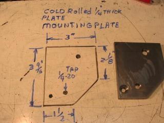
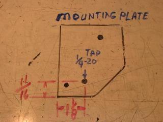
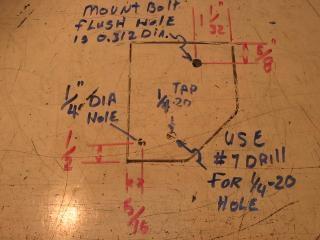
4 I also welded a 5/8x5/8x 1"(5/8" sq. key stock) square block the end of the lever to mount the spring loaded switching pin. I used the bench grinder to round the corners off a little on the welded on lever end. I still need to cut the lathes cover for all this to fit and make a knob for the levers threaded end. To switch the lever pull out on the knob and select the position you want, the lever will index into 1 of 3 holes forwards, neutral, and reverse. I made a knob for the lever out of a brass spruce from one of my attempts at casting brass so I'll show that once I take a photo of it. This is the first thick plate the blue circle is the metric shoulder bolt mount, now used as the plates mounting bolt. Both mounting bolts are flush head machine screws. The black arrow points to the other mounting spot using a 1/4-20 flush machine screw. You can also see the shoulder bolt for the 60 tooth plastic gear. The thing in the left front is my speed reducer, I didn't bother to remove it while I took the reverse tumbler apart for show and tell. This is the plate's measurements. Your measurements may be different.
5


6 same plate with the mounting hardware. Instead of using the metric shoulder bolt I made this one from cold rolled steel. the shoulder is round( dia.) and the wrenching flats are on the bolts end the length is longer than the stock shoulder bolt. It's drilled for one of those spring ball oilers in the end. I didn't label the oil exit hole or the size of the wrench flats. The shoulder bolt will basically have no wrench flats on the shoulder, be a little bit longer and have 1/4-20 threads instead of metric threads. The wrench flats were moved to the end of the shaft. all of the parts that go on the bottom mounting plate. OOPs the gear does go on the shoulder bolt but the top plate has to go on first.


7 this is the top plate with the shifting lever etc. top plate with gear removed the bottom plate is under it, has the gears shoulder bolt in place. back side of the top plate, you look closely you will see the milled area, top right side of the plate.


8 There now you can see the milled area. this is the top plate with the shifting lever. Weld the shift lever on last after you've got the tumbler gears to mesh with the spindle gear. The blue note reads: bore and bush for shoulder bolt. these measurements for the gears mounting hole may be different depending on the gears you use. You will want to fit the plate to the lathe to get the mounting holes for the gears and the proper mesh of the gears.


9 The milled area is so this plate will clear the back plate on the lathe that mounts the idler pulley and the step pulley. you've seen this,but here it is again. the 2 holes under the gear mounting holes was for mounting the plate on the lathes face plate for boring the shoulder bolts hole. Couple of sketches of the shift lever's indexing plate. When building the shift plate mount the bottom plate first with the 2 bolts then fit the 2 welded plates, check the operation of the gears, making sure both mesh properly then tack weld the thick by 1/2" plates to the bottom mount. Last part is the 5/8 x5/8 indexing plate, using the shift levers end as a guide drill the forward,neutral, and reverse holes.


10 This is the indexing holes for the shift lever, I didn't include measurements as yours may be different. Top is forwards,middle is neutral,bottom is reverse. The holes in the photo for the shift plunger is dia. Sketch of the shift lever's end. I rounded off the corners on the key stock after welding it to the lever. You will need to do all the drilling for the plunger on the 5/8x5/8x1" before it's welded to the 1/4x1/2"lever. detail of the inside of the shift lever. The plunger with the spring fits inside of the 5/8x5/8x1 key stock. The plunger is held in place by the knob. You can make it like this or how ever you want this was just my idea, it works perfectly. The plunger shaft was 1/2" dia. stock. The end of the plunger us rounded so

11 it will slip into the indexing holes easily. There you go. Now you have a better idea of how I made the reverse tumbler gears for the G0602 metal lathe. PDF File Created by Kevin Day
12 DeltaCad DEMO 3" 1 1/32" Shoulder Bolt Details.312 DIA 5/8".360 E-Clip Groove 2 1/8".390 Tap x 20tpi /16" DIA Tap x 20tpi Drill #7 Hole.201 DIA Drill for Ball Oiler and Oil Hole 1/2" 11/16" 5/16" 1 1/8" 1 1/2" DRAWN Name ENGINEER Name Name G0602 Reverse Plate 1 SCALE 1 : 1 G0602 Date 04/24/2011 Day,K Plate 1 SIZE A REV - DWG NUMBER SHEET 1 OF 6
13 DeltaCad DEMO Gear Plate Front 1" 3" 3/8" Drill #7 Tap for x 20tpi Your Tumble Gears mounting holes maybe different Your will want to Fit the Gear plate to your lathe to get the mounting holes and mesh the gears correctly 3/8" 1/2" 3 5/8" Bore and bush for Shoulder Bolt 2 13/16" 11/16" 1/2" 1 1/8" 5/16" DRAWN Name Gear Plate Front Front ENGINEER Name Date SCALE 1 : 1 Day,K 04/11/2011 SIZE A REV - DWG NUMBER SHEET 2 OF 6
14 DeltaCad DEMO Gear Plate Back 13/16" Mill 1/16" Deep 13/16" Name Gear Plate Back Back Name Day,K Date 04/24/2011 SCALE 1 : 1 SIZE A REV - DWG NUMBER SHEET 3 OF 6
15 DeltaCad DEMO 3/8" 3/4" Index Block 3/8" 5 1/2" 5 1/2" The Index Block, Alignment depends on the riser blocks fitting 1/2" Note: Dimensions are approximate you will have to fix these to your specific Machine 3/8" 3/4" Indexing block and mounting DRAWN Name Name Day,K Date 04/24/2011 SCALE 1 : 1 Indexing parts SIZE A REV - DWG NUMBER SHEET 5 of 6
16 DeltaCad DEMO 1" 1/2" 5/8" 5/8" DIA Note: Dimensions are approximate you will have to fix these to your specific Machine Shift Lever End Details Name Shift Lever Name Day,K Date 04/24/2011 SCALE 1 : 1 SIZE A REV - DWG NUMBER SHEET 4 OF 6
17 DeltaCad DEMO 1" Thread x 20TPI 3/8" 5/8" 3/4" 3/8" Compression Spring Machine with a slip fit Make Shaft extra long Cut to fit Length 5/8" 1" Thread x 20 TPI Note: Dimensions are approximate you will have to fix these to your specific Machine DRAWN Name Handle Parts Handle Handle parts Name Day,K Date 04/24/2011 SCALE 1 : 1 SIZE A REV - DWG NUMBER SHEET 6 of 6
7x --Tailstock Cam Lock
 7x --Tailstock Cam Lock By Magic Brian magicbrian40@yahoo.com Probably the most pleasing mod to have, but often not done through lack of milling facility s This version does NOT require a mill. MATERIALS
SECTION 9: PARTS. Headstock A 126A 127A-1 REF PART # DESCRIPTION REF PART # DESCRIPTION
 SECTION 9: PARTS Headstock 120 121 113 115 112 111 110 109 108 105 106 107 135 101 119A 121 120 118 114 115 107 106 104 123 122 118 114 126A 105 126 103 102 126B 127A-1 131 127A 124 133 134 126C 129 130
A Quick-Change Gearbox For The 7x Minilathe
 A Quick-Change Gearbox For The 7x Minilathe Richard Hagenbuch 10 August 2002 This article describes how to a build a quick-change gearbox for your 7X minilathe. I'll describe one that I built as a prototype
SECTION 10: PARTS. Headstock
 33 32 31 30 7 SECTION 10: PARTS 34 23 36 22 15 14 12 35 37 48 39 41 42 50 40 25 38 38 26 39 42 44 41 25 26 40 51 43 52 10 5 53 9 4 1 27 2 21 19 20 Headstock 8 16 11 17 18 14 13 7 6 45 47 46 3 1 P0768001
SECTION 9: PARTS. Electrical Box. (0000 Series Parts) 0000 Series Parts List
 0000 Series Parts List") SECTION 9: PARTS Electrical Box (0000 Series Parts) 0000 Series Parts List 1 P04920001 CONTACTOR 6 P04920006 FUSE 2A (LC1-D0910, B5, 24V, 50HZ) 7 P04920007 FUSE HOUSING 2 P04920002 CONTACTOR 8 P04920008
SECTION 9: PARTS Electrical Box (0000 Series Parts) 0000 Series Parts List 1 P04920001 CONTACTOR 6 P04920006 FUSE 2A (LC1-D0910, B5, 24V, 50HZ) 7 P04920007 FUSE HOUSING 2 P04920002 CONTACTOR 8 P04920008
SECTION 10: PARTS. Headstock
 33 32 31 30 7 SECTION 10: PARTS 34 23 36 22 15 14 12 35 37 48 39 41 42 50 40 25 38 38 26 39 42 44 41 25 26 40 51 43 52 10 5 53 9 4 1 27 2 21 19 20 Headstock 8 16 11 17 18 14 13 7 6 45 47 46 3 1 P0768001
CARIBBEAN EXAMINATIONS SECONDARY EDUCATION CERTIFICATE EXAMINATION MECHANICAL ENGINEERING TECHNOLOGY. Paper 02 - Technical Proficiency.
 FORM TP 2011094 CARIBBEAN EXAMINATIONS SECONDARY EDUCATION CERTIFICATE EXAMINATION TEST CODE 01335020 COUNCIL MECHANICAL ENGINEERING TECHNOLOGY Paper 02 - Technical Proficiency 2'h hours MAY/JUNE 2011
 488 PARTS LIST 1 3 SCREWS FOR NO. 2 2 FLYWHEEL CAP 3 FLYWHEEL 4 END NUT FOR NO. 10 5 BALL BEARING FOR NO. 3 (1 st ) 6 BALLBEARING FOR NO. 3 (2nd) 7A CLUTCH RACE KEY 7B CLUTCH RACE 7C CLUTCH SPRING 7D 7
Sheet Metal Brake Plans for a 6' Sheet Metal Brake
 Sheet Metal Brake Plans for a 6' Sheet Metal Brake,1752'8&7,21 Thank you for purchasing the sheet metal brake plans. The plans include a complete list of material needed and easy to follow steps to build
SECTION 9: PARTS Headstock Case and Shift
 SECTION 9: PARTS Headstock Case and Shift 3 1 2 10-1 10-2 8 9 10 6 7 19 10-3 15 11 12 25 16 17 18 14 13 12 32 26 29 20 21 33 34 27 35 37 28 43 22 38 39 40 31 45 28 43 23 41 5 28 43 44 30 36-80- Model G0709
HOME WORKSHOP HANDBOOK Rugged BENCH GRINDER. By JOEL B. LONG
 6 HOME WORKSHOP HANDBOOK Rugged BENCH GRINDER W By JOEL B. LONG ITH this bench grinder you can keep your cutting tools sharp and do general offhand grinding, and can, with the aid of various attachments,
AndyMark DART 12.
 AndyMark DART 12 Part Number Description QTY These Parts Are Pre-Assembled by AndyMark am-0031 Bearing, 3/16"ID (R3) 1 am-0209 Bearing, 3/8"ID 1614ZZ 2 am-1028 Screw, #10-32x3/8 Pan Head Philips 8 am-1121
AMETAL SHAPER is indispensable for certain METAL SHAPER FOR YOUR SHOP. By S. S. Miner
 METAL SHAPER FOR YOUR SHOP By S. S. Miner AMETAL SHAPER is indispensable for certain machining operations where flat surfaces must be produced within very close limits, such as machining flats on castings,
By C.W. Woodson From the pages of Model Craftsman magazine June, 1937
 By C.W. Woodson From the pages of Model Craftsman magazine June, 1937 As shown in Fig. 1, the tool post grinder for which plans are given here can be used to finish up delicate work to more accurate dimensions
Building a vertical wobbler
 Building a vertical wobbler I wanted to build a simple steam engine that would also run on compressed air. At Chris Heapy s website (http://easyweb.easynet.co.uk) I found drawings of a small double acting
SECTION 9: PARTS. Accessories
 SECTION 9: PARTS Accessories 2 1 1-1 1-2 3 4 39 138 35 135 40 34 33 7 6 401V2 36 36-3 36-2 28 29 30 27 26 31 32 25 22 24 23 16-21 15 14 10 11 9 13 12 36-1 37 38 1 P4003G0001 4-JAW INDEPENDENT CHUCK ASSEMBLY
PARTS G9729 Lathe Bed
 PARTS G9729 Lathe Bed 114 132 126 125 131 133 129 128 130 127 139 124 10 124 123 122 135 137 147 144 121 148 146 149 136 138 140 150 152 142 143 141 151 153 21 168 20 19 18 17 162 22 147 13315 14 13131
SECTION 9: PARTS. Headstock
 SECTION 9: PARTS We do our best to stock replacement parts when possible, but we cannot guarantee that all parts shown are available for purchase. Call (800) 52-4777 or visit www.grizzly.com/parts to check
SECTION 9: PARTS Column Breakdown
 SECTION 9: PARTS Column Breakdown 3 4 5 6 7 8 12 2 1 9 10 11 20 21 13 14 15 18 16 17 25 26 27 28 29 3 31 31-1 32 33 34 35 36 37 39 38 47 48 46 45 3644 44 43 40 41 42 24 23 22 52 51 50 30 49 57 58 59 60
 These are tricks or tips I use when working on a Mill These are intended for informational purposes only and not responsible for any injury or damage to the machine Removal of motor on a variable speed
12. Mechanical Drawings & Parts Breakdown List
 12. Mechanical Drawings & Parts Breakdown List Note: When ordering parts, please be prepared with, 1. Machine model & serial number. 2. Item number. 3. Part number and description. 4. Year of Production.
The new motor and motor mount. The remote control and 3 axis DRO mounted
 Modifying a Mill/Drill I bought this mill/drill about 4 years ago and knew from the very beginning that some changes were going to have to be made. I am a big fan of VFDs (variable frequency drives) to
Headstock PARTS -61- REF PART # DESCRIPTION REF PART # DESCRIPTION
 For Machines Mfg. Since 8/11 Headstock Model SB1001 8K Lathe 3 2 1 43 46 4 5 6 8 7 47 48 49 11 10 11 9 13 12 14 15 16 17 18 19 44 45 42 41 40 39 38 37 36 34 33 32 15 20 21 22 23 24 25 26 27 28 29 30 31
MINI-LATHE QUICK CHANGE TOOL POST
 MINI-LATHE QUICK CHANGE TOOL POST Cutting and assembly details Machinists should familiarize themselves with the contents of this section before jumping in to the drawings. Many details are described here
V twin cylinder steam engine
 V twin cylinder steam engine I got inspired to make this V twin steam engine after reading R. Griffinn s build articles in ME 4396. It is based on Stuart s V-twin double-acting oscillator, but since I
MODELS 49 RA 49 RAZ 49 RAC
 General Safety and Maintenance Manual MODEL grinder featuring a rear exhaust. Model Number Exhaust Direction REAR Throttle Type (L) Lever or (K) Safety Lever Speed 12000 to 14000 R.P.M (13500rpm is standard)
SECTION 9: PARTS Main Breakdown
 SECTION 9: PARTS Main Breakdown 2 115 75 113 112 8 9 7 8 11 4 5 3 3 85 81 79 78 90 84 68 69 69 68 87 86 86 91 95 98-2 98-1 98-3 98-4 98 98-8 98-9 98-5 98-6 99 97 98-7 100 92 114 108 107 110 109 111 104
SECTION 9: PARTS. Accessories
 SECTION 9: PARTS Accessories 2 1 1-1 1-2 3 4 39 138 35 135 40 34 33 7 6 5 401V2 36 36-3 36-2 28 29 30 27 26 31 32 25 22 24 23 16-21 15 14 10 11 9 13 12 36-1 37 38 1 P4003G0001 4-JAW INDEPENDENT CHUCK ASSEMBLY
LEG CURL IP-S1315 INSTALLATION INSTRUCTIONS
 LEG CURL IP-S35 INSTALLATION INSTRUCTIONS Copyright 2009. Star Trac by Unisen, Inc. All rights reserved, including those to reproduce this book or parts thereof in any form without first obtaining written
SECTION 9: PARTS Table
 SECTION 9: PARTS Table 33 We do our best to stock replacement parts when possible, but we cannot guarantee that all parts shown are available for purchase. Call (800) 523-4777 or visit www.grizzly.com/
Building Rudy Kouhoupt s Walking-Beam Engine
 Building Rudy Kouhoupt s Walking-Beam Engine Some time ago I came across a copy of Rudy Kouhoupt s article: "Build this Walking-Beam Engine" (Popular Mechanics August 1969), and decided to try and make
Page 1 Parts List for AL-51G (L160) 07/08/201. Headstock Assembly
 07/08/201. Headstock Assembly") Page 1 Parts List for AL-51G (L160) 07/08/201 Headstock Assembly 1--------1002-------------------Headstock Casting 13-------1012------------------------------Nut M28 2--------1006---------------------------Flange
Page 1 Parts List for AL-51G (L160) 07/08/201 Headstock Assembly 1--------1002-------------------Headstock Casting 13-------1012------------------------------Nut M28 2--------1006---------------------------Flange
Bed Extension Kit 16 Instructions
 The premier source of tooling, parts, and accessories for bench top machinists. Bed Extension Kit 16 Instructions This kit converts a 7 10, 7 12, and 7 14 mini lathe manufactured by SIEG (including those
How to program the digital speed display (This is factory set and will only need to be programmed if the unit is replaced)
") How to program the digital speed display (This is factory set and will only need to be programmed if the unit is replaced) 1. Press and hold the set button (top left corner) until the display shows Fun
How to program the digital speed display (This is factory set and will only need to be programmed if the unit is replaced) 1. Press and hold the set button (top left corner) until the display shows Fun
Hinge Mortising Jig. One of the make it or break it parts of building a. 6 ShopNotes No. 74
 Hinge Mortising Jig A Mortise for a Hinge. Quick, clean, and accurate that s the only way to describe the mortise you get with a trim router and this hinge mortising jig. One of the make it or break it
Inventory MODEL T10096 TAPER ATTACHMENT FOR G0509 & G0509G LATHE INSTRUCTIONS. Inventory (Figure 1) Needed Items
 Needed Items") MODEL T10096 TAPER ATTACHMENT FOR G0509 & G0509G LATHE INSTRUCTIONS Inventory The Model T10096 taper attachment was carefully packed when it left our warehouse. If you discover it is damaged after you
MODEL T10096 TAPER ATTACHMENT FOR G0509 & G0509G LATHE INSTRUCTIONS Inventory The Model T10096 taper attachment was carefully packed when it left our warehouse. If you discover it is damaged after you
SECTION 9: PARTS. Table Breakdown REF PART # DESCRIPTION REF PART # DESCRIPTION
 SECTION 9: PARTS Table Breakdown 1 2 3 4 5 6 7 8 9 10 11 12 13 14 15 16 17 18 19 20 21 22 23 24 23 25 17 26 27 8 1 P0675001 CAP SCREW M8-1.25 X 30 15 P0675015 SUPPORT BLOCK 2 P0675002 TABLE SUPPORT BLOCK
SECTION 9: PARTS Main
 -64- Model G0765 (Mfd. Since 5/15) 1 2 3 4 5 6 7 8 9 9 10 10 11 11 12 12 13 14 15 16 17 18 19 20 21 21 22 23 23 24 25 26 27 28 29 30 31 32 33 35 36 37 38 39 40 41 42 43 44 44 45 157 46 47 48 49 50 50 51
Crestline Dampening System. Installation Instructions. 4 ROLL DAMPENER Ryobi 3302M Itek 3985 A.B. Dick 9985 X /98
 Crestline Dampening System Installation Instructions 4 ROLL DAMPENER Ryobi 3302M Itek 3985 A.B. Dick 9985 X88-49 1/98 GENERAL INFORMATION ATTENTION CRESTLINE DAMPENER OWNER! Accel Graphic Systems provides
SECTION 9: PARTS. Electrical REF PART # DESCRIPTION REF PART # DESCRIPTION
 SECTION 9: PARTS Electrical 1 P4002001 START BUTTON 52 P4002052 CONTACTOR GSC1CJX4-D 110V 2 P4002002 INDICATOR LIGHT 53 P4002053 CONTACTOR JZC3-40D 110V 3 P4002003 JOG BUTTON 54 P4002054 FUSE HOLDER 4
G0513X2 Main -87- G0513 Series Bandsaws 82V V2 82-6V2 95A V2 82-5V2 82-1V2 82-4V V A
 G0513X2 Main 23 55 22 48 17 17-1 17-2 21 7 17-3 17-2 17-4 24 17-5 18-5 22 24 21 55A 50 8 9 49 11 12 13 14 15 47 16 10 46 45 3 44 43 39 38 37 39 40 32 33 36 42 34 35 2 25 28 18-4 18-2 18-3 31 30 29 18-1
Column & Stand. -4- Model G0759 (Mfd. Since 1/14)
") Column & Stand 3 4 5 6 7 8 12 2 1 9 10 11 20 21 13 14 15 18 16 17 25 3 26 27 28 29 31 31-1 32 33 34 47 46 45 3644 48 35 36 37 39 43 44 42 38 40 41 412 24 23 22 52 51 50 30 49 412-2 412-1 57 58 39 59 60
Column & Stand 3 4 5 6 7 8 12 2 1 9 10 11 20 21 13 14 15 18 16 17 25 3 26 27 28 29 31 31-1 32 33 34 47 46 45 3644 48 35 36 37 39 43 44 42 38 40 41 412 24 23 22 52 51 50 30 49 412-2 412-1 57 58 39 59 60
SECTION 9: PARTS Cabinet & Base
 SECTION 9: PARTS 5 5-1 48 3 75 90 49 4 91 333 46 47 30 89 88 2 34 33 37 36 78 35 32 326 316 49 42 45 83 84V2 43 1 7 8 9 12 87 10 11 Cabinet & Base 31 17 20 40 39 136 41 135 85 86 8 28 26 18 19 21 19 370
SECTION 9: PARTS G0453Z
 parts breakdown SECTION 9: PARTS G0453Z Headstock Breakdown 4 3 2 20 26 104 21 19 23 22 24 99 97 98 25 94 95 93 14 15 39 40 107 86 41 42 45 62 30 66 61 60 13 9 10 12 11 27 31 33 34 35 73 77-1 77 36 3738
SECTION 9: PARTS. Accessories 2-1
 SECTION 9: PARTS Accessories 2-2 3 1 1-3 1-1 2 2-1 5 12 1-2 13 11 31 10 9 7 6 4 15 8 14 19 20 21 23 24 28 29 30 18 17 16 25 27 1 P0750G0001 3-JAW CHUCK ASSEMBLY 6" D1-5 SCROLL 13 P0750G0013 DRL CHK KEY
Fig Remove chain cover plate bolts. Fig Remove hammer member. Fig Loosen set screws at base of 12-tooth sprocket.
 Fig. 17.2. Remove chain cover plate bolts. Fig. 17.1. Remove hammer member. Fig. 17.3. Remove chain cover plate. Fig. 17.4. Loosen set screws at base of 12-tooth sprocket. Page 61 Fig. 17.5. Remove socket
Reversing Gear. Shay Reversing Gear
 Shay Nelson Riedel Nelson@NelsonsLocomotive.com Initial: 9/23/03 Last Revised: 06/05/2004 The reversing gear is another one of those pieces I've been putting off. The reason for the postponement was that
Model B Super 3 in 1 Instruction Manual
 Model B Super 3 in 1 Instruction Manual Chester UK Ltd Clwyd Close, Hawarden Industrial Pk Hawarden, Nr Chester Flintshire. CH5 3PZ Tel: 01244 531631 Email: sales@chesteruk.net www.chesteruk.net IMPORTANT
Section A Gear Box September A
 Section A Gear Box September 06 1A Index 1. 1-10016-000 Gear Box Oil Pan. 1-100486-000 Clutch Lever Assembly, See Page 9A for breakdown. 1-1004-000 Clutch Cam, for all A machines prior to Serial #5 1-104-000
Installation and Assembly - Universal Articulating Swivel Double-Arm for 42" - 60" Plasma Screens
 Installation and Assembly - Universal Articulating Swivel Double-Arm for 42" - 60" Plasma Screens Models: PLAV 70-UNL, PLAV 70-UNL-S PLAV 70-UNLP, PLAV 70-UNLP-S R This product is UL Listed. It must be
SECTION 9: PARTS Base Machine
 SECTION 9: PARTS Base Machine 8 2 6 7 9 10 1 23 13 31 14 37 32 33 15 18 16 144 142 141 19 17 148 124 125 140 126 127 128 123 131 129 130 120 49 38 39 40 41 50 51 44 46 47 48 43 52 53 54 55 56 57 58 64
TURBO DRIVE INSTALLATION MODEL 1582T KNEE FEED Lagun Mill
 TURBO DRIVE INSTALLATION MODEL 1582T KNEE FEED Lagun Mill NOTE This Turbo Drive Knee Feed is configured for mounting the feed on the front of the knee with the keypad facing left. The lead screw pitch
Click Here to Go Back
 Click Here to Go Back Fig. -94 Fig. -97 CC42D 10. Remove the cap screw securing the gear shift stopper plate pin retainer; then remove the retainer. Fig. -95 CC45D 12. Remove the link arm and account for
Main Parts. -6- Model G0555LA35 (Mfd. Since 10/17) 30A V
 30A V") 60 49 50 76 41 65 66 44 46 43 42 47 51 63 58 64 59 48 62 16 61V2 50 51 55 56 57 70 49 69 64 55 56 43 57 167 154 41 40 8 22 30A 44 45 3 4 Main Parts 14 15 16 7 168 155 30 195 34 194 186 6 68 24 115 116
60 49 50 76 41 65 66 44 46 43 42 47 51 63 58 64 59 48 62 16 61V2 50 51 55 56 57 70 49 69 64 55 56 43 57 167 154 41 40 8 22 30A 44 45 3 4 Main Parts 14 15 16 7 168 155 30 195 34 194 186 6 68 24 115 116
B-Too Drilling and Tapping Machine Instruction and Maintenance Manual
 B-Too Drilling and Tapping Machine Instruction and Maintenance Manual Thank you for your purchase of the B-Too Drilling and Tapping Machine. Please read and understand this short operation manual. Our
INSPECTION AND CORRECTION OF BELLHOUSING TO CRANKSHAFT ALIGNMENT
 INSPECTION AND CORRECTION OF BELLHOUSING TO CRANKSHAFT ALIGNMENT BACKGROUND Proper alignment of the transmission input shaft to the crankshaft centerline is required in order to achieve the best results
1822-I. Spindle Assembly. Pipe and Bolt Threading Machine. Ridge Tool Company/Elyria, Ohio, U.S.A. 2* 3 4 5* * *
 -I Pipe and Bolt Threading Machine Spindle Assembly * * * 0 * * * 0 * * 0* * * Rear Cover * Screw () * Washer () Top Cover w/clips (Includes,, ) * J Clip () Front Cover * Screw () Pivot Rod Support ()
Tools: Sharpie, Square, Vise, Hack saw, Ruler, Punch, Hammer, File. 2. Cut the stock Place stock in vise and cut with hack saw
 Purpose: MAKE CATAPULT ARM Step 1 Tools: Sharpie, Square, Vise, Hack saw, Ruler, Punch, Hammer, File Materials: Flat aluminum ½ inch stock (see picture below) Gloves required 1. Pick up the aluminum ½
Ford Pick Up Rear leaf Spring Kit Installation Instructions
 1948-1956 Ford Pick Up Rear leaf Spring Kit Installation Instructions 1-800-984-6259 www.totalcostinvolved.com Parts 48 inch leaf (2) springs (4) U-bolts 3/8-24 x l 1/4bolts (16) & nuts (2) 1/2-20 x 4
MODEL G0760 8" X 29" MILL/DRILL w/stand & POWER FEED MANUAL INSERT
 MODEL G0760 8" X 29" MILL/DRILL w/stand & POWER FEED MANUAL INSERT The Model G0760 is the same machine as the Model G0705 except the Model G0760 has an X-axis table power feed. Except for the differences
READ THIS FIRST. For questions or help with this product contact Tech Support at (570) or
 or") READ THIS FIRST Model G4002/G4003 ***IMPORTANT UPDATE*** For Machines Mfd. Since December, 2014 and Owner's Manual Printed April, 2014 For questions or help with this product contact Tech Support at (570)
READ THIS FIRST Model G4002/G4003 ***IMPORTANT UPDATE*** For Machines Mfd. Since December, 2014 and Owner's Manual Printed April, 2014 For questions or help with this product contact Tech Support at (570)
Installation and Assembly - Universal Articulating Swivel Double-Arm for 42" - 60" Plasma Screens
 Installation and Assembly - Universal Articulating Swivel Double-Arm for 42" - 60" Plasma Screens Models: PLAV 70-UNL, PLAV 70-UNL-S PLAV 70-UNLP, PLAV 70-UNLP-S R This product is UL Listed. It must be
Number Wheeler P/N Description Set Rex P/N Notes Base 1 J Support, Right 1 J Support, Left 1 J Nut (M8)
") 1 603500 Base 1 J001 2 603501 Support, Right 1 J002 3 603502 Support, Left 1 J003 4 600328 Nut (M8) 4 5 600130 Spring Washer (8mm) 4 6 600344 Roll Pin (M6x30) 4 7 600129 Socket Hd Cap Screw (M8x25) 4 8
1 603500 Base 1 J001 2 603501 Support, Right 1 J002 3 603502 Support, Left 1 J003 4 600328 Nut (M8) 4 5 600130 Spring Washer (8mm) 4 6 600344 Roll Pin (M6x30) 4 7 600129 Socket Hd Cap Screw (M8x25) 4 8
Tire Chain Kit. Replacing Shear Pins. Weight Kits. Drift Cutter
 Replacing Shear Pins The augers are secured to the spiral shaft with two shear pins and cotter pins. If the auger should strike a foreign object or ice jam, the snow thrower is designed so that the pins
Rorty No.2 Tube Bender.
 Copyright. This entire Manual is copyrighted to Rorty Design, with all rights reserved. No part may be transferred or copied by any means whatsoever, without the express written permission of Rorty Design.
SECTION 9: PARTS Main
 SECTION 9: PARTS Main 58 63 67 66 65 67 66 59 58 49 58 48 49 61A 61 64 62 55 50 35-3 34 35-1 57 56 41 42 151 51 50 33A 35-2 30A 30A-1 35 38 39 31 32 18 40 43 44 68 51 41 45 46 57 56 55 47 152 153 20 21
SECTION 9: PARTS G0513/G0513P/G0513ANV
 SECTION 9: PARTS G0513/G0513P/G0513ANV Main 21 22 23 82-6 82-5 48 22 19 20 24 18 17 24 17 26 21 55 17 16 14 15 32 33 34 20 18 27 25 50 13 47 18 82-1 175 35 55A 49 9 11-1 10 46 45 11 12 44 176 39 38 37
GEAR HEAD METAL LATHE
 GEAR HEAD METAL LATHE MODEL G4002 / G4003 PARTS LIST COPYRIGHT 2000 BY GRIZZLY INDUSTRIAL, INC. WARNING: NO PORTION OF THIS MANUAL MAY BE REPRODUCED IN ANY SHAPE OR FORM WITHOUT THE WRITTEN APPROVAL OF
Fig. 2 DORMA-Glas Stand/Issue 02/03 Seite/Page 1/7
 FSW Installation instructions Track rail 75 x 72 mm 1. Ceiling substructure and installation of the track rail (Fig. 1): The track rail must be bolted over its entire length (including the stacking track
Shay Drive Shafts & Universal Fabrication
 Shay Drive Shafts & Universal Fabrication Nelson Riedel Nelson@NelsonsLocomotive.com Initial: 5/22/03 Last Revised: 06/06/2004 The following describes how I machined the universal rings and drive shafts.
Build a Drill Press Vise
 Youth Explore Trades Skills Introduction This activity plan will develop the student s machining and metalworking skills as they fabricate a multi-piece steel vise. The project will encompass basic lathe
20" WOODTURNING LATHE Model 3520A
 20" WOODTURNING LATHE Model 3520A Instruction Manual & Parts List M-0460221 (800) 248-0144 www.powermatic.com SPECIFICATIONS: 3520A Lathe Table with standard extensions... 28 x 38 Distance Between Centers...
Base Machine Breakdown
 SECTION 9: PARTS Base Machine Breakdown 154 151 10 149 8 180 9 11 152 148 12 6 146 153 23 150 7 144 4 147 142 181 2 140 100 139 145 1 143 36 14 141 19 15 182 31 137 16 32 18 13 3 34 16 19 17 41 41 50 38
AR-15 Lower Receiver Assembly Instructions
 AR-15 Lower Receiver Assembly Instructions Tools There are a few tools that make it easier to put together these kits, but none of them are necessary. Minimum requirements include a hammer and punch to
Rebuilding Worn 9N/2N Shift Covers by John Korschot - (March 2010)
") Rebuilding Worn 9N/2N Shift Covers by John Korschot - www.johnsoldiron.com (March 2010) If you have a 9N, chances are that your shift cover looks like this. This particular shift cover is an aluminum one
Rebuilding Worn 9N/2N Shift Covers by John Korschot - www.johnsoldiron.com (March 2010) If you have a 9N, chances are that your shift cover looks like this. This particular shift cover is an aluminum one
SECTION 9: PARTS Stand/Brake/Coolant Pump
 SECTION 9: PARTS Stand/Brake/Coolant Pump 8-1 18 3 4 2 8 7 20 6 5 19 7 1 17 23 42 22 21 25 24 31 62 26 27 29 28 30 55 5 56 57 32 33 66 60 61 63 64 22 9 54 53 2 10 10 2 11 10 16 9 58 10 67 10 34 65 35 36
MODEL SB1052F TURN-X 14" X 40" LATHE w/dro
 MODEL SB1052F TURN-X 14" X 40" LATHE w/dro Manual Insert PHONE: (360) 734-1540 www.southbendlathe.com The Model SB1052F Lathe is the same machine as the Model SB1052 except for the following: Added a 2-Axis
Addendum for the Installation of the Lingenfelter 10 Bolt Supercharger Pulley Hub Kit
 Addendum for the Installation of the Lingenfelter 10 Bolt Supercharger Pulley Hub Kit PN: L250150309 Lingenfelter Performance Engineering 1557 Winchester Road Decatur, IN 46733 (260) 724-2552 (260) 724-8761
SIGNATURE FRONT BUMPER INSTALL
 SIGNATURE FRONT BUMPER INSTALL JL **PLEASE READ THROUGH THE INSTRUCTIONS BEFORE BEGINNING ANY PART OF THE INSTALLATION PROCESS** 1. You can now remove the trim strip (2 vertical clips, 4 horizontal, 2
O-Sullivan King 4 Poster Bed O-Sullivan Queen 4 Poster Bed Parts and Hardware List
 Parts and Hardware List A. Left Headboard Post 1 pc B. Right Headboard Post 1 pc C. Left Footboard Post 1 pc D. Right Footboard Post 1 pc E. Headboard Panel 1 pc F. Footboard Rail 1 pc. Spindles 4 pcs
Clocking a TD-04 Turbo Compressor Housing. Appendix A : AWIC Silicone and Tubing Fitting
 Clocking a TD-04 Turbo Compressor Housing Appendix A : AWIC Silicone and Tubing Fitting Revision A: 7-13-2015 Tools: Metric Sockets (10, 12, 14, 17mm) 5mm Hex Key Large Internal Snap Ring Pliers 3/8 Socket
Replacing the Reciprocator on an SWF Multi-head.
 Replacing the Reciprocator on an SWF Multi-head. Follow the instructions below to replace the reciprocator in the SWF multi-head machines. The tools required are found in the tool kit that came with the
3000, 4000, 4100, 7500, 7700
 3000, 4000, 4100, 7500, 7700 Drum & Disc Brake Lathes s Identification READ these instructions before placing unit in service. KEEP these and other materials delivered with the unit in a binder near the
Operation and Maintenance Instructions Geared Head Bench Lathe Models GHB-1340A, GHB-1440A
 Operation and Maintenance Instructions Geared Head Bench Lathe Models GHB-1340A, GHB-1440A (GHB-1340A shown with optional stand 321443AK) For Parts List and Electrical Diagrams, see document M-321357A
A Portable, Human-Powered Lathe Designed and Built by Scott Lewis Illustrations by David Heim
 Tailstock Toolrest and banjo Drive belt guard Headstock post Headstock spindle Page 1 Metric dimensions Tailstock post Drive belt tensioner Drive belt and flywheel Chair Bicycle pedals, sprockets, and
15" PLANER MODEL G1021Z PARTS LIST
 15" PLANER MODEL G1021Z PARTS LIST COPYRIGHT 2000 BY GRIZZLY INDUSTRIAL, INC. WARNING: NO PORTION OF THIS MANUAL MAY BE REPRODUCED IN ANY SHAPE OR FORM WITHOUT THE WRITTEN APPROVAL OF GRIZZLY INDUSTRIAL,
Operating Instructions
 Operating Instructions Holding the material against the angle gauge slide it into the forming head. Be sure that the material remains against the gauge until work is finished. NOTE: This machine will handle
A better knurling Tool for the Sherline Lathe. Atkinson s Miniature Knurling Tool
 A better knurling Tool for the Sherline Lathe I am a great enthusiast for the design and quality of Sherline tools. But in my experience, their knurling tool leaves much to be desired. In spite of my adding
ST1014 PARTS ST1014 Headstock Breakdown
 ST1014 PARTS ST1014 Headstock Breakdown 112 114 23 104 105 108 102 106 20 19 21 22 101 100 103 111 38 14 15 37 46 44 47 45 107 93 39 41 40 67 110 109 74 75 76 11 12 13 9 8 6 10 31-2 31-3 3 2 7 26 24 31-1
Taig Lathe Instruction Booklet 03J71.00
 Page 1 of 12 Taig Lathe Instruction Booklet 03J71.00 1. Specifications Center Height: 2.250" Distance Between Centers: 9.75" Recommended Motor: 1/6 to 1/4 hp, 1725 rpm, 1/2" arbor Accuracy:?.001" Spindle:
Crestline Dampening System. Installation Instructions. Hamada RS34 & VS34 Parent Unit DU34 Upper Unit. For Presses Originally Equipped With
 Crestline Dampening System Installation Instructions Hamada RS34 & VS34 Parent Unit DU34 Upper Unit For Presses Originally Equipped With Molleton Dampeners X88-78 01/2001 Rev-A GENERAL INFORMATION ATTENTION
BASE, COLUMN, ARM AND TABLE
 SPARE S LIST Item No. 700000 Article No. 84-2265 IMPORTANT INSTRUCTIONS It is most important that the above illustration be studied prior to the assembly of the saw blade and arbor or the assembly of the
Installing the Partridge RA Extension on Losmandy G11
 Installing the Partridge RA Extension on Losmandy G11 Michael Herman July 20, 2015 Tools: 3/16 inch hex key (allen wrench) [If desired for DEC indicator ring friction improvement: flat screwdriver, and
MODEL G0501 SLIDING TABLE SAW
 MODEL G0501 SLIDING TABLE SAW MANUAL UPDATE The Sliding Table Saw has changed slightly from when the manual was originally written. We have improved the crosscut fence, extension tables, blade guard assembly,
D('00 D]^ ('&'. G8IKJ
![D('00 D]^ ('&'. G8IKJ](/thumbs/90/103707123.jpg "D('00 D]^ ('&'. G8IKJ") 1 2 5 6 7 8 11 12 10 13 14 15 27 28 16 26 29 30 25 17 19 20 22 21 32 23 24 31 42 43 33 34 40 41 35 49 36 37 51 52 53 44 45 46 47 38 39 48 18-40- 1 XM1099001 CONTROL PANEL FACE 29 XPCAP50M CAP SCREW M5-.8
1 2 5 6 7 8 11 12 10 13 14 15 27 28 16 26 29 30 25 17 19 20 22 21 32 23 24 31 42 43 33 34 40 41 35 49 36 37 51 52 53 44 45 46 47 38 39 48 18-40- 1 XM1099001 CONTROL PANEL FACE 29 XPCAP50M CAP SCREW M5-.8
Replacing the Spindle Bearings Detailed Instructions
 Replacing the Spindle Bearings Detailed Instructions These are detailed instructions on how to replace the spindle bearings on a 9x20 lathe sold by many suppliers and made in China. The YAHOO 9x20Lathe
Parts List: Head Assembly
 Head Assembly 23 Parts List: Head Assembly Index No. Part No. Description Size Qty 1...JWP15H-001... Head Casting......1 2...TS-1525021... Set Screw... M10x12...8...JWP15DX-CA... Cutter Head Assembly (Index
N. 15th Street, Middlesboro, KY FLIP TARP DUMP BODY INSTALLATION INSTRUCTIONS
 1-800-248-7717 1002 N. 15th Street, Middlesboro, KY 40965 FLIP TARP DUMP BODY INSTALLATION INSTRUCTIONS Congratulations on your purchase of a Mountain Flip Tarp Dump Body tarping system. With tarping systems
Profiform 200 Profiform 320. Operating manual
 Profiform 200 Profiform 320 Operating manual Profiform 200 / Profiform 320 Operating manual Page 1 Table of contents 1. General information Page 2 2. Profile of the Profiform sheet metal working machines
Installation Instruction
 Tools Needed for Assembly Stud finder (for wood stud wall) Pencil Mark Electric drill Wood Stud Wall Installation Step 1. Locate the Wood Studs Installation Instruction Drill bit (for wood stud wall) Masonry