Honda Gold Wing GL1800 Floorboards Installation Instructions #GL18020
|
|
|
- Amber Little
- 5 years ago
- Views:
Transcription
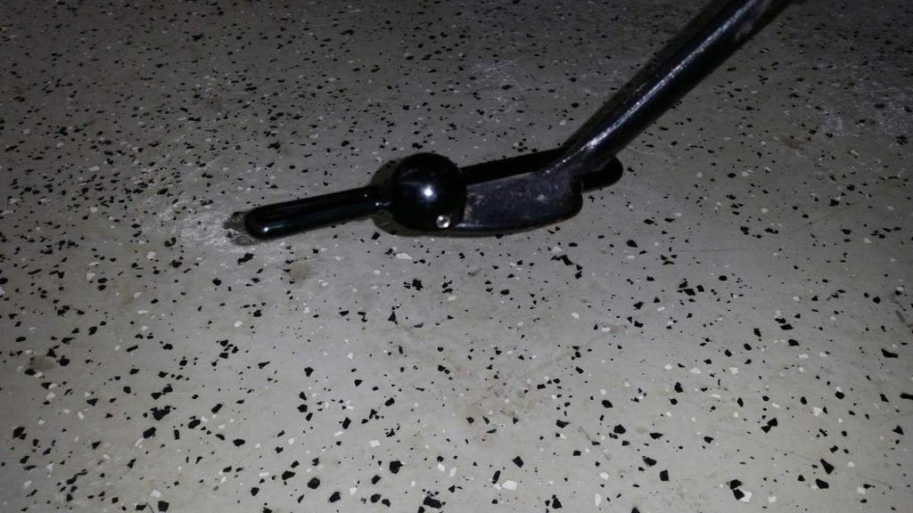
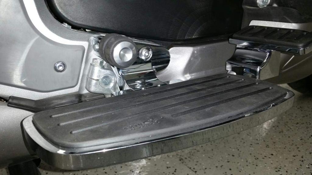
1 Honda Gold Wing GL1800 Floorboards Installation Instructions #GL Place the motorcycle on its centerstand. Remove the left and right stock foot pegs and mounts (four Allen screws, 6mm wrench size). 2. Beginning on the left or shift side - remove the rubber cover from the shift pedal. (Some WD-40 or Armor All will make it much easier). Using a hacksaw, cut the retaining knob off the end of the shift pedal as shown in Photo #1A. Don t worry - should you ever remove the floorboards, you can replace the rubber and glue it in place. 3. Install the left floorboard assembly, making sure the fork in the heel-toe shifter goes over the shift pedal. Install the two original bolts. Next - rock or pivot the floorboard assembly up and down, noting the play between the bolts and bolt holes. Position the floorboard halfway between these two extremes - then tighten the mounting bolts securely. 4. Locate the supplied black plastic shift bushing (see photo #2A). Notice the set screw on the side of the bushing - and slide the bushing onto the shift pedal with the small diameter going on first, and engaging the fork on the toe-heel shifter. The shoulder of the bushing should be touching but not putting a side force on the fork. Rotate the bushing so that the set screw is at 9 o clock, and tighten the set screw. Locate the rubber cap provided and install it over the end of the stock shift pedal. (See photo #2B). Rotate the rear wheel back and forth while shifting both up and down, then back to neutral to be sure the heel toe shifter operates smoothly. 5. Install the kickstand extension as shown in photo (3). Loosen the set screw (3A) so that it is not coming through the inside hole of the extension. Hook the J shaped loop around the back of the kickstand, and then the round cap over the ball at the tip of the stand - making sure the cap is all the way down over the kickstand ball (if the cap does not go down completely due to differences in the kickstand casting sizes, it may be necessary to file the sharp point off from the inside of the cap). Then tighten the set screw on the side of the cap securely. Peel the backing and place the supplied ¾ square clear bumper under the floorboard where the kickstand extension will contact the bottom of the floorboard when the stand is retracted and press in place firmly. 6. On the right side, referring to photo (4A) remove the 12mm brake pedal mounting bolt, noting that the punch mark on the pedal shaft aligns with the slot in the pedal. The pedal MUST be re-installed in the same position. Pull the pedal outward and off the shaft. If the pedal does not slide off the shaft easily, place a blade screwdriver into the slot, tap it in lightly to spread the slot open - then slide off (if the screwdriver is needed to remove, use this same technique when replacing the pedal). 7. Referring to diagram (5) locate the 3 rd groove from the outside and 3 rd groove from the rear on the pedal s upper serrated surface. Drill a ¼ hole thru the pedal at the intersection of these grooves. Place the brake pedal extension on top of the serrated
2 surface and check that the drilled hole lines up with the threaded hole in the bottom of the extension. 8. Locate the supplied ¼ x 7/8 bolt and ¼ lock washer. Place a drop of Loc-Tite or similar thread locking compound on the bolt s threads, and then install the bolt with lock washer from the bottom up through the pedal and into the extension - and then tighten securely. Carefully align the punch mark with the slot on the pedal and re-install the brake pedal (should the shaft slide inward you will need to remove the chrome side cover and hold the shaft outward using your finger). Install the original12mm bolt and tighten securely. 9. Install the right floorboard using the original foot peg mounting bolts. As with the left side, rock the right side up and down finding the mid or center position - and then tighten the bolts securely. It is IMPORTANT that you check for clearance between the bottom rear of the extension and front edge of the floorboard - there should be a minimum of ¼ clearance here. Also, the top of the brake pedal extension should be about 1 ½ above the top of the floorboard. If there is not then you have the pedal on the shaft incorrectly. 10. Before riding - sit on the motorcycle, checking the position of the toe and heel pedals, and move the pedals to any of the alternate holes in the shifter arm if desired. Start the motorcycle, and using the clutch, shift up and down several times and apply the rear brake, checking for smooth operation and getting the feel for using a toe heel shifter as well as the brake pedal extension and heel rest (used to assist rider control when braking). When you are satisfied all is to your liking, double check all the fasteners for tightness. Helpful hints and F.A.Q.s 1. Do not use Armor All or like products on the rubber pads, as it can make them extremely slippery. 2. The floorboards will fold up and have detents to hold them in the up position for easier maneuvering when stopped. 3. The heel rest on the right side is designed to be folded down when in traffic in order to have better access and faster reaction time to the brake pedal and be able to fold up out of the way for open highway riding. 4. The kickstand extension is designed to be used with the stock kickstand. The use of large foot kickstands or the RIVCO kickstand pad with the floorboards will easily cause them to drag when cornering. 5. The floorboards are at the same height as the stock pegs and will drag during aggressive riding. While dragging the floorboards will not affect their integrity, it will grind off some chrome and aluminum from their outer bottom edge and is not a warrantable condition. 6. Sticky shifting or when the shifter does not return to neutral position: This is caused by a slight chrome plating build-up on the inside of the shifting fork. Notice that the black plastic shifter bushing which the fork rides on makes contact with the fork at 6 & 12 o clock. (top and bottom) Remove the bushing, and using a file or sandpaper, remove a small amount of material from the bushing at the


3 contact points. Only a very small amount is all that needs to be removed. Reinstall the bushing and check the shifter s operations. RIVCO Products, Inc., 440 S. Pine Street, Burlington, WI rivcoproducts.com To register your warranty, and see many other bagger and cruiser accessories, please visit our website. A #1

4 A B #2 A #3
5 A #4 #5
Installation Instructions for FC2 & FC15 Forward Controls for the Super Magna
 Installation Instructions for FC2 & FC15 Forward Controls for the Super Magna It is highly recommended that you use a thread lock compound such as Loctite brand on all threads to keep them from vibrating
TOOL LIST FOR TAILGATE HIDDEN LATCH & LINK ASSY FOR FORD FLARESIDE TRUCKS
 TOOL LIST FOR TAILGATE HIDDEN LATCH & LINK ASSY FOR 53-87 FORD FLARESIDE TRUCKS Vise Grip Clamps C-clamps Sharpie Marker Ball Peen Hammer Center Punch 3/8 or 1/2 Drill 5/32, 7/32, 9/32, and 3/8 Drill Bits
It is highly recommended that you use a thread lock compound such as Loctite brand on all threads to keep them from vibrating loose.
 Installation instructions for FC12 Forward Controls for Kawasaki Vulcan 750 It is highly recommended that you use a thread lock compound such as Loctite brand on all threads to keep them from vibrating
Installation instructions for FC17 Forward Controls for Triumph Rocket III Roadster
 Installation instructions for FC17 Forward Controls for Triumph Rocket III Roadster It is highly recommended that you use a thread lock compound such as Loctite brand on all threads to keep them from vibrating
Tools: Sharpie, Square, Vise, Hack saw, Ruler, Punch, Hammer, File. 2. Cut the stock Place stock in vise and cut with hack saw
 Purpose: MAKE CATAPULT ARM Step 1 Tools: Sharpie, Square, Vise, Hack saw, Ruler, Punch, Hammer, File Materials: Flat aluminum ½ inch stock (see picture below) Gloves required 1. Pick up the aluminum ½
Installation instructions for FC14S Forward Controls for Shadow ACE and Aero 1100
 Installation instructions for FC14S Forward Controls for Shadow ACE and Aero 1100 It is highly recommended that you use a thread lock compound such as Loctite brand on all threads to keep them from vibrating
TRAILMATE METEOR ASSEMBLY MANUAL
 TRAILMATE METEOR ASSEMBLY MANUAL The Trailmate Meteor recumbent has been designed for easy assembly. This means more time to enjoy the smooth ride with single speed, 3 speed coaster brake and 21 speed
Nancy s Knit Knacks LLC 4 Yard Option Upgrade Kit Assembly Instructions and User Manual
 Nancy s Knit Knacks LLC 4 Yard Option Upgrade Kit Assembly Instructions and User Manual Thank you for purchasing our 4 Yard Option (4YO) Upgrade Kit. To install this upgrade you are simply going to assemble
M14 MODULAR CHASSIS SYSTEM (MOD 1) INSTRUCTION MANUAL. West Springfield, MA Phone: (866) FAX: (413)
 INSTRUCTION MANUAL. West Springfield, MA Phone: (866) FAX: (413)") M14 MODULAR CHASSIS SYSTEM (MOD 1) INSTRUCTION MANUAL Troy Industries, Inc. WWW.TROYIND.COM West Springfield, MA 01089 Phone: (866) 788-6412 FAX: (413) 383-0339 Thank You M14/M1A MODULAR CHASSIS SYSTEM
M14 MODULAR CHASSIS SYSTEM (MOD 1) INSTRUCTION MANUAL Troy Industries, Inc. WWW.TROYIND.COM West Springfield, MA 01089 Phone: (866) 788-6412 FAX: (413) 383-0339 Thank You M14/M1A MODULAR CHASSIS SYSTEM
General Features. Low Profile. The SMART BOXX stands only 1.5 off of the bed of your truck so cargo space is maximized
 General Features Low Profile. The SMART BOXX stands only 1.5 off of the bed of your truck so cargo space is maximized Two Sizes Short Box :74 L X 47 W X 7 T and Long Box 92 L X 47 W X 7 T All Aluminium
RACER TECH COMMANDER HD TIE ROD INSTALLATION
 RACER TECH COMMANDER HD TIE ROD INSTALLATION NOTE: These instructions are a universal explanation of how to install our HD Tie Rods. All kits are identical for all inner joints and nearly identical for
Installation instructions for FC9 & FC18 Forward Controls for Yamaha V-Max
 Installation instructions for FC9 & FC18 Forward Controls for 1985-2007 Yamaha V-Max It is highly recommended that you use a thread lock compound such as Loctite brand on all threads to keep them from
MINI-LATHE QUICK CHANGE TOOL POST
 MINI-LATHE QUICK CHANGE TOOL POST Cutting and assembly details Machinists should familiarize themselves with the contents of this section before jumping in to the drawings. Many details are described here
BABY WOLF LOOM. Assembly Instructions for Knocked-Down Looms
 BABY WOLF LOOM Assembly Instructions for Knocked-Down Looms BEFORE YOU BEGIN Please read through the directions before beginning to assemble your loom. Unpack the loom parts carefully. Do not throw away
WOLF PUP LOOM TM & WOLF PUP LT LOOM TM
 WOLF PUP LOOM TM & WOLF PUP LT LOOM TM Assembly Instructions FL3000 FL3006 FL3009 WOLF PUP WOLF PUP LT Find out more at schachtspindle.com Schacht Spindle Company 6101 Ben Place Boulder, CO 80301 p. 303.442.3212
-- Gym Glide -- (Recreational Game Standard) Installation Instructions
 Installation Instructions") -- Gym Glide -- (Recreational Game Standard) Installation Instructions Call Jaypro Sports Equipment at 1-800-243-0533 during regular business hours for technical support. www.jaypro.com Rev- Page 1 of
-- Gym Glide -- (Recreational Game Standard) Installation Instructions Call Jaypro Sports Equipment at 1-800-243-0533 during regular business hours for technical support. www.jaypro.com Rev- Page 1 of
00108/00110 INSTRUCTION MANUAL
 00108/00110 INSTRUCTION MANUAL Removable and Adjustable Mudflap System IMPORTANT! Exhaust Systems Note: Any modifications to the factory installed exhaust system may void your manufacturer s warranty.
Removing and Replacing the Y-truck
 Service Documentation Removing and Replacing the Y-truck To remove and replace the Y-truck you will need the following tools: 4mm Allen wrench 12mm stamped flat wrench #2 Phillips screwdriver (magnetic
INSTALLATION INSTRUCTIONS GRILLE GUARD 09-ON DODGE RAM PART #
 INSTALLATION INSTRUCTIONS GRILLE GUARD 09-ON DODGE RAM PART # PARTS LIST: Qty Description Qty Description 1 Grille Guard 8 12-1.75mm x 35mm Hex Bolts 2 Brackets (for trucks without 22 12mm x 30.1mm OD
INSTALLATION INSTRUCTIONS CHEVY C-10 INDEPENDENT FRONT SUSPENSION
 INSTALLATION INSTRUCTIONS 73-87 CHEVY C-10 INDEPENDENT FRONT SUSPENSION Please read these instructions completely before starting your installation. Assemble suspension on vehicle before powder-coating
CV1B Sliding Table Installation and Setup Guide
 CV1B Sliding Table Installation and Setup Guide Tech Mark, Inc 7901 Industry Drive North Little Rock, AR 72117 tel (501) 945-9393 fax (501) 945-0312 www.tech-mark.com email: info@tech-mark.com The CV1B
SINCE 1922 P UBLICATION N O
 SINCE 1922 GARED SPORTS MICRO-Z SET-UP INSTRUCTIONS VERY IMPORTANT! READ INSTRUCTIONS CAREFULLY AND FOLLOW STEP BY STEP SET-UP PROCEDURE P UBLICATION N O. 5 5 1 7 5 2 9 1 6 Recommended tools and accessories.
Oasis Recliner Disassembly Instructions
 These instructions may be used to disassemble all versions of our Oasis Recliner seating line and available options. Time Required: 20 minutes. (Internal metal frame) D: Reaching up and inside the back,
Replacing the Reciprocator on an SWF Multi-head.
 Replacing the Reciprocator on an SWF Multi-head. Follow the instructions below to replace the reciprocator in the SWF multi-head machines. The tools required are found in the tool kit that came with the
MAG-CONV Basic, 48, 48R & Midline Front Mount
 Parts Required: Tools Used: Mag Wheels Brakes Brake Rods Mounting Bracket Anti Tippers 7/16" Wrench Screw Driver Rubber Mallet 5/8 Wrench 5mm Allen Wrench Step Execution Figures 1 Remove front 5" total
FBX1104P FBX1104 FBX1106P FBX1106
 FBX1104P FBX1104 FBX1106P FBX1106 Second edition : September 2004 No. 040037 INTRODUCTION Thank you for your purchasing Kansai Special's FBX Series. Read and study this instruction manual carefully before
mila-wall (Series100) General Operating Instructions page 1 of 15
 General Operating Instructions page 1 of 15") mila-wall (Series100) General Operating Instructions page 1 of 15 Step #1: Before setting up walls, lower adjustable leveling feet on each panel approximately 1". This will allow access to the threaded
mila-wall (Series100) General Operating Instructions page 1 of 15 Step #1: Before setting up walls, lower adjustable leveling feet on each panel approximately 1". This will allow access to the threaded
Medium HoneyBadger Chase Rack Installation Instructions
 PREPARATION Medium HoneyBadger Chase Rack Installation Instructions 1. Disconnect the negative terminal on the battery. Park the vehicle on level ground and set the emergency brake. 2. We recommend reading
CONTROLS KIT FOR ALL # & # HARLEY DAVIDSON SPORTSTER MODELS
 INSTALLATION INSTRUCTIONS TC BROS. CHOPPERS PART #0-0075 & #0-0076 (No Pegs) FORWARD CONTROLS KIT FOR ALL 00-0 HARLEY DAVIDSON SPORTSTER MODELS If downloading & printing these instructions online, be sure
INSTALLATION INSTRUCTIONS DODGE RAM 2 & 4WD 1500 PART # P5058
 INSTALLATION INSTRUCTIONS 2009-13 DODGE RAM 2 & 4WD 1500 PART # P5058 PARTS LIST: Qty Description Qty Description 1 Grille Guard 12 12-1.75mm Hex Nuts 2 Upper Frame Mounting s (for trucks without tow hooks
Elimination of Elevator Bounce
 For the Agilent Archon Autosampler Rework Instructions CAUTION This kit is intended for use by Agilent Service personnel only. Elevator Removal 1 Open top cover. 2 Open front lower door. 3 Remove vial
Astro-Physics Inc. 400QMD Lubrication/Maintenance Guide
 Astro-Physics Inc. 400QMD Lubrication/Maintenance Guide The following guidelines should be followed to lubricate the three main parts of the 400QMD mount. The QMD stands for Quartz Micro-Drive controller.
LifeGear G1 /HOME GYM ITEM NO.: 63100
 LifeGear G1 /HOME GYM ITEM NO.: 63100 OWNER S MANUAL IMPORTANT: Read all instructions carefully before using this product. Retain this owner s manual for future reference. The specifications of this product
STRINGING MACHINE OWNER'S MANUAL. Copyright 1998 GAMMA Sports - All Rights Reserved
 6002 STRINGING MACHINE OWNER'S MANUAL Issue 3 - June 20, 1998 Copyright 1998 GAMMA Sports - All Rights Reserved 6002 OWNER'S MANUAL TABLE OF CONTENTS PAGE 1... WARRANTY PAGE 2... FEATURES PAGE 3... ASSEMBLY
LU6X-130 Instructions and Parts List (including LU6X Basic) Operating Instructions
 Operating Instructions") LORTONE LU6X-130 Item # 061-092 LU6X Basic Item # 061-090 LU6X-130 Instructions and Parts List (including LU6X Basic) Operating Instructions Introduction The LU6X is one the most versatile pieces of equipment
LORTONE LU6X-130 Item # 061-092 LU6X Basic Item # 061-090 LU6X-130 Instructions and Parts List (including LU6X Basic) Operating Instructions Introduction The LU6X is one the most versatile pieces of equipment
EDGE2 DUAL MONITOR ARM
 EDGE2 DUAL MONITOR ARM EDGE2 Rev A 2/17 Model EDGE2-SLV Model EDGE2-BLK Model EDGE2-WHT ASSEMBLY AND ADJUSTMENT EDGE2 DUAL MONITOR ARM PARTS AND TOOLS PLEASE REVIEW these instructions before beginning
Installation Instructions
 by Plato Woodwork Installation Instructions Plato Woodwork, Inc. 200 Third Street SW P.O. Box 98 Plato, MN 55370 www.platowoodwork.com 800.328.5924 SECTION GUIDE GETTING STARTED PAGE # Installation Methods...
INSTALLATION INSTRUCTIONS GRILLE GUARD RAM 1500 PART # 5058/5058-2
 INSTALLATION INSTRUCTIONS GRILLE GUARD PART # 5058/5058-2 PARTS LIST: Qty Description Qty Description 1 Grille Guard 8 12-1.75mm x 35mm Hex Bolts 2 Upper Frame Mounting s (for trucks without tow hooks
PHG-1000X. Owner s Manual HOME GYM
 HOME GYM Owner s Manual WWW.BODYSOLID.COM THERE IS A RISK ASSUMED BY INDIVIDUALS WHO USE THIS TYPE OF EQUIPMENT. TO MINIMIZE RISK, YOU MUST FOLLOW THESE RULES:! " # $ % & ' ( ) * + ' (, ' " -. *, * ) )
Depending on the size you ordered you will have either 5 Foot sections which will build the 10 Foot frame or 6 Foot sections which will build the 12
 XL Quilting Frame 1 Depending on the size you ordered you will have either 5 Foot sections which will build the 10 Foot frame or 6 Foot sections which will build the 12 Foot frame Printed 2 June 2014 Updated
USSC LLC 4 ONE LLC FIELD MODIFICATION INSTRUCTIONS
 1 OF 17 A 1. PURPOSE: Instructions for in field replacement of 9004 mechanical suspension top pan 2. SCOPE: 9004 mechanical suspension with legacy two point LX back frame and current LX back frame 3. PROCEDURE:
Giraud Tool Company, Inc.
 Motor Upgrade for Gracey Trimmer This package is intended to allow the user to upgrade their Gracey trimmer with a higher rpm motor and convenience features not found in the production offering. This upgrade
P.O. Box 8400 Green Bay, WI (920)
") P.O. Box 8400 Green Bay, WI 54308-8400 (920) 468-2165 Change Notice No. 112 Implemented By: KI-Pembroke Notification By: Scott Vissers Date: 03/15/10 Component Product Title: Series XXI Lateral Filing
P.O. Box 8400 Green Bay, WI 54308-8400 (920) 468-2165 Change Notice No. 112 Implemented By: KI-Pembroke Notification By: Scott Vissers Date: 03/15/10 Component Product Title: Series XXI Lateral Filing
Electric Skein Winder
 Electric Skein Winder Assembly and Use Package Contents 1 - Triangular Body (w/ motor) 1 - Cross Arm 1 - Left Foot (w/ yarn guide) 1 - Right Foot 1 - Adjustable Finger (w/ yarn clip) 3 - Adjustable Fingers
Chain Drive Vise. Installation Instructions. (revised 11/29/2018)
") Chain Drive Vise Installation Instructions (revised 11/29/2018) Lie-Nielsen Chain Drive Vise Instructions Table of Contents page About Your Chain Drive Vise 3 Parts List 4 Exploded Parts Diagram 5 step
Chain Drive Vise Installation Instructions (revised 11/29/2018) Lie-Nielsen Chain Drive Vise Instructions Table of Contents page About Your Chain Drive Vise 3 Parts List 4 Exploded Parts Diagram 5 step
Continuum Frame Assembly Instructions
 Continuum Frame Assembly Instructions Copyright January 1, 2017 Jim M. Bagley, GraceWood, Inc (Reproduction Prohibited) Version 2.2 Table of Contents Continuum Frame Table of Contents... i Warranty...ii
GlideRite Retractable Cover System For Hot Spot Spas (SE & SLX only)
") List of Contents Quantity Description 12 #10 x 1 ½ Flat Head Phillips Screw (see pg. 2) 2 #10 x ½ Pan Head Phillips Screw (see pg. 2) 8 ¼ x 2 ½ Lag Bolt (see pg. 2) 7 ¼ 20 x 5 / 8 Hex Head Bolt (see pg.
List of Contents Quantity Description 12 #10 x 1 ½ Flat Head Phillips Screw (see pg. 2) 2 #10 x ½ Pan Head Phillips Screw (see pg. 2) 8 ¼ x 2 ½ Lag Bolt (see pg. 2) 7 ¼ 20 x 5 / 8 Hex Head Bolt (see pg.
Chain Drive Vise. Installation Instructions. (revised 05/04/2016)
") Chain Drive Vise Installation Instructions (revised 05/04/2016) Lie-Nielsen Chain Drive Vise Instructions Table of Contents page About Your Chain Drive Vise 3 Parts List 4 Exploded Parts Diagram 5 step
Chain Drive Vise Installation Instructions (revised 05/04/2016) Lie-Nielsen Chain Drive Vise Instructions Table of Contents page About Your Chain Drive Vise 3 Parts List 4 Exploded Parts Diagram 5 step
AUTOMATIC ADVANCE MANUAL
 AUTOMATIC ADVANCE MANUAL AVL Looms, Inc. 3851 Morrow Lane, Suite #9 Chico, CA 95928-8305 530 893-4915 530 893-1372 fax # info@avlusa.com www.avlusa.com Copyright 2009 TABLE OF CONTENTS Page # I. Parts.........................
Model 209 Fireback Replacement
 Model 209 Fireback Replacement Please read all the instructions before you begin the procedure. Confirm that you have all the necessary tools and materials. If you have any questions, technical support
OWNER S MANUAL. Safety. Please read this owner s manual before use and keep it at hand for reference. Warranty
 Please read this owner s manual before use and keep it at hand for reference. OWNER S MANUAL Safety Important safety instructions for using the INCRA Miter5000 Before using the INCRA Miter5000, read and
Polaris General 1000 EPS 2016
 Contact Us: FACTORY UTV LLC. 9237 Beatty Drive Sacramento, CA 95826 Phone : (916) 383-2730 E-mail : info@factoryutv.net Go online: www.factoryutv.net U.H.M.W. Skid Plate / Under Armor Package Ultra. High.
Service Manual. 600 Series Box Frame Steering Shaft and Segment Gear Servicing
 Service Manual 600 Series Box Frame (These procedures are appropriate for box frame tractors produced after November 2002) IMPORTANT: READ SAFETY RULES AND INSTRUCTIONS CAREFULLY This Service Manual is
SAFETY INSTRUCTIONS. Wear protective clothing, including safety glasses and steel toe boots.
 SAFETY INSTRUCTIONS Wear protective clothing, including safety glasses and steel toe boots. DO NOT allow loose clothing or long hair near machine operations. Keep work site and machine clean. Use brush
Your new. Rose. spinning wheel. majacraft. all you need to spin your dreams... majacraft
 Your new Rose spinning wheel all you need to spin your dreams... 1 Welcome to the Majacraft family Congratulations on purchasing a new Majacraft Rose. We are very proud of this wheel and hope that it allows
INSTALLATION GUIDE 2009-CURRENT HUMMER H3T PRODUCT CODE:
 INSTALLATION GUIDE 2009-CURRENT HUMMER H3T PRODUCT CODE: 268 June 22, 2010 TOOLS NEEDED COMPONENTS INCLUDED P2 Tip 3/8" Drill Rubber Gasket(s) x 2 Bracket(s) x 2 1/2" Drill Bit Bulkhead Flange #2 Phillips
Assembly Instructions 10 X 10 Aluminum Roof Support
 Assembly Instructions 10 X 10 Aluminum Roof Support Aluminum Roof Support Bolt Package 16-5/16 X 2 ¼ SS Bolt 24-5/16 X 1 SS Bolt 40-5/16 SS Nylon Lock Nuts 16-5/16 SS Flat Washers 28-4 ½ Wood Screws 36-1
WPS crew Doors Installation instructions
 WPS-132-133 crew Doors Installation instructions ORDER OF INSTALLATION FOR A COMPLETE ENCLOSURE OF A CREW WPS (Weather Protection System) IS AS FOLLOWS: 1. Heater 2. Rear Thresholds - Right Hand & Left
Side Winder R o u t e r L i f t.
 Woodpeckers PRECISION WOODWORKING TOOLS Side Winder R o u t e r L i f t. INSTALLATION INSTRUCTIONS The wrench handle must be pointing left in order to fully insert or remove it. Lift Wrench Once fully
Interactive Monitor Arm
 Interactive Monitor Arm Tools Required -5mm Allen wrench -Phillips screwdriver -Plastic mallet There are two ways to attach a Monitor Arm to a Full Frame; with a Beam, or with a Post Mount. Both methods
6625 WEST WILSHIRE BLVD. OKLAHOMA CITY, OK (405) FAX (405)
 FAX (405)") INSTALLATION INSTRUCTIONS FOR THE TAILGATE WITH LATCH AND LINK ASSEMBLY 76-87 FORD SHORT & 53-87 FORD LONG FLARESIDES 1. Assemble the bed and make sure the box is square. Measure the distance between the
INSTALLATION INSTRUCTIONS FOR THE TAILGATE WITH LATCH AND LINK ASSEMBLY 76-87 FORD SHORT & 53-87 FORD LONG FLARESIDES 1. Assemble the bed and make sure the box is square. Measure the distance between the
REPAIR INSTRUCTIONS: CABLE
 The repair instructions describe replacing the Cable in the Easy Sun PARASOL Sunshade. These repair instructions are intended only for persons with experience of using the tools required. Please read the
RRevo. Written By: Bradley Hanstad TOOLS: PARTS:
 RRevo RRevo Robot Kit Version 2 Complete build and setup guide for the RRevo Robot Kit. From 15 pound combat to robot hockey, this kit is designed to be the perfect starting platform to get in the competition
IMPORTANT: WILL NOT FIT COUNTRYMAN MODELS
 Part #1410-0102-07 2 3 1 IMPORTANT: WILL NOT FIT COUNTRYMAN MODELS Apply masking tape around the bottom grille opening and across the bottom of the upper facto ry grille.. Open the hood and remove the
SIDE FOLDING POST ADJUSTMENTS
 SIDE FOLDING POST ADJUSTMENTS TABLE OF CONTENTS WARNINGS AND SAFETY INFORMATION 3 TOOLS REQUIRED 4 GENERAL NOTES 5 POST IDENTIFICATION 6 POST TO CURTAIN CONNECTIONS 8 P01/P03 LOCK PLATE HEIGHT ADJUSTMENT
Basic steps to time the Gammill quilting machine s rotary sewing hook
 Basic steps to time the Gammill quilting machine s rotary sewing hook 1.) Turn the machine off and unplug it. 2.) With the needle bar in the raised position, remove the bobbin and bobbin case. 3.) Remove
The Bowflex Revolution XP Home Gym Assembly Instructions. P/N: Rev ( /0 )
") P/N: 001-7057 Rev ( /0 ) The Bowflex Revolution XP Home Gym Assembly Instructions 2 Table of Contents Before You Start... 2 Tools You Will Need / Hardware Contents... 3 Box Contents... 6 Assembling Your
P/N: 001-7057 Rev ( /0 ) The Bowflex Revolution XP Home Gym Assembly Instructions 2 Table of Contents Before You Start... 2 Tools You Will Need / Hardware Contents... 3 Box Contents... 6 Assembling Your
ASSEMBLY AND ADJUSTMENT
 EDGE MONITOR ARM EDGE Rev A 2/17 Model EDGE-SLV Model EDGE-BLK Model EDGE-WHT ASSEMBLY AND ADJUSTMENT EDGE MONITOR ARM PARTS AND TOOLS PLEASE REVIEW these instructions before beginning the assembly and
TOOLS REQUIRED Metal Wood Wood and Metal Screws. #16 Drill #12-24 Tap. 1/8 Drill
 DEVICES COVERED IN THIS DOCUMENT: 4700S Surface Vertical Rod Device 4700SF Fire Exit Surface Vertical Rod Device TOOLS REQUIRED Metal Wood Wood and Metal Screws Sex Bolts #7 Drill ¼ -20 Tap #16 Drill #12-24
MobileTrak5 Installation Instructions
 MobileTrak5 Installation Instructions PLEASE OPEN ALL BOXES & CHECK TO MAKE SURE YOU HAVE ALL PIECES REQUIRED READ ALL INSTRUCTIONS BEFORE STARTING Tools Required for Assembly 7/16, 1/2 Wrench Phillips
TITAN2-EDGE Public Access Computer Station Dual Track
 TITAN2-EDGE Public Access Computer Station Dual Track TITAN2-EDGE Rev A 6/17 Model TITAN2-EDGE ASSEMBLY AND ADJUSTMENT TITAN2-EDGE PARTS AND TOOLS PLEASE REVIEW these instructions before beginning the
OWNER S MANUAL CONTENTS. The only table saw fence with Automatic Positioning Control TM
 The only table saw fence with Automatic Positioning Control TM OWNER S MANUAL Please read this owner s manual before use and keep it at hand for reference. Note: The INCRA TS II system consists of three
Installation Guide for Rough Country 1.25 inch Body Lift Kit w/o Shocks (07-15 Wrangler JK 4 Door) Item # J10048 Option B; Manual
 Item # J10048 Option B; Manual") Installation Guide for Rough Country 1.25 inch Body Lift Kit w/o Shocks (07-15 Wrangler JK 4 Door) Item # J10048 Option B; Manual Installation Time: 3 Hours Tools Required: Jack (Tall enough to reach body
Installation Guide for Rough Country 1.25 inch Body Lift Kit w/o Shocks (07-15 Wrangler JK 4 Door) Item # J10048 Option B; Manual Installation Time: 3 Hours Tools Required: Jack (Tall enough to reach body
O-Sullivan King 4 Poster Bed O-Sullivan Queen 4 Poster Bed Parts and Hardware List
 Parts and Hardware List A. Left Headboard Post 1 pc B. Right Headboard Post 1 pc C. Left Footboard Post 1 pc D. Right Footboard Post 1 pc E. Headboard Panel 1 pc F. Footboard Rail 1 pc. Spindles 4 pcs
Rim-Lock Door Set Installation Instructions
 Rim-Lock Door Set Installation Instructions Let s get started Check Your Parts List Two Doorknobs with Set Screws B. Doorknob Spindle C. Rim Lock with Mounting Screws D. Keeper with Mounting Screws E.
EPPA2-KIT DUAL MONITOR ARM CONVERSION
 EPPA2-KIT DUAL MONITOR ARM CONVERSION EPPA2-KIT Rev A 10/17 Model EPPA2-KIT-XXX ASSEMBLY AND ADJUSTMENT EPPA2-KIT PARTS AND TOOLS PLEASE REVIEW these instructions before beginning the assembly and adjustment
model tsa-sa48 Sliding Crosscut Table installation guide
 model tsa-sa48 Sliding Crosscut Table installation guide A Note About Color Variations Among Anodized Aluminum Components Congratulations on the purchase of this SawStop Sliding Crosscut Table. We at SawStop
Dream Fabric Frame Assembly Instructions
 Dream Fabric Frame Assembly Instructions Copyright May 01, 2015 Jim M. Bagley, GraceWood, Inc (Reproduction Prohibited) Version 1 Table Of Contents Parts List 3 Step 1: Table Set Up 6 Step 2: Install the
Assembly Instructions
 InTandem Table System November 20 InTandem Table System - Worksurface #4 x/" 4 wood screw power beam Tools Provided T-0 Extended Torx Driver T-25 Torx Driver Additional Tools Required Soft protective
Warnings. Description. Prior to Installation Tools Needed
 Warnings Failure to act in accordance with the following may result in death or personal injury. The JT Strong Arm Stabilizer System is intended to eliminate chassis movement in travel trailers and fifth
INSTALLATION OF WELLS SUPER QUICK CHUCK LEFT HAND ON RED WING LATHE
 DENTAL, INC. TECHNICAL BULLETIN Q824-022510 5860 FLYNN CREEK ROAD READ ALL INSTRUCTIONS P.O. BOX 106 BEFORE PROCEEDING COMPTCHE, CALIFORNIA, U.S.A. 95427 SAVE THIS FOR FUTURE REFERENCE www.wellsdental.com
OPERATIONS MANUAL. Port-O-Slitter
 Tapco Products Company The World Leader in Specialty Tools for the Professional Port-O-Slitter OPERATIONS MANUAL General instructions, set up, accessories and guide to using your portable precision slitting,
Thorvie Instructions Always wear eye protection and do not wear loose clothing when operating machinery. FOR AV- 41 ICE AUGER MACHINE
 FOR AV- 41 ICE AUGER MACHINE 1. Please study video and all instructions before proceeding to grind. For Mora, Jeffy and Eskimo blades use the 6 brown resin bond wheel. Mount with washer and left-hand nut
FlexFrame - Storage Components and Skins
 FlexFrame - Storage Components and Skins 1/4 Square Drive Ball-Point Hex-Bit Socket 1/8 Short Hex, 1-1/2 Overall Length McMaster Part # 54075A44 Table of Contents Topic Page Storage Components 2 General
Customer Notice: Congratulations again on your SawStop purchase, and thank you! -SawStop Tualatin, OR
 Customer Notice: Congratulations on the purchase of this Sliding Crosscut Attachment. As the owner of a SawStop saw, you are familiar with our high standards for quality, fit and finish. Different from
Safety Instructions, Installation & Operator's Manual For. # CLAMSHELL GRASS CA TCHER KIT For 28" & 33" REAR ENGINE RIDING MOWERS
 Safety Instructions, Installation & Operator's Manual For #6-3125 CLAMSHELL GRASS CA TCHER KIT For 28" & 33" REAR ENGINE RIDING MOWERS 28" REAR ENGINE RIDER WITH CLAMSHELL BAGGER KIT SHOWN SNAPPER, McDonough,
BildaBike Assembly. Cruiser: *Disclaimer*
 BildaBike Assembly *Disclaimer* While we do provide basic tools for assembly, we highly recommend visiting your local bike shop to have a professional bike mechanic build or inspect your new bike. There
Find out more at schachtspindle.com Schacht Spindle Company 6101 Ben Place Boulder, CO p f
 WOLF STROLLER FL3051 Assembly Instructions folded ready to travel open ready to weave For installation on Wolf Pup, Wolf Pup LT, Baby Wolf, and Mighty Wolf Looms Find out more at schachtspindle.com Schacht
Click Here to Go Back
 Click Here to Go Back Fig. -94 Fig. -97 CC42D 10. Remove the cap screw securing the gear shift stopper plate pin retainer; then remove the retainer. Fig. -95 CC45D 12. Remove the link arm and account for
GlideRite Retractable Cover System For HotSpring & Tiger River Spas (except Classic & pre-2000 Landmark Spas)
") List of Contents Quantity Description 12 #10 x 1 ½ Flat Head Phillips Screw (see pg. 2) 2 #10 x ½ Pan Head Phillips Screw (see pg. 2) 8 ¼ x 2 ½ Lag Bolt (see pg. 2) 7 ¼ 20 x 5 / 8 Hex Head Bolt (see pg.
List of Contents Quantity Description 12 #10 x 1 ½ Flat Head Phillips Screw (see pg. 2) 2 #10 x ½ Pan Head Phillips Screw (see pg. 2) 8 ¼ x 2 ½ Lag Bolt (see pg. 2) 7 ¼ 20 x 5 / 8 Hex Head Bolt (see pg.
IDR assembly instructions:
 IDR assembly instructions: Required Tools: 2 X 12mm Open End Wrench 14mm open end wrench #2 Phillips Head Screw Driver (Drill with adjustable torque clutch recommended) 8mm nut driver (Supplied in IDR-AK)
EmagiKit. Privacy Pod Plus. Quiet. Easy. Affordable. INSTRUCTIONS ASSEMBLY
 EmagiKit Privacy Pod Plus Quiet. Easy. Affordable. INSTRUCTIONS ASSEMBLY DIMENSIONS AND COMPONENTS 47 47 Ceiling Unit 2-B 2-L 2-R Glass Door Corner Trim Door Handle 90 Adjustable Height Work Surface 1-B
LINEAR BEARING SMITH MACHINE. Assembly Manual (888) FOR YOUR SAFETY READ ALL INSTRUCTIONS CAREFULLY
 FOR YOUR SAFETY READ ALL INSTRUCTIONS CAREFULLY") DF4900 LINEAR BEARING SMITH MACHINE Assembly Manual (888) 258-0533 FOR YOUR SAFETY READ ALL INSTRUCTIONS CAREFULLY *NOTE IF YOU ARE MISSING HARDWARE OR HAVE ANY FIT UP PROBLEMS PLEASE CONTACT DELTECH FITNESS
DF4900 LINEAR BEARING SMITH MACHINE Assembly Manual (888) 258-0533 FOR YOUR SAFETY READ ALL INSTRUCTIONS CAREFULLY *NOTE IF YOU ARE MISSING HARDWARE OR HAVE ANY FIT UP PROBLEMS PLEASE CONTACT DELTECH FITNESS
Rugged Ridge Engine Transmission Skid Plate JK
 Installation Time: 1-2 Hours Tools Required: Rugged Ridge Engine Transmission Skid Plate 2012-2017 JK Sockets: 16mm, 17mm, 18mm deep well Socket Wrench Wrenches: 16mm, 18mm Torque Wrench Drill ½ Drill
DeRosa DRM-516 (5-PIECE 16 ) Drum Kit ASSEMBLY INSTRUCTIONS
 Drum Kit ASSEMBLY INSTRUCTIONS") DeRosa DRM-516 (5-PIECE 16 ) Drum Kit ASSEMBLY INSTRUCTIONS Along with reading this guide, we also recommend that you watch the DeRosa 516 Drum Kit Assembly video on the Austin Bazaar Product FAQ page
DeRosa DRM-516 (5-PIECE 16 ) Drum Kit ASSEMBLY INSTRUCTIONS Along with reading this guide, we also recommend that you watch the DeRosa 516 Drum Kit Assembly video on the Austin Bazaar Product FAQ page
Introduction. Rocky Mountain Westy Swing Away Carrier Kit Installation Instructions
 Rocky Mountain Westy Swing Away Carrier Kit Installation Instructions Introduction Thank you for purchasing the Rocky Mountain Westy Swing Away Carrier Kit. We pride ourselves in the products we develop
V-Groover SIMPLEX INSTRUCTION AND OPERATION MANUAL M O DEL 703. For best results use only authentic Logan blades.
 www.logangraphic.com SIMPLEX M O DEL 703 INSTRUCTION AND OPERATION MANUAL For best results use only authentic Logan blades CAUTION: BLADES EXTREMELY SHARP Use replacement blades #1258 Logan Graphic Products,
It is highly recommended that you use a thread lock compound such as Loctite brand on all threads to keep them from vibrating loose.
 Installation instructions for JM1 Jerry Can Mount for Toyota FJ Cruiser It is highly recommended that you use a thread lock compound such as Loctite brand on all threads to keep them from vibrating loose.
00108/00110 INSTRUCTION MANUAL
 00108/00110 INSTRUCTION MANUAL Removable and Adjustable Mudflap System IMPORTANT! Please Read this Instruction Booklet prior to assembly of your Rock Tamer Kit. IMPORTANT! Exhaust Systems Note: Any modifications