An Adjustable Threading Feed Attachment for a Lathe Without Metric Threading Capability, by Ted Clarke
|
|
|
- Bryce Sullivan
- 5 years ago
- Views:
Transcription

1 An Adjustable Threading Feed Attachment for a Lathe Without Metric Threading Capability by Ted Clarke Metric pitch threads, with the exception of the Royal Microscopical Society (RMS) 36 threads per inch Whitworth thread still common on microscope objectives, have long been standard on microscope components. I have used the metric threading patterns on my 1960s vintage Unimat lathe shown in Figure 1, but the patterns for many of the common, fine pitch ISO metric thread pitches were not available for the Unimat. An engineer acquaintance from England also has a strong interest in home shop machining capability. He gave me a copy of an article from the English Magazine Model Engineers Workshop by Ted McDuffie in the autumn 1990 issue. This article, A Variable Lead Threading Attachment, was very interesting for me, but I did not at that time own a bench lathe of conventional design that could use this attachment. Since retiring, I completed restoring a Wade 8A precision bench lathe once owned by the United States Navy. I referred back to the McDuffie article to see how I could make a similar attachment for the Wade lathe so I can cut metric threads using the closest thread pitch in the inch system of the Wade quick change gear box. My plan is to make the missing metric thread patterns for my Unimat, because the setup time will be less for metric threading with the Unimat, and its higher spindle speeds are an advantage for making small diameter screws for optical equipment. Figure 1 Henry Maudslay was the inventor of the first precision lathes in England at the start of the industrial age. Maudslay s work is described in Robert S. Woodbury, Studies in the History of Machine Tools, The MIT Press, Woodbury notes that Maudslay used a clever lever system to adjust the thread pitch when making a new lead screw. Maudslay developed precision lead screws with the desired thread pitch and minimal variation in the thread pitch. The McDuffie attachment uses a lever system perhaps inspired by Maudslay s earlier method. The Wade lathe has a taper turning attachment that I thought could be used to actuate the lead adjusting linkage instead of what McDuffie calls a variable vane clamped to a front box way of his Myford Super 7 lathe. McDuffie added a dovetail slide between the carriage cross slide and the compound. The axis of this slide is parallel to the lathe bed. This added slide is actuated by a lever system so that the tool longitudinal travel is the travel of this small slide added to or subtracted from the carriage travel provided by the threading lead screw. This added travel must be directly proportional to the amount of carriage travel if the lead of the thread being cut is to remain constant. The issue of linearity of the movement will be dealt with at the end of this article, along with a test for linearity. ModernMicroscopy.com / Microscopy in the Home Shop 1


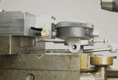
2 The lever system drive I made for the short slide is best understood from examining photographs of the attachment I made for the Wade lathe. Figure 2 shows a setup for conventional outside diameter threading without the attachment. The view is from the back side so it can be compared with Figures 3 and 4 with the adjustable lead attachment engaged by a four-bar linkage clamped to the slider of the taper attachment for outside diameter and inside diameter threading. The lever system is on the headstock side of the carriage in order to have adequate room for the tailstock to support the work being threaded. Interference of the long link with the chuck is now an issue. So the length of the short arms was minimized while still providing about 1/8 travel of the short slide when the taper attachment is set at its maximum angle of 10 degrees. The short slide adds almost an inch to the height of the compound. An offset tool holder was made to accommodate this added height and is described in more detail later. The compound and top of the short slide were removed to show the four-bar linkage in Figures 5 and 6. The long link bar was disconnected from the taper attachment slider and moved forward and backward to show how an L shaped lever, pinned with the longer dowel pin to the lower half of the slide, rotates so that the short dowel pin on the other end moves approximately longitudinally. This short pin engages with a gray cast iron slider fitting into a transverse slot in the underside of the upper half of the slide. The top half of the short slide was inverted and laid on the lower half to show the slider in the slot cut with an end mill in Figure 7. The sides of the slot and mating slider were precision fitted with a small scraper. Figure 2 Figure 3 Figure 4 Figure 5 ModernMicroscopy.com / Microscopy in the Home Shop 2


3 Figure 6 Figure 7 The top of the Wade cross slide, shown in Figure 8, has a cylindrical center post and a groove for T nuts that locate and attach the compound to the cross slide. This method of attachment differs from the Myford lathe of McDuffie, which has a rotary dovetail post clamped by transverse screws. I chose to assemble the lower half of the slide to the cross slide with bolts followed by installing the upper half of the slide with the L shaped arm with the slider engaged in the slot. Since the travel of the short slide will be a maximum of 1/8 in either direction, a long dowel pin passes through a 1/2 diameter clearance hole through the top of the slider and through the L shaped lever into the lower half of the slide. The hardened dowel pin was sized for a close push fit in the reamed holes of the lever and lower half of the slide by stoning with the pin rotating in a drill chuck. The upper part of this hardened dowel pin has a rough ground groove so it can be easily grabbed with a needle-nosed pliers for later removal. A tapered end pin is used to quickly align the hole in the lever with the hole in the lower half of the slide. The pin through the half-inch clearance hole is shown at the limits of slide travel in Figures 9 and 10. The use of a tapered gib, made from gray cast iron, permits easy assembly of the short slide. The thicker end of the gib with a mating wide screw head is visible on the upper right corner of the slide in Photos 10 and 11. A series of tapped holes is visible in the top of the slide, shown in Figure 12: these allow the compound to be mounted at a degree angle for threading. Figures 9 and 10 also show scribed lines on the bottom side of the slide for alignment with the cross slide and to indicate the amount of travel from the centered position with the shorter leg of the L lever arm square to the longitudinal axis. Figure 8 Figure 9 ModernMicroscopy.com / Microscopy in the Home Shop 3


4 Figure 10 Figure 11 The long lever was removed to show details of the slide from the headstock side in Figure 11. Note that the outer portions of the dovetail are load bearing with a close fitting slot containing the L shaped lever. The thin end of the tapered gib can be seen on the left side. The end of the gib was trimmed to be flush with the end of the top half of the slide, and located by the head of a screw. The shaper cut load bearing surfaces of the slide were hand scraped for a precision fit and fine finish. This method was also relied upon by Henry Maudslay to make precision lathes. The slide moves with slight effort and no perception of roughness. Ted McDuffie relied upon lapping to improve the finish on his milled slide surfaces. Rubbing the mating surfaces together with abrasive, unlike properly done hand scraping, will not correct the form errors. I chose to make the slide from hot rolled steel to avoid warping expected if cold rolled steel, with its locked-in residual stress gradients, had been used. I would not consider using aluminum for the slide because of the poor compatibility of aluminum rubbing on aluminum as a wear couple. The adjustable stop I had for the cross slide can not be used with the threading attachment. I find that such a stop is very desirable for threading because a dial setting does not have to be watched between threading passes when the tool is backed from the cut and returned to the same setting. A new stop was added which bolts to the lower half of the short slide as shown also in Figure 11. It is very important that the opposite links of the drive system have the same length so that the opposite links remain parallel when the end of the long link is clamped to the slider of the taper turning attachment that actuates this linkage as the carriage moves (Figure 12). The short link and the corresponding segment of the L shaped lever have a pin hole spacing of 2.250". A gauge was made to set the adjustable ends of the long lengths exactly the same. The exposed ends of the dowel pin pivots fit reamed holes in bushings clamped into the gauge bar as shown in Figures 13 and 14. Having access to the long pin in the lower half of the slide through the clearance hole in the upper half of the slide is an aid to easy use of the gauge. The thumbscrews allow the bushings to be set to allow for the different heights of the pivots, which are not on the same plane. ModernMicroscopy.com / Microscopy in the Home Shop 4


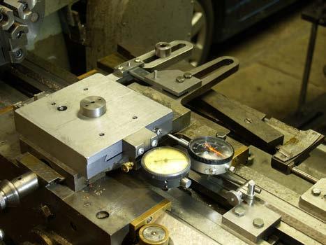
5 Figure 12 Figure 13 Figure 14 I use the Phase II tool holder system on the Wade lathe. The added height from the short slide required fabricating the offset tool holder shown in Figures 15 and 16. It was made from 1.25" thick hot rolled steel. The tool holder clears the top of the male dovetail of the Wade compound. So the full travel of the compound is available to suit the diameter being threaded. Ted McDuffie also had to make a special offset tool holder for use with his attachment for the Myford lathe. Figure 17 shows the lathe from the front side set for internal threading with the new attachment and tool holder. The two dial indicators are for calibration of the thread lead adjustment provided by the short slide. The dial indicator at the rear measures the carriage movement; it is not normally needed, but is shown because it was used to check the linearity of the threading lead adjustment provided by the threading attachment. A 1" gauge block was used to verify that this dial indicator was properly aligned. In normal application of the threading attachment, this dial indicator would not be present because a 1" gauge block would be used to set this distance between the carriage and the carriage stop. The dial indicator attached to the top half of the short slide, shown in Figure 19, would be used to measure the amount of tool travel adjustment provided by this slide when the carriage is moved to the previously set stop. The angle setting for the taper attachment would be adjusted until the needed adjustment was obtained with 1.000" travel of the carriage. The components of the adjustable thread lead attachment are shown in Figure 20. ModernMicroscopy.com / Microscopy in the Home Shop 5


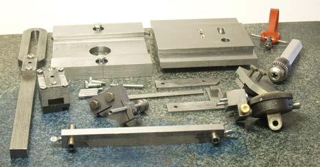
6 Figure 15 Figure 16 Figure 17 Figure 18 Figure 19 Figure 20 ModernMicroscopy.com / Microscopy in the Home Shop 6

7 I have not yet used the adjustable thread lead attachment for threading, but I have tested the linearity of the adjustment using the method mentioned in the previous paragraph. The alignment of the scribed lines indicates when the linkage is square. The nonlinearity is expected to be maximum the farthest the short slide is extended from the square position. The travel of the short slide was measured with a dial indicator having 0.115" travel and " divisions. My initial results were plotted on graph paper with one division per 0.001" of short slide travel. I learned from this initial test that I could not trust the first 0.015" travel of the 0.115" travel. Only the final 0.100" of its travel range was used for a second test. The taper attachment was set at its maximum of 10 degrees and the short slide was initially at the square position. The graph of the results taken at 0.050" increments of carriage travel was quite linear over the 1.00" with 0.097" of short slide travel. The calculated error due to nonlinearity is " for the test conditions. The mathematical analysis is provided below. Mathematical analysis continues on page 8. ModernMicroscopy.com / Microscopy in the Home Shop 7

8 ModernMicroscopy.com / Microscopy in the Home Shop 8
Introduction to Machining: Lathe Operation
 Introduction to Machining: Lathe Operation Lathe Operation Lathe The purpose of a lathe is to rotate a part against a tool whose position it controls. It is useful for fabricating parts and/or features
Lathe. A Lathe. Photo by Curt Newton
 Lathe Photo by Curt Newton A Lathe Labeled Photograph Description Choosing a Cutting Tool Installing a Cutting Tool Positioning the Tool Feed, Speed, and Depth of Cut Turning Facing Parting Drilling Boring
Lathes. CADD SPHERE Place for innovation Introduction
 Lathes Introduction Lathe is one of the most versatile and widely used machine tools all over the world. It is commonly known as the mother of all other machine tool. The main function of a lathe is to
Machining. Module 6: Lathe Setup and Operations. (Part 2) Curriculum Development Unit PREPARED BY. August 2013
 Curriculum Development Unit PREPARED BY. August 2013") Machining Module 6: Lathe Setup and Operations (Part 2) PREPARED BY Curriculum Development Unit August 2013 Applied Technology High Schools, 2013 Module 6: Lathe Setup and Operations (Part 2) Module Objectives
Machining Module 6: Lathe Setup and Operations (Part 2) PREPARED BY Curriculum Development Unit August 2013 Applied Technology High Schools, 2013 Module 6: Lathe Setup and Operations (Part 2) Module Objectives
Lathe is a machine, which removes the metal from a piece of work to the required shape & size HENRY MAUDSLAY
 TURNING MACHINES LATHE Introduction Lathe is a machine, which removes the metal from a piece of work to the required shape & size HENRY MAUDSLAY - 1797 Types of Lathe Engine Lathe The most common form
Ahsanullah University of Science and Technology (AUST) Department of Mechanical and Production Engineering
 Department of Mechanical and Production Engineering") Ahsanullah University of Science and Technology (AUST) Department of Mechanical and Production Engineering LABORATORY MANUAL For the students of Department of Mechanical and Production Engineering 1 st
Ahsanullah University of Science and Technology (AUST) Department of Mechanical and Production Engineering LABORATORY MANUAL For the students of Department of Mechanical and Production Engineering 1 st
Summer Junior Fellowship Experience at LUMS. Maliha Manzoor 13 June 15 July, 2011 LUMS Summer Internship
 Summer Junior Fellowship Experience at LUMS Maliha Manzoor 13 June 15 July, 2011 LUMS Summer Internship Internship Schedule June 13-17: 2D and 3D drawings in AutoCAD June 20-24: 2D and 3D drawings in AutoCAD
Typical Parts Made with These Processes
 Turning Typical Parts Made with These Processes Machine Components Engine Blocks and Heads Parts with Complex Shapes Parts with Close Tolerances Externally and Internally Threaded Parts Products and Parts
Tool & Cutter Grinder
 Tool & Cutter Grinder The Bonelle Tool and Cutter grinder (based on prof. Chaddock s Quorn) can be used to grind most kind of tools from lathe tools to end-mills and reamers. I have been grinding my end-mills
Turning and Lathe Basics
 Training Objectives After watching the video and reviewing this printed material, the viewer will gain knowledge and understanding of lathe principles and be able to identify the basic tools and techniques
Machining. Module 5: Lathe Setup and Operations. (Part 1) Curriculum Development Unit PREPARED BY. August 2013
 Curriculum Development Unit PREPARED BY. August 2013") Machining Module 5: Lathe Setup and Operations (Part 1) PREPARED BY Curriculum Development Unit August 2013 Applied Technology High Schools, 2013 Module 5: Lathe Setup and Operations (Part 1) Module Objectives
Machining Module 5: Lathe Setup and Operations (Part 1) PREPARED BY Curriculum Development Unit August 2013 Applied Technology High Schools, 2013 Module 5: Lathe Setup and Operations (Part 1) Module Objectives
Cross Peen Hammer. Introduction. Lesson Objectives. Assumptions
 Introduction In this activity plan students will develop various machining and metalworking skills by building a two-piece steel hammer. This project will introduce basic operations for initial familiarization
TURNING BORING TURNING:
 TURNING BORING TURNING: FACING: Machining external cylindrical and conical surfaces. Work spins and the single cutting tool does the cutting. Done in Lathe. Single point tool, longitudinal feed. Single
Build a Drill Press Vise
 Youth Explore Trades Skills Introduction This activity plan will develop the student s machining and metalworking skills as they fabricate a multi-piece steel vise. The project will encompass basic lathe
MACHINE TOOL ACCESSORIES
 VERTICAL 5-C COLLET VISE SERIES 344: VERTICAL 3-C COLLET VISE SERIES 344: : 2-1/2 x 7-3/4 Height: 4 Small movement of lever opens or closes collet. 2030000 CAM OPERATED 5-C HORIZONTAL/VERTICAL COLLET FIXTURE
1. The Lathe. 1.1 Introduction. 1.2 Main parts of a lathe
 1. The Lathe 1.1 Introduction Lathe is considered as one of the oldest machine tools and is widely used in industries. It is called as mother of machine tools. It is said that the first screw cutting lathe
By C.W. Woodson From the pages of Model Craftsman magazine June, 1937
 By C.W. Woodson From the pages of Model Craftsman magazine June, 1937 As shown in Fig. 1, the tool post grinder for which plans are given here can be used to finish up delicate work to more accurate dimensions
Chapter 22: Turning and Boring Processes. DeGarmo s Materials and Processes in Manufacturing
 Chapter 22: Turning and Boring Processes DeGarmo s Materials and Processes in Manufacturing 22.1 Introduction Turning is the process of machining external cylindrical and conical surfaces. Boring is a
Trade of Toolmaking Module 2: Turning Unit 1: Machine Controls and Operations Phase 2
 Trade of Toolmaking Module 2: Turning Unit 1: Machine Controls and Operations Phase 2 Published by SOLAS 2014 Unit 1 1 Table of Contents Document Release History... 3 Unit Objective... 4 Introduction...
Bevels & Gauges. Measuring & Marking T-SLIDE BEVEL PLASTIC HANDLE T-SLIDE BEVEL - ABS HANDLE SLIDING BEVEL INDICATOR BEVEL PROTRACTOR
 T-SLIDE BEVEL - ABS HANDLE For determining existing angles or transferring angles onto a workpiece Slotted hardened steel blade allows the user to accommodate a wide range of different size work pieces
Lathe Accessories. Work-holding, -supporting, and driving devices
 46-1 Lathe Accessories Divided into two categories Work-holding, -supporting, and driving devices Lathe centers, chucks, faceplates Mandrels, steady and follower rests Lathe dogs, drive plates Cutting-tool-holding
ROOP LAL Unit-6 Lathe (Turning) Mechanical Engineering Department
 Mechanical Engineering Department") Notes: Lathe (Turning) Basic Mechanical Engineering (Part B) 1 Introduction: In previous Lecture 2, we have seen that with the help of forging and casting processes, we can manufacture machine parts of
Notes: Lathe (Turning) Basic Mechanical Engineering (Part B) 1 Introduction: In previous Lecture 2, we have seen that with the help of forging and casting processes, we can manufacture machine parts of
The new generation with system accessories. Made in Europe!
 1 The new generation with system accessories. Made in Europe! Of cast iron, wide-legged prismatic guide. For vibration-free work even at high loads. Rear flange for mounting the mill/drill head PF 230.
.com More than a machine. Power your life. Precise Centre Metal Lathes. Advanced Technology, Complete
 Precise Centre Metal Lathes. Advanced Technology, Complete Equipment, Easy-to-Operate. This kind of MM-D420X1000 universal metal lathe machine is a fantastic model for small to medium-size turning works
.com More than a machine. Power your life. Precise Centre Metal Lathes. Advanced Technology, Complete
 Precise Centre Metal Lathes. Advanced Technology, Complete Equipment, Easy-to-Operate. This kind of MM-D420X1500 universal metal lathe machine is a fantastic model for small to medium-size turning works
ME MANUFACTURING TECHNOLOGY LABORATORY-I VARUVAN VADIVELAN INSTITUTE OF TECHNOLOGY DHARMAPURI LAB MANUAL
 VARUVAN VADIVELAN INSTITUTE OF TECHNOLOGY DHARMAPURI 636 703 ME 6311 - MANUFACTURING TECHNOLOGY LABORATORY-I REGULATION 2013 LAB MANUAL BRANCH YEAR / SEM MECHANICAL ENGINEERING II YEAR & III SEMESTER D
Other Lathe Operations
 Chapter 15 Other Lathe Operations LEARNING OBJECTIVES After studying this chapter, students will be able to: Safely set up and operate a lathe using various work-holding devices. Properly set up steady
Taig Lathe Instruction Booklet 03J71.00
 Page 1 of 12 Taig Lathe Instruction Booklet 03J71.00 1. Specifications Center Height: 2.250" Distance Between Centers: 9.75" Recommended Motor: 1/6 to 1/4 hp, 1725 rpm, 1/2" arbor Accuracy:?.001" Spindle:
The new generation with system accessories. Made in Germany!
 1 The new generation with system accessories. Made in Germany! For face, longitudinal and taper turning, thread-cutting. For machining steel, brass, aluminium and plastic. Mounting flange for fastening
Precision made in Germany. As per DIN The heart of a system, versatile and expandable.
 1 Precision made in Germany. As per DIN 8606. The heart of a system, versatile and expandable. Main switch with auto-start protection and emergency off. Precision lathe chuck as per DIN 6386 (Ø 100mm).
Building Rudy Kouhoupt s Walking-Beam Engine
 Building Rudy Kouhoupt s Walking-Beam Engine Some time ago I came across a copy of Rudy Kouhoupt s article: "Build this Walking-Beam Engine" (Popular Mechanics August 1969), and decided to try and make
SQ2 User Instructions SQ2 Overview:
 SQ2 User Instructions SQ2 Overview: The stationary circular saws including table, radial and chop saws are arguably the most important tools in the shop. They may also be the most difficult to reliably
HAFCO METALMASTER AL-335F. Centre Lathe. 300 x 910mm Turning Capacity. Product Brochure
 Product Brochure L681 HAFCO METALMASTER AL-335F Centre Lathe 300 x 910mm Turning Capacity Page 1 of 6 Front View Left View Headstock Spindle Speed Levers Control Panel Switches Feed and Thread Gearbox
HAFCO METALMASTER AL-335. Centre Lathe. 300 x 910mm Turning Capacity. Product Brochure
 Product Brochure L183 HAFCO METALMASTER AL-335 Centre Lathe 300 x 910mm Turning Capacity Page 1 of 5 Specifications & Prices are subject to change without notification - 2018-10-08 L183.pdf Headstock Speed
STEEL RULE. Stock TRY SQUARE
 FITTING INTRODUCTION Fitting consists of a handwork involved in fitting together components usually performed at a bench equipped with a vice and hand tools. The matting components have a close relation
Machining The Clapper Pin and Hole, Version 2
 Machining The Clapper Pin and Hole, Version 2 By R. G. Sparber 08/27/2008 Copyleft protects this article. Since I do metal working as a hobby, I am more interested in the journey than the destination.
HOME WORKSHOP HANDBOOK Rugged BENCH GRINDER. By JOEL B. LONG
 6 HOME WORKSHOP HANDBOOK Rugged BENCH GRINDER W By JOEL B. LONG ITH this bench grinder you can keep your cutting tools sharp and do general offhand grinding, and can, with the aid of various attachments,
Turning and Related Operations
 Turning and Related Operations Turning is widely used for machining external cylindrical and conical surfaces. The workpiece rotates and a longitudinally fed single point cutting tool does the cutting.
8.10 Drill Grinding Device
 8.10 Drill Grinding Device Special Accessories 1. Introduction Device can accurately grind precision drill and tools, this drill grinding machine system consists of a motor and grinding wheel head composed
The new generation with system accessories. Made in Germany!
 1 The new generation with system accessories. Made in Germany! For face, longitudinal and taper turning, thread-cutting. For machining steel, brass, aluminium and plastic. Mounting flange for fastening
Unequalled accuracy. The Clausing is a precision machine tool built to tolerances that are tightest in the industry " at spindle nose.
 CATALOG 1258-4 Unequalled accuracy The Clausing is a precision machine tool built to tolerances that are tightest in the industry. Spindle taper (internal).0002" run-out is within.0002" at spindle nose.
Screws. Introduction. 1. Nuts, bolts and screws used to clamp things together. Screws are used for two purposes:
 Screws Introduction Screws are used for two purposes: 1. To clamp things together. 2. To control motion. 1. Nuts, bolts and screws used to clamp things together. Nuts, bolts and screws that are used for
Opti-Turn Lathe & Mill Drill Combination Package Deal
 Product Brochure K146 OPTIMUM TU-2506V-16M Opti-Turn Lathe & Mill Drill Combination Package Deal 250 x 550mm Page 1 of 7 Front View Lathe Toolpost Removed For Milling Application Left View Without Toolpost
Reversing Gear. Shay Reversing Gear
 Shay Nelson Riedel Nelson@NelsonsLocomotive.com Initial: 9/23/03 Last Revised: 06/05/2004 The reversing gear is another one of those pieces I've been putting off. The reason for the postponement was that
AMETAL SHAPER is indispensable for certain METAL SHAPER FOR YOUR SHOP. By S. S. Miner
 METAL SHAPER FOR YOUR SHOP By S. S. Miner AMETAL SHAPER is indispensable for certain machining operations where flat surfaces must be produced within very close limits, such as machining flats on castings,
Flat file. Round file. Hand file. Half -round. Mill file. Square file
 Name Picture Cross section Uses: Cut pattern:: Hand file used for roughing and finishing. It has double cut teeth on two faces, single cut teeth on one edge, and one safe edge Flat file used for roughing
Motor Power (kw / hp): Voltage / Amperage (V / amp): Shipping Dimensions (L x W x H) (cm): Nett Weight (kg): Features
: Voltage / Amperage (V / amp): Shipping Dimensions (L x W x H) (cm): Nett Weight (kg): Features") AL-356V - Centre Lathe 356 x 1000mm Turning Capacity - 51mm Spindle Bore Includes Digital Readout, Quick Change Toolpost & Electronic Variable Speed With Digital Readout Ex GST Inc GST $7,150.00 $7,865.00
AL-356V - Centre Lathe 356 x 1000mm Turning Capacity - 51mm Spindle Bore Includes Digital Readout, Quick Change Toolpost & Electronic Variable Speed With Digital Readout Ex GST Inc GST $7,150.00 $7,865.00
TU-3008G-16M - Opti-Turn Lathe & Mill Drill Combination Package Deal 300 x 700mm Included BF-16AV Mill Head
 TU-3008G-16M - Opti-Turn Lathe & Mill Drill Combination Package Deal 300 x 700mm Included BF-16AV Mill Head Package Deal Ex GST Inc GST $3,980.00 $4,577.00 Package Contents - SAVE $402.50 (Inc) 1 x L691
Brochure Includes: Set-up Instructions Operating Instructions Parts List Fundamentals of Drill Sharpening. Patent 3,952,459
 Patent 3,952,459 Brochure Includes: Set-up Instructions Operating Instructions Parts List Fundamentals of Drill Sharpening Accurately Sharpens most drills bits. Now, with this one low-cost, simple machine,
V-Turn 410/ PRECISION LATHE
 PRECISION LATHE Page 2. Highlights Page 3. Machine construction and feed system Page 3. Main spindle drive Page 4. Toolpost Page 4. Tailstock and auxiliary systems Page 5. 3 Axis Digital Read Out - X.pos
AWMS Inc State Route 41 Northwest, Washington Court House, OH
 AWMS Inc. 5029 State Route 41 Northwest, Washington Court House, OH 43160-8740 18 Jul 2010 DRO PROS 2010-A Harbison Drive #213 Vacaville, CA 95687 DRO PROS, You were most helpful when I was looking to
3" LATHE THREAD CUTTING ATTACHMENT
 3" LATHE THREAD CUTTING ATTACHMENT P/N 3 AN INTRODUCTION TO THREAD CUTTING IN THE REAL WORLD After designing and putting the enclosed screw cutting attachment into production, we sat down and started reading
OPTIMUM TU-2506V. Opti-Turn Bench Lathe. 250 x 550mm Turning Capacity. Product Brochure
 Product Brochure L689 OPTIMUM TU-2506V Opti-Turn Bench Lathe 250 x 550mm Turning Capacity Page 1 of 5 Specifications & Prices are subject to change without notification - 2018-10-30 L689.pdf Front View
SECTION 10: PARTS. Headstock
 33 32 31 30 7 SECTION 10: PARTS 34 23 36 22 15 14 12 35 37 48 39 41 42 50 40 25 38 38 26 39 42 44 41 25 26 40 51 43 52 10 5 53 9 4 1 27 2 21 19 20 Headstock 8 16 11 17 18 14 13 7 6 45 47 46 3 1 P0768001
Review on Design of Jig and Fixture for Turning on Lathe
 Review on Design of Jig and Fixture for Turning on Lathe Gulam Shaikh 1, Siddiki Arshadali 2, Shaikh Masood 3, Thakur Aditya 4, Juberbhai Mansuri 5 1 Theem College of engineering, shaikhgulam45@gmail.com
LANDMARK UNIVERSITY, OMU-ARAN
 LANDMARK UNIVERSITY, OMU-ARAN LECTURE NOTE: DRILLING. COLLEGE: COLLEGE OF SCIENCE AND ENGINEERING DEPARTMENT: MECHANICAL ENGINEERING PROGRAMME: MECHANICAL ENGINEERING ENGR. ALIYU, S.J Course code: MCE
I 640 West. c Offi. pany Phone. c ~ g CHICAGO 6. Ill. M h:tjryant OMPOUND RING BAR SUPPORT. GilBERT C DEarbom ~.
 ll / - M h:tjryant c Offi I 640 West g CHICAGO 6. Ill pany Phone. c ~ GilBERT C DEarbom 2-5566 ~. OMPOUND TIL~:~ BORING, ~~: F:o~~:YH~~~ DRILLING ':~~~N~:E~~7:NE RECTANGULAR TAB ~~~;:E~:~z:T~~L TABLEe
TU-3008G-20M - Opti-Turn Lathe & Mill Drill Combination Package Deal 300 x 700mm Included BF-20AV Mill Head
 TU-3008G-20M - Opti-Turn Lathe & Mill Drill Combination Package Deal 300 x 700mm Included BF-20AV Mill Head Package Deal Ex GST Inc GST $3,850.00 $4,235.00 Package Contents - SAVE $209.00 (Inc) 1 x L691
Universal Machining Chucks. 4-Jaw Vertical
 Universal Machining Chucks 4-Jaw Vertical Parts are gripped firmly by the formed jaws, ensuring high precision (deviation within 0.03mm) Large workpieces can be held tight with the low profile vise body
Technical T-A & GEN2 T-A GEN3SYS APX. Revolution & Core Drill. ASC 320 Solid Carbide. AccuPort 432. Page CONTENTS. Set-up Instructions 256
 Technical ASC 0 Solid Carbide CONTENTS Page Set-up Instructions 6 AccuPort 4 Recommended Speeds & Feeds 60 Guaranteed Application Request Form 99 +44 (0)84 400 900 +44 (0)84 400 0 enquiries@alliedmaxcut.com
INSPECTION AND CORRECTION OF BELLHOUSING TO CRANKSHAFT ALIGNMENT
 INSPECTION AND CORRECTION OF BELLHOUSING TO CRANKSHAFT ALIGNMENT BACKGROUND Proper alignment of the transmission input shaft to the crankshaft centerline is required in order to achieve the best results
SAMPLE. MEM07005C Perform general machining. Learner guide. MEM05 Metal and Engineering Training Package. Version 1.1
 MEM05 Metal and Engineering Training Package MEM07005C Perform general machining Learner guide Version 1.1 Training and Education Support Industry Skills Unit Meadowbank Product code: 5790 Acknowledgments
Referencing 0,0 position
 Page 1 of 11 TITLE: SABRE X-Axis Lead Screw Replacement Procedure Gerber FastFact #: 2013 Supplied by: Gerber Hardware Support Last Modified: March 1, 2011 Summary: The following procedure explains how
An Improved Tool Support for a Harbor Freight Tool Grinder, version 2.2
 An Improved Tool Support for a Harbor Freight Tool Grinder, version 2.2 By R. G. Sparber Copyleft protects this document. 1 Advisory This article was written with a hobby machinist a bit above novice in
2014/2015/2016. The Stuart Half Beam Engine
 2014/2015/2016 The Stuart Half Beam Engine Ian s Home Projects 11/20/2014 The Stuart Turner Half Beam Casting Kit 1 The Stuart Half Beam Engine Table of Contents The Stuart Turner Half Beam Casting Kit...
Now you are only cutting a groove in the lower half of the receiver, if your 46
 The picture on the left shows the shape of the cutter that I ground. The picture on the right shows a picture of a cut off tool replaceable cutting bit that I used as a pattern to grind my own cutter.
Product Brochure For L682D. Description. Features. Auckland: (09)
") AL-336D DELUXE - Centre Lathe 300 x 900mm Turning Capacity Includes Digital Readout, Quick Change Toolpost, Leadscrew Covers, Foot Brake & Cabinet Stand Ex GST Inc GST $5,200.00 $5,980.00 ORDER CODE: MODEL:
AL-336D DELUXE - Centre Lathe 300 x 900mm Turning Capacity Includes Digital Readout, Quick Change Toolpost, Leadscrew Covers, Foot Brake & Cabinet Stand Ex GST Inc GST $5,200.00 $5,980.00 ORDER CODE: MODEL:
TU-2004V - Opti-Turn Bench Lathe 200 x 300mm Turning Capacity Electronic Variable Speeds
 TU-2004V - Opti-Turn Bench Lathe 200 x 300mm Turning Capacity Electronic Variable Speeds Ex GST Inc GST $1,150.00 $1,265.00 ORDER CODE: MODEL: Swing Over Bed (mm): Distance Between Centres (mm): Spindle
INSTRUCTIONS
 IMPORTANT: THIS IS A HIGH PERFORMANCE PART AND IMPROPER INSTALLATION COULD RESULT IN INJURY OR DEATH! NEVER WORK UNDER AN AUTOMOBILE THAT IS NOT PROPERLY SUPPORTED AND BLOCKED FROM ROLLING. NO CREDIT OR
C SERIES LATHES AFFORDABLE. DURABLE. VERSATILE. A line of precision, high performance geared head and variable speed lathes. TURNING PRODUCT CATALOG
 TURNING PRODUCT CATALOG www.clausing-industrial.com 800.323.0972 C SERIES LATHES AFFORDABLE. DURABLE. VERSATILE. A line of precision, high performance geared head and variable speed lathes. HIGH SPEED
Question 1. Flat file. Half -round. Round file. Three square ( triangle ) Needle files. Page 1 of 46
 Needle files. Page 1 of 46") Question 1 Name Picture Cross section Uses: Cut pattern:: Flat file Half -round Round file Three square ( triangle ) Needle files Page 1 of 46 Question 2 The graph shown below is the data collected for
Question 1 Name Picture Cross section Uses: Cut pattern:: Flat file Half -round Round file Three square ( triangle ) Needle files Page 1 of 46 Question 2 The graph shown below is the data collected for
Rotary Fixture M/V/X CLASS LASER SYSTEMS. Installation and Operation Instructions
 Rotary Fixture M/V/X CLASS LASER SYSTEMS Installation and Operation Instructions 02/01/2000 Introduction The Rotary Fixture controls in the Printer Driver are used along with the optional Rotary Fixture
OWNER S MANUAL. Safety. Please read this owner s manual before use and keep it at hand for reference. Warranty
 Please read this owner s manual before use and keep it at hand for reference. OWNER S MANUAL Safety Important safety instructions for using the INCRA Miter5000 Before using the INCRA Miter5000, read and
DRILL GRINDING ATTACHMENT
 DRILL GRINDING ATTACHMENT To suit TM6025Q TOOL AND CUTTER GRINDER OPERATION S MANUAL 1 0º 270º 90º 180º INTRODUCTION Before grinding any cutters, you must set up the attachment to suit the type of cutter
vario drive turn TU 1503V The new compact lathe with electronically adjustable speed. Perfect for the model maker
 turn TU 1503V The new compact lathe with electronically adjustable speed. Perfect for the model maker DC motor Ribbed prism bed made of grey cast iron, inductively hardened and ground Hardened and ground
J D SQUARED INC. NOTCH MASTER Tube and Pipe Notcher Operating Instructions
 Copyright (c) 2006 J D SQUARED INC. www.jd2.com NOTCH MASTER Tube and Pipe Notcher Operating Instructions Angled Notches PATENT PENDING Straight Notches Offset Notches Tube Clamp Slider Tube Clamp Exploded
AL-320G - Bench Lathe, Stand & Tooling Package Deal 320 x 600mm Turning Capacity
 AL-320G - Bench Lathe, Stand & Tooling Package Deal 320 x 600mm Turning Capacity Ex GST Inc GST $3,200.00 $3,680.00 ORDER CODE: MODEL: Swing Over Bed (mm): Distance Between Centres (mm): Spindle Bore (mm):
Useful accessories for lathe and milling systems.
 1 Useful accessories for lathe and milling systems. Nearly all accessories are supplied in wooden boxes. For proper and value preserving storage! Dividing attachment TA 250 For precision lathe PD 250/E,
OPTIMUM TU-3008G. Opti-Turn Bench Lathe. 300 x 700mm Turning Capacity. Product Brochure
 Product Brochure L691 OPTIMUM TU-3008G Opti-Turn Bench Lathe 300 x 700mm Turning Capacity Page 1 of 5 Specifications & Prices are subject to change without notification - 2018-10-30 L691.pdf Right Front
Assembly Instructions 10 X 10 Aluminum Roof Support
 Assembly Instructions 10 X 10 Aluminum Roof Support Aluminum Roof Support Bolt Package 16-5/16 X 2 ¼ SS Bolt 24-5/16 X 1 SS Bolt 40-5/16 SS Nylon Lock Nuts 16-5/16 SS Flat Washers 28-4 ½ Wood Screws 36-1
NABTEB Past Questions and Answers - Uploaded online PAST QUESTIONS AND ANSWERS GENERAL METAL WORK MAY/JUNE 2009
 PAST QUESTIONS AND ANSWERS GENERAL METAL WORK MAY/JUNE 2009 1a. Enumerate TWO safety measures each as regards the use of the following hand tools. 1. Scriber 2. Chisel 3. File 4. Try-square 1. Scriber:
MACHINE TOOLS LAB LABORATORY MANUAL
 Vanjari Seethaiah Memorial Engineering College Patancheru, Medak MACHINE TOOLS LAB LABORATORY MANUAL Department of Mechanical Engineering PREFACE Industrial Revolution has given man a lot many luxuries,
TU-1503V - Opti-Turn Bench Lathe - Mini 150 x 300mm Turning Capacity Electronic Variable Speeds Ex GST Inc GST $ $908.50
 TU-1503V - Opti-Turn Bench Lathe - Mini 150 x 300mm Turning Capacity Electronic Variable Speeds Ex GST Inc GST $790.00 $908.50 ORDER CODE: L685 MODEL: TU-1503V Swing Over Bed (mm): 150 Distance Between
no mm no Dividers with scriber 150 mm NEW Square wedge-shaped knife edges on the length side
 Summer Promotion valid until 30.06.2013 all quoted prices are incl. VAT for deliveries to EU countries to customers with valid VAT-no. and for deliveries in non EU member countries the VAT is not applicable
A Quick-Change Gearbox For The 7x Minilathe
 A Quick-Change Gearbox For The 7x Minilathe Richard Hagenbuch 10 August 2002 This article describes how to a build a quick-change gearbox for your 7X minilathe. I'll describe one that I built as a prototype
Mill Specifications. FEATURE 5000(5100) 5400(5410) 2000 (2010) Max clearance, table to spindle
 5400(5410) 2000 (2010) Max clearance, table to spindle") Mill Specifications FEATURE 5000(5100) 5400(5410) 2000 (2010) Max clearance, table to spindle 8.00" (203 mm) 8.00" (203 mm) 9.00" (229 mm) Throat (without headstock spacer block) Throat (with headstock
Mill Specifications FEATURE 5000(5100) 5400(5410) 2000 (2010) Max clearance, table to spindle 8.00" (203 mm) 8.00" (203 mm) 9.00" (229 mm) Throat (without headstock spacer block) Throat (with headstock
SAMPLE. MEM07005C Perform general machining. Learner guide. MEM05 Metal and Engineering Training Package. Version 1
 MEM05 Metal and Engineering Training Package MEM07005C Perform general machining Learner guide Version 1 Training and Education Support Industry Skills Unit Meadowbank Product code: 5449 Acknowledgments
8-Direction Vertical Milling Column P/N 3580 (Metric P/N 3585)
") WEAR YOUR SAFETY GLASSES FORESIGHT IS BETTER THAN NO SIGHT READ INSTRUCTIONS BEFORE OPERATING Note: This is a supplement to the instructions included in the Sherline Assembly and Instruction Guide that
WEAR YOUR SAFETY GLASSES FORESIGHT IS BETTER THAN NO SIGHT READ INSTRUCTIONS BEFORE OPERATING Note: This is a supplement to the instructions included in the Sherline Assembly and Instruction Guide that
LocoGear. Technical Bulletin - 02 January 11, by LocoGear LIVE STEAM CASTINGS. Tech Bulletin - 02
 LIVE STEAM CASTINGS Tech Bulletin - 02 LocoGear Technical Bulletin - 02 January 11, 2003 2003 by LocoGear John D.L. Johnson 3879 Woods Walk Blvd. Lake Worth, FL 33467-2359 jjohnson@locogear.com www.locogear.com
SECTION 10: PARTS. Headstock
 33 32 31 30 7 SECTION 10: PARTS 34 23 36 22 15 14 12 35 37 48 39 41 42 50 40 25 38 38 26 39 42 44 41 25 26 40 51 43 52 10 5 53 9 4 1 27 2 21 19 20 Headstock 8 16 11 17 18 14 13 7 6 45 47 46 3 1 P0768001
The premier source of parts and accessories for mini lathes and mini mills. Mini Lathe User s Guide. from LittleMachineShop.com
 The premier source of parts and accessories for mini lathes and mini mills. Mini Lathe User s Guide from LittleMachineShop.com Copyright 2002, LittleMachineShop.com All rights reserved. Some photos Copyright
BHJ Products, Inc. Parts List & Instructions
 Product Name: O-Ring Groove Cutter Page 1 of 6 Kit Contents: 1x Cutter Head Assembly with Handle & Adjustable Tool Block 1x Graduated Adjusting Screw 1x Adjustable Tool Holder 1x Carbide Insert (Size of
THREAD CUTTING & FORMING
 THREAD CUTTING & FORMING Threading, Thread Cutting and Thread Rolling: Machining Threads on External Diameters (shafts) Tapping: Machining Threads on Internal Diameters (holes) Size: Watch to 10 shafts
TU-3008G - Opti-Turn Bench Lathe 300 x 700mm Turning Capacity Geared Head-Stock & Enclosed Gearbox
 TU-3008G - Opti-Turn Bench Lathe 300 x 700mm Turning Capacity Geared Head-Stock & Enclosed Gearbox Ex GST Inc GST $3,460.00 $3,979.00 ORDER CODE: MODEL: Swing Over Bed (mm): Distance Between Centres (mm):
STEVENS SUBPLATES. STEVENS ENGINEERING, INC. TOLL-FREE WEB FAX
 STEVENS SUBPLATES Spacing of hole patterns on Stevens accessories is identical to the pattern on Stevens Subplates. Insertion of the pull dowels thru bushed holes in the accessory into corresponding bushed
CV1B Sliding Table Installation and Setup Guide
 CV1B Sliding Table Installation and Setup Guide Tech Mark, Inc 7901 Industry Drive North Little Rock, AR 72117 tel (501) 945-9393 fax (501) 945-0312 www.tech-mark.com email: info@tech-mark.com The CV1B
V twin cylinder steam engine
 V twin cylinder steam engine I got inspired to make this V twin steam engine after reading R. Griffinn s build articles in ME 4396. It is based on Stuart s V-twin double-acting oscillator, but since I
IS THIS HAPPENING IN YOUR TOOL ROOM?
 FIFTY YEARS EXPERIENCE IN MANUFACTURING ACCURATE HIGH SPEED TOOL ROOM LATHES IS EMBODIED IN THIS MODERN MACHINE C IS THIS HAPPENING IN YOUR TOOL ROOM? LOSE observation in a tool room will reveal the use
1640DCL Digital Control Lathe
 1640DCL Digital Control Lathe MACHINE SPECIFICATIONS Multiple Function CNC Lathe 1. Manual Hand wheel Operation 2. CNC G-Code Operation 16.1 swing over bed, 8.6 swing over cross-slide 2.05 diameter hole
HAFCO METALMASTER AL-336. Centre Lathe. 300 x 900mm Turning Capacity. Product Brochure
 Product Brochure L682 HAFCO METALMASTER AL-336 Centre Lathe 300 x 900mm Turning Capacity Page 1 of 5 Specifications & Prices are subject to change without notification - 2018-10-08 L682.pdf Headstock Metric