CHAPTER 6. The main aim of this part of the research work is to experimentally determine
|
|
|
- Alfred Park
- 5 years ago
- Views:
Transcription
1 CHAPTER 6 EXPERTMENTAL STUDY OF COMBINED EFFECT OF BOTH DISTRIBUTED GEOMETRICAL IMPERFECTIONS AND DENT ON BUCKLING STRENGTH OF THIN CYLINDRICAL SHELLS The main aim of this part of the research work is to experimentally determine the combined effect of both distributed geometrical imperfections and localised geometrical imperfections namely dent on buckling strength of thin cylindrical shells subjected to uniform axial compression. In the earlier works, thin cylindrical shells were manufactured by different manufacturing processes such as electro forming (example: Arbocz and B abcock 1969), rolling and welding (example: Han et a1 2006, Athiannan, and Palaninathan 2004), machining process (example: Boote et a1 1997), spin casting (example: Schneider 1996) etc., and also in most of the earlier works, r/t ratios of thn cylindrical shell taken for research work were greater than 100. In some earlier works, for example by Han et al (2006), Boote et a1 (1997), the r/t ratios of the thin cylindrical shell taken for their studies were less than 60. Initially it is planned to manufacture thin cylindrical shells kom stainless steel material and it is found that for inside diameter of around POrnrn, only cast stainless steel tubes are available commercially which may consist blow holes and other casting defects which may affect the aim of our study and hence in hs work aluminum alloy cylindrical shells are selected for study which has similar stressstrain pattern of material property as that of stainless steel. The other reasons for selecting Aluminum alloy seamless tubes are (1) To avoid inclusion of imperfection due to weldment. (2) A1 alloy seamless tubes are available commercially.
2 In this part of the work, to study the combined effects said above, aluminium of Grade A (IS: 737 (1986)) h n cylindrical shells of size internal diameter (ID) 94.6 mm, length 15k1.m and thickness lmm are produced by tuning operation f?om the extruded pipe of size ID 94.6rnrn, length 3m and wall thickness 3m. To avoid the variation in chemical composition and material properties all the cylindrical shell test specimens were manufactured from the same extruded tube. The composition of A1 alloy and its IS Grade are determined by Spectro- chemical analysis. Test report of the same is tabulated in Table 6.1. Table 6.1 Composition of A1 alloy by Spectro Chemical Analysis Alloying Element Percentage of Composition I Silicon I 1ron ) I / copper , I / Manganese I 1 Magnesium / I Chromium I MANUFACTUFUNG OF THIN CYLINDlUCAL SHELLS To produce thin cylindrical shells fiom a extruded tube, the following steps listed below are followed: (i) First, the extruded tube is cut into pieces of 153 mm length. (ii) Length correction to the dimension of 150 i 0.1- on these cylindrical specimens is done by facing operations.
3 (iii) (iv) (v) Grinding operation was done on both the edges of the cylindrical shells to maintain the perpendicularity with respect to the axis of the cylindrical shell and parallelism between top and bottom edges within a tolerance limit of k0.01mm. These pieces are held in between centers on the Lathe Machine using two flanges which have true centers with live and dead centers and also these flanges have sliding fit with the ID of the cylindrical specimens Then, turning operation is performed on the outer surface of the cylindrical specimens to reduce the wall thickness to1 mm. Thus the thm cylindrical shells required for this work are prepared. The final dimensions of the thn cylindrical shell specimens are Length (L) =I50 k 0.01 mm Inner diameter (ID) = 94.6mm (same as extruded pipe ID- the manufacturer assured ID variation is mm) Wall thickness (t)=l * 0.01 mm According to Ref (Cook et a1 1995), if a shell is to qualifjr as thin shell, its r/t ratio should be greater than 20. Hence in th~s work, the cylindrical tube was turned to reduce wall thickness from 3rnrn to Irnm, so that the rit ratio obtained as 47.3 is greater than 20. Reducing the wall thickness of the cylindrical shell further, caused manufacturing difficulties such as, thickness variation of shell due to wobbling of specimen while performing skin turning operation of specimen, clinging specimen to the specimen holder and undesirable noise from the specimen while performing skin turning operation due to elastic deformation of the specimen, even for the small cutting force applied. Because of the above said reasons and also due to limited facilities available to manufacture thin cylindrical shells without undesirable imperfections other than geometrical imperfections, the wall thckness is limited to 1k0.0 1 mm in all the test cylindrical shells manufactured. The hckness variation was verified by cutting the cylindrical shell into strips without plastic deformations and measuring the thicknesses at different locations using digital vernier caliper.
4 6.2 FORMATION OF DENTS ON TEST CYLINDRICAL SHELL SPECIMENS Totally, 18 test cylindrical shells were manufactured and tested, but out of these only six test cylindrical shells for which imperfection measurements taken are presented here. (c) All ckirnensions are in mm Fig. 6.1 Dimensional details of the (a) indenter and (b) die groove for circumferential dent (c) the die groove for longitudinal dent (Details not to scale)
5 A circumferential dent was formed on two (out of six) test thin cylindrical specimens (named as B 1 and B2) at half the height of the specimens using a semi cylindrical mild steel indenter and a mild steel die groove as shown in Fig. 6.1@). similarly, a longitudinal dent was formed on other two test specimens (named as C1 and ~ 2 such ) that the dent center lies at half the height of the test specimen using a similar semi cylindrical indenter and a mild steel die groove as shown in Fig.6.1 (c). The remaining two test cylindrical specimens (named as A1 and A2) were used without dent formation to determine the effect of distributed geometrical imperfections alone. The Fig. 6.1 shows the dimensional details of the indenter and the die groove used to form the dents on test cylindrical shells. 6.3 MEASUREMENT RIG TO MEASURE, GEOMETRICAL IMPERFECTIONS It was planned to get geometrical imperfections data from test cylindrical shells for every 10 mm distance approximately along the longitudinal direction and every 5' along the circumferential direction. But in case of dented cylindrical shell near the dent location longitudinal distance between two rings of measurements is taken as approximately 2rnm. htially it was planned to get imperfections data using Coordinate Measuring Machine (CMM-manual type) because of its measurement accuracy. Later, it is realized that measurement of imperfections mainly depends upon the operator's skill and operator's fatigue to measure thousands of such imperfections data. To overcome these difficulties, an imperfection measurement rig was developed. This rig is designed such that once a test* cylindrical shell and the measuring instrument are loaded on this rig, both of them are not be disturbed until complete measurement is carried out, and also pressure applied on the measuring probe for measurement should be maintained constant to avoid error due to contact Pressure variation. The Fig. 6.2(a) shows the cross section and end view and Fig. 6.2(b) shows 3 D model of geometric imperfection measurement rig.
 FulI sectional front view and side view of Imperfection measurement rig to measure geometrical imperfections @) 3D view of the")
6 This rig includes three major parts as listed below: (a) Main frame with Specimen holder, and (c) Dialholder u Fig. 6.2 (a) FulI sectional front view and side view of Imperfection measurement rig to measure geometrical 3D view of the Imperfection measurement rig

7 6.3.1 Main frame with centers The photo graphic view of the main Erame with centers is shown in Fig 6.3. fie main frame consists of a bed with a guide ways supported on four rigid columns. On one end of the bed a fixed live centre with indexing mechanism is rigidly fixed and on the other end of the bed a movable live centre is mounted. This movable live centre can be moved back and forth on the guide ways by ball screw mechanism and it can be clamped at any location on the bed. The indexing plate consists of 72 holes, so as to index the test cylindrical shell for every 5' about the axis of between centers. A pin - hole mechanism in conjunction with indexing mechanism is used to locate the test cylindrical shell for every 5' in circumferential direction. A dowel pin attached to the fixed live centre is used to transmit positive motion between indexing plate and test specimen. Fig. 6.3 Photo graphic view of main frame with centers Specimen holder The photo graphic view of the specimen holder is shown in Fig 6.4. This is used to mount the test cylindrical shell between the centers. This has a mandrel with a fixed flange at one end. me fixed flange has a step projection for 20mm on its

8 face which is used to locate the test cylindrical shell and this step projection has sliding fit with the ID of the test cylindrical shell. Another guide flange nearer to other end of mandrel is also used to locate the test cylindrical shell. The guide flange also has flat milled surface as shown in Fig to avoid interference with dent on the cylindrical shell. The OD of this guide flange also has clearance fit with the ID of the test specimen. The specimen holder also has a removable clamp flange which has a step projection for 5 mm to locate this removable clamp flange by test specimen. AAer locating the test cylindrical shell and clamp flange, both are held together on the mandrel by clamp screws. Fig. 6.4 Photographic view of specimen holder Dial holder It is planned to measure the imperfections on the cylindrical shell by using a Mitutoyo Digital micron dial indicator. The did holder is designed such a way that it hold the dial indicator and at the same time ensures constant pressure on the dial indicator probe. Fig.6.5 shows the photographic view of dial holder. It has two major parts namely saddle and holding stand. The saddle can be moved back and forth longitudinally on the bed with the help of the guide way of the bed on the main frame. The saddle also has transverse slide ways to move the dial indicator stand

9 in the transverse direction. Both. saddle and transverse slide are clamped together on fie bed, so as to restrain the motion of dial holder on both the directions. The longitudinal location of saddle is measured with the help of vernier caliper. On one end of the transverse slide commercially available dial indicator stand is retrofitted which can provide 3 rotational degree of freedoms for the dial indicator. Fig. 6.5 Photographic view of assembly of dial holder Fig. 6.6 Photographic view of measurement rig loaded with thin cylindrical shell
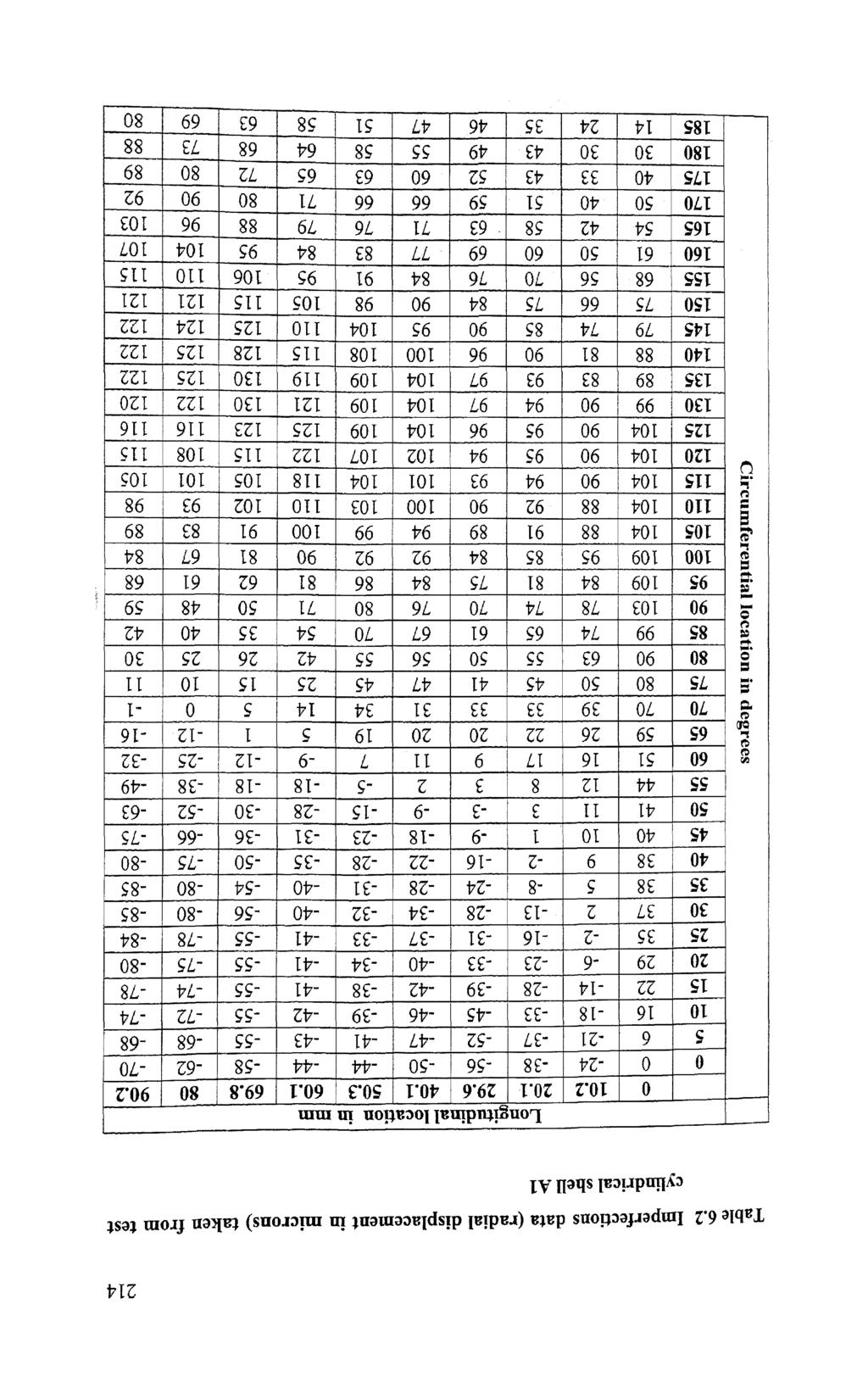
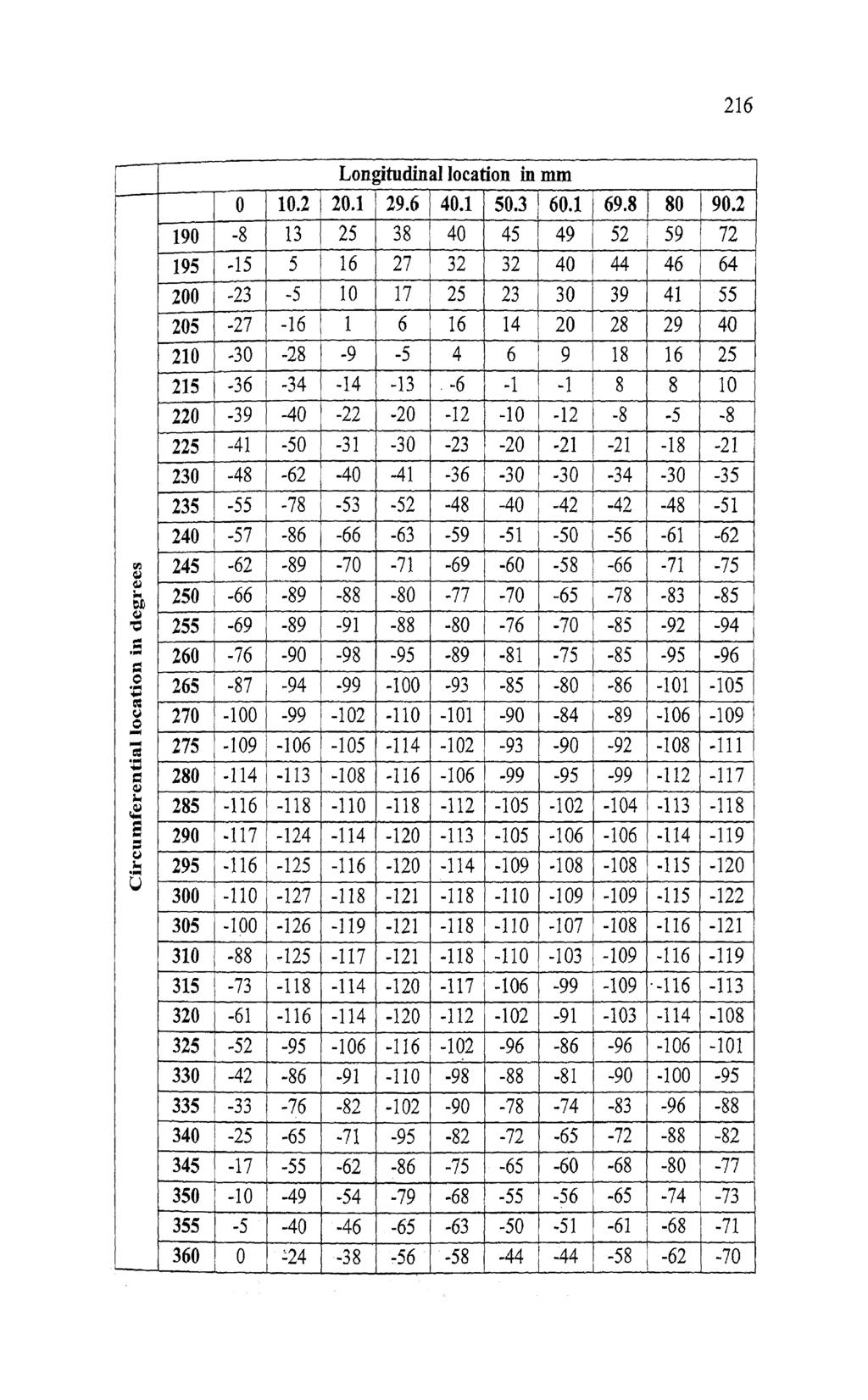
10 ., Fig 6.6 shows photographic view of the finished measurement rig loaded with a test cylindrical shell. Finally, the imperfection measurement rig is checked for its accuracy. Two important aspects of measurements are checked. After the final assembly the run out on the live centre are found to be within 1 micron and taper between centers is found to be 4 microns for a length of 180 m on the test mandrel. 6.4 GEOMETRICAL IMPERFECTION MEASUREMENTS ON THIN CYLINDRICAL SHELLS Using this specially fabricated imperfection measurement rig, imperfection measurement was carried out on six test cylindrical shells. Out of these two test cylindrical shells have a circumferential dent, other two test cylindrical shells have a longitudinal dent and the rest two test cylindrical shells have no dents. Table 6.2 shows sample of imperfection measurement data taken from specimen Al, which had only distributed geometrical imperfection present on the cylindrical shell. Fig 6.7 (a), (b), (c), (d), (e) and (f) are the plots of measured geometrical imperfection data taken from samples Al,A2, B1, B2, C1 and C2 respectively.
11
12
13
14
15 Pig. 6*7 Contd.
16 uxial distonce ix nrm b x in radians Fig. 6.7 Contd...
17 pig. 6.7 (0 Plots of measured geometrical imperfections taken from different test cylindrical shells
18 6.5 EXPERIMENTAL PROCEDURE ADOPTED TO PREDICT BUCJSLING STRENGTH OF THIN CYLINDRICAL SHELLS In this work, 100 kn UTM (FIE Indian make UTN 40 model) was used to predict the buckling strength of cylindrical shells and thls machine has a resolution of 0.1 kn in the loading range of 0 to 40kN. Before performing compression test on utm, the following chechnghnitial settings had been carried out Initial setting (i) On the machine Checking for face out and parallelism of platens of UTM. In this work, initially both top and bottom platens are checked for face out using micron dial indicator and it is found that there are no face outs on the working surface of the platens. The parallelism limit of 10 microns between the platens is ensured. (ii) On specimens Before applying load on the test cylindrical shell, the parallelism between top edge of test specimen and top platen was checked using feeler gauge and it was found to be within the tolerance limit of 30 microns. To ensure extremely slow loading on the cylindrical shell, first, the upward. movement of the lower ram was controlled at rate of approximately 0.5Mm/rnin. And further, to ensure same loading rate, while testing all the other specimens, loading hob of the machine was provided with a stopper at that particular position. A micron dial indicator with its magnetic base is mounted on the machined surface of the bottom ram and the measuring probe of the dial indicator touches the machined surface of the upper fixed ram as shown in Fig On loading, as the lower ram moves upward the dial indicator shows the reduction in gap between the two platens which is nothing but edge displacement applied on the test cylindrical shell on loading.
19 6.6 EXPERIMENTAL PROCEDURE ADOPTED 1. First, the test cylindrical shell was kept centrally and vertically on the bottom platens. 2. The upper platen was moved downward direction nearer to the top edge of the test cylindrical shell rapidly. 3. Then, the lower platen was moved upward direction at a required (low) loading rate of approximately 0.5 dmin by turning the loading knob of the UTM up to the preset stopper position, 4. As soon as the upper edge of the test cylindrical shell touches top platen, at which increase in micron dial indicator reading stops for a while and that micron dial indicator reading (R1) was noted. 5. The uniforrn displacement load from the bottom platen was allowed to apply on the specimen, until the cylindrical shell collapses. 6. As soon as the load applied reaches the limit load condition (at which arm of the live dial indicator of the UTM tends to return back on further loading) both the limit load value on the dial indicator of the UTM and micron dial indicator vafue (R.2) was noted at the same time. R1 -R2 is taken as edge displacement reading. The experimental values of both limit load and edge displacement of all the tested cylindrical shells taken for study are tabulated in Table 6.3. Fig 6.8 shows photograph of the test cylindrical shell compressed axially on the UTM machine between platens to determine the buckling strength experimentally.

20 Fig. 6.8 Photograph of the test cylindrical shell B2 compressed axially on the UTM machine 6.7 RESULTS AND DISCUSSION Test cylindrical shells without dent Both the test cylindrical shells A1 and A2 taken for study (which contained only distributed geometrical imperfections) failed at the maximum load of 6.2 kn by forming partial ring of bulge deformations at both top and bottom edges of the cylindrical shells. The bucme patterns of the test cylindrical shells A1 and A2 are shown in Fig.6.9 (a) and Fig. 6.9(b) respectively. It was found that maximum amplitude of imperfections on test cylindrical shells on positive side (radially outward direction) and negative side (radially inward direction) were 0.145m and 0.195mm respectively with respect to imaginary perfect cylindrical shell of radius 47.8mm and development of imperfections of the same is sown in Fig. 6.7(a). Similarly, maximum amplitude of imperfections on positive and negative directions of the test cylindrical shell A2 was found to be 0.104mm and 0.115mm respectively and development of imperfections of the same is shown in Fig. 6.7(b). Even though the test cylindrical shells A1 and A2 had different imperfections pattern and different amplitudes of imperfections, experimentally showed the buckling strength
21 of 6.2kN, which means that thn cylindrical shells are not very sensitive / less sensitive (i.e., may be less than 0.1~N ) for initial distributed geometrical imperfections. Tlxs insensitiveness or less sensitiveness to initial geometrical imperfections may be due to the fact that the test cylindncal shell taken for study is relatively thick thin shell with ritz47.3. Atluannan and Palaninathan (2004) in their work pointed out that as the r/t ratio decreases the distributed geometrical imperfection effect on buckling strength also decreases. Th~s is once again proved here experimentally. Table 6.3 Experimental Buckling strength of test cylindrical shells Test Cylindrical shell with type of imperfections Test cylindrical shells without dent but containing only distributed geometrical imperfections Sample No. A1 A2 Experimental buckling strength in Edge displacement measurement in mm (at limit load condition) Test cylindrical shells with both distributed geometrical imperfections and a circumferential dent B1 B Test cylindrical shells with distributed geometrical imperfections and a longitudinal dent C1 C Test cylindrical shells with a circumferential dent The test cylindrical shells B1 and B2 having a longitudinal dent failed at the critical buckling load of 5.8kN and 5.9 kn respectively. In both the cases, on reaching the Iimit load condition the first plastic failure of the cylindrical shells was noticed on the dent geometry of cylindrical shell. The buckle pattern of the test

22 cylindrical shells B 1 and B2 are shown in Fig.6.10 (a) and Fig. 6.10(b) respectively. Before performing the buckling test on the test cylindrical shells B 1 and B2, the size of the dent is measured by marking the extent of dent depression. These marks covering the dent depression were then measured on the measurement rig using slide movement of dial holder and the angular moment of the specimens. The size of dent depression on the cylindrical shell B1 was length 32.5mm x width 17.5m1-n x depth 1.742mm. Similarly the size of dent depression on test cylindrical shell B2 was found to be length 23.5mrn x width 16mm x depth 2.05mm. Fig. 6.9 Buckle patterns of (a) test cy llindrical shell A1 and (b) test cylindric shell A2 From the imperfection measuren rent of test cylindrical shell B1, shown in Fig. 6.7(c) it was found that maximu1 n amplitude of imperfection on positj.ve (radially outward direction) and negative side (radially inward direction) was fou nd to be 0.246mm and mm (taken as 1 depth of dent) respectively, with respect to imaginary perfect cylindrical shell of radius 47.8rnrn. Similarly, for B2 ti est
23 cylindrical shell, the positive and negative maximum amplitudes of imperfections were found to be mm and 1.443rnrn (taken as depth of dent) respectively. From the above measurement it is clear that the difference in buckling strengths between B1 and B2 test cylindrical shells may be due to combined effects of increase in length and depth of dent on the test cylindrical shell B1 (compared with dent dimensions on test cylindrical shell B2). Since, it is already proved that in the chapter IV, section 4.2, the effect of circumferential dent width variation on buckling strength is negligible. Also, distributed geometrical imperfection effect is not significant for test cylindrical shells taken for study. In both the cases, on reaching the limit load condition, permanent plastic failure is noticed only at the dent geometry of the test cylindrical shell as shown in Fig As the load applied on the test cylindrical shells is increased beyond the limit load condition, the dent geometry deformed further in radially inward direction and also expanded along the longitudinal axis of dent. And on hrther loading, a partial ring of plastic bulge zone excluding dent effective region (means that the extent of circumferential width over which dent effectiveness can be realized) was formed at the top edge of the cylindrical shell. This part of experimental work further shows that the effect of a circumferential dent on buckling strength and the failure patterns on limit load condition obtained by numerical analyses in the chapter IV, section 4.2, for stainless steel cylindrical shells. i.e., cylindrical shells with a circumferential dent will have lowest buckling strength compared to other angles of inclination of dent and plastic failure is first noticed only at dent geometry.
 test cylindrical shell B1 and (b) test cylindrical shell B2 c) Test cylindrical shells with a longitudinal dent The test cylindrical shells C1 and C2 having a longitudinal")
24 Fig Buckle patterns of (a) test cylindrical shell B1 and (b) test cylindrical shell B2 c) Test cylindrical shells with a longitudinal dent The test cylindrical shells C1 and C2 having a longitudinal dent failed at the critical buckling load of 6.lkN and 6.2 kn respectively. In both the cases, on reaching the limit load condition the failure of the cylindrical shells were noticed with the formation of partial ring of plastic bulge at the top edge of the cylindrical shell. The buckle patterns of the test cylindrical shells C1 and C2 are shown in Fig.6.11 (a) and Fig, 6.11 (b) respectively. Here also, before performing the buckling test on the test cylindrical shells C1 and C2, the size of the dents were measured by marking the extent of dent depression. These marks covering the dent depression were then measured on the measurement rig using slide movement of dial holder and the angular moment of the specimens. The size of dent depression on the cylindrical shell C1 was length 3lmm x width 19.5m x depth 2.536m.m. Similarly the size of dent depression on test cylindrical shell C2 was found to be length 31.5mm x width 17.5m.m x depth 2.05mm. From the imperfection measurement of test cylindrical shell C1, it was found that maximum amplitude of imperfection on positive (radially outward
 respectively.")
25 direction) and negative side (radially inward direction) was found to be 0.288mm and mm (taken as depth of dent) respectively with respect to imaginary perfect cylindrical shell of radius 47.8mm. Similarly for C2 test cylindrical shell, the positive and negative maximum amplitudes of imperfections were found to be 0.132mm and 2.485rnm (taken as depth of dent) respectively. From the above measurement it is clear that the difference in buckling strength between C1 and C2 test cylindrical shells may be due to combined effects of increase in width and depth of dent on the test cylindrical shell C1 compared with dent dimension on test cylindrical shell C2. This part of experimental work further evidences that the effect of a longitudinal dent on buckling strength and the failure patterns obtained from numerical analyses in the chapter IV, section 4.2,for stainless steel cylindrical shells. i.e., Cylindrical shells with a longitudinal dent will have the highest buckling strength compared to other angles of inclination and the cylindrical shells fails by forming ring of plastic zone excluding dent effective region just on reaching the limit load condition. (a) (b) Fig The photographic view of buckled test cylindrical shells C1 and C2 with a longitudinal dent
26 Since, there was no significant variation in length of dent and also it is already proved that in the chapter IV, section 4.2, effect of longitudinal dent length variation on buckling strength is negligible. Also, distributed geometrical imperfection effect is not significant for test cylindrical shells taken for study. In the chapter IV, section 4.2, it was concluded that the buckling strength of cylindrical shells with a longitudinal dent are having almost equal strength as that of the cylindrical shell without dent but with small amplitude of distributed geometrical imperfection only. The reasons for this effect can be assigned as the extent of dent effective region is less compared to circumferential dent and therefore reduction of load support region excluding dent effective region is less and further, the longitudinal dent is oriented along the load direction, which slightly increases the stiffness of the cylindrical shell in the dent region compared to other region of cylindrical shells. The net effect of reduction of load carrying capacity due to the dent effective region and increase in load carrying capacity due to dent stiffness cause the cylindrical shell, with a longitudinal dent to have buckling strength closer to buckling strength of cylindrical shell without dent and at the same time higher buckling strength than cylindrical shells with circumferential dent. The maximum and minimum, variation between longitudinal and circumferential dents is between 3.4% and 6.9% with respect to the lowest bucming strength of 5.8k.N. It was noticed that the load on the cylindrical shells reaches the limit load condition; a partial ring of plastic bulge was noticed at top edge of the cylindrical shells. And on further loading beyond limit load condition the longitudinal dent also plastically deformed forming circwnfaential lobes at half the height of the cylindrical shells i.e. along the transverse axis of the dent and fails like circumferential dent.
DEVELOPMENT OF A NOVEL TOOL FOR SHEET METAL SPINNING OPERATION
 DEVELOPMENT OF A NOVEL TOOL FOR SHEET METAL SPINNING OPERATION Amit Patidar 1, B.A. Modi 2 Mechanical Engineering Department, Institute of Technology, Nirma University, Ahmedabad, India Abstract-- The
Module-4 Lecture-2 Perpendicularity measurement. (Refer Slide Time: 00:13)
") Metrology Prof. Dr. Kanakuppi Sadashivappa Department of Industrial and Production Engineering Bapuji Institute of Engineering and Technology-Davangere Module-4 Lecture-2 Perpendicularity measurement (Refer
Metrology Prof. Dr. Kanakuppi Sadashivappa Department of Industrial and Production Engineering Bapuji Institute of Engineering and Technology-Davangere Module-4 Lecture-2 Perpendicularity measurement (Refer
Corso di Studi di Fabbricazione
 Corso di Studi di Fabbricazione 3a Richiami dei processi tecnologici di trasformazione FUNDAMENTAL OF METAL FORMING 1 METAL FORMING Large group of manufacturing processes in which plastic deformation is
MACHINE TOOL ALIGNMENT TESTS
 MACHINE TOOL ALIGNMENT TESTS 39 MACHINE TOOL TESTING INTRODUCTION: The surface components produced by machining processes are mostly by generation. As a result, the quality of surface produced depends
Lathe. A Lathe. Photo by Curt Newton
 Lathe Photo by Curt Newton A Lathe Labeled Photograph Description Choosing a Cutting Tool Installing a Cutting Tool Positioning the Tool Feed, Speed, and Depth of Cut Turning Facing Parting Drilling Boring
The jigs and fixtures are the economical ways to produce a component in mass production system. These are special work holding and tool guiding device
 The jigs and fixtures are the economical ways to produce a component in mass production system. These are special work holding and tool guiding device Quality of the performance of a process largely influenced
no mm no Dividers with scriber 150 mm NEW Square wedge-shaped knife edges on the length side
 Summer Promotion valid until 30.06.2013 all quoted prices are incl. VAT for deliveries to EU countries to customers with valid VAT-no. and for deliveries in non EU member countries the VAT is not applicable
Drawing. Fig. 1 Drawing
 Drawing Drawing is a metalworking process which uses tensile forces to stretch metal. It is broken up into two types: sheet metal drawing and wire, bar, and tube drawing. The specific definition for sheet
CHAPTER 2 ELECTROMAGNETIC FORCE AND DEFORMATION
 18 CHAPTER 2 ELECTROMAGNETIC FORCE AND DEFORMATION 2.1 INTRODUCTION Transformers are subjected to a variety of electrical, mechanical and thermal stresses during normal life time and they fail when these
Incremental ring rolling to create conical profile rings
 Available online at www.sciencedirect.com ScienceDirect Procedia Engineering 207 (2017) 1248 1253 International Conference on the Technology of Plasticity, ICTP 2017, 17-22 September 2017, Cambridge, United
Tool School - Rotary Draw Bending Tooling. An Engineer s Guide to Bending Tubes
 Tool School - Rotary Draw Bending Tooling An Engineer s Guide to Bending Tubes Tube Form Solutions Tool School Rotary Draw Bending Tooling Tool School Agenda: Introduction To Rotary Draw Bending Engineering
Module-2 Lecture-2 Combination set, Vernier calipers. (Refer Slide Time: 00:16)
") Metrology Prof. Dr. Kanakuppi Sadashivappa Department of Industrial and Production Engineering Bapuji Institute of Engineering and Technology-Davangere Module-2 Lecture-2 Combination set, Vernier calipers
Metrology Prof. Dr. Kanakuppi Sadashivappa Department of Industrial and Production Engineering Bapuji Institute of Engineering and Technology-Davangere Module-2 Lecture-2 Combination set, Vernier calipers
Geometric Dimensioning and Tolerancing
 Geometric Dimensioning and Tolerancing (Known as GDT) What is GDT Helps ensure interchangeability of parts. Use is dictated by function and relationship of the part feature. It does not take the place
DESIGN OF DRAW DIE FOR CYLINDRICAL CUP FORMATION
 DESIGN OF DRAW DIE FOR CYLINDRICAL CUP FORMATION Mr.Bhushan Sanjay Paysheti, Dr. Shekhar Yadgiri Gajjal Abstract For production of sheet metal parts we need various dies (press tools) which will convert
Introduction to Machining: Lathe Operation
 Introduction to Machining: Lathe Operation Lathe Operation Lathe The purpose of a lathe is to rotate a part against a tool whose position it controls. It is useful for fabricating parts and/or features
Metrology Prof. Dr Kanakuppi Sadashivappa Bapuji Institute of Engineering and Technology Davangere. Lecture 24 Measurement of Screw Thread Element
 Metrology Prof. Dr Kanakuppi Sadashivappa Bapuji Institute of Engineering and Technology Davangere Lecture 24 Measurement of Screw Thread Element I welcome you all for the module 6 lecture 2, in this lecture
Lathes. CADD SPHERE Place for innovation Introduction
 Lathes Introduction Lathe is one of the most versatile and widely used machine tools all over the world. It is commonly known as the mother of all other machine tool. The main function of a lathe is to
Module 3 Selection of Manufacturing Processes
 Module 3 Selection of Manufacturing Processes Lecture 4 Design for Sheet Metal Forming Processes Instructional objectives By the end of this lecture, the student will learn the principles of several sheet
ROOP LAL Unit-6 Lathe (Turning) Mechanical Engineering Department
 Mechanical Engineering Department") Notes: Lathe (Turning) Basic Mechanical Engineering (Part B) 1 Introduction: In previous Lecture 2, we have seen that with the help of forging and casting processes, we can manufacture machine parts of
Notes: Lathe (Turning) Basic Mechanical Engineering (Part B) 1 Introduction: In previous Lecture 2, we have seen that with the help of forging and casting processes, we can manufacture machine parts of
Bending. the bend radius is measured to the inner surface of the bent part
 Bending the bend radius is measured to the inner surface of the bent part there is a plane which separates the tension and compression zones. This plane is called neutral axis. The position of neutral
STEEL RULE. Stock TRY SQUARE
 FITTING INTRODUCTION Fitting consists of a handwork involved in fitting together components usually performed at a bench equipped with a vice and hand tools. The matting components have a close relation
Metrology Prof.Dr Kanakuppi Sadashivappa Bapuji Institute of Engineering and Technology Davangere
 Metrology Prof.Dr Kanakuppi Sadashivappa Bapuji Institute of Engineering and Technology Davangere Lecture 33 Electrical and Electronic Comparators, Optical comparators (Refer Slide Time: 00:17) I welcome
March weeks. surcharge for
 March weeks valid until 31.03.2012 all quoted prices are incl. 19% VAT for deliveries in the EU countries to customers with a valid VAT-no. and for deliveries in not EU member countries the VAT is not
10/24/2011. Chapter 3
 Chapter 3 Exact alignment Availability to compensate wear Minimum friction Ease of assembly and economy of manufacture Freedom from restrain Prevention of chip and dirt accumulation Effective lubrication
Precision Double Row Cylindrical Roller Bearings With Tapered Bore
 Roller Bearings With Tapered Bore High precision cylindrical roller bearings are bearings with a low cross section, high load carrying capacity and speed capability. These properties make them particularly
Chapter 24 Machining Processes Used to Produce Various Shapes.
 Chapter 24 Machining Processes Used to Produce Various Shapes. 24.1 Introduction In addition to parts with various external or internal round profiles, machining operations can produce many other parts
TEST SERIES TO EVALUATE THE STRUCTURAL BEHAVIOUR OF ISOBOARD OVER RAFTER SYSTEM
 TEST SERIES TO EVALUATE THE STRUCTURAL BEHAVIOUR OF ISOBOARD OVER RAFTER SYSTEM J A Wium Institute of Structural Engineering 19 November 2007 ISI2007-3 TEST SERIES TO EVALUATE THE STRUCTURAL BEHAVIOUR
LINEAR MEASUREMENT. Prof.H M Prajapati & Prof. A R Sankhla
 LINEAR MEASUREMENT Introduction Classification Based on the type of standard Line measurement End measurement Based on precision Precise Direct: Vernier caliper, Micrometer Indirect: Telescopic gauge,
Metal Working Processes
 Metal Working Processes Bachelor of Industrial Technology Management with Honours Semester I Session 2013/2014 CLASSIFICATION OF MANUFACTURING PROCESSES TOPIC OUTLINE What is Sheet Metal? Sheet Metalworking
Wire and tube Drawing
 Wire and tube Drawing Drawing is an operation in which the cross-section of solid rod, wire or tubing is reduced or changed in shape by pulling it through a die. The principle of this procedure consist
Module 4 General Purpose Machine Tools. Version 2 ME, IIT Kharagpur
 Module 4 General urpose Machine Tools Lesson 24 Forces developing and acting in machine tools Instructional objectives At the end of this lesson, the students will be able to; (i) Identify the sources
Experimental Evaluation of Metal Composite Multi Bolt Radial Joint on Laminate Level, under uni Axial Tensile Loading
 RESEARCH ARTICLE OPEN ACCESS Experimental Evaluation of Metal Composite Multi Bolt Radial Joint on Laminate Level, under uni Axial Tensile Loading C Sharada Prabhakar *, P Rameshbabu** *Scientist, Advanced
ACCESSORIES.
 Rotary, Dividing, & Cross Tables 166 Indexes 167 Dividing Heads 168 Screw Jack Sets 168 Angle Plates & V-Blocks 169 Quick Change Tool Posts & 170-171 CNC Tool Holder Bushings 171 Lathe Chucks 172-177 www.sowatool.com
Application of Guided Wave Technology to Tube Inspection
 ECNDT 2006 - Th.3.1.5 Application of Guided Wave Technology to Tube Inspection T. VOGT, D. ALLEYNE, B. PAVLAKOVIC, Guided Ultrasonics Limited, Nottingham, United Kingdom 1. Introduction Abstract. The inspection
COIL WINDING ISSUES P. Fabbricatore INFN Genova LCD - Magnet 13Oct09. Coil winding issues
 Coil winding issues Based on experience acquired with CMS coil construction, some preliminary considerations about the envisaged winding (and in general manufacturing) issues of a large superconducting
Modification Of High Precision Tube Roller Mill Tool For Higher Production
 Modification Of High Precision Tube Roller Mill Tool For Higher Production B.Shirish 1, B.Mahasenadhipathi 2 and S.S.Das 3 1 PG Student, Department of Mechanical Engineering, Sreenidhi Institute of Science
125 years of innovation. Cylindricity. Global Excellence in Metrology
 125 years of innovation Cylindricity Cylindricity Contents Introduction Instrument Requirements Reference Cylinders Cylindricity Parameters Measurement Techniques & Methods Measurement Errors & Effects
Student, Department of Mechanical Engineering, Knowledge Institute of Technology, Salem, Tamilnadu (1,3)
") International Journal of Scientific & Engineering Research, Volume 7, Issue 5, May-2016 11 Combined Drilling and Tapping Machine by using Cone Mechanism N.VENKATESH 1, G.THULASIMANI 2, S.NAVEENKUMAR 3,
International Journal of Scientific & Engineering Research, Volume 7, Issue 5, May-2016 11 Combined Drilling and Tapping Machine by using Cone Mechanism N.VENKATESH 1, G.THULASIMANI 2, S.NAVEENKUMAR 3,
Module 1. Classification of Metal Removal Processes and Machine tools. Version 2 ME IIT, Kharagpur
 Module 1 Classification of Metal Removal Processes and Machine tools Lesson 2 Basic working principle, configuration, specification and classification of machine tools Instructional Objectives At the end
V twin cylinder steam engine
 V twin cylinder steam engine I got inspired to make this V twin steam engine after reading R. Griffinn s build articles in ME 4396. It is based on Stuart s V-twin double-acting oscillator, but since I
Technical Manual. ETP-CLASSIC incl type R. Content
 Technical Manual ETP-CLASSIC incl type R Content Technical parts description...2 Mounting/dismantling tips...4 Design suggestions...7 Tolerances...13 Central bolt...15 Torsional stiffness...16 Screw pitch
Building Rudy Kouhoupt s Walking-Beam Engine
 Building Rudy Kouhoupt s Walking-Beam Engine Some time ago I came across a copy of Rudy Kouhoupt s article: "Build this Walking-Beam Engine" (Popular Mechanics August 1969), and decided to try and make
Question 1. Flat file. Half -round. Round file. Three square ( triangle ) Needle files. Page 1 of 46
 Needle files. Page 1 of 46") Question 1 Name Picture Cross section Uses: Cut pattern:: Flat file Half -round Round file Three square ( triangle ) Needle files Page 1 of 46 Question 2 The graph shown below is the data collected for
Question 1 Name Picture Cross section Uses: Cut pattern:: Flat file Half -round Round file Three square ( triangle ) Needle files Page 1 of 46 Question 2 The graph shown below is the data collected for
A Mathematical Model to Determine Sensitivity of Vibration Signals for Localized Defects and to Find Effective Number of Balls in Ball Bearing
 A Mathematical Model to Determine Sensitivity of Vibration Signals for Localized Defects and to Find Effective Number of Balls in Ball Bearing Vikram V. Nagale a and M. S. Kirkire b Department of Mechanical
CH # 8. Two rectangular metal pieces, the aim is to join them
 CH # 8 Screws, Fasteners, and the Design of Non-permanent Joints Department of Mechanical Engineering King Saud University Two rectangular metal pieces, the aim is to join them How this can be done? Function
MANUFACTURING TECHNOLOGY
 MANUFACTURING TECHNOLOGY UNIT II SHEET METAL FORMING PROCESSES Sheet metal Process in detail Cutting (Shearing) Operations Manufacturing Technology In this operation, the work piece is stressed beyond
Flat file. Round file. Hand file. Half -round. Mill file. Square file
 Name Picture Cross section Uses: Cut pattern:: Hand file used for roughing and finishing. It has double cut teeth on two faces, single cut teeth on one edge, and one safe edge Flat file used for roughing
CONTENTS PRECAUTIONS BEFORE STARTING OPERATION PREPARATION FOR OPERATION CAUTIONS ON USE OPERATION
 CONTENTS PRECAUTIONS BEFORE STARTING OPERATION ------------------------------------- 1 PREPARATION FOR OPERATION 1. Adjustment of needle bar stop position ---------------------------------------------------------
4. PRESS AND PRESS WORK
 4. PRESS AND PRESS WORK Q. Which are the materials used for press work? GALVANISED IRON Zinc-coated iron is known as "galvanised iron"'. This soft steel sheet is popularly known as Gl sheet. Applications:
WHAT? WHERE? HOW?
 JIGS WHAT? WHERE? HOW? Introduction Mass production aims at high productivities to reduce unit cost and inter-changeabilites to facilitate easy assembly. Jigs are useful in mass production. They provide
INDEX. S.No. Name of the Experiment Page No.
 MACHINE TOOLS LAB INDEX S.No. Name of the Experiment Page No. 1 Step Turning and Taper Turning on Lathe 2 Thread Cutting and Knurling on Lathe 3 Machining Flat Surface using Shaper Machine 4 Manufacturing
Each Height Master is supplied with a gauge block for reference-height setting. Fitted wooden case supplied. SPECIFICATIONS
 Height Master SRIS 515 Models with the the staggered arrangement of blocks have two measuring faces on the same level, one facing up and the other down (except for 515-310). Staggered 20mm blocks (movable)
SINUMERIK live: turning technologies longitudinal turning and plunge-turning. Differences and use with SINUMERIK Operate
 SINUMERIK live: turning technologies longitudinal turning and plunge-turning Differences and use with SINUMERIK Operate siemens.com/cnc4you SINUMERIK live - Application technology explained in an easily
CHAPTER 5 FAULT DIAGNOSIS OF ROTATING SHAFT WITH SHAFT MISALIGNMENT
 66 CHAPTER 5 FAULT DIAGNOSIS OF ROTATING SHAFT WITH SHAFT MISALIGNMENT 5.1 INTRODUCTION The problem of misalignment encountered in rotating machinery is of great concern to designers and maintenance engineers.
HIGH ENERGY RATE FORMING PROCESSES
 HIGH ENERGY RATE FORMING PROCESSES In these forming processes large amount of energy is applied for a very short interval of time. Many metals tend to deform more readily under extra fast application of
HMP-200 BENDER INSTRUCTION SET
 HMP-200 BENDER INSTRUCTION SET HMP-200 BENDER ASEMBLY INSTRUCTIONS STEP 1 STEP 2 BOLT LEFT SIDE PLATE TO BASE AS SHOWN WITH 1/2 x20 HEX BOLT & FLAT WASHER WELD BASE TO PLATE ON EACH SIDE NOTE: OFFSET HOLE
Work Holding Principles ITCD Rajeev Madhavan Nair
 Work Holding Principles ITCD 301-001 Work Holding One of the most important elements of the machining process Work holder includes all devices that hold, grip or chuck a work piece to perform a manufacturing
TURNING BORING TURNING:
 TURNING BORING TURNING: FACING: Machining external cylindrical and conical surfaces. Work spins and the single cutting tool does the cutting. Done in Lathe. Single point tool, longitudinal feed. Single
Ahsanullah University of Science and Technology (AUST) Department of Mechanical and Production Engineering
 Department of Mechanical and Production Engineering") Ahsanullah University of Science and Technology (AUST) Department of Mechanical and Production Engineering LABORATORY MANUAL For the students of Department of Mechanical and Production Engineering 1 st
Ahsanullah University of Science and Technology (AUST) Department of Mechanical and Production Engineering LABORATORY MANUAL For the students of Department of Mechanical and Production Engineering 1 st
Development of Orbital Drilling for the Boeing 787
 Copyright 2008 SAE International 08FAS-0006 Development of Orbital Drilling for the Boeing 787 Eric Whinnem Gary Lipczynski The Boeing Company Ingvar Eriksson Novator AB ABSTRACT The new materials and
An Adjustable Threading Feed Attachment for a Lathe Without Metric Threading Capability, by Ted Clarke
 An Adjustable Threading Feed Attachment for a Lathe Without Metric Threading Capability by Ted Clarke Metric pitch threads, with the exception of the Royal Microscopical Society (RMS) 36 threads per inch
COMMON SYMBOLS/ ISO SYMBOL ASME Y14.5M ISO FEATURE CONTROL FRAME DIAMETER/ SPHERICAL DIAMETER/ AT MAXIMUM MATERIAL CONDITION
 1 82 COMMON SYMBOLS/ Shown below are the most common symbols that are used with geometric tolerancing and other related dimensional requirements on engineering drawings. Note the comparison with the ISO
Chapter 24. Machining Processes Used to Produce Various Shapes: Milling
 Chapter 24 Machining Processes Used to Produce Various Shapes: Milling Parts Made with Machining Processes of Chapter 24 Figure 24.1 Typical parts and shapes that can be produced with the machining processes
Available online at ScienceDirect. Procedia Engineering 81 (2014 )
") Available online at www.sciencedirect.com ScienceDirect Procedia Engineering 81 (2014 ) 641 646 11th International Conference on Technology of Plasticity, ICTP 2014, 19-24 October 2014, Nagoya Congress
Available online at www.sciencedirect.com ScienceDirect Procedia Engineering 81 (2014 ) 641 646 11th International Conference on Technology of Plasticity, ICTP 2014, 19-24 October 2014, Nagoya Congress
Reversing Gear. Shay Reversing Gear
 Shay Nelson Riedel Nelson@NelsonsLocomotive.com Initial: 9/23/03 Last Revised: 06/05/2004 The reversing gear is another one of those pieces I've been putting off. The reason for the postponement was that
HAND TOOLS. Moore & Wright Engineers Squares. For more information visit Features. WORKSHOP SQUARES: Grade B DIMENSIONS TABLE (MM)
") Moore & Wright Engineers Squares Precision ground blade and stock Blind rivetted construction Hardened and tempered blades 3" & 4" available in Retail Packs 4006 WORKSHOP SQUARES: Grade B Blade Length
Moore & Wright Engineers Squares Precision ground blade and stock Blind rivetted construction Hardened and tempered blades 3" & 4" available in Retail Packs 4006 WORKSHOP SQUARES: Grade B Blade Length
The master for the control of the gears
 The master for the control of the gears The master gear is a special gear that is coupled with the gear to be checked in order to highlight the construction errors or serious imperfections that may compromise
DESIGN OF MACHINE MEMBERS-I
 Code No: R31035 R10 Set No: 1 JNT University Kakinada III B.Tech. I Semester Regular/Supplementary Examinations, Dec - 2014/Jan -2015 DESIGN OF MACHINE MEMBERS-I (Mechanical Engineering) Time: 3 Hours
Fluid Sealing Association
 Fluid Sealing Association STANDARD FSA-MG-501-02 STANDARD TEST METHOD FOR INWARD BUCKLING OF SPIRAL-WOUND GASKETS 994 Old Eagle School Road, Suite 1019 Wayne, Pennsylvania 19087-1866 Phone: (610) 971-4850
User s Guide. Silent Tools. turning products
 User s Guide Silent Tools turning products Introduction This guide will help you to use dampened boring bars (Silent Tools) to achieve the best possible results in internal turning. Silent Tools dampened
Metal Stamping Glossary
 Metal Stamping Glossary Alloy - A substance that has metallic properties and is composed of two or more chemical elements of which at least one is an elemental metal. Annealing - A process involving the
0.20. Record Page 1 of 19
 Page 1 of 19 Page 2 of 19 Page 3 of 19 Page 4 of 19 Page 5 of 19 ASME BPVC.III.1.ND-2015 Page 6 of 19 ð15þ Figure ND-3325-1 Some Acceptable Types of Unstayed Flat Heads and Covers GENERAL NOTE: The illustrations
ACCREDITATION FACILITY AUDIT CHECKLIST
 ACCREDITATION FACILITY AUDIT CHECKLIST Institution Name: Date: Designated Trade: Machinist AC #: Contact: Location: Course Duration: of weeks: of hours total: of hours per day: Instructor(s) of Students
2 Cylinder Slidevalve Steam Engine
 2 Cylinder Slidevalve Steam Engine By Thor Hansen After making a slide valve engine that I managed to get running I decided to try and make a 2-cylinder version. Since the first one was a vertical steam
Module-2 Lecture-1 Angle plate, steel rule, spring calipers. (Refer Slide Time: 00:14)
") Metrology Prof. Dr. Kanakuppi Sadashivappa Department of Industrial and Production Engineering Bapuji Institute of Engineering and Technology-Davangere Module-2 Lecture-1 Angle plate, steel rule, spring
Metrology Prof. Dr. Kanakuppi Sadashivappa Department of Industrial and Production Engineering Bapuji Institute of Engineering and Technology-Davangere Module-2 Lecture-1 Angle plate, steel rule, spring
TECH SHEET PEM - REF / TESTING CLINCH PERFORMANCE. SUBJECT: Testing clinch performance of self-clinching fasteners.
 PEM - REF / TESTING CLINCH PERFORMANCE SUBJECT: Testing clinch performance of self-clinching fasteners. A self-clinching fastener s performance can be divided into two major types. The first is self-clinching
Machining. Module 6: Lathe Setup and Operations. (Part 2) Curriculum Development Unit PREPARED BY. August 2013
 Curriculum Development Unit PREPARED BY. August 2013") Machining Module 6: Lathe Setup and Operations (Part 2) PREPARED BY Curriculum Development Unit August 2013 Applied Technology High Schools, 2013 Module 6: Lathe Setup and Operations (Part 2) Module Objectives
Machining Module 6: Lathe Setup and Operations (Part 2) PREPARED BY Curriculum Development Unit August 2013 Applied Technology High Schools, 2013 Module 6: Lathe Setup and Operations (Part 2) Module Objectives
The New Unrivalled SRB Titan Magnet Clamps & Spartan Composite Adjustable Sideforms
 SRB PRECAST FORMWORK The New Unrivalled SRB Titan Magnet Clamps & Spartan Composite Adjustable Sideforms Australian Designed and Manufactured to suite Robust and Demanding requirements of the Precast Industry.
Lecture 15. Chapter 23 Machining Processes Used to Produce Round Shapes. Turning
 Lecture 15 Chapter 23 Machining Processes Used to Produce Round Shapes Turning Turning part is rotating while it is being machined Typically performed on a lathe Turning produces straight, conical, curved,
Joining Metals with Stamping Dies
 733563AA Joining Metals with Stamping Dies A Die Builder s Guide to BTM s sheet metal clinch joining systems. A supplement for BTM s Tog-L-Loc and Lance-N-Loc Tooling Catalogs to assist in the proper application
Steel Plate in Oil Rig Blowout Preventer Valves
 Design Problem Steel Plate in Oil Rig Blowout Preventer Valves Introduction Design for Performance Alloy selection Radii and stress reduction Design for Production Mould method Orientation and cores Controlling
Comparative Measurement
 Comparative Measurement H-1 TESA YA Bore Gauges TESA YA Complete Instrument SETS Specially designed for small bores from 0,47 up to 12,20 - Checking of dimension and bore form errors through 2-point measuring
Joining Metals with Stamping Dies
 733563 Joining Metals with Stamping Dies A Die Builder s Guide to BTM Corporation s sheet metal clinch joining systems. A supplement for BTM Corporation s Tog-L-Loc and Lance-N-Loc Tooling Catalogs to
Experimental and numerical investigation of tube sinking of rectangular tubes from round section
 International Journal of Engineering and Technology sciences (IJETS) ISSN 2289-4152 Academic Research Online Publisher Research Article Experimental and numerical investigation of tube sinking of rectangular
VISUAL GUIDE MANUAL DRO INSTALLATION ON LATHE / TURNING MACHINE. By ebay ID: TheDroStore
 VISUAL GUIDE MANUAL DRO INSTALLATION ON LATHE / TURNING MACHINE By ebay: TheDroStore info@thedrostore.com 1 2. Basic Installation Principles scale should be centered and be aligned such that it could cover
Moment-Resisting Connections In Laminated Veneer Lumber (LVL) Frames
 Frames") Moment-Resisting Connections In Laminated Veneer Lumber (LVL) Frames Andy van Houtte Product Engineer-LVL Nelson Pine Industries Nelson, NZ Andy Buchanan Professor of Civil Engineering Peter Moss Associate
Moment-Resisting Connections In Laminated Veneer Lumber (LVL) Frames Andy van Houtte Product Engineer-LVL Nelson Pine Industries Nelson, NZ Andy Buchanan Professor of Civil Engineering Peter Moss Associate
Hail University College of Engineering Department of Mechanical Engineering. Sheet-Metal Forming Processes and Equipment. Ch 16
 Hail University College of Engineering Department of Mechanical Engineering Sheet-Metal Forming Processes and Equipment Ch 16 Sheet-Metal Forming Products made of sheet metals are all around us. They include
LS-DYNA USED TO ANALYZE THE MANUFACTURING OF THIN WALLED CANS AUTHOR: CORRESPONDENCE: ABSTRACT
 LS-DYNA USED TO ANALYZE THE MANUFACTURING OF THIN WALLED CANS AUTHOR: Joachim Danckert Department of Production Aalborg University CORRESPONDENCE: Joachim Danckert Department of Production Fibigerstraede
Two Categories of Metal Casting Processes
 Two Categories of Metal Casting Processes 1. Expendable mold processes - mold is sacrificed to remove part Advantage: more complex shapes possible Disadvantage: production rates often limited by time to
PRESS & PRESS WORK
 Topic and Contents Hours Marks 2.1 Introduction 08 Marks Materials used in press work for automobile applications. Classifications of presses and terminology used in presses Major parts of Fly press 2.2
1/2/2016. Lecture Slides. Screws, Fasteners, and the Design of Nonpermanent Joints. Reasons for Non-permanent Fasteners
 Lecture Slides Screws, Fasteners, and the Design of Nonpermanent Joints Reasons for Non-permanent Fasteners Field assembly Disassembly Maintenance Adjustment 1 Introduction There are two distinct uses
Sheet Metal Tools. by:prem Mahendranathan
 Sheet Metal Tools by: SHEET METAL TOOL KIT SHEET METAL TOOLS Rivet Gun 3/32, 1/8, 5/32, 3/16",Cupped Set Mini Bucking Bar Footed Heel-Toe Bucking Bar Air Tool Oil Mechanics Tool Bag High-Speed Air Drill
Heat Exchanger & Boiler Tube Inspection Techniques
 Overview For the in-service inspection of ferromagnetic, non-ferromagnetic and fin-fan tubes, the following advanced techniques offer high defect detection capabilities and accurate defect analysis: Multiple
Metrology Prof. Dr Kanakuppi Sadashivappa Bapuji Institute of Engineering and Technology Davangere
 Metrology Prof. Dr Kanakuppi Sadashivappa Bapuji Institute of Engineering and Technology Davangere Lecture 37 Universal Measuring Machine (UMM) and Coordinate Measuring Machine (CMM) (Refer Slide Time:
SRF. Deliverable : Single cell spinning parameter defined. V. Palmieri. Laboratori Nazionali di Legnaro INSTITUTO NAZIONALE DI FISICA NUCLEARE
 SRF Deliverable 3.1.4.3: Single cell spinning parameter defined V. Palmieri Laboratori Nazionali di Legnaro INSTITUTO NAZIONALE DI FISICA NUCLEARE Abstract Seamless cavities can be spun from either blanks
Design for Quality, Manufacturing and Assembly Prof. G.Saravana Kumar Department of Engineering Design Indian Institute of Technology, Madras
 Design for Quality, Manufacturing and Assembly Prof. G.Saravana Kumar Department of Engineering Design Indian Institute of Technology, Madras Lecture 20 Estimation of Mold Cost for Injection Molding (Dixon
How to use. Use example. Non-scratch sheet prevents die marks. Tight-knit super fiber provides a working life of many hundreds cycles.
 How to use Small to Medium dies Fix Kizu-non on the die shoulder with masking tape. Should not be crinkled. *Cut Kizu-non with scissors for desired length. Large dies Fix Kizu-non on each die shoulders.
IMPROVEMENT OF DETECTION OF SMALL DEFECTS LOCATED NEAR OR FAR FROM WELDS OF MAGNETIC STEAM GENERATOR TUBES USING REMOTE FIELD EDDY CURRENT
 12 th A-PCNDT 2006 Asia-Pacific Conference on NDT, 5 th 10 th Nov 2006, Auckland, New Zealand IMPROVEMENT OF DETECTION OF SMALL DEFECTS LOCATED NEAR OR FAR FROM WELDS OF MAGNETIC STEAM GENERATOR TUBES
Trade of Toolmaking. Module 5: Press Tools, Jigs & Fixtures, Mouldmaking Unit 5: Jigs and Fixtures Phase 2. Published by
 Trade of Toolmaking Module 5: Press Tools, Jigs & Fixtures, Mouldmaking Unit 5: Jigs and Fixtures Phase 2 Published by SOLAS 2014 Unit 5 1 Table of Contents Document Release History... 3 Unit Objective...
SAGITTAL SAW BACKGROUND OF THE INVENTION
 SAGITTAL SAW BACKGROUND OF THE INVENTION Sagittal bone saws function through angular oscillation of the saw cutting blade, and are used primarily in applications that require plunge cutting of bone. However,