EMC Training. Ing Angelo Cereser Mobile:
|
|
|
- Martin Todd
- 5 years ago
- Views:
Transcription


1 EMC Training Ing Angelo Cereser Mobile: Dott Mirko Bombelli Mobile:
2 Agenda Introduzione alle misure EMI Terminologia; precompliance verso full compliance Setup di misura: emissioni radiate e condotte CISPR & MIL461F (Cenni) L analizzatore di spettro per le misure EMI Time Scan mode Differenti metodi di scansione ( swept, stepped, time domain ) Approccio veloce al precompliance Real Time Analysis Definizione di Real Time, Real Time operation, Overlap processing
3 Agenda Introduzione alle misure EMI Terminologia; precompliance verso full compliance Setup di misura: emissione radiate e condotte CISPR & MIL461F (Cenni) L analizzatore di spettro per le misure EMI Time Scan mode Differenti metodi di scansione ( swept, stepped, time domain ) Approccio veloce al precompliance Real Time Analysis Definizione di Real Time, Real Time operation, Overlap processing

, a")
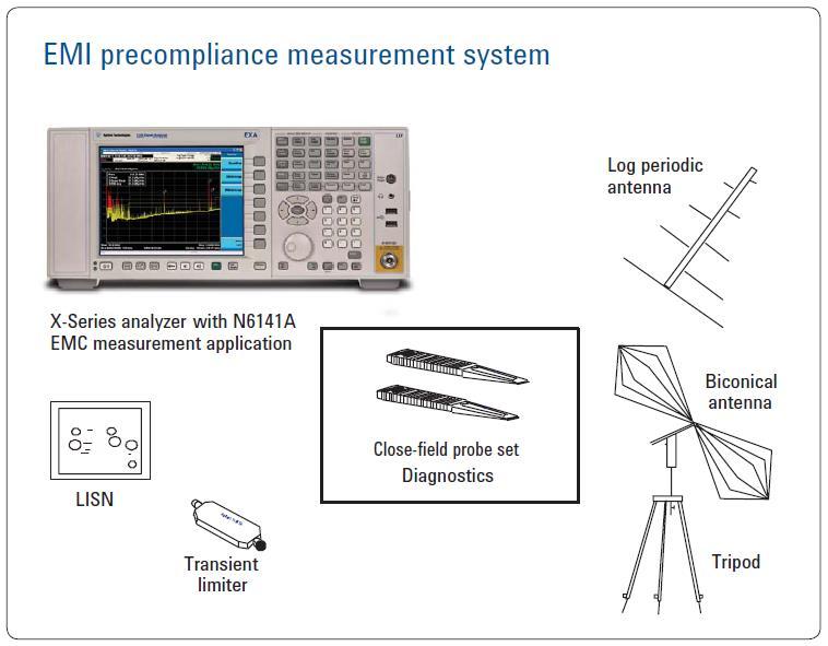
4 Pre-compliance vs. Full compliance measurements Pre-Compliance measurements Evaluate the conducted and radiated emissions of a device using correct detectors and bandwidths before going to a test house for compliance testing Full Compliance measurements Full compliance testing requires a receiver that meets all the requirements of CISPR (response to a CISPR pulse gen), a qualified open area test site or semi anechoic chamber and an antenna tower and turntable to maximize EUT signals.
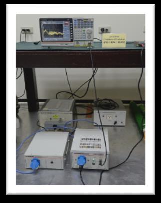
5 Precompliance Conducted Emission Testing set-up
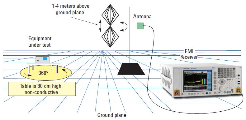
6 Precompliance Radiated Emission Testing set-up
7 Compliance EMI receiver requirements A CISPR receiver must have the following functionality in the range 9 khz - 18 GHz: A normal +/- 2 db absolute accuracy CISPR-specified resolution bandwidths (-6 db) Peak, quasi-peak, EMI average, and RMS average detectors Specified input impedance with a nominal value of 50 ohms; deviations specified as VSWR Be able to pass product immunity in a 3 V/m field Be able to pass the CISPR pulse test (implies pre-selector below 1 GHz) Other specific harmonic and intermodulation requirements
8 Receiver requirements above 1 GHz 1 MHz bandwidth for measurements No quasi-peak detector No CISPR pulse test, meaning no additional pre-selector required excellent sensitivity According to current FCC regulations, the maximum test frequency is the fifth harmonic of the highest clock frequency for an unintentional radiator (for example, computers without wireless connectivity) and the tenth harmonic for an intentional radiator (such as a cellular phone or wireless LAN).
9 MIL STD 461F Spectrum Analyzer use allowed (and commonly used) - need to ensure measurement linearity (avoid overloads) - need to have sufficient sensitivity (may need preamp) Requires MIL Bandwidths Requires Peak Detector +/- 2dB amp accuracy, +/- 2% frequency accuracy Dwell times specified in document
10 Agenda Introduzione alle misure EMI Terminologia; precompliance verso full compliance Setup di misura: emissione radiate e condotte CISPR & MIL461F (Cenni) L analizzatore di spettro per le misure EMI Time Scan mode Differenti metodi di scansione ( swept, stepped, time domain ) Approccio veloce al precompliance Real Time Analysis Definizione di Real Time, Real Time operation, Overlap processing
11 Theory of Operation RF input attenuator mixer IF gain IF filter (RBW) envelope detector Input signal Pre-Selector Or Low Pass Input Filter local oscillator Log Amp video filter sweep generator Crystal Reference Oscillator Swept Spectrum Analyzer Block Diagram ADC, Display & Video Processing
12 All Digital IF Advantages RF Section ADC Flexibility: RBW filtering in 10% steps Filters with better selectivity Multiple operation modes (Swept, FFT, VSA, NFA) Accuracy: Log conversion practically ideal No drift errors; increased repeatability FFT IF/BB Section on ASIC Speed: When Swept mode is slow, go FFT
13 Digital IF Improves Amplitude Accuracy Input Connector ADC DSP RF Input Attenuator 2 db Steps Pre-selector Frequency Dependent Frequency Independent Amplitude Uncertainty Ref Level Switching RBW Switching Display Scale Fidelity N9038A Receiver 0dB Analog IF (older receivers) <= +/- 1dB +/-.05dB <= +/-.5dB +/-.15dB <= +/-.85dB Digital IF improves Amplitude Accuracy: Ref Level switching uncertainty (IF gain) Level correction digitally synthesized RBW filter switching uncertainty RBWs all digitally synthesized Display scale fidelity (Log Amp) Log response & display scaling digitally synthesized Downconversion IF Filter IF Gain Log Amp Video Filter Log ADC
14 EMI Receiver Block Diagram ( Keysight MXE ) Input 2 Pre-amp Input 1 Transient Limiter Attenuation RF Preselector Digital IF Filter Digital Detectors FFT MXE Analog IF Filter ADC Swept vs. FFT Digital Log Amp

15 RF Pre-selection (RF input filtering) Purpose of RF pre-selection Help to prevent overload by reducing total energy at input mixer RF preselector tracks the center frequency of the EMI receiver The bandwidth of the RF preselector is wider than the widest RBW used Useful in measuring broadband signals Types of filters used in RF pre-selectors Low-pass, Band-pass and High-pass Fixed and Tracking Narrow band signals Broadband signals
 Examples* : @10MHz: 20 log (35MHz/9.5MHz) = 11.")
16 Wider RF Preselector Filter BW = Reduced Impulse Overload Protection Input pulse Vp Τ= pulse width RF Input Attenuator Receiver RF Section Impulse BW BW i RF Preselector Vmax = Vp Τ BW i Downconversion Max Pulse voltage into mixer is proportional to RFPS filter impulse BW (BW i ) Examples* 20 log (35MHz/9.5MHz) = 500MHz: 20 log (200MHz/ 50MHz) = 12dB *Note: Above calculations using 6dB BW ratios, not impulse BW ratios Results provide approximate values of required input attenuation

17 RF Preselector Bands for MXE


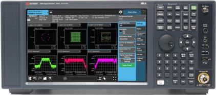
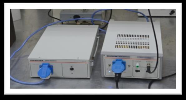
18 N6141A EMI Measurement Application Pre-compliance GW Instek low cost solution Compliance Keysight CXA entry-level Keysight MXE N9038A


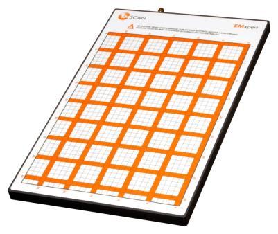
19 CXA EMC analyzer precompliance USB LAN/USB EMSCAN Scanner


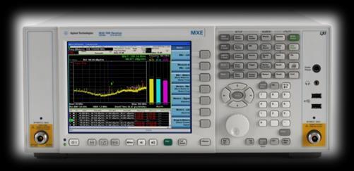
20 MXE EMI Reciever Excellent accuracy and sensitivity GHz GHz Full Cispr Compliance - -two inputs for conducted and radiated Real Time Analyzer - Up to 85 Mhz RTBW - Time Domain Scan Capability 20 Hz to 1 GHz surge protected 20 Hz to 3.5Ghz or 8.4Ghz or 26.5Ghz or 44GHz - Upgradable up to 44Ghz
21 Agenda Introduzione alle misure EMI Terminologia; precompliance verso full compliance Setup di misura: emissione radiate e condotte CISPR & MIL461F (Cenni) L analizzatore di spettro per le misure EMI Time Scan mode Differenti metodi di scansione ( swept, stepped, time domain ) Approccio veloce al precompliance Real Time Analysis Definizione di Real Time, Real Time operation, Overlap processing
 Test MORE devices Shorter turn-around-time Depends On: Scan type (Stepped, Swept, Time Domain) Resolution")
22 Customer challenge Need for SPEED DUTs that require short measurement time (ex. motor starter) Test MORE devices Shorter turn-around-time Depends On: Scan type (Stepped, Swept, Time Domain) Resolution Bandwidth Dwell Time RF Preselector Other?
23 Methods to EMI Scanning Stepped Scan Slowest method LO moves for every bin Must re-tune LO each time Swept Scan Slow (slightly faster than Stepped) LO re-tunes once each sweep Time Domain Scan (TDS) Very fast Highly overlapped FFT (>90%) Alternate scan method allowed by CISPR 16

24 Time Domain Scan (TDS) What is Time Domain Scan - A new way to do Frequency scanning - Swept scans, Stepped scans, now Time Domain scans FFT-based scan - uses ~ 90% overlap (in time) to ensure amplitude accuracy for measurements of both CW and Impulsive signals Allowed by CISPR 16, but not required. - Internal Automotive industry testing specifications require Time Domain 33
25 amplitude amplitude How Time Domain Sweep Saves Time Have to dwell at each RBW Only have to dwell for each FFT BW (multiple RBWs) FFT BW Receiver Resolution BW frequency Receiver FFT BW frequency Swept or Stepped Frequency Scan Time Domain Frequency Scan
26 Window Effects and Sample Rate Classic FFT is critically sampled windows are contiguous What happens to impulsive signals? Signals that fall between windows are attenuated by window edges Impulsive signals not detected or detected with amplitude scalloping How to solve this problem?

27 Oversampling before FFT Answer is to add overlap windowing Equivalent to increasing sampling rate out of the decimated downconverters Impulsive signals no longer can fall between widows Amplitude scalloping reduced More overlapping => less amplitude errors
28 Time Domain improves sweep time Time Domain Scan Frequency Domain Scan CISPR Band MXE MXE 30MHz 1GHz Peak det. 10ms. dwell RBW =120kHz 3 pts/rbw ~ 12 s 242 sec smooth scan 150kHz 30 MHz Peak det 100ms. dwell RBW = 9kHz 2 pts/rbw ~ 13 s 664 sec smooth scan Page 37
29 Agenda Introduzione alle misure EMI Terminologia; precompliance verso full compliance Setup di misura: emissione radiate e condotte CISPR & MIL461F (Cenni) L analizzatore di spettro per le misure EMI Time Scan mode Differenti metodi di scansione ( swept, stepped, time domain ) Approccio veloce al precompliance Real Time Analysis Definizione di Real Time, Real Time operation, Overlap processing
30 Customer Challenge Quickly detect and locate non-cooperative modern signals which may be intermittent, be of short duration, spread spectrum, have low power and/or low energy.
31 What is Real Time Analysis? General Definition of Real Time Measurement operations where all signal samples are used in calculating measurement results of some kind (usually spectrum) Real Time Bandwidth (RTBW) The widest analysis bandwidth where an analyzer can maintain real time operation Duration of maintaining real time operation is not specified; it may assumed to be short term or long term or unlimited Current Usage for Signal Analyzers A spectrum or FFT analyzer having a signal processing path where most or all samples, even at wide bandwidths, are used to create a spectral display or to trigger signal measurement or acquisition (sometimes both)


32 What is Real Time? Gap free no dead time between acquisitions; all sampled data is processed; process is continuous Consistent speed all hardware implementation of FFT spectrum generation not subject to Windows task interruptions

33 What is Real Time? High speed measurements many thousands of FFT generated spectrums per second, vastly exceeding software FFT speed High speed displays combine large numbers of measurements to form responsive, insight-producing displays
34 Real Time Operation In Real Time Operation the Analyzer s Processing (CALC) is Fast Enough to Keep Up with All Data Samples However some data may still be lost CALC Time Includes FFT or Power Spectrum, Averaging, Display Updates, etc.
35 Overlap Processing If Processing is Faster than Sampling, Perform Additional FFTs With Partially-New Time Records as Samples Come In Overlap 0% Overlap 50% Processor Idle Avoid Loss of Data Due to Windowing Window Function Accurate Amplitude Measurements of Short Duration Signals
36 Swept tuned spectrum analyzer Pros: - Excellent dynamic range - Very fast sweep for very large span - Precisely control sweep time - Easy to measure line spectrum of pulse signal Cons: - Could miss intermittent signal contents - Very slow when RBW:SPAN is too small - -
37 Snap shot FFT spectrum analyzer mixer attn filter IF A/D FFT LO Sample scheduler Pros: - Not missing signal content within information bandwidth - Very fast update at narrow RBW - Provides digital demodulation Cons: - Relative slow under very large bandwidth - Cannot precisely control sweep time - When signal is larger than its instantaneous bandwidth, stitching is required (could miss change of signals)
38 Real Time Spectrum Analyzer mixer attn filter IF A/D FFT LO Gap free sampling /buffering Pros: - Provide 100% POI to capture signal within real time bandwidth - Only way to measure transient and dynamic signals - IQ streaming - Ideal for RF pulse signal characterization Cons: - Real time bandwidth is limited - Typically it is less accurate comparing with GP SA


39 Probability of missing signals Freq Real time BW Time Swept tuned SA Snapshot FFT SA Real time SA
40


41 RTSA applications Embedded signal In traditional SA mode, it is hard to find the interfering signal buried inside downlink carrier. The narrow band signal (center: 877MHz, bandwidth:12 khz ) In RTSA, density display can clearly identify the embedded signal at 877MHz


42 RTSA Enhancements Available on Xseries Enabled in both FMT and Level Triggers Trigger only on signals that are less than, greater than, inside, or outside defined time durations Interfering Zigbee and WLAN - Overlapping signals in the frequency domain can be resolved by using TQT Isolated WLAN signal Isolated Zigbee


43 Summary 3.57 us Probability of Intercept Best performance for measuring intermittent signals Widest BW & Freq 85 MHz bandwidth and 44 GHz frequency range to analyze large chunks of the spectrum Two in one Eliminate the need for a specialized or dedicated instrument by adding real-time capabilities to the MXE EMI Reciever
44 Per documentazione su prodotti ed applicazioni EMI/EMC visitare il sito THANK YOU!!
Utilizzo del Time Domain per misure EMI
 Utilizzo del Time Domain per misure EMI Roberto Sacchi Measurement Expert Manager - Europe 7 Giugno 2017 Compliance EMI receiver requirements (CISPR 16-1-1 ) range 9 khz - 18 GHz: A normal +/- 2 db absolute
Understanding Probability of Intercept for Intermittent Signals
 2013 Understanding Probability of Intercept for Intermittent Signals Richard Overdorf & Rob Bordow Agilent Technologies Agenda Use Cases and Signals Time domain vs. Frequency Domain Probability of Intercept
EMC Back to Basics. Matthew Carter EMC Product Support Engineer Agilent Technologies Inc. April 16, 2014
 EMC Back to Basics Matthew Carter EMC Product Support Engineer Agilent Technologies Inc. April 16, 2014 Agilent Technologies, Inc. 2014 Agenda EMC Back to Basics Overview What is Electromagnetic Compatibility?
Misure di pre-compliance EMI
 Misure di pre-compliance EMI Roberto Sacchi Application Engineer Roberto_sacchi@agilent.com Page 1 Agenda Introduzione alle misure EMI Terminologia; Sistema di misura (antenna, LISN, ricevitore, etc.);
Keysight Technologies Essential Capabilities of EMI Receivers. Application Note
 Keysight Technologies Essential Capabilities of EMI Receivers Application Note Contents Introduction... 3 CISPR 16-1-1 Compliance... 3 MIL-STD-461 Compliance... 4 Important features not required by CISPR
The Value of Pre-Selection in EMC Testing. Scott Niemiec Application Engineer
 The Value of Pre-Selection in EMC Testing Scott Niemiec Application Engineer Video Demonstrating Benefit of Pre-selection 400MHz -1GHz Sweep with RBW = 120kHz Yellow: w/ preselection Green: w/o pre-selection
Essential Capabilities of EMI Receivers. Application Note
 Essential Capabilities of EMI Receivers Application Note Contents Introduction... 3 CISPR 16-1-1 Compliance... 3 MIL-STD-461 Compliance... 4 Important features not required by CISPR 16-1-1 or MIL-STD-461...
RF Fundamentals Part 2 Spectral Analysis
 Spectral Analysis Dec 8, 2016 Kevin Nguyen Keysight Technologies Agenda Overview Theory of Operation Traditional Spectrum Analyzers Modern Signal Analyzers Specifications Features Wrap-up Page 2 Overview
EMC Measurements. Jan Sjögren Electronic Measurements Group Agilent Technologies Page 1. EMC seminar
 EMC Measurements Jan Sjögren Electronic Measurements Group Agilent Technologies jan_sjogren@agilent.com Page 1 Day Agenda 8.45 REGISTRATION 9.00 Introduction 9.15 EMC Back to Basics EMC - What is it and
Introduction: The FFT emission measurement method
 Introduction: The FFT emission measurement method Tim Williams Elmac Services C o n s u l t a n c y a n d t r a i n i n g i n e l e c t r o m a g n e t i c c o m p a t i b i l i t y Wareham, Dorset, UK
Understanding RF and Microwave Analysis Basics
 Understanding RF and Microwave Analysis Basics Kimberly Cassacia Product Line Brand Manager Keysight Technologies Agenda µw Analysis Basics Page 2 RF Signal Analyzer Overview & Basic Settings Overview
PXIe Contents SPECIFICATIONS. 14 GHz and 26.5 GHz Vector Signal Analyzer
 SPECIFICATIONS PXIe-5668 14 GHz and 26.5 GHz Vector Signal Analyzer These specifications apply to the PXIe-5668 (14 GHz) Vector Signal Analyzer and the PXIe-5668 (26.5 GHz) Vector Signal Analyzer with
SEMINARI EMC VOLTA 2016 Ricevitori EMI per misure di prequalifica e full-compliance
 g SEMINARI EMC VOLTA 2016 Ricevitori EMI per misure di prequalifica e full-compliance o 7 Giugno 2016 Osimo (AN) o 8 Giugno 2016 Correggio (RE) o 9 Giugno 2016 Vicenza (VI) o 10 Giugno 2016 Burago Molgora
Advanced Test Equipment Rentals ATEC (2832)
") Established 1981 Advanced Test Equipment Rentals www.atecorp.com 800-404-ATEC (2832) R3000 EMI TEST RECEIVERS Fully IF digital EMI Receivers family for measurement of electromagnetic interference from
Established 1981 Advanced Test Equipment Rentals www.atecorp.com 800-404-ATEC (2832) R3000 EMI TEST RECEIVERS Fully IF digital EMI Receivers family for measurement of electromagnetic interference from
ER55 EMI TEST RECEIVER Family of automatic test receivers for measurement of electromagnetic interference from 9kHz to 1GHz
 ER55 EMI TEST RECEIVER Family of automatic test receivers for measurement of electromagnetic interference from 9kHz to 1GHz Compact designed and manufactured in compliance with CISPR 16-1, For Measurements
Analyze Agile or Elusive Signals Using Real-Time Measurement and Triggering Ben Zarlingo, Agilent Technologies Inc.
 Analyze Agile or Elusive Signals Using Real-Time Measurement and Triggering Ben Zarlingo, Agilent Technologies Inc. This Webcast Agile & Elusive Signals Discovering Signals vs. Troubleshooting, Optimizing
Interference Analysis and Spectrum Monitor Seminar
 Interference Analysis and Spectrum Monitor Seminar Handheld RF & Microwave Instruments Andrew Benn Business Development Manager Agilent Technologies Wednesday 12 th October 2011 1 Agilent Technologies,
3250 Series Spectrum Analyzer
 The most important thing we build is trust ADVANCED ELECTRONIC SOLUTIONS AVIATION SERVICES COMMUNICATIONS AND CONNECTIVITY MISSION SYSTEMS 3250 Series Spectrum Analyzer > Agenda Introduction
ER55 EMI TEST RECEIVER Family of automatic test receivers for measurement of electromagnetic interference from 9kHz to 2.8GHz.
 ER55 EMI TEST RECEIVER Family of automatic test receivers for measurement of electromagnetic interference from 9kHz to 2.8GHz. Compact designed and manufactured in compliance with CISPR 16-1-1 For Measurements
Real-Time Spectrum Analysis (RTSA) -Triggering, and Signal Capture/Playback for Agile and Elusive Signals. Keysight Technologies
 -Triggering, and Signal Capture/Playback for Agile and Elusive Signals. Keysight Technologies") Real-Time Spectrum Analysis (RTSA) -Triggering, and Signal Capture/Playback for Agile and Elusive Signals Keysight Technologies A brief history of Keysight Technologies 1939 1998: Hewlett-Packard years
Real-Time Spectrum Analysis (RTSA) -Triggering, and Signal Capture/Playback for Agile and Elusive Signals Keysight Technologies A brief history of Keysight Technologies 1939 1998: Hewlett-Packard years
Techniques for Characterizing Spurious Signals
 Techniques for Characterizing Spurious Signals October 21, 2014 Riadh Said Product Manager Microwave and Communications Division Keysight Technologies Our Goals today Review the sweep time equation to
Timing Considerations Using FFT-based Measuring Receivers for EMI Compliance Measurements
 Timing Considerations Using FFT-based Measuring Receivers for EMI Compliance Measurements Jens Medler Rohde & Schwarz GmbH & Co. KG Abstract The use of FFT-based measuring receivers for EMI compliance
Understanding New Pulse-analysis Techniques
 Understanding New Pulse-analysis Techniques Giuseppe Savoia Keysight Technologies Aerospace Defense Symposium Agenda Concept for Radar/Pulse signal analysis AD Symposium Page 2 Vector signal analyzers
GET10B Radar Measurement Basics- Spectrum Analysis of Pulsed Signals. Copyright 2001 Agilent Technologies, Inc.
 GET10B Radar Measurement Basics- Spectrum Analysis of Pulsed Signals Copyright 2001 Agilent Technologies, Inc. Agenda: Power Measurements Module #1: Introduction Module #2: Power Measurements Module #3:
Analyze Agile or Elusive Signals Using Real-time Measurement and Triggering. Aerospace & Defense Symposium 2013 Agilent Technologies
 Analyze Agile or Elusive Signals Using Real-time Measurement and Triggering This Presentation Agile & Elusive Signals Discovering Signals vs. Troubleshooting, Optimizing Case Studies Dynamic signal environment-ism
Measurement of Digital Transmission Systems Operating under Section March 23, 2005
 Measurement of Digital Transmission Systems Operating under Section 15.247 March 23, 2005 Section 15.403(f) Digital Modulation Digital modulation is required for Digital Transmission Systems (DTS). Digital
Radiated Spurious Emission Testing. Jari Vikstedt
 Radiated Spurious Emission Testing Jari Vikstedt jari.vikstedt@ets-lindgren.com What is RSE? RSE = radiated spurious emission Radiated chamber Emission EMI Spurious intentional radiator 2 Spurious Spurious,
Advances in RF and Microwave Measurement Technology
 1 Advances in RF and Microwave Measurement Technology Chi Xu Certified LabVIEW Architect Certified TestStand Architect New Demands in Modern RF and Microwave Test In semiconductor and wireless, technologies
Debugging EMI Using a Digital Oscilloscope. Dave Rishavy Product Manager - Oscilloscopes
 Debugging EMI Using a Digital Oscilloscope Dave Rishavy Product Manager - Oscilloscopes 06/2009 Nov 2010 Fundamentals Scope Seminar of DSOs Signal Fidelity 1 1 1 Debugging EMI Using a Digital Oscilloscope
Contents. CALIBRATION PROCEDURE NI PXIe GHz and 14 GHz RF Vector Signal Analyzer
 CALIBRATION PROCEDURE NI PXIe-5665 3.6 GHz and 14 GHz RF Vector Signal Analyzer This document contains the verification procedures for the National Instruments PXIe-5665 (NI 5665) RF vector signal analyzer
Appnote - Realtime Spectrum Analyzer vs Spectrum Analyzer
 Appnote - Realtime Spectrum Analyzer vs Spectrum Analyzer Today the RF industry has to face more and more the open question, how to transport the data from my test device (DUT) to different receiver spots
Keysight Technologies N6141A & W6141A EMI X-Series Measurement Application. Technical Overview
 Keysight Technologies N6141A & W6141A EMI X-Series Measurement Application Technical Overview EMI Measurement Application To avoid costly delays that can result from failed compliance testing, Keysight's
Rohde & Schwarz EMI/EMC debugging with modern oscilloscope. Ing. Leonardo Nanetti Rohde&Schwarz
 Rohde & Schwarz EMI/EMC debugging with modern oscilloscope Ing. Leonardo Nanetti Rohde&Schwarz EMI debugging Agenda l The basics l l l l The idea of EMI debugging How is it done? Application example What
Spectrum Analyzers 2680 Series Features & benefits
 Data Sheet Features & benefits n Frequency range: 9 khz to 2.1 or 3.2 GHz n High Sensitivity -161 dbm/hz displayed average noise level (DANL) n Low phase noise of -98 dbc/hz @ 10 khz offset n Low level
Advanced Test Equipment Rentals ATEC (2832)
") Established 1981 Advanced Test Equipment Rentals www.atecorp.com 800-404-ATEC (2832) EMI Testing According to CSPR Publication 16 Recommendations Combining the 85685A RF preselector with the 8566B or 8568B
Established 1981 Advanced Test Equipment Rentals www.atecorp.com 800-404-ATEC (2832) EMI Testing According to CSPR Publication 16 Recommendations Combining the 85685A RF preselector with the 8566B or 8568B
FFT 3010 EMI TEST RECEIVER
 FFT 3010 EMI TEST RECEIVER Fully FFT digital EMI Receiver for measurement of conducted electromagnetic interference from 9kHz to 30MHz Compact designed and manufactured compliant to CISPR 16 International
Advances in RF and Microwave Measurement Technology
 1 Advances in RF and Microwave Measurement Technology Rejwan Ali Marketing Engineer NI Africa and Oceania New Demands in Modern RF and Microwave Test In semiconductor and wireless, technologies such as
8 Hints for Better Spectrum Analysis. Application Note
 8 Hints for Better Spectrum Analysis Application Note 1286-1 The Spectrum Analyzer The spectrum analyzer, like an oscilloscope, is a basic tool used for observing signals. Where the oscilloscope provides
EMI Test Receivers: Past, Present and Future
 EM Test Receivers: Past, Present and Future Andy Coombes EMC Product Manager Rohde & Schwarz UK Ltd 9 th November 2016 ntroduction ı Andy Coombes EMC Product Manager ı 20 years experience in the field
8 Hints for Better Spectrum Analysis. Application Note
 8 Hints for Better Spectrum Analysis Application Note 1286-1 The Spectrum Analyzer The spectrum analyzer, like an oscilloscope, is a basic tool used for observing signals. Where the oscilloscope provides
Keysight Technologies PNA-X Series Microwave Network Analyzers
 Keysight Technologies PNA-X Series Microwave Network Analyzers Active-Device Characterization in Pulsed Operation Using the PNA-X Application Note Introduction Vector network analyzers (VNA) are the common
Spectrum Analyzer Training
 Spectrum Analyzer Training Roberto Sacchi Application Engineer roberto_sacchi@agilent.com Page 1 Agenda Introduction Overview: What is Signal Analysis? What Measurements are available? Theory of Operation
Federal Communications Commission Office of Engineering and Technology Laboratory Division
 April 9, 2013 Federal Communications Commission Office of Engineering and Technology Laboratory Division Guidance for Performing Compliance Measurements on Digital Transmission Systems (DTS) Operating
Introduction. In the frequency domain, complex signals are separated into their frequency components, and the level at each frequency is displayed
 SPECTRUM ANALYZER Introduction A spectrum analyzer measures the amplitude of an input signal versus frequency within the full frequency range of the instrument The spectrum analyzer is to the frequency
Keysight Technologies N9320B RF Spectrum Analyzer
 Keysight Technologies N9320B RF Spectrum Analyzer 9 khz to 3.0 GHz Data Sheet Definitions and Conditions The spectrum analyzer will meet its specifications when: It is within its calibration cycle It has
Definizione. Tipi di analizzatori
 Corso di Laboratorio di misure ad alta frequenza Definizione Introduzione all analizzatore di spettro: principio di funzionamento e principali applicazioni Docenti: Andrea Mostacci; Alessandra Paffi andrea.mostacci@uniroma1.it;
Ave output power ANT 1(dBm) Ave output power ANT 2 (dbm)
 Ave output power ANT 2 (dbm)") Page 41 of 103 9.6. Test Result The test was performed with 802.11b Channel Frequency (MHz) power ANT 1(dBm) power ANT 2 (dbm) power ANT 1(mW) power ANT 2 (mw) Limits dbm / W Low 2412 7.20 7.37 5.248 5.458
Page 41 of 103 9.6. Test Result The test was performed with 802.11b Channel Frequency (MHz) power ANT 1(dBm) power ANT 2 (dbm) power ANT 1(mW) power ANT 2 (mw) Limits dbm / W Low 2412 7.20 7.37 5.248 5.458
Data Sheet SC5317 & SC5318A. 6 GHz to 26.5 GHz RF Downconverter SignalCore, Inc. All Rights Reserved
 Data Sheet SC5317 & SC5318A 6 GHz to 26.5 GHz RF Downconverter www.signalcore.com 2018 SignalCore, Inc. All Rights Reserved Definition of Terms 1 Table of Contents 1. Definition of Terms... 2 2. Description...
R&S FSWP Phase Noise Analyzer Specifications
 R&S FSWP Phase Noise Analyzer Specifications Data Sheet Version 06.00 CONTENTS Definitions... 4 Specifications... 5 Frequency... 5 Phase noise measurements... 5 Phase noise sensitivity with R&S FSWP-B61
PXIe Contents CALIBRATION PROCEDURE. Reconfigurable 6 GHz RF Vector Signal Transceiver with 200 MHz Bandwidth
 IBRATION PROCEDURE PXIe-5646 Reconfigurable 6 GHz Vector Signal Transceiver with 200 MHz Bandwidth This document contains the verification and adjustment procedures for the PXIe-5646 vector signal transceiver.
DSA-815 Demo Guide. Solution: The DSA 800 series of spectrum analyzers are packed with features.
 FAQ Instrument Solution FAQ Solution Title DSA-815 Demo Guide Date:08.29.2012 Solution: The DSA 800 series of spectrum analyzers are packed with features. Spectrum analyzers are similar to oscilloscopes..
SIR-4011 MICROWAVE WIDEBAND DSP RECEIVER. WIDE FREQUENCY RANGE: GHz
 SIR-4011 MICROWAVE WIDEBAND DSP RECEIVER WIDE FREQUENCY RANGE: 0.5 18.0 GHz FEATURES Advanced Front Panel Graphics Display High Dynamic Range: In band Input IP3 > 0 dbm, NF< 15 db DSP Based AM, FM Video
OPEN TEM CELLS FOR EMC PRE-COMPLIANCE TESTING
 1 Introduction Radiated emission tests are typically carried out in anechoic chambers, using antennas to pick up the radiated signals. Due to bandwidth limitations, several antennas are required to cover
Reconfigurable 6 GHz RF Vector Signal Transceiver with 1 GHz Bandwidth
 CALIBRATION PROCEDURE PXIe-5840 Reconfigurable 6 GHz RF Vector Signal Transceiver with 1 GHz Bandwidth This document contains the verification procedures for the PXIe-5840 vector signal transceiver. Refer
Specification for Conducted Emission Test
 1 of 10 1. EMI Receiver Frequency range 9kHz 7.0 GHz Measurement time per frequency 10 µs to 100 s time sweep, span = 0 Hz - 1 µs to 16000 s Sweep time in steps of 5 % frequency sweep, span 10 Hz - 2.5
SC5407A/SC5408A 100 khz to 6 GHz RF Upconverter. Datasheet. Rev SignalCore, Inc.
 SC5407A/SC5408A 100 khz to 6 GHz RF Upconverter Datasheet Rev 1.2 2017 SignalCore, Inc. support@signalcore.com P R O D U C T S P E C I F I C A T I O N S Definition of Terms The following terms are used
SC5307A/SC5308A 100 khz to 6 GHz RF Downconverter. Datasheet SignalCore, Inc.
 SC5307A/SC5308A 100 khz to 6 GHz RF Downconverter Datasheet 2017 SignalCore, Inc. support@signalcore.com P RODUCT S PECIFICATIONS Definition of Terms The following terms are used throughout this datasheet
Signal Detection with EM1 Receivers
 Signal Detection with EM1 Receivers Werner Schaefer Hewlett-Packard Company Santa Rosa Systems Division 1400 Fountaingrove Parkway Santa Rosa, CA 95403-1799, USA Abstract - Certain EM1 receiver settings,
ESA-E Series Spectrum Analyzer
 ESA-E Series Spectrum Analyzer Data Sheet Available frequency ranges: E4402B 9 khz to 3.0 GHz E4404B 9 khz to 6.7 GHz E4405B 9 khz to 13.2 GHz E4407B 9 khz to 26.5 GHz Table of Contents Definitions of
Wide bandwidth measurements and Calibration
 Wide bandwidth measurements and Calibration Agenda Wide bandwidth measurement definitions The need for wide bandwidth measurements Types of wide bandwidth measurements Accurate measurements and system
An Introduction to FFT EMI Receivers
 An Introduction to FFT EMI Receivers Introduction An evolution in EMI receiver design is underway to take advantage of today s digital signal processing (DSP) technologies, using fast Fourier transform
Agilent CSA Spectrum Analyzer
 Agilent CSA Spectrum Analyzer N1996A Exceptional performance... anytime, anywhere Frequency coverage Frequency range: 100 khz to 3 or 6 GHz Signal source: 10 MHz to 3 or 6 GHz Preamplifier to 3 or 6 GHz
7. Transmitter Radiated Spurious Emissions and Conducted Spurious Emission
 7. Transmitter Radiated Spurious Emissions and Conducted Spurious Emission 7.1 Test Setup Refer to the APPENDIX I. 7.2 Limit According to 15.247(d), in any 100 khz bandwidth outside the frequency band
Agilent N9320B RF Spectrum Analyzer
 Agilent N9320B RF Spectrum Analyzer 9 khz to 3.0 GHz Data Sheet Definitions and Conditions The spectrum analyzer will meet its specifications when: It is within its calibration cycle It has been turned
Demo / Application Guide for DSA815(-TG) / DSA1000 Series
 / DSA1000 Series") Demo / Application Guide for DSA815(-TG) / DSA1000 Series TX1000 Mobile Phone Frontend Mixer Bandpass Filter PA The schematic above shows a typical front end of a mobile phone. Our TX1000 RF Demo Kit shows
Demo / Application Guide for DSA815(-TG) / DSA1000 Series TX1000 Mobile Phone Frontend Mixer Bandpass Filter PA The schematic above shows a typical front end of a mobile phone. Our TX1000 RF Demo Kit shows
OPEN TEM CELLS FOR EMC PRE-COMPLIANCE TESTING
 1 Introduction Radiated emission tests are typically carried out in anechoic chambers, using antennas to pick up the radiated signals. Due to bandwidth limitations, several antennas are required to cover
Title: Test on 5.8 GHz Band Outdoor WiFi (802.11b/g) Wireless Base Station
 Wireless Base Station") Page 20 of 51 Pages 7.5. Conducted spurious emission 7.5.1. Requirements: Clause 15.247(d). In any 100 khz bandwidth outside the frequency band in which the spread spectrum or digitally modulated intentional
Page 20 of 51 Pages 7.5. Conducted spurious emission 7.5.1. Requirements: Clause 15.247(d). In any 100 khz bandwidth outside the frequency band in which the spread spectrum or digitally modulated intentional
SC5306B 1 MHz to 3.9 GHz RF Downconverter Core Module. Datasheet SignalCore, Inc.
 SC5306B 1 MHz to 3.9 GHz RF Downconverter Core Module Datasheet 2015 SignalCore, Inc. support@signalcore.com SC5306B S PECIFICATIONS Definition of Terms The following terms are used throughout this datasheet
Keysight X-Series Signal Analyzers
 Keysight X-Series Signal Analyzers This manual provides documentation for the following Analyzer: N9040B UXA Signal Analyzer UXA Specification Guide (Comprehensive Reference Data) Notices Keysight Technologies,
EXHIBIT 7: MEASUREMENT PROCEDURES Pursuant 47 CFR 2.947
 EXHIBIT 7: MEASUREMENT PROCEDURES Pursuant 47 CFR 2.947 7.1 RF Power -- Pursuant to 47 CFR 2.947(c) Method of Conducted Output Power Measurement: Adaptation of TIA/EIA-603-A clause 2.2.1 for Pulsed Measurements
Keysight Technologies 8 Hints for Making Better Measurements Using RF Signal Generators. Application Note
 Keysight Technologies 8 Hints for Making Better Measurements Using RF Signal Generators Application Note 02 Keysight 8 Hints for Making Better Measurements Using RF Signal Generators - Application Note
CXA X-Series Signal Analyzer, Multi-touch N9000B
 DATA SHEET CXA X-Series Signal Analyzer, Multi-touch N9000B 9 khz to 3.0, 7.5, 13.6, or 26.5 GHz Table of Contents Definitions and Conditions...3 Frequency and Time Specifications...4 Amplitude Accuracy
2015 Interference 101. Robin Jackman Application Engineer
 2015 Interference 101 Robin Jackman Application Engineer Agenda What is Interference Introduction Definitions Spectrum Analyzer Concepts Concepts, Controls, Displays Making good measurements Measuring
Keysight N9038A MXE EMI Receiver
 Keysight N9038A MXE EMI Receiver 3 Hz up to 44 GHz frequency range Compliant with CISPR 16-1-1:2010 and MIL-STD-461 ± 0.5 db at 1 GHz amplitude accuracy 166 dbm at 1 GHz DANL with Noise Floor Extension
Keysight Technologies Enhance EMC Testing with Digital IF. Application Note
 Keysight Technologies Enhance EMC Testing with Digital IF Application Note Introduction With today s accelerating business environment and development cycles, EMC measurement facilities that offer rapid
EMI 相容性測試 預相容性測試及量測法規
 EMI 相容性測試 預相容性測試及量測法規 12/13/2016 太克科技 Laurance Yeh 葉志豪 chi-hao.yeh@tektronix.com Agenda EMI introduction EMI pre-compliance and debugging tools RSA306B demo MDO4000C demo lab 13 December 2016 Agenda EMI
Keysight X-Series Signal Analyzers
 Keysight X-Series Signal Analyzers This manual provides documentation for the following Analyzer: N9010B EXA Signal Analyzer EXA Specification Guide (Comprehensive Reference Data) Notices Keysight Technologies,
Understanding Spectrum Analysis
 Understanding Spectrum Analysis Swept, FFT, and RTSA principles E & T Team September 2017 Operation principles of SPA architectures Agenda Part I Chasing dynamic and transient signals Probability of intercept
ACCORDING TO: FCC part 15 subpart C, and subpart B FOR:
 Electrical Hermon Laboratories Ltd. P.O.Box 23, Binyamina 30500, Israel Tel. +972 4628 8001 Fax. +972 4628 8277 E-mail: mail@hermonlabs.com TEST REPORT ACCORDING TO: FCC part 15 subpart C, 15.247 and subpart
Introducing the Keysight RF PXIe Vector Signal Analyzer & Generator M9391A & M9381A. Updated: August 2015
 Introducing the Keysight RF PXIe Vector Signal Analyzer & Generator M9391A & M9381A Updated: August 2015 Agenda Page 2 M9391A PXIe vector signal generator M9381A PXIe vector signal analyzer M9380A PXIe
Contents. CALIBRATION PROCEDURE NI PXIe-5668R 14 GHz and 26.5 GHz Signal Analyzer
 CALIBRATION PROCEDURE NI PXIe-5668R 14 GHz and 26.5 GHz Signal Analyzer This document contains the verification procedures for the National Instruments PXIe-5668R (NI 5668R) vector signal analyzer (VSA)
DSA700 Series Spectrum Analyzer
 DSA700 Series Spectrum Analyzer Product Features: All-Digital IF Technology Frequency Range from 100 khz up to 1 GHz Min. -155 dbm Displayed Average Noise Level (Typ.) Min.
100 Hz to 22. HP 8566B Spectrum Analyzer. Discontinued Product Support Information Only. Outstanding Precision and Capability
 Discontinued Product Support Information Only This literature was published years prior to the establishment of Agilent Technologies as a company independent from Hewlett-Packard and describes products
EMC / Field strength Signal generation and analysis
 EMC / Field strength Signal generation and analysis 48 Uncovers every disturbance Standard-compliant EMI test receivers must meet very high requirements with respect to their RF characteristics. Not only
DSA800. No.1 RIGOL TECHNOLOGIES, INC.
 No.1 DSA800 9 khz to 1.5 GHz Frequency Range Typical -135 dbm Displayed Average Noise Level (DANL) -80 dbc/hz @10 khz offset Phase Noise Total Amplitude Uncertainty
FCC and ETSI Requirements for Short-Range UHF ASK- Modulated Transmitters
 From December 2005 High Frequency Electronics Copyright 2005 Summit Technical Media FCC and ETSI Requirements for Short-Range UHF ASK- Modulated Transmitters By Larry Burgess Maxim Integrated Products
R3477. Ideal for mobile communication applications including base stations and handsets, from the development stage to production and installation
 R3477 Signal Analyzers Ideal for mobile communication applications including base stations and handsets, from the development stage to production and installation Frequency range: 9 khz to 13.5 GHz World
Agilent 8560 E-Series Spectrum Analyzers
 Agilent 8560 E-Series Spectrum Analyzers Data Sheet 8560E 30 Hz to 2.9 GHz 8561E 30 Hz to 6.5 GHz 8562E 30 Hz to 13.2 GHz 8563E 30 Hz to 26.5 GHz 8564E 30 Hz to 40 GHz 8565E 30 Hz to 50 GHz 8565E SPECTRUM
ThinkRF R5500. Real-Time Spectrum Analyzer. 9 khz to 8 GHz / 18 GHz / 27 GHz. Product Brochure and Technical Datasheet. Featuring
 Product Brochure and Technical Datasheet ThinkRF R5500 Real-Time Spectrum Analyzer 9 khz to 8 GHz / 18 GHz / 27 GHz Featuring Real-Time Bandwidth (RTBW) up to 100 MHz Spurious Free Dynamic Range (SFDR)
PN9000 PULSED CARRIER MEASUREMENTS
 The specialist of Phase noise Measurements PN9000 PULSED CARRIER MEASUREMENTS Carrier frequency: 2.7 GHz - PRF: 5 khz Duty cycle: 1% Page 1 / 12 Introduction When measuring a pulse modulated signal the
Agilent 8560 EC Series Spectrum Analyzers Data Sheet
 Agilent 8560 EC Series Spectrum Analyzers Data Sheet Agilent 8560EC 30 Hz to 2.9 GHz Agilent 8561EC 30 Hz to 6.5 GHz 1 Agilent 8562EC 30 Hz to 13.2 GHz Agilent 8563EC 30 Hz to 26.5 GHz Agilent 8564EC 30
Agilent Technologies PSA Series Spectrum Analyzers Test and Adjustment Software
 Test System Overview Agilent Technologies PSA Series Spectrum Analyzers Test and Adjustment Software Test System Overview The Agilent Technologies test system is designed to verify the performance of the
Keysight Technologies Understanding and Applying Probability of Intercept in Real-time Spectrum Analysis. Application Note
 Keysight Technologies Understanding and Applying Probability of Intercept in Real-time Spectrum Analysis Application Note Introduction As today s wireless signals become more complex, the process of analyzing
On site RF troubleshooting for installation and maintenance
 On site RF troubleshooting for installation and maintenance Measure of interferers, high power for microwave links or low power for Base Stations uplink Troubleshooting of cables, or waveguides, and antennas
Agilent Back to Basics. Spectrum Analysis Back to Basics. Presented by: Michel Joussemet
 Agilent Back to Basics Spectrum Analysis Back to Basics Presented by: Michel Joussemet Aerospace and Defense Symposium 2007 EuMw 2007 Agilent Workshop Agenda Introduction Overview: What is Signal Analysis?
FCC PART 80 & 90 TEST REPORT
 849 NW STATE ROAD 45 NEWBERRY, FL 32669 USA PH: 888.472.2424 OR 352.472.5500 FAX: 352.472.2030 EMAIL: INFO@TIMCOENGR.COM HTTP://WWW.TIMCOENGR.COM FCC PART 80 & 90 TEST REPORT APPLICANT FCC ID MODEL NUMBER
ETSI Standards and the Measurement of RF Conducted Output Power of Wi-Fi ac Signals
 ETSI Standards and the Measurement of RF Conducted Output Power of Wi-Fi 802.11ac Signals Introduction The European Telecommunications Standards Institute (ETSI) have recently introduced a revised set
Spectrum Analyzer. EMI Receiver
 Challenges in Testing by Werner Schaefer Narrowband and Broadband Discrimination with a Spectrum Analyzer or EMI Receiver photo provided by Agilent 26 Conformity December 2007 In the field of EMC, the
Today s wireless. Best Practices for Making Accurate WiMAX Channel- Power Measurements. WiMAX MEASUREMENTS. fundamental information
 From August 2008 High Frequency Electronics Copyright Summit Technical Media, LLC Best Practices for Making Accurate WiMAX Channel- Power Measurements By David Huynh and Bob Nelson Agilent Technologies
NATIONAL TELECOMMUNICATION AGENCY
 NATIONAL TELECOMMUNICATION AGENCY ACT No. 1135 OF FEBRUARY 18, 2013 THE SUPERINTENDENT OF RADIOFREQUENCY AND SUPERVISION OF THE NATIONAL TELECOMMUNICATIONS AGENCY - ANATEL, in exercise of the powers conferred