SEMINARI EMC VOLTA 2016 Ricevitori EMI per misure di prequalifica e full-compliance
|
|
|
- Marjorie McDowell
- 5 years ago
- Views:
Transcription
 o 8 Giugno 2016 Correggio (RE)")

1 g SEMINARI EMC VOLTA 2016 Ricevitori EMI per misure di prequalifica e full-compliance o 7 Giugno 2016 Osimo (AN) o 8 Giugno 2016 Correggio (RE) o 9 Giugno 2016 Vicenza (VI) o 10 Giugno 2016 Burago Molgora (MI) relatori: Dott Mirko Bombelli Microlease Italia. Ing Angelo Cereser Microlease Italia.
2 Agenda Breve Introduzione alle misure EMI Setup di misura: emissione radiate e condotte CISPR & MIL461F (Cenni) L analisi spettrale per le misure EMI Circuiteria analogica verso nuove tecniche digitali Considerazioni su campo dinamico di misura e piano di rumore Problematiche di Misura Tecniche di scansione diverse ( step, swept, FFT ) Tempi di scansione ed sensibilita : trade-off Preselezione ed overload : trade-off Soluzioni Agilent Introduzione al nuovo ricevitore EMI Full Compliance Agilent MXE Uso degli analizzatori Agilent della Serie-X per misure EMI pre-compliance
 Conducted Transducers Measurement SW Open Sites (FF and NF) Anechoic Chambers Semi-Anechoic Chambers TEM cells")
3 transducer Measurement Equipment EMISSIONS Radiated Emissions Conducted Emissions EUT EUT Mains Equipment Compliance Receivers Spectrum Analyzers Preamps/Antennas EMSCAN tablets Towers/Turntables Control SW Artificial Mains Networks LISN - (line impedance stabilization network) Conducted Transducers Measurement SW Open Sites (FF and NF) Anechoic Chambers Semi-Anechoic Chambers TEM cells Reverberation chambers EMC Back to Basics 2014
4 transducer ESD source IMMUNITY Radiated Immunity Conducted Immunity ~ ~ EUT EUT AMN transducer RF Sources Power meters Power amps Antennas Measurement SW Control SW Equipment LISN Coupling Transducers - clamps, etc. ESD sources Screen rooms TEM cells GTEM cells EMC Back to Basics 2014
5 Pre-compliance vs. Full compliance Misure di Pre-Compliance measurements Valutazione delle emissioni condotte e radiate di un dispositivo utilizzando detectors, RBW e bande di analisi opportune, prima di andare in test house per le misure di Conformita. Misure di Full Compliance I test di Conformita richiedono Ricevitori che rispettino TUTTE le specifiche richieste dalla pubblicazione tecnica CISPR16-1-1, una area di test qualificata con torre di antenna e tavolo rotante per la massimizzazione dei segnali di interesse.


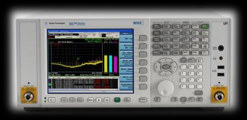
6 Misure di Pre Qualifica - Stima Unofficial delle performance del DUT prima del Full Compliance test - Tipicamente fatta con un SA negli ambienti aziendali disponibili. - Lo scopo e quello di minimizzare il rischio di Fail nelle successive misure in Test House. Misure di Full Compliance Xseries EMC analyzers, Field Fox, HSA - Test di Pass/Fail in accordo alle Norme - Richiede equippaggiamenti specifici e siti adatti - must comply to specific Mil or Comm l standards - Costose e time consuming Ricevitore MXE EMC Back to Basics 2014

7 EMI measurement system Set Up di misura emissioni radiate
8 Set Up di misura emissioni condotte
9 Tipiche funzionalita di un EMI Receiver CISPR nella banda di Compliance frequenze 9 khz EMI - 18 GHz: receiver requirements A normal +/- 2 db absolute accuracy CISPR-specified resolution bandwidths (-6 db) Peak, quasi-peak, EMI average, and RMS average detectors Specified input impedance with a nominal value of 50 ohms; deviations specified as VSWR Be able to pass product immunity in a 3 V/m field Be able to pass the CISPR pulse test (implies pre-selector below 1 GHz) Other specific harmonic and intermodulation requirements
10 Receiver requirements above 1 GHz Tipiche funzionalita di un EMI Reciever nella banda di frequenze sopra 1Ghz 1 MHz bandwidth for measurements No quasi-peak detector No CISPR pulse test, meaning no additional pre-selector required excellent sensitivity According to current FCC regulations, the maximum test frequency is the fifth harmonic of the highest clock frequency for an unintentional radiator (for example, computers without wireless connectivity) and the tenth harmonic for an intentional radiator (such as a cellular phone or wireless LAN).
11 MIL STD 461F MIL STD 461F Spectrum Analyzer use allowed (and commonly used) - need to ensure measurement linearity (avoid overloads) - need to have sufficient sensitivity (may need preamp) Requires MIL Bandwidths Requires Peak Detector +/- 2dB amp accuracy, +/- 2% frequency accuracy Dwell times specified in document
12 CISPR Product Group CISPR 11 - Industrial, Scientific, and Medical (ISM) Radio-Frequency Equipment CISPR 12 - Vehicles, Motorboats, and Spark-Ignited Engine-Driven Devices CISPR 13 - Sound and Television Broadcast Receivers and Associated Equipment CISPR 14 - Household Appliances, Electric Tools, and Similar Apparatus CISPR 15 - Electrical Lighting and Similar Equipment. CISPR 17 - Suppression Characteristics of Passive Radio Interference Filters and Components. Suppression CISPR 18 - Overhead Power Lines and High-Voltage Equipment CISPR 20 - Sound and Television Broadcast Receivers and Associated Equipment CISPR 21 - Interference to Mobile Radio communications CISPR 22 - Information Technology Equipment Radio Disturbance Characteristics CISPR 24 - Information Technology Equipment Immunity Characteristics CISPR 25 - Receivers Used on Board Vehicles, Boats, and on CISPR 32 Multimedia devices emission testing (under development) CISPR 35 Multimedia devices immunity testing (under development) EMC Back to Basics 2014
13 Swept Spectrum Analyzer Block Diagram Theory of Operation RF input attenuator mixer IF gain IF filter (RBW) envelope detector Input signal Pre-Selector Or Low Pass Input Filter local oscillator Log Amp video filter sweep generator Crystal Reference Oscillator ADC, Display & Video Processing
14 Traditional Spectrum Analyzer ( add scalar analysis with TG) Digitizing the video signal Product detector loss of phase information Classic superheterodyne swept spectrum analyzer
15 All Digital IF Advantages RF Section ADC FFT IF/BB Section on ASIC Flexibility: RBW filtering in 10% steps Filters with better selectivity Multiple operation modes (Swept, FFT, VSA, NFA) Accuracy: Log conversion practically ideal No drift errors; increased repeatability Speed: When Swept mode is slow, go FFT
16 Modern Spectrum Analyzer Block Diagram Modern Spectrum Analyzer Block Diagram Pre-amp Analog IF Filter Digital IF Filter FFT Digital Detectors Attenuation YIG ADC Swept vs. FFT Digital Log Amp Replaced by
 Level")
17 Input Connector RF Input Attenuator 2 db Steps Pre-selector Componenti che contribuiscono alla incertezza di misura Downconversion ADC DSP Input connector (mismatch) Calibrator RF input attenuator flatness and switching Mixer and input filter frequency response Frequency Dependent Frequency Independent Digital IF improves Amplitude Accuracy: Ref Level switching uncertainty (IF gain) Level correction digitally synthesized RBW filter switching uncertainty RBWs all digitally synthesized Display scale fidelity (Log Amp) Log response & display scaling digitally synthesized IF Filter IF Gain Log Amp Video Filter Log ADC

18 Input Connector RF Input Attenuator 2 db Steps Pre-selector Componenti che contribuiscono alla incertezza di misura Downconversion ADC DSP Amplitude Uncertainty Input connector (mismatch) Ref Level Switching Calibrator N9038A Receiver 0dB RF input attenuator RBW flatness and +/- Switching switching.05db <= +/-.5dB Mixer and input filter Frequency Dependent Analog IF (older receivers) <= +/- 1dB Display Scale +/-.15dB <= +/-.85dB Fidelity frequency response Frequency Independent Digital IF improves Amplitude Accuracy: Ref Level switching uncertainty (IF gain) Level correction digitally synthesized RBW filter switching uncertainty RBWs all digitally synthesized Display scale fidelity (Log Amp) Log response & display scaling digitally synthesized IF Filter IF Gain Log Amp Video Filter Log ADC
19 EMI Reciever Block DiagramrBlock Diagram Input 2 Pre-amp Transient Limiter Input 1 Attenuation RF Preselector Digital IF Filter Digital Detectors MXE Analog IF Filter FFT Swept vs. FFT Digital Log Amp ADC

20 Purpose of RF pre-selection RF Help Pre-selection to prevent overload by reducing (RF total input energy at input filtering) mixer RF preselector tracks the center frequency of the EMI receiver The bandwidth of the RF preselector is wider than the widest RBW used Useful in measuring broadband signals Types of filters used in RF pre-selectors Low-pass, Band-pass and High-pass Fixed and Tracking Narrow band signals Broadband signals

21 Detectors: Convert IF Samples to Display Bins or Multiple simultaneous detectors Buckets Peak, Neg Peak, Sample Display points or buckets Peak Normal, Average, Neg Peak Volts Sample Neg Peak Screen Shot Detector 3types Time P a
22 Detectors Most radiated and conducted limits are based on quasi-peak detection mode. P a
23 V Peak Detection Quasi-Peak Detection Average Detection time V Peak Detection time Quasi-Peak Detection Average Detection P a
24 Peak Detector QP Average Initially used QP Faster than QP and Average modes If all signals fall below the limit, then the product passes and no future testing is needed. For CW signal, Peak = QP Much slower by 2 or 3 order magnitude compared to using Peak detector Charge rate much faster than discharge rate Average the higher repetition rate of the signal, the higher QP reading Radiated emissions measurements above 1 GHz are performed using average detection
25 Some important concepts for EMI measurements: for EMI Sensitivity Amplitude Accuracy Scan Speed Others.

26 Specifications: Sensitivity/DANL Sensitivity is the Smallest Signal That Can Be Measured Signal Equals Noise 2.2 db
27 Specifications: Sensitivity/DANL Effective Level of Displayed Noise is a Function of RF Input Attenuation signal level 10 db Attenuation = 10 db Attenuation = 20 db Signal To Noise Ratio Decreases as RF Input Attenuation is Increased
28 Sensitivity/DANL: IF Filter (RBW) Displayed Noise is a Function of IF Filter Bandwidth 100 khz RBW 10 db 10 db 10 khz RBW 1 khz RBW Decreased BW = Decreased Noise
29 Techniques for Reducing DANL, Improving Dynamic Range and Amplitude Accuracy for Reducing DANL, Improving Dynamic Range and Amplitude Accuracy Reduce attenuation Add preamp Reduce RBW Good performance for preselection ( add external filters ) Better/shorter cables, connectors Move analyzer closer Time averaging (where possible, not measurement avg.) Measurement processing (take advantage of Moore s Law) Noise power subtraction/noise correction Noise floor extension (NFE) leverages deep knowledge of analyzer/circuit behavior
 Resolution Bandwidth")
30 Specifications: dobbiamo accelerare Scan i tempi Speed di misura, come si fa? I tempi di misura dipendono da: Tipo di scansione (Stepped, Swept, Time Domain) Resolution Bandwidth Dwell Time RF Preselector Others
31 Methods to EMI Scanning: Stepped Scan Methods Slowest method to EMI Scanning LO moves for every bin Must re-tune LO each time Swept Scan Slow (slightly faster than Stepped) LO re-tunes once each sweep Time Domain Scan (TDS) Very fast Highly overlapped FFT (>90%) Alternate scan method allowed by CISPR 16
32 Amplitude and Frequency error in step and swept mode worst case
 to ensure amplitude accuracy for measurements of both CW and Impulsive signals Allowed by")
33 What is Time Domain Scan Time Domain Scan (TDS) A new way to do Frequency scanning. Swept scans, Stepped scans, now Time Domain scans FFT-based scan - uses ~ 90% overlap (in time) to ensure amplitude accuracy for measurements of both CW and Impulsive signals Allowed by CISPR 16, but not required. - Internal Automotive industry testing specifications require Time Domain 33
34 Overview FFT Analyzer Different Types of Analyzers Swept Analyzer A Parallel filters measured simultaneously A Filter 'sweeps' over range of interest f 1 f 2 f f 1 f 2 f
35 amplitude amplitude How time domain sweep save time.. How Time Domain Sweep Saves Time Have to dwell at each RBW Receiver Resolution BW Only have to dwell for each FFT BW (multiple RBWs) Receiver FFT BW frequency Swept or Stepped Frequency Scan Time Domain Frequency Scan frequency 35
36 Window Effects and Sample Rate Classic FFT is critically sampled windows are contiguous What happens to impulsive signals? Signals that fall between windows are attenuated by window edges Impulsive signals not detected or detected with amplitude scalloping How to solve this problem? P a

37 ..oversampling before FFT Answer is to add overlap windowing Equivalent to increasing sampling rate out of the decimated downconverters Impulsive signals no longer can fall between widows Amplitude scalloping reduced More overlapping => less amplitude errors
 Τ= pulse width RF Input Attenuator RF Preselector Downconversion Examples* : @10MHz: 20 log (35MHz/9.5MHz) = 11.")
38 Wider RF Preselector Filter BW = Reduced Impulse Overload Protectionced Impulse Overload Protection Input pulse Receiver RF Section Vp Impulse BW BW i Vmax = Vp Τ BW i Max Pulse voltage into mixer is proportional to RFPS filter impulse BW (BW i ) Τ= pulse width RF Input Attenuator RF Preselector Downconversion Examples* 20 log (35MHz/9.5MHz) = 500MHz: 20 log (200MHz/ 50MHz) = 12dB *Note: Above calculations using 6dB BW ratios, not impulse BW ratios Results provide approximate values of required input attenuation


39 RF Preselector Bands for MXE RF Preselector Bands


40 Portfolio of Solutions PXA MXA EXA Pre-compliance with N/W6141A CXA Compliance Agilent MXE N9038A
")


41 Existing Solutions for Emission Tests:xisti Solutions Anechoic chambers Slow testing High CAPEX (in-house) / OPEX (third party) Real-estate Qualified technicians Probes Automated Slow Resolution mm Handheld Slow Resolution at pin level Simulation software Extensive training required Time consuming to customize per PCB

 Compact tabletop instrument")
42 misure di emissioni a campo vicino su PCB facili economiche ed immediate : tovoletta EMxpert! Directly addresses the challenges Real-time measurements( <1 sec) Compact tabletop instrument Cost effective solution
43 Per documentazione su prodotti ed applicazioni EMI/EMC visitare il sito THANK YOU!!
44 APPENDIX
 MXA FFT RBW 280 sec 2.")

45 Specifications Resolution: RBW Type Determines Sweep Time 8563E Analog RBW MXA Swept RBW (w/ FS1*) MXA FFT RBW 280 sec 2.3 sec *: FS1 is fast sweep capability comes standard for MXA if the MXA has option DP2, MPB, or 40 MHz BW option and wider BW. It improves the sweep speed by ~50x 1.9 sec
46 Modern spectrum analyzer RBW Selectivity Resolution BW Selectivity or Shape Factor 3 db 3 db BW 60 db 60 db BW Selectivity = 60 db BW 3 db BW Determines resolvability of unequal amplitude signals P a
47 RBW Selectivity ecific Resolution: RBW Type and Selectivity Typical Selectivity ANALOG FILTER Analog 15:1 Digital 5:1 DIGITAL FILTER RES BW 100 Hz SPAN 3 khz P a

48 Digital Filter Shape Better shape factor, biggest selectivity benefit for different signal levels Equivalent selectivity at a wider, faster-sweeping RBW digital filters swept an additional 3-4x faster 30 khz Digital Filter
49 CISPR Bandwidth Requirements Bandwidth -6dB -20dB Measurement Range CISPR Band CISPR Bandwidth 9 KHz 150KHz A 200 Hz 150 KHz 30 MHz B 9 KHz 30 MHz 1 GHz C/D 120 KHz > 1GHz E 1 MHz
50 Measurement Range -6dB Bandwidth MIL - STD Bandwidth Requirements 30Hz - 1 KHz 10 Hz 1 KHz -10 KHz 100 Hz 10 KHz KHz 1 KHz 150 KHz - 30MHz 10 KHz 30 MHz - GHz 100 KHz > 1GHz 1 MHz P a
51 CW Signal Measured Near Analyzer Noise Floor Example: No noise subtraction or near noise correction Apparent Signal Actual S/N Displayed S/N CW Signal Ampl & Freq Axes Expanded This is fundamental, and often missed P a
52 Noise Floor Subtraction Analyzer noise adds incoherently to any signal to be measured Power calculations are performed on a linear power scale (watts, not dbm) and results typically are shown in dbm P obss+n = P obsn + P S P S = P obss+n P obsn

53 Noise New technique Subtraction, NFE improves Noise D.A.N.L. Floor Extension analyzer noise power calculated/subtracted real time No error 3 db error without NFE Improved noise floor or displayed average noise level


54 2dB Step Attenuation: Improves Accuracy in the Presence of Large Ambient Signals e Ambient Signals 2dB/division. 3-4 db diff. 10dB/division. Large ambient signal Input Attn. 10dB Message is strong because customers: - are focused on measurement accuracy - struggle with ambient signals when making measurements on open sites. 6dB 2dB 0dB
55 General Process for Making EMI Measurements Determine the country or countries in which the product will be sold which in turn identifies the regulator agency. Select the limit lines to be tested to (conducted/radiated). Select the band to be used. Correct for transducer loses and amplifiers gains. Identify signals above the limit that must be evaluated. Zoom in on failed signal and perform quasi-peak or average measurements.

56 Emissions 1. Connect DUT Measurements to the test system 2. Set the proper frequency range 3. Load limit lines and correction factors for LISN and limiter 4. View the ambient emissions with DUT OFF 5. Switch on the DUT and find signals above limits by using peak detector 6. Measure all signals above limits with quasi-peak and average detectors P a
57 Purpose of a LISN: Line Impedance Stabilization Networks (LISN) 1. Isolates the power mains from the equipment under test. The power supplied to the EUT must be as clean as possible. Any noise on the line will be coupled to the X-Series signal analyzer and interpreted as noise generated by the EUT. 2. Isolates any noise generated by the EUT from being coupled to the power mains. Excess noise on the power mains can cause interference with the proper operation of other devices on the line. 3. The signals generated by the EUT are coupled to the X-Series analyzer using a high-pass filter, which is part of the LISN. Signals that are in the pass band of the high-pass filter see a 50-Ω load. P a
58 Electrical Network 150 khz to 30 MHz P a


59 The purpose of the limiter is to protect the input of the EMC Transient Limiter analyzer from large transients when connected to a LISN. Switching EUT power on or off can cause large spikes generated in the LISN. Limiter LISN DUT
60 Field Strength Unit Radiated EMI emissions measurements measure the electric field. The field strength is calibrated in dbμv/m. Pt = total power radiated from an isotropic radiator Pd = the power density at a distance from the isotropic radiator (far field >λ/2π) P d Pt 4 r 2 E R 2 Pt 4 r 2 R 120 [ohm] 2 E P d R E Pt 30 r [V/m] P a
61 Radiated EMI emissions tests measure the electric field. The Field Strength and Antenna factors field strength is calibrated in dbμv/m. Antenna factors is the ratio of the electric field (V/m) present at the plane of the antenna versus the voltage out of the antenna connector. Log units: AF(dB/m) = E(dBμV/m) - V(dBμV) E(dBμV/m) = V(dBμV) + AF(dB/m) Notes: Antenna factors are not the same as antenna gain. P a
 V = Voltage output from antenna (V) 10 Log Units AF(dB/m) = E(dBµV/m) V(dBµV) 20 150 300 Frequency")
62 Antenna Factor (db/m) Understanding Antenna Factors Ratio of the electric field to the voltage out of the antenna Linear Units AF = E in V out AF = Antenna Factor (1/m) 20 Typical biconical antenna factors E = Electric Field units (V/m) V = Voltage output from antenna (V) 10 Log Units AF(dB/m) = E(dBµV/m) V(dBµV) Frequency (MHz)
63 Close field probe Measures the magnetic field H strength at the center of its sense loop. The plane of the probe tip loops must be perpendicular to the radiating magnetic field
64 Test example P a
65 Why are Click Measurements Important to Manufacturers? could be relaxed.. If an emission is classified as a click, the emission limit.your product can be sold! Discontinuous Disturbance (Click) Limit line Continuous Disturbance Limit line Click Limit relaxation Continuous Disturbance Emission 6 6
66 amplitude A click is a conducted emission with: Definition of a Click - a peak-detected duration less than or equal to 200 msec. - a separation of at least 200 msec. from a following emission - a QP amplitude exceeding the Continuous Disturbance limit.. measured 250 ms after falling edge of disturbance Continuous Disturbance Limit Line 200 msec. 250 msec. QP response time 200 msec. 6 7
67 Clicks are Not Necessarily Well-Defined Pulses Examples of Clicks from CISPR 14: Single Clicks: Two Clicks: 6 8

68 Target Customers for Click Measurements EMC Test Laboratories Test a variety of products for compliance Manufacturers Build and self-certify products covered by CISPR


69 Typical Click Measurement measurements setup are conducted emissions measurements EUT Emissions signal AC Power LISN (Line Impedance Stabilization Network) Mains connection 7 0
70 Click Measurements are Overview made at four specified frequencies 150kHz, 500 khz, 1.4 MHz and 30 MHz testing run until 40 clicks/switching operations are registered or for 2 hours, whichever is shorter Quasi-Peak limits Limit relaxation determined by the Click Rate N N = measured clicks per minute Determined at 2 frequencies 150 khz for 150 khz f 500 khz 500 khz for 500 khz f 30 MHz 7 1
71 Click Limit Relaxation Rules: Limit Relaxation Lq = L continuous + 44dB for N < 0.2 = L continuous + 20 log (30/N) for 0.2 N < 30 = L continuous for N 30 Click Limit relaxation where: Lq = Click limit L continuous = Continuous Disturbance limit as defined in CISPR 14 N = Click Rate (# of clicks per minute over measurement time) 7 2
72 Click Limit Relaxation Rules: Lq = L continuous + 44dB for N < 0.2 = L continuous + 20 log (30/N) for 0.2 N < 30 = L continuous for N 30 Upper Quartile Rule Applies to Clicks Click Limit relaxation EUTs are listed as non-compliant if: > 25% of the total measured clicks exceed Lq 73
73 Individual switching operations CISPR 14 Exceptions to the Click Definitions - E.g., single on/off switching. These are not counted when testing for compliance - Combinations of clicks in less than 600 ms - Allowed once in an operating cycle Instantaneous switching - Click rate < 5 - Number of clicks > 20 ms duration - 90% of all clicks with < 10 ms duration Separation of Clicks less than 200ms - If Click rate < 5, two disturbances < 200ms, separation < 200ms, then the disturbances are counted as 2 clicks Mentioned here because Click Measurements need to address 2 through 4 7 4

 Amplitude")

74 EMC Features standard in all X-Series Spectrum analyzers Limit Lines (2000 pts) Amplitude correction (2000 pts) sweep points EMI Roadmap 6/1/2016 P a


75 Option Spectrogram EDP (Enhanced Display Package) for the SA Trace Zoom Zone Span P a

76 Time record N6141A of zero span measurement: Strip Chart data scrolls to left Up to three different detectors Can be used to make click measurements Patent Applied For Click measurements are made on home appliances EMI Roadmap 6/1/2016 P a
77 Making an emissions measurement Recommended by CISPR Measurement methodology found in CISPR Fastest way to make the measurement Pre-scan Data Reduction MIL Measurements* Maximization Final Measurement Report Generation

78 Preview spectrum using Peak detector Measurement Parameters Frequency range Limit lines Margins Antenna Factors Scan Type Scan Types Stepped Swept Time Domain Prescan Pre-scan Data Reduction Maximization Final Measurement Report Generation

79 Signals exceeding the limit are automatically: Marked in red Peaks are marked with white X added to signal list Only do final measurement on signals exceeding the limit and Margin. Don t measure unnecessary Signals saves time Signal List Pre-scan Data Reduction Maximization Final Measurement Report Generation 8 0

 list Meter max hold Spectrum Analyzer mode Switch between")

80 Maximization Techniques Maximize signal amplitude before final measurement Receiver mode Spectrum Analyzer Mode Monitor Spectrum Simultaneous spectrum and meter measurements Access to signal (suspect) list Meter max hold Spectrum Analyzer mode Switch between EMI receiver and SA modes using global center frequency Powerful analyzer mode Pre-scan Data Reduction Maximization Final Measurement Report Generation 8 1

81 Signals in list are automatically measured Measure suspect signals with Quasipeak, EMI average detector, etc. Suspect signals still failing? Start troubleshooting? Pre-scan Data Reduction Maximization Final Measurement Report Generation 8 2


82 Report Generation Report Generator Settings Screenshots Tables Pre-scan Data Reduction Maximization Report Format: PDF or HTML Final Measurement Report Generation
EMC Training. Ing Angelo Cereser Mobile:
 EMC Training Ing Angelo Cereser angelo.cereser@microlease.com Mobile: 335 57 88 293 Dott Mirko Bombelli mirko.bombelli@microlease.com Mobile: 335 12 36 792 Agenda Introduzione alle misure EMI Terminologia;
Utilizzo del Time Domain per misure EMI
 Utilizzo del Time Domain per misure EMI Roberto Sacchi Measurement Expert Manager - Europe 7 Giugno 2017 Compliance EMI receiver requirements (CISPR 16-1-1 ) range 9 khz - 18 GHz: A normal +/- 2 db absolute
Misure di pre-compliance EMI
 Misure di pre-compliance EMI Roberto Sacchi Application Engineer Roberto_sacchi@agilent.com Page 1 Agenda Introduzione alle misure EMI Terminologia; Sistema di misura (antenna, LISN, ricevitore, etc.);
EMC Back to Basics. Matthew Carter EMC Product Support Engineer Agilent Technologies Inc. April 16, 2014
 EMC Back to Basics Matthew Carter EMC Product Support Engineer Agilent Technologies Inc. April 16, 2014 Agilent Technologies, Inc. 2014 Agenda EMC Back to Basics Overview What is Electromagnetic Compatibility?
EMC Measurements. Jan Sjögren Electronic Measurements Group Agilent Technologies Page 1. EMC seminar
 EMC Measurements Jan Sjögren Electronic Measurements Group Agilent Technologies jan_sjogren@agilent.com Page 1 Day Agenda 8.45 REGISTRATION 9.00 Introduction 9.15 EMC Back to Basics EMC - What is it and
Keysight Technologies Essential Capabilities of EMI Receivers. Application Note
 Keysight Technologies Essential Capabilities of EMI Receivers Application Note Contents Introduction... 3 CISPR 16-1-1 Compliance... 3 MIL-STD-461 Compliance... 4 Important features not required by CISPR
Essential Capabilities of EMI Receivers. Application Note
 Essential Capabilities of EMI Receivers Application Note Contents Introduction... 3 CISPR 16-1-1 Compliance... 3 MIL-STD-461 Compliance... 4 Important features not required by CISPR 16-1-1 or MIL-STD-461...
RF Fundamentals Part 2 Spectral Analysis
 Spectral Analysis Dec 8, 2016 Kevin Nguyen Keysight Technologies Agenda Overview Theory of Operation Traditional Spectrum Analyzers Modern Signal Analyzers Specifications Features Wrap-up Page 2 Overview
Keysight Technologies N6141A & W6141A EMI X-Series Measurement Application. Technical Overview
 Keysight Technologies N6141A & W6141A EMI X-Series Measurement Application Technical Overview EMI Measurement Application To avoid costly delays that can result from failed compliance testing, Keysight's
The Value of Pre-Selection in EMC Testing. Scott Niemiec Application Engineer
 The Value of Pre-Selection in EMC Testing Scott Niemiec Application Engineer Video Demonstrating Benefit of Pre-selection 400MHz -1GHz Sweep with RBW = 120kHz Yellow: w/ preselection Green: w/o pre-selection
Advanced Test Equipment Rentals ATEC (2832)
") Established 1981 Advanced Test Equipment Rentals www.atecorp.com 800-404-ATEC (2832) R3000 EMI TEST RECEIVERS Fully IF digital EMI Receivers family for measurement of electromagnetic interference from
Established 1981 Advanced Test Equipment Rentals www.atecorp.com 800-404-ATEC (2832) R3000 EMI TEST RECEIVERS Fully IF digital EMI Receivers family for measurement of electromagnetic interference from
ER55 EMI TEST RECEIVER Family of automatic test receivers for measurement of electromagnetic interference from 9kHz to 2.8GHz.
 ER55 EMI TEST RECEIVER Family of automatic test receivers for measurement of electromagnetic interference from 9kHz to 2.8GHz. Compact designed and manufactured in compliance with CISPR 16-1-1 For Measurements
Trees, vegetation, buildings etc.
 EMC Measurements Test Site Locations Open Area (Field) Test Site Obstruction Free Trees, vegetation, buildings etc. Chamber or Screened Room Smaller Equipments Attenuate external fields (about 100dB) External
7. Transmitter Radiated Spurious Emissions and Conducted Spurious Emission
 7. Transmitter Radiated Spurious Emissions and Conducted Spurious Emission 7.1 Test Setup Refer to the APPENDIX I. 7.2 Limit According to 15.247(d), in any 100 khz bandwidth outside the frequency band
OPEN TEM CELLS FOR EMC PRE-COMPLIANCE TESTING
 1 Introduction Radiated emission tests are typically carried out in anechoic chambers, using antennas to pick up the radiated signals. Due to bandwidth limitations, several antennas are required to cover
ER55 EMI TEST RECEIVER Family of automatic test receivers for measurement of electromagnetic interference from 9kHz to 1GHz
 ER55 EMI TEST RECEIVER Family of automatic test receivers for measurement of electromagnetic interference from 9kHz to 1GHz Compact designed and manufactured in compliance with CISPR 16-1, For Measurements
Understanding Probability of Intercept for Intermittent Signals
 2013 Understanding Probability of Intercept for Intermittent Signals Richard Overdorf & Rob Bordow Agilent Technologies Agenda Use Cases and Signals Time domain vs. Frequency Domain Probability of Intercept
OPEN TEM CELLS FOR EMC PRE-COMPLIANCE TESTING
 1 Introduction Radiated emission tests are typically carried out in anechoic chambers, using antennas to pick up the radiated signals. Due to bandwidth limitations, several antennas are required to cover
Specification for Conducted Emission Test
 1 of 10 1. EMI Receiver Frequency range 9kHz 7.0 GHz Measurement time per frequency 10 µs to 100 s time sweep, span = 0 Hz - 1 µs to 16000 s Sweep time in steps of 5 % frequency sweep, span 10 Hz - 2.5
FFT 3010 EMI TEST RECEIVER
 FFT 3010 EMI TEST RECEIVER Fully FFT digital EMI Receiver for measurement of conducted electromagnetic interference from 9kHz to 30MHz Compact designed and manufactured compliant to CISPR 16 International
Understanding RF and Microwave Analysis Basics
 Understanding RF and Microwave Analysis Basics Kimberly Cassacia Product Line Brand Manager Keysight Technologies Agenda µw Analysis Basics Page 2 RF Signal Analyzer Overview & Basic Settings Overview
Federal Communications Commission Office of Engineering and Technology Laboratory Division
 April 9, 2013 Federal Communications Commission Office of Engineering and Technology Laboratory Division Guidance for Performing Compliance Measurements on Digital Transmission Systems (DTS) Operating
Signal Detection with EM1 Receivers
 Signal Detection with EM1 Receivers Werner Schaefer Hewlett-Packard Company Santa Rosa Systems Division 1400 Fountaingrove Parkway Santa Rosa, CA 95403-1799, USA Abstract - Certain EM1 receiver settings,
EMC/EMI MEASURING INSTRUMENTS & ACCESSORIES SHORT-FORM CATALOG 2011
 EMC/EMI MEASURING INSTRUMENTS & ACCESSORIES SHORT-FORM CATALOG 2011 All-in-one Digital EMI Analyzer 10 Hz - 3 GHz PMM 9010/30P EMI Analyzer 10 Hz - 3 GHz Our trek started in a small laboratory over 25
EMC/EMI MEASURING INSTRUMENTS & ACCESSORIES SHORT-FORM CATALOG 2009
 EMC/EMI MEASURING INSTRUMENTS & ACCESSORIES SHORT-FORM CATALOG 2009 Our trek started in a small laboratory over 25 years ago. Since then, we ve been focused on making EMC measurements easier and the measuring
Definizione. Tipi di analizzatori
 Corso di Laboratorio di misure ad alta frequenza Definizione Introduzione all analizzatore di spettro: principio di funzionamento e principali applicazioni Docenti: Andrea Mostacci; Alessandra Paffi andrea.mostacci@uniroma1.it;
Debugging EMI Using a Digital Oscilloscope. Dave Rishavy Product Manager - Oscilloscopes
 Debugging EMI Using a Digital Oscilloscope Dave Rishavy Product Manager - Oscilloscopes 06/2009 Nov 2010 Fundamentals Scope Seminar of DSOs Signal Fidelity 1 1 1 Debugging EMI Using a Digital Oscilloscope
Interference Analysis and Spectrum Monitor Seminar
 Interference Analysis and Spectrum Monitor Seminar Handheld RF & Microwave Instruments Andrew Benn Business Development Manager Agilent Technologies Wednesday 12 th October 2011 1 Agilent Technologies,
Advanced Test Equipment Rentals ATEC (2832)
") Established 1981 Advanced Test Equipment Rentals www.atecorp.com 800-404-ATEC (2832) EMI Testing According to CSPR Publication 16 Recommendations Combining the 85685A RF preselector with the 8566B or 8568B
Established 1981 Advanced Test Equipment Rentals www.atecorp.com 800-404-ATEC (2832) EMI Testing According to CSPR Publication 16 Recommendations Combining the 85685A RF preselector with the 8566B or 8568B
FCC Certification Test Report for the MEI Cashflow RFID Reader Base FCC ID: QP8EASITRAXRB
 for the FCC ID: QP8EASITRAXRB WLL JOB# 9915 September 21, 2007 Prepared for: 1301 Wilson Drive West Chester, PA 19380 Prepared By: Washington Laboratories, Ltd. 7560 Lindbergh Drive Gaithersburg, Maryland
An Introduction to FFT EMI Receivers
 An Introduction to FFT EMI Receivers Introduction An evolution in EMI receiver design is underway to take advantage of today s digital signal processing (DSP) technologies, using fast Fourier transform
3250 Series Spectrum Analyzer
 The most important thing we build is trust ADVANCED ELECTRONIC SOLUTIONS AVIATION SERVICES COMMUNICATIONS AND CONNECTIVITY MISSION SYSTEMS 3250 Series Spectrum Analyzer > Agenda Introduction
TABLE OF CONTENTS 1. GENERAL INFORMATION... 4
 TABLE OF CONTENTS 1. GENERAL INFORMATION... 4 1.1. EUT DESCRIPTION... 4 1.2. TEST STANDARDS AND RESULTS... 5 1.3. FACILITIES AND ACCREDITATIONS... 6 1.3.1. FACILITIES... 6 1.3.2. TEST ENVIRONMENT CONDITIONS...
Test and Measurement for EMC
 Test and Measurement for EMC Bogdan Adamczyk, Ph.D., in.c.e. Professor of Engineering Director of the Electromagnetic Compatibility Center Grand Valley State University, Michigan, USA Ottawa, Canada July
Radiated Spurious Emission Testing. Jari Vikstedt
 Radiated Spurious Emission Testing Jari Vikstedt jari.vikstedt@ets-lindgren.com What is RSE? RSE = radiated spurious emission Radiated chamber Emission EMI Spurious intentional radiator 2 Spurious Spurious,
Measurement of Digital Transmission Systems Operating under Section March 23, 2005
 Measurement of Digital Transmission Systems Operating under Section 15.247 March 23, 2005 Section 15.403(f) Digital Modulation Digital modulation is required for Digital Transmission Systems (DTS). Digital
Nemko-CCL, Inc West Alexander Street Salt Lake City, UT
 Nemko-CCL, Inc. 1940 West Alexander Street Salt Lake City, UT 84119 801-972-6146 Test Report Declaration of Conformity Test Of: MICRO-RM2.4-LB Test Specification: FCC PART 15, Subpart B ICES-003, Issue
Page 1 of 51 Report No.: T TEST REPORT FCC ID: 2AGJ5WAP-30. In Accordance with: FCC PART 15, SUBPART C : 2015 (Section 15.
 Page 1 of 51 Report No.: T1851663 01 TEST REPORT FCC ID: 2AGJ5WAP-30 Applicant Address : Gonsin Conference Equipment Co., Ltd : No.401-406,Block C, Idea Industry Park, No.41 Fengxiang Road, Shunde, Foshan,
Demo / Application Guide for DSA815(-TG) / DSA1000 Series
 / DSA1000 Series") Demo / Application Guide for DSA815(-TG) / DSA1000 Series TX1000 Mobile Phone Frontend Mixer Bandpass Filter PA The schematic above shows a typical front end of a mobile phone. Our TX1000 RF Demo Kit shows
Demo / Application Guide for DSA815(-TG) / DSA1000 Series TX1000 Mobile Phone Frontend Mixer Bandpass Filter PA The schematic above shows a typical front end of a mobile phone. Our TX1000 RF Demo Kit shows
Advanced Test Equipment Rentals ATEC (2832)
") Established 1981 Advanced Test Equipment Rentals www.atecorp.com 800-404-ATEC (2832) Agilent E7400 A-series EMC Analyzers, Precompliance Systems, and EMI Measurement Software E7401A, E7402A E7403A, E7404A
Established 1981 Advanced Test Equipment Rentals www.atecorp.com 800-404-ATEC (2832) Agilent E7400 A-series EMC Analyzers, Precompliance Systems, and EMI Measurement Software E7401A, E7402A E7403A, E7404A
Calibration and Validation for Automotive EMC
 Calibration and Validation for Automotive EMC Wolfgang Müllner Patrick Preiner Alexander Kriz Seibersdorf Labor GmbH 2444 Seibersdorf, Austria http://rf.seibersdorf-laboratories.at rf@seibersdorf-laboratories.at
PMM 7010 EMI RECEIVERS. The EMI Receiver with built-in LISN
 The EMI Receiver with built-in LISN 1 Model Frequency Range 7010/00 150 khz to 1 GHz 7010/01 9 khz to 1 GHz 7010/02 9 khz to 30 MHz 7010/03 9 khz to 3 GHz 2 family Built-in 16 A single phase LISN Artificial
Chambers Accessories Equipment 1 Equipment 2 Amplifiers Antennas Emission
 Chambers Accessories Equipment 1 Equipment 2 Amplifiers Antennas Emission Core-6 EMI Receiver 9 khz 6 GHz Features: Frequency ranges: 9 khz 30 MHz and 30 MHz 6 GHz Fully compliant acc. to CISPR 16-1-1
8 Hints for Better Spectrum Analysis. Application Note
 8 Hints for Better Spectrum Analysis Application Note 1286-1 The Spectrum Analyzer The spectrum analyzer, like an oscilloscope, is a basic tool used for observing signals. Where the oscilloscope provides
Agilent Back to Basics. Spectrum Analysis Back to Basics. Presented by: Michel Joussemet
 Agilent Back to Basics Spectrum Analysis Back to Basics Presented by: Michel Joussemet Aerospace and Defense Symposium 2007 EuMw 2007 Agilent Workshop Agenda Introduction Overview: What is Signal Analysis?
Spectrum Analyzer. EMI Receiver
 Challenges in Testing by Werner Schaefer Narrowband and Broadband Discrimination with a Spectrum Analyzer or EMI Receiver photo provided by Agilent 26 Conformity December 2007 In the field of EMC, the
A Study of Conducted-Emission Stable Source Applied to the EMC US and EU Standards
 Fourth LACCEI International Latin American and Caribbean Conference for Engineering and Technology (LACCEI 2006) Breaking Frontiers and Barriers in Engineering: Education, Research and Practice, 21-23
Revision history. Revision Date of issue Test report No. Description KES-RF-14T0042 Initial
 Page (2 ) of (34) Revision history Revision Date of issue Test report No. Description - 2014.08.25 Initial Page (3 ) of (34) TABLE OF CONTENTS 1. General information... 4 1.1. EUT description... 4 1.2.
Timing Considerations Using FFT-based Measuring Receivers for EMI Compliance Measurements
 Timing Considerations Using FFT-based Measuring Receivers for EMI Compliance Measurements Jens Medler Rohde & Schwarz GmbH & Co. KG Abstract The use of FFT-based measuring receivers for EMI compliance
CL55C CLICK ANALYSER The cost competitive, PC-driven, automatic, multi-channel discontinuous interference analyser
 CL55C CLICK ANALYSER The cost competitive, PC-driven, automatic, multi-channel discontinuous interference analyser According to CISPR 14-1, Designed in compliance with CISPR 16-1, Advanced software for
FCC Certification Test Report For the Mars Electronics (MEI) easitrax FCC ID: QP8EASITRAX
 easitrax FCC ID: QP8EASITRAX") For the FCC ID: QP8EASITRAX WLL JOB# 9554 April 19, 2007 Prepared for: 1301 Wilson Drive West Chester, PA 19380 Prepared By: Washington Laboratories, Ltd. 7560 Lindbergh Drive Gaithersburg, Maryland 20879
For the FCC ID: QP8EASITRAX WLL JOB# 9554 April 19, 2007 Prepared for: 1301 Wilson Drive West Chester, PA 19380 Prepared By: Washington Laboratories, Ltd. 7560 Lindbergh Drive Gaithersburg, Maryland 20879
EMC / FIELD STRENGTH Test receivers. Fast and straightforward: diagnostic and precompliance measurements with the R&S ESRP
 EMC / FIELD STRENGTH Test receivers Fast and straightforward: diagnostic and precompliance measurements with the R&S ESRP 54 Many of the requirements such as speed, functionality and ease of use imposed
Agilent X-Series Signal Analyzer
 Agilent X-Series Signal Analyzer This manual provides documentation for the following analyzers: PXA Signal Analyzer N9030A MXA Signal Analyzer N9020A EXA Signal Analyzer N9010A CXA Signal Analyzer N9000A
Title: Test on 5.8 GHz Band Outdoor WiFi (802.11b/g) Wireless Base Station
 Wireless Base Station") Page 20 of 51 Pages 7.5. Conducted spurious emission 7.5.1. Requirements: Clause 15.247(d). In any 100 khz bandwidth outside the frequency band in which the spread spectrum or digitally modulated intentional
Page 20 of 51 Pages 7.5. Conducted spurious emission 7.5.1. Requirements: Clause 15.247(d). In any 100 khz bandwidth outside the frequency band in which the spread spectrum or digitally modulated intentional
Alternative Radiated Emission Test Methods Progress Achieved in IND60 Project
 Alternative Radiated Emission Test Methods Progress Achieved in IND60 Project Project EMRP IND60: Improved EMC test methods in industrial environments Mohammed Salhi 05-09 September 2016 Wroclaw, Poland
8 Hints for Better Spectrum Analysis. Application Note
 8 Hints for Better Spectrum Analysis Application Note 1286-1 The Spectrum Analyzer The spectrum analyzer, like an oscilloscope, is a basic tool used for observing signals. Where the oscilloscope provides
DDA55 DISCONTINUOUS DISTURBANCES ANALYSER
 DDA55 DISCONTINUOUS DISTURBANCES ANALYSER Fully digital analyser for measurement of discontinuous disturbances Compact designed and manufactured compliant to CISPR 16 International Standard for measurements
Overview of EMC Regulations and Testing. Prof. Tzong-Lin Wu Department of Electrical Engineering National Taiwan University
 Overview of EMC Regulations and Testing Prof. Tzong-Lin Wu Department of Electrical Engineering National Taiwan University What is EMC Electro-Magnetic Compatibility ( 電磁相容 ) EMC EMI (Interference) Conducted
2310 to 2390 MHz, 3m distance MCS8 (MIMO) to 2500 MHz Restricted band MCS8 (MIMO)
 to 2500 MHz Restricted band MCS8 (MIMO)") 2310 to 2390 MHz, 3m distance MCS8 (MIMO) Lower band edge, Average (Low Channel) Lower band edge, Peak (Low Channel) 2483.5 to 2500 MHz Restricted band MCS8 (MIMO) Upper band edge, Peak (High Channel)
2310 to 2390 MHz, 3m distance MCS8 (MIMO) Lower band edge, Average (Low Channel) Lower band edge, Peak (Low Channel) 2483.5 to 2500 MHz Restricted band MCS8 (MIMO) Upper band edge, Peak (High Channel)
Keysight N9038A MXE EMI Receiver Self-Guided Demonstration
 Keysight N9038A MXE EMI Receiver Self-Guided Demonstration Demo Guide This document demonstrates electromagnetic interference (EMI) compliance measurements using the MXE EMI receiver. 02 Keysight N9038A
FCC 15B Test Report. : BTv4.0 Dual Mode USB Dongle. Address : Thompson Ave. / Lenexa, Kansas / / USA
 FCC 15B Test Report Equipment Model No. Brand Name Applicant : BTv4.0 Dual Mode USB Dongle : BT820 : Laird Technologies : Laird Technologies Address : 11160 Thompson Ave. / Lenexa, Kansas / 66219 / USA
Electromagnetic Compatibility
 Electromagnetic Compatibility Introduction to EMC International Standards Measurement Setups Emissions Applications for Switch-Mode Power Supplies Filters 1 What is EMC? A system is electromagnetic compatible
Techniques for Characterizing Spurious Signals
 Techniques for Characterizing Spurious Signals October 21, 2014 Riadh Said Product Manager Microwave and Communications Division Keysight Technologies Our Goals today Review the sweep time equation to
TEST SUMMARY. Prüfbericht - Nr.: Test Report No.: Seite 2 von 27. Page 2 of 27
 15072768 001 Seite 2 von 27 Page 2 of 27 TEST SUMMARY 4.1.1 HARMONICS ON AC MAINS 4.1.2 VOLTAGE CHANGES, VOLTAGE FLUCTUATIONS AND FLICKER ON AC MAINS 4.1.3 MAINS TERMINAL CONTINUOUS DISTURBANCE VOLTAGE
FISCHER CUSTOM COMMUNICATIONS, INC.
 FISCHER CUSTOM COMMUNICATIONS, INC. Current Probe Catalog FISCHER CUSTOM COMMUNICATIONS, INC. Fischer Custom Communications, Inc., is a manufacturer of custom electric and magnetic field sensors for military
EMI Measuring Receiver & Analyzer 10 Hz-3 GHz
 Established 1981 Advanced Test Equipment Rentals www.atecorp.com 800-404-ATEC (2832) PMM 9010/30P EMI Measuring Receiver & Analyzer 10 Hz-3 GHz Full CISPR 16-1-1 Compliant 9 khz-30 MHz Field Upgradable
TEST REPORT FCC ID: 2ADMF-HC06. : bluetooth module keyes HC-06, keyes hc-05, FUNDUINO HC-06, FUNDUINO hc-05
 Shenzhen Certification Technology Service Co., Ltd. 2F, Building B, East Area of Nanchang Second Industrial Zone, Gushu 2 nd Road, Bao'an District, Shenzhen 518126, P.R. China TEST REPORT FCC ID: 2ADMF-HC06
ROGERS LABS, INC. TEST REPORT For APPLICATION of CERTIFICATION. For
 ROGERS LABS, INC. 4405 West 259 th Terrace Louisburg, KS 66053 Phone / Fax (913) 837-3214 TEST REPORT For APPLICATION of CERTIFICATION For GARMIN INTERNATIONAL, INC. 1200 East 151st Street Olathe, KS 66062
Conducted emission pre compliance measurements
 V1.1 Conducted emission pre compliance measurements All electronic products need to be tested for electromagnetic emissions that may negatively effect the correct operation of other equipment nearby. Electromagnetic
The Causes and Impact of EMI in Power Systems; Part 1. Chris Swartz
 The Causes and Impact of EMI in Power Systems; Part Chris Swartz Agenda Welcome and thank you for attending. Today I hope I can provide a overall better understanding of the origin of conducted EMI in
EMC TEST REPORT For MPP SOLAR INC Inverter/ Charger Model Number : PIP 4048HS
 EMC-E20130903E EMC TEST REPORT For MPP SOLAR INC Inverter/ Charger Model Number : PIP 4048HS Prepared for : MPP SOLAR INC Address : 4F, NO. 50-1, SECTION 1, HSIN-SHENG S. RD. TAIPEI, TAIWAN Prepared by
EXHIBIT 7: MEASUREMENT PROCEDURES Pursuant 47 CFR 2.947
 EXHIBIT 7: MEASUREMENT PROCEDURES Pursuant 47 CFR 2.947 7.1 RF Power -- Pursuant to 47 CFR 2.947(c) Method of Conducted Output Power Measurement: Adaptation of TIA/EIA-603-A clause 2.2.1 for Pulsed Measurements
TEST SUMMARY. Prüfbericht - Nr.: Test Report No.: Seite 2 von 25. Page 2 of 25
 15072259 001 Seite 2 von 25 Page 2 of 25 TEST SUMMARY 4.1.1 HARMONICS ON AC MAINS 4.1.2 VOLTAGE FLUCTUATIONS ON AC MAINS 4.1.3 MAINS TERMINAL CONTINUOUS DISTURBANCE VOLTAGE 4.1.4 DISCONTINUOUS INTERFERENCE
TRANSMITTER MODEL: KAS-2030M
 Page 1 of 16 FCC PART 15, SUBPART B and C TEST REPORT for TRANSMITTER MODEL: KAS-2030M Prepared for WILDLIFE TECHNOLOGIES 115 WOLCOTT STREET MANCHESTER, NEW HAMPSHIRE 03103 Prepared by: KYLE FUJIMOTO Approved
Spectrum Analyzer Training
 Spectrum Analyzer Training Roberto Sacchi Application Engineer roberto_sacchi@agilent.com Page 1 Agenda Introduction Overview: What is Signal Analysis? What Measurements are available? Theory of Operation
Keysight Solutions for EMI Measurements in the Automotive Lab
 Measurements in the Automotive Lab Updated Febuary 6, 2018 Jon Kinney RF/uW Applications Engineer Keysight & Partners to Offer a Broad Range of Compliance Test Solutions Keysight Solution Partners Compliance
ESA-E Series Spectrum Analyzer
 ESA-E Series Spectrum Analyzer Data Sheet Available frequency ranges: E4402B 9 khz to 3.0 GHz E4404B 9 khz to 6.7 GHz E4405B 9 khz to 13.2 GHz E4407B 9 khz to 26.5 GHz Table of Contents Definitions of
To «Test_Standards» Test of: Radwin Ltd. Outdoor Subscriber Radio Unit. To: FCC CFR 47 Part 15B; ICES-003 Issue 6: 2016
 TEST REPORT ADDENDUM Part 15B & ICES-003 FROM To «Test_Standards» Test of: FCC CFR 47 Part 15B; ICES-003 Issue 6: 2016 Test Report Serial No.: Issue 13 th July 2016 Master Document Number RDWN41 U5 _Master
Agilent N9320B RF Spectrum Analyzer
 Agilent N9320B RF Spectrum Analyzer 9 khz to 3.0 GHz Data Sheet Definitions and Conditions The spectrum analyzer will meet its specifications when: It is within its calibration cycle It has been turned
FCC PART 15 Subpart C EMI MEASUREMENT AND TEST REPORT
 FCC PART 15 Subpart C EMI MEASUREMENT AND TEST REPORT For EASTWELL ENTERPRISE (HK) LTD. RM. 12, 2/F BLOCK B NEW TRADE PLAZA, 6 ON PING STREET SHATIN NT, HONG KONG January 7, 2003 This Report Concerns:
ITL Page 2 of 71 Report No.:
 ITL Page 1 of 71 Report No.: 12092752 TEST REPORT Applicant: Address of Applicant: Harman International Industries, Incorporated 8500 Balboa Blvd, Northridge, CA 91329, United States Manufacturer: Address
EMC / Field strength Signal generation and analysis
 EMC / Field strength Signal generation and analysis 48 Uncovers every disturbance Standard-compliant EMI test receivers must meet very high requirements with respect to their RF characteristics. Not only
A Guide to Calibrating Your Spectrum Analyzer
 A Guide to Calibrating Your Application Note Introduction As a technician or engineer who works with electronics, you rely on your spectrum analyzer to verify that the devices you design, manufacture,
Table of Contents 1. GENERAL INFORMATION SYSTEM TEST CONFIGURATION CONDUCTED EMISSIONS TEST RADIATED EMISSION TEST...
 Table of Contents 1. GENERAL INFORMATION... 4 1.1 PRODUCT DESCRIPTION FOR EQUIPMENT UNDER TEST... 4 1.2 RELATED SUBMITTAL(S) / GRANT (S)... 7 1.3 TEST METHODOLOGY... 7 1.4 EQUIPMENT MODIFICATIONS... 7
FCC Test Report. Report No.: PTCDQ FC01
 Page 1 of 63 FCC Test Report Report No.: PTCDQ04170450501-FC01 FCC ID : 2AL2XW801 APPLICATION PURPOSE : Original Equipment PRODUCT DESIGNATION : WIFI DoorBell BRAND NAME : EASTIC MODEL NAME : W801, W802,
EMI -- T E S T R E P O R T
 Registration No. DAT-P-207/05 EMI -- T E S T R E P O R T - FCC Part 15B - Test Report No. : T32619-00-04HU 24. July 2008 Date of issue Type / Model Name : R-PO7470 Product Description : Handheld Reader
SILENT PARTNER Model No.: SCOOP FCC ID: WXMSCOOP. In Accordance With
 SILENT PARTNER Model No.: SCOOP Applicant: DEUCE INDUSTRIES LTD 500 Coronation Drive Unit 10 Scarborough, ON CANADA, M1E 4V7 In Accordance With FEDERAL COMMUNICATIONS COMMISSION (FCC) Part 15, Subpart
APPLICATION FOR CERTIFICATION On Behalf of Futaba Corporation Radio Control Model No.:T10CG-2.4G FCC ID:AZPT10CG-24G Brand : Futaba
 FCC ID. AZPT10CG-24G Page 1 of 56 APPLICATION FOR CERTIFICATION On Behalf of Futaba Corporation Radio Control Model No.:T10CG-2.4G FCC ID:AZPT10CG-24G Brand : Futaba Prepared for : Futaba Corporation 1080
Electromagnetic Compatibility Test Report FCC test results of an automatic dog brush, model EUT: Type 1 AC/DC adaptor: SYS W2E
 Electromagnetic Compatibility Test Report FCC test results of an automatic dog brush, model EUT: Type 1 AC/DC adaptor: SYS1308-1809-W2E Customer Customer's representative In the capacity of Reference number
Agilent ESA-L Series Spectrum Analyzers
 Agilent ESA-L Series Spectrum Analyzers Data Sheet Available frequency ranges E4403B E4408B 9 khz to 1.5 GHz 9 khz to 3.0 GHz 9 khz to 26.5 GHz As the lowest cost ESA option, these basic analyzers are
Advanced Compliance Solutions, Inc FAU Blvd, Suite 310 Boca Raton, Florida (561)
") 2129.01 Advanced Compliance Solutions, Inc. 3998 FAU Blvd, Suite 310 Boca Raton, Florida 33431 (561) 961-5585 Technical Report No. 09-2067a-2 EMI Evaluation of the AMM Marketing, LLC s E-Pulse UH 900,
2129.01 Advanced Compliance Solutions, Inc. 3998 FAU Blvd, Suite 310 Boca Raton, Florida 33431 (561) 961-5585 Technical Report No. 09-2067a-2 EMI Evaluation of the AMM Marketing, LLC s E-Pulse UH 900,
EMI Test Receivers: Past, Present and Future
 EM Test Receivers: Past, Present and Future Andy Coombes EMC Product Manager Rohde & Schwarz UK Ltd 9 th November 2016 ntroduction ı Andy Coombes EMC Product Manager ı 20 years experience in the field
RADIATED EMISSIONS MEASUREMENTS IN AN OPEN AREA TEST SITE
 RADIATED EMISSIONS MEASUREMENTS IN AN OPEN AREA TEST SITE Dennis Handlon Agilent Technologies 1400 Fountaingrove Parkway, Santa Rosa CA 95403 Telephone 707 577 4206, dennis_handlon@non.agilent.com Abstract:
EMI T E S T R E P O R T
 EMI T E S T R E P O R T - FCC Part 15B - Test Report No. : T38935-00-02TK 27. November 2014 Date of issue Type / Model Name : One Touch Select Plus Flex Product Description : Blood glucose meter with Bluetooth
Spectrum Analyzers 2680 Series Features & benefits
 Data Sheet Features & benefits n Frequency range: 9 khz to 2.1 or 3.2 GHz n High Sensitivity -161 dbm/hz displayed average noise level (DANL) n Low phase noise of -98 dbc/hz @ 10 khz offset n Low level
SC5307A/SC5308A 100 khz to 6 GHz RF Downconverter. Datasheet SignalCore, Inc.
 SC5307A/SC5308A 100 khz to 6 GHz RF Downconverter Datasheet 2017 SignalCore, Inc. support@signalcore.com P RODUCT S PECIFICATIONS Definition of Terms The following terms are used throughout this datasheet
FCC Test Report. Report No.: AGC FE02 CLIENT : INNOVATIVE CONCEPTS AND DESIGN LLC. Attestation of Global Compliance (Shenzhen) Co., Ltd.
 Co., Ltd.") Page 1 of 43 FCC Test Report Report No.: AGC03588150607FE02 FCC ID : 2AE6GUHF 6000HHM APPLICATION PURPOSE : ORIGINAL EQUIPMENT PRODUCT DESIGNATION : Wireless Microphone BRAND NAME : Gemini MODEL NAME :
Page 1 of 43 FCC Test Report Report No.: AGC03588150607FE02 FCC ID : 2AE6GUHF 6000HHM APPLICATION PURPOSE : ORIGINAL EQUIPMENT PRODUCT DESIGNATION : Wireless Microphone BRAND NAME : Gemini MODEL NAME :
ACCORDING TO: FCC part 15 subpart C, and subpart B FOR:
 Electrical Hermon Laboratories Ltd. P.O.Box 23, Binyamina 30500, Israel Tel. +972 4628 8001 Fax. +972 4628 8277 E-mail: mail@hermonlabs.com TEST REPORT ACCORDING TO: FCC part 15 subpart C, 15.247 and subpart
Page: 1 of 20 EMC TEST REPORT EN55024:1998+A2:2003
 Page: 1 of 20 EMC TEST REPORT Reference No. Applicant : WT05060412 : Gembird Electronics Ltd. Equipment Under Test (EUT) : Product Name : Cable Standards Model No : UAS111-M, UAS111, UAS112 : EN55022:1998+A2:2003
EXHIBIT 10 TEST REPORT. FCC Parts 2 & 24
 EXHIBIT 10 TEST REPORT FCC Parts 2 & 24 SUB-EXHIBIT 10.1 MEASUREMENT PER SECTION 2.1033 (C) (14) OF THE RULES SECTION 2.1033 (c) (14) The data required by Section 2.1046 through 2.1057, inclusive, measured