Wide bandwidth measurements and Calibration
|
|
|
- Rosalyn Lloyd
- 6 years ago
- Views:
Transcription
1 Wide bandwidth measurements and Calibration
2 Agenda Wide bandwidth measurement definitions The need for wide bandwidth measurements Types of wide bandwidth measurements Accurate measurements and system calibration Extended calibration Multi-instrument calibration Equipment alternatives for making wide BW measurements Conclusion
 -WiMax (to 28 MHz) -4 Carrier WCDMA (to")
 -JTRS sig hopping over 255 MHz -Satellite 200 MHz BW -Chirp and coded radar (>1")
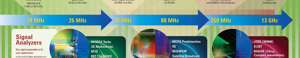
3 Wide Bandwidth Definitions Wide bandwidth means different things to different industries Communications Industry -Cellular Communications (Channel spacing to 20 MHz) -WiMax (to 28 MHz) -4 Carrier WCDMA (to 40 MHz) -6 Carrier WiMax (to 60 MHz) -Ultra wideband (~500 MHz) Aerospace Defense -Narrow band radar (100 MHz, 10 ns pulse) -JTRS sig hopping over 255 MHz -Satellite 200 MHz BW -Chirp and coded radar (>1 GHz)
4 Agenda Wide bandwidth measurement definitions The need for wide bandwidth measurements Types of wide bandwidth measurements Accurate measurements and system calibration Extended calibration Multi-instrument calibration Equipment alternatives for making wide BW measurements Conclusion
5 Broadband signal measurement issues Two general methods of measuring broad band signals: 1. Swept tuned receiver using a sweeping LO and relatively narrow resolution bandwidths. (i.e. sweep across the broadband signal) 2. High speed digitization in the time domain, then performing a Fast Fourier Transform (FFT) (i.e. digitize fast enough to capture the highest frequency component in the band)

6 Swept tuned measurements of broadband signals RF In IF out BPF Detectors Display processor Swept LO With narrow band measurements some information can be gained, such as amplitude and frequency range occupied by signal. Information contained within the signal will be lost because of the reduced BW.

7 Digitization and FFT of broadband signals RF In IF out WBF ADC Display processor Fixed or step tuned All information is captured using a fast digitizer. An FFT is then performed to view signal in the frequency domain
8 Agenda Wide bandwidth measurement definitions The need for wide bandwidth measurements Types of wide bandwidth measurements Accurate measurements and system calibration Extended calibration Multi-instrument calibration Equipment alternatives for making wide BW measurements Conclusion


9 Types of WB measurements There are basically two types of wide BW measurements: 1. Signal amplitude and lobe width for very narrow pulse radar measured in the pulse mode. 2. Phase and amplitude are needed for complete evaluation such as Chirp Radar 200 MHz linear chirp
10 Agenda Wide bandwidth measurement definitions The need for wide bandwidth measurements Types of wide bandwidth measurements Accurate measurements and system calibration Extended calibration Multi-instrument calibration Equipment alternatives for making wide BW measurements Conclusion
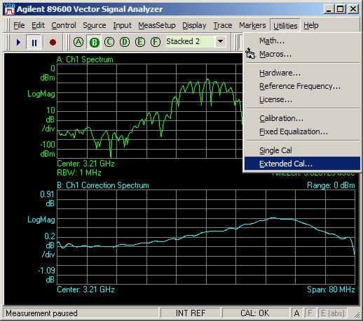
11 Instrument and System Calibration Calibration Q Amplitude error Amplitude Flatness Phase linearity Measured signal θ Ideal Signal Phase linearity error Minimum Error Vector Magnitude The goal is to measure the EVM of the DUT not the EVM introduced by the measuring system EVM I
12 Types of calibration to be presented Different levels of calibration available: Built-in (Internal) calibration available on PSA, X series Extended calibration at a specific center frequency and over the information BW (uses 89601A SW) Wideband extended calibration on multiinstrument systems (89601A, PSA and Scope)
13 Wide Band Block Diagram of the PSA option 122 Third Converter WB Analog IF WB Digital IF UPHB* HB 3 rd LO Calibrator FPGA Low Band 1 st LO 2 nd LO 3 rd LO NB IF *Un-preselected High Band

14 Amplitude and phase characterized comb covering the entire 80 MHz information BW Signal used to calibrate IF path

15 Three loops of calibration Outer Loop IF cal Third Converter WB Analog IF WB Digital IF UPHB HB 1 st LO 2 nd LO Low Band 3 rd LO Calibrator FPGA ADC cal Inner Loop IF cal 3 rd LO NB IF
16 Agenda Wide bandwidth measurement definitions The need for wide bandwidth measurements Types of wide bandwidth measurements Accurate measurements and system calibration Extended calibration Multi-instrument calibration Equipment alternatives for making wide BW measurements Conclusion
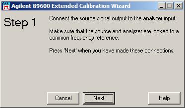
17 Extended Calibration: The next step in system calibration Amplitude and phase calibration and correction at a single frequency (300 MHz) PSA internal calibration (80 MHz) Amplitude and phase calibration and correction at a selected frequency Extended Calibration in 89601A (80 MHz) Amplitude and phase calibration and correction at selected frequency and for multiple instruments Extended Calibration for multiple instruments in 89601A (250 MHz)
18 Extended Calibration for PSA while using µwave preselector (example) PSA user may want to place µwave preselection in the signal path to reduce unwanted signals which may cause overload or images Calibration is required each time the preselector is tuned because of the hysteresis and slight changes in band pass shape. For broad µwave frequency steps the preselector must thermally stabilized before calibration. For other external devices (amps, filters etc) perform an external cal once.
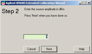
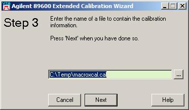
19 Extended Calibration Process Sources Supported: MXG, ESG and PSG


20 EVM and Spectrum display without correcting for µwave preselector ~10% EVM

21 EVM and Spectrum display with µwave preselector correction ~0.6% EVM


22 Comparison of corrections With µwave preselector correction Without µwave preselector correction
23 Measurement system with added devices (amps, filters etc) Added Devices PSA opt 122 plus VSA SW RF IF Digital correction filter Meas. Plane ADC Analysis Source controlled by VSA SW Calibration: measure system to determine the frequency response Correction: apply inverse response with a digital filter Note: The source generates a comb with known amplitude and phase relationships
24 Agenda Wide bandwidth measurement definitions The need for wide bandwidth measurements Types of wide bandwidth measurements Accurate measurements and system calibration Extended calibration Multi-instrument calibration Equipment alternatives for making wide BW measurements Conclusion


25 Calibration of multi-instrument systems 250 MHz to 300 MHz VSA measurement bandwidth 40dB-50dB dynamic range All of the power of the VSA to 50 GHz Powerful Calibration Wizard to ensure phase and magnitude flatness over the full band Works with PSA as downconverter Guided calibration procedure & documented calibration performance Nominal specifications available anticipate 2% to 3% better residual EVM Infiniium Digital Oscilloscope 89601A VSA Software + Cal Wizard PSA MHz IF output to digitizer PSA Spectrum Analyzer + Opt. 123
26 Simplified Block Diagram for System Calibration RF out Calibration source PSG, ESG, MXG 10 MHz in 89601A and Calibration SW on PC 10 MHz in L A N 10 MHz out E4440A Series PSA or N8201A down converter Digitizer (Infiniium Scope) DUT signal RF input MHz out Chan 1 input
 EVM = 2.")
27 Results of using multi-instrument extended cal Satellite Downlink Band (18 GHz) EVM = 2.4 % for 210 MSym/sec QPSK, 300 MHz BW
28 Agenda Wide bandwidth measurement definitions The need for wide bandwidth measurements Types of wide bandwidth measurements Accurate measurements and system calibration Extended calibration Multi-instrument calibration Equipment alternatives for making wide BW measurements Conclusion
29 Agenda Wide bandwidth measurement definitions The need for wide bandwidth measurements Types of wide bandwidth measurements Accurate measurements and system calibration Extended calibration Multi-instrument calibration Equipment alternatives for making wide BW measurements Conclusion
30 Summary of different levels of calibration Type of Calibration Requirements Benefits Comment Internal Included in instrument Calibrates internal IF path to 80MHz Available on PSA Extended 89601A software, PSA, Source Include external devices (preselector, amp, filter) in desired center freq PSA Opt. 235 App Note 1443 Wideband Extended 89601A software, PSA, Scope, Source Full wideband path desired center freq Available Summer 2008

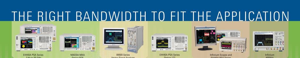
31 Equipment alternatives for measuring wide BW signals (Amplitude measurements*) E4440A PSA Series Spectrum Analyzers To 10 MHz information BW E4440A PSA Series Spectrum Analyzers Option 122 To 80 MHz information BW Internal correction capability *With specific comms options phase is measured
 from the PSA is analyzed by the 89601A software Information BW up to 80")
32 Equipment alternatives for measuring wide BW signals (Phase and amplitude) 89601A software connected to the PSA over LAN or USB Extended correction capability The digitized signal (amplitude and phase) from the PSA is analyzed by the 89601A software Information BW up to 80 MHz

33 Equipment alternatives for measuring wide BW signals (Phase and amplitude) Cont d N9020A MXA spectrum analyzer with 89601A VSA software built-in 25 MHz Information bandwidth
 Cont d")


34 Equipment alternatives for measuring wide BW signals (Phase and amplitude) Cont d PSA, Infiniium Scope and 89601A VSA software Multi-instrument wideband extended calibration capability 250 MHz information bandwidth using PSA as down converter Available Summer 2008
 Cont d DSO 90000A")

35 Equipment alternatives for measuring wide BW signals (Phase and amplitude) Cont d DSO 90000A Infiniium Scope with VSA SW 13 GHz Information Bandwidth, 89601A VSA SW installed in built-in PC
36 Conclusion Three different levels of calibration have been presented: Built-in calibration available on PSA, X series (Created by: Jay Wardle, David Rasmussen, Dave Nunnaly, Joe Tarantino, Bob Matreci) Extended calibration at a specific center frequency and over the information BW (using 89601A SW) (Created by: David Rasmussen, Bob Cutler) Wideband extended calibration on multi-instrument systems (89601A, PSA and Scope) (Created by: Bob Matreci, David Rasmussen, Eric Spotted-Elk)

37
Spectrum Analyzer Training
 Spectrum Analyzer Training Roberto Sacchi Application Engineer roberto_sacchi@agilent.com Page 1 Agenda Introduction Overview: What is Signal Analysis? What Measurements are available? Theory of Operation
Keysight Technologies
 Keysight Technologies Generating Signals Basic CW signal Block diagram Applications Analog Modulation Types of analog modulation Block diagram Applications Digital Modulation Overview of IQ modulation
Advanced RF Measurements You Didn t Know Your Oscilloscope Could Make. Brad Frieden Philip Gresock
 Advanced RF Measurements You Didn t Know Your Oscilloscope Could Make Brad Frieden Philip Gresock Agenda RF measurement challenges Oscilloscope platform overview Typical RF characteristics Bandwidth vs.
Addressing the Challenges of Wideband Radar Signal Generation and Analysis. Marco Vivarelli Digital Sales Specialist
 Addressing the Challenges of Wideband Radar Signal Generation and Analysis Marco Vivarelli Digital Sales Specialist Agenda Challenges of Wideband Signal Generation Challenges of Wideband Signal Analysis
PXA Configuration. Frequency range
 Keysight Technologies Making Wideband Measurements Using the Keysight PXA Signal Analyzer as a Down Converter with Infiniium Oscilloscopes and 89600 VSA Software Application Note Introduction Many applications
Exploring Trends in Technology and Testing in Satellite Communications
 Exploring Trends in Technology and Testing in Satellite Communications Aerospace Defense Symposium Giuseppe Savoia Keysight Technologies Agenda Page 2 Evolving military and commercial satellite communications
Utilizzo del Time Domain per misure EMI
 Utilizzo del Time Domain per misure EMI Roberto Sacchi Measurement Expert Manager - Europe 7 Giugno 2017 Compliance EMI receiver requirements (CISPR 16-1-1 ) range 9 khz - 18 GHz: A normal +/- 2 db absolute
RF Measurements You Didn't Know Your Oscilloscope Could Make
 RF Measurements You Didn't Know Your Oscilloscope Could Make January 21, 2015 Brad Frieden Product Manager Keysight Technologies Agenda RF Measurements using an oscilloscope (30 min) When to use an Oscilloscope
Keysight Technologies Z9070B Wideband Signal Analysis Solution. Technical Overview
 Keysight Technologies Z9070B Wideband Signal Analysis Solution Technical Overview 02 Keysight Z9070B Wideband Signal Analysis Solution - Technical Overview Introduction Wideband commercial, satellite or
GET10B Radar Measurement Basics- Spectrum Analysis of Pulsed Signals. Copyright 2001 Agilent Technologies, Inc.
 GET10B Radar Measurement Basics- Spectrum Analysis of Pulsed Signals Copyright 2001 Agilent Technologies, Inc. Agenda: Power Measurements Module #1: Introduction Module #2: Power Measurements Module #3:
Understanding Low Phase Noise Signals. Presented by: Riadh Said Agilent Technologies, Inc.
 Understanding Low Phase Noise Signals Presented by: Riadh Said Agilent Technologies, Inc. Introduction Instabilities in the frequency or phase of a signal are caused by a number of different effects. Each
Addressing the Challenges of Wideband Radar and SatCom Measurements
 2011 Agilent RF/uW Symposium Addressing the Challenges of Wideband Radar and SatCom Measurements Presented by: Giuseppe Savoia, Agilent Technologies Agenda Applications requiring broadband uw test equipment
Testing RFIC Power Amplifiers with Envelope Tracking. April 2014
 Testing RFIC Power Amplifiers with Envelope Tracking April 2014 1 Agenda Key Test Challenges Addressing Test Challenges New emerging technologies such as envelope tracking and DPD and their implications
RF Fundamentals Part 2 Spectral Analysis
 Spectral Analysis Dec 8, 2016 Kevin Nguyen Keysight Technologies Agenda Overview Theory of Operation Traditional Spectrum Analyzers Modern Signal Analyzers Specifications Features Wrap-up Page 2 Overview
Integration of Measurement Equipment in a Matlab Environment for the Example of Radar Chirps
 Integration of Measurement Equipment in a Matlab Environment for the Example of Radar Chirps Špiro Moškov RF and Wireless Application Engineer Agilent Technologies Page 1 Agenda Signal creation and instrument
3250 Series Spectrum Analyzer
 The most important thing we build is trust ADVANCED ELECTRONIC SOLUTIONS AVIATION SERVICES COMMUNICATIONS AND CONNECTIVITY MISSION SYSTEMS 3250 Series Spectrum Analyzer > Agenda Introduction
8 Hints for Better Spectrum Analysis. Application Note
 8 Hints for Better Spectrum Analysis Application Note 1286-1 The Spectrum Analyzer The spectrum analyzer, like an oscilloscope, is a basic tool used for observing signals. Where the oscilloscope provides
Understanding RF and Microwave Analysis Basics
 Understanding RF and Microwave Analysis Basics Kimberly Cassacia Product Line Brand Manager Keysight Technologies Agenda µw Analysis Basics Page 2 RF Signal Analyzer Overview & Basic Settings Overview
Keysight Technologies N9051B Pulse Measurement Software X-Series Signal Analyzers. Technical Overview
 Keysight Technologies N9051B Pulse Measurement Software X-Series Signal Analyzers Technical Overview 02 Keysight N9051B Pulse Measurement Software X-Series Signal Analyzers - Technical Overview Features
Agilent Back to Basics. Spectrum Analysis Back to Basics. Presented by: Michel Joussemet
 Agilent Back to Basics Spectrum Analysis Back to Basics Presented by: Michel Joussemet Aerospace and Defense Symposium 2007 EuMw 2007 Agilent Workshop Agenda Introduction Overview: What is Signal Analysis?
Advances in RF and Microwave Measurement Technology
 1 Advances in RF and Microwave Measurement Technology Rejwan Ali Marketing Engineer NI Africa and Oceania New Demands in Modern RF and Microwave Test In semiconductor and wireless, technologies such as
Even as fourth-generation (4G) cellular. Wideband Millimeter Wave Test Bed for 60 GHz Power Amplifier Digital Predistortion.
 cellular. Wideband Millimeter Wave Test Bed for 60 GHz Power Amplifier Digital Predistortion.") Wideband Millimeter Wave Test Bed for 60 GHz Power Amplifier Digital Predistortion Stephen J. Kovacic, Foad Arfarei Maleksadeh, Hassan Sarbishaei Skyworks Solutions, Woburn, Mass. Mike Millhaem, Michel
Wideband Millimeter Wave Test Bed for 60 GHz Power Amplifier Digital Predistortion Stephen J. Kovacic, Foad Arfarei Maleksadeh, Hassan Sarbishaei Skyworks Solutions, Woburn, Mass. Mike Millhaem, Michel
22 Marzo 2012 IFEMA, Madrid spain.ni.com/nidays.
 22 Marzo 2012 IFEMA, Madrid spain.ni.com/nidays www.infoplc.net The Art of Benchmarking Speed PXI Versus Rack-and-Stack Test Equipment Filippo Persia Systems Engineer Automated Test Mediterranean Region
Advances in RF and Microwave Measurement Technology
 1 Advances in RF and Microwave Measurement Technology Chi Xu Certified LabVIEW Architect Certified TestStand Architect New Demands in Modern RF and Microwave Test In semiconductor and wireless, technologies
The Value of Pre-Selection in EMC Testing. Scott Niemiec Application Engineer
 The Value of Pre-Selection in EMC Testing Scott Niemiec Application Engineer Video Demonstrating Benefit of Pre-selection 400MHz -1GHz Sweep with RBW = 120kHz Yellow: w/ preselection Green: w/o pre-selection
Agilent. E8267C PSG Vector Signal Generator E8257C PSG Analog Signal Generator E8247C PSG CW Signal Generator
 Agilent E8267C PSG Vector Signal Generator E8257C PSG Analog Signal Generator E8247C PSG CW Signal Generator Aerospace and defense systems Component measurements Satellite communications Broadband microwave
Antenna Measurement using Vector Network Analyzer. Jong-hwan Keum Agilent Technologies
 Antenna Measurement using Vector Network Analyzer Jong-hwan Keum Agilent Technologies Agenda Overview Antenna Measurement System Configuration(Examples) Antenna Measurement System Design Considerations
Introducing the Keysight RF PXIe Vector Signal Analyzer & Generator M9391A & M9381A. Updated: August 2015
 Introducing the Keysight RF PXIe Vector Signal Analyzer & Generator M9391A & M9381A Updated: August 2015 Agenda Page 2 M9391A PXIe vector signal generator M9381A PXIe vector signal analyzer M9380A PXIe
8 Hints for Better Spectrum Analysis. Application Note
 8 Hints for Better Spectrum Analysis Application Note 1286-1 The Spectrum Analyzer The spectrum analyzer, like an oscilloscope, is a basic tool used for observing signals. Where the oscilloscope provides
Understanding Probability of Intercept for Intermittent Signals
 2013 Understanding Probability of Intercept for Intermittent Signals Richard Overdorf & Rob Bordow Agilent Technologies Agenda Use Cases and Signals Time domain vs. Frequency Domain Probability of Intercept
PN9000 PULSED CARRIER MEASUREMENTS
 The specialist of Phase noise Measurements PN9000 PULSED CARRIER MEASUREMENTS Carrier frequency: 2.7 GHz - PRF: 5 khz Duty cycle: 1% Page 1 / 12 Introduction When measuring a pulse modulated signal the
Fast, Simple, Accurate Applies to Mixers Too
 Fast, Simple, Accurate Applies to Mixers Too Joel Dunsmore, Ph.D. Agilent Fellow Component Test Division R&D 1 2013 Agilent Technologies All-in-one Measurement Systems SCMM Performs S-parameter, IMD, Gain
Understanding New Pulse-analysis Techniques
 Understanding New Pulse-analysis Techniques Giuseppe Savoia Keysight Technologies Aerospace Defense Symposium Agenda Concept for Radar/Pulse signal analysis AD Symposium Page 2 Vector signal analyzers
Agilent Spectrum Analysis Basics. Application Note 150
 Agilent Spectrum Analysis Basics Application Note 150 Table of Contents Chapter 1 Introduction.......................................................4 Frequency domain versus time domain.......................................4
Agilent PSA Series Spectrum Analyzers 40 and 80 MHz Bandwidth Digitizers
 Agilent PSA Series Spectrum Analyzers 40 and 80 MHz Bandwidth Digitizers Technical Overview with Self-Guided Demonstration 40 MHz Bandwidth Digitizer, Option 140 80 MHz Bandwidth Digitizer, Option 122
Successful Modulation Analysis in 3 Steps. Ben Zarlingo Application Specialist Agilent Technologies Inc. January 22, 2014
 Successful Modulation Analysis in 3 Steps Ben Zarlingo Application Specialist Agilent Technologies Inc. January 22, 2014 Agilent Technologies, Inc. 2014 This Presentation Focus on Design, Validation, Troubleshooting
Making Noise in RF Receivers Simulate Real-World Signals with Signal Generators
 Making Noise in RF Receivers Simulate Real-World Signals with Signal Generators Noise is an unwanted signal. In communication systems, noise affects both transmitter and receiver performance. It degrades
Keysight Technologies A Flexible Testbed to Evaluate Potential Co-Existence Issues Between Radar and Wireless
 Keysight Technologies A Flexible Testbed to Evaluate Potential Co-Existence Issues Between Radar and Wireless Application Note Photo courtesy US Department of Defense Problem: Radar and wireless may interfere
EMC Training. Ing Angelo Cereser Mobile:
 EMC Training Ing Angelo Cereser angelo.cereser@microlease.com Mobile: 335 57 88 293 Dott Mirko Bombelli mirko.bombelli@microlease.com Mobile: 335 12 36 792 Agenda Introduzione alle misure EMI Terminologia;
Spectrum Analysis Back to Basics
 Spectrum Analysis Back to Basics Agilent Technologies 1 Agenda Introduction Overview: What is Spectrum and Signal Analysis? What Measurements are available? Theory of Operation Specifications Modern Signal
Simulating and Testing of Signal Processing Methods for Frequency Stepped Chirp Radar
 Test & Measurement Simulating and Testing of Signal Processing Methods for Frequency Stepped Chirp Radar Modern radar systems serve a broad range of commercial, civil, scientific and military applications.
DFS (Dynamic Frequency Selection) Introduction and Test Solution
 Introduction and Test Solution") DFS (Dynamic Frequency Selection) Introduction Sept. 2015 Present by Brian Chi Brian-tn_chi@keysight.com Keysight Technologies Agenda Introduction to DFS DFS Radar Profiles Definition DFS test procedure
DFS (Dynamic Frequency Selection) Introduction Sept. 2015 Present by Brian Chi Brian-tn_chi@keysight.com Keysight Technologies Agenda Introduction to DFS DFS Radar Profiles Definition DFS test procedure
Module 1B RF Test & Measurement
 1 EECE 411 Antennas and Propagation Module 1B RF Test & Measurement Introduction to Spectrum Analyzers 2 Why Measure the Spectrum of a Signal? to characterize noise and interference to measure distortion
Traceability and Modulated-Signal Measurements
 Traceability and Modulated-Signal Measurements Kate A. Remley 1, Dylan F. Williams 1, Paul D. Hale 2 and Dominique Schreurs 3 1. NIST Electromagnetics Division 2. NIST Optoelectronics Division 3. K.U.
Ten Things You Should Know About MIMO
 Ten Things You Should Know About MIMO 4G World 2009 presented by: David L. Barner www/agilent.com/find/4gworld Copyright 2009 Agilent Technologies, Inc. The Full Agenda Intro System Operation 1: Cellular
Antenna Measurements using Modulated Signals
 Antenna Measurements using Modulated Signals Roger Dygert MI Technologies, 1125 Satellite Boulevard, Suite 100 Suwanee, GA 30024-4629 Abstract Antenna test engineers are faced with testing increasingly
Radar System Design and Interference Analysis Using Agilent SystemVue
 Radar System Design and Interference Analysis Using Agilent SystemVue Introduction Application Note By David Leiss, Sr. Consultant EEsof EDA Anurag Bhargava, Application Engineer EEsof EDA Agilent Technologies
TESTING METHODS AND ERROR BUDGET ANALYSIS OF A SOFTWARE DEFINED RADIO By Richard Overdorf
 TESTING METHODS AND ERROR BUDGET ANALYSIS OF A SOFTWARE DEFINED RADIO By Richard Overdorf SDR Considerations Data rates Voice Image Data Streaming Video Environment Distance Terrain High traffic/low traffic
Real-Time Digital Down-Conversion with Equalization
 Real-Time Digital Down-Conversion with Equalization February 20, 2019 By Alexander Taratorin, Anatoli Stein, Valeriy Serebryanskiy and Lauri Viitas DOWN CONVERSION PRINCIPLE Down conversion is basic operation
Keysight Technologies E8740A Automotive Radar Signal Analysis and Generation Solution
 Keysight Technologies E8740A Automotive Radar Signal Analysis and Generation Solution Configuration Guide DSOS804A High-definition oscilloscope M895A 65 GSa/s arbitrary waveform generator N904B UXA signal
9 Best Practices for Optimizing Your Signal Generator Part 2 Making Better Measurements
 9 Best Practices for Optimizing Your Signal Generator Part 2 Making Better Measurements In consumer wireless, military communications, or radar, you face an ongoing bandwidth crunch in a spectrum that
Pulsed VNA Measurements:
 Pulsed VNA Measurements: The Need to Null! January 21, 2004 presented by: Loren Betts Copyright 2004 Agilent Technologies, Inc. Agenda Pulsed RF Devices Pulsed Signal Domains VNA Spectral Nulling Measurement
Basics Of The Spectrum Analyzer
 Basics Of The Spectrum Analyzer 1 / 6 2 / 6 3 / 6 Basics Of The Spectrum Analyzer Remember that the spectrum analyzers User's Guides are also located in the lab. Like an oscilloscope, a spectrum analyzer
Dive deep into interference analysis
 Dive deep into interference analysis Dive deep into interference analysis Contents 1. Introducing Narda Outstanding features 2. Basics IDA 2 3. IDA 2 presentation How IDA 2 is used: 1) Detect 2) Analyze
TETRA Tx Test Solution
 Product Introduction TETRA Tx Test Solution Signal Analyzer Reference Specifications ETSI EN 300 394-1 V3.3.1(2015-04) / Part1: Radio ETSI TS 100 392-2 V3.6.1(2013-05) / Part2: Air Interface May. 2016
Keysight Technologies Gustaaf Sutorius
 1 1 mmw Seminar 2017 Keysight Technologies 18-04-2018 Gustaaf Sutorius Introduction & Agenda Why mmwave Industry needs & mmwave challenges Generating mmwave Analyzing mmwave Characterizing mmwave components
PXIe Contents SPECIFICATIONS. 14 GHz and 26.5 GHz Vector Signal Analyzer
 SPECIFICATIONS PXIe-5668 14 GHz and 26.5 GHz Vector Signal Analyzer These specifications apply to the PXIe-5668 (14 GHz) Vector Signal Analyzer and the PXIe-5668 (26.5 GHz) Vector Signal Analyzer with
Back to Basics: Signal Generation. Back to Basics Training Copyright Agilent 1 Nov 2012
 Back to Basics: Signal Generation 1 Agenda The need for creating test signals Aerospace Defense to Communications Generating Signals No modulation Analog Modulation Composite Modulation Signal Generator
Agilent E8267C PSG Vector Signal Generator
 Agilent E8267C PSG Vector Signal Generator Configuration Guide E8267C PSG vector signal generator This guide is intended to assist you with the ordering process of the PSG vector signal generators. Standard
Ultra Wideband Indoor Radio Channel Measurements
 Ultra Wideband Indoor Radio Channel Measurements Matti Hämäläinen, Timo Pätsi, Veikko Hovinen Centre for Wireless Communications P.O.Box 4500 FIN-90014 University of Oulu, FINLAND email: matti.hamalainen@ee.oulu.fi
MAKING TRANSIENT ANTENNA MEASUREMENTS
 MAKING TRANSIENT ANTENNA MEASUREMENTS Roger Dygert, Steven R. Nichols MI Technologies, 1125 Satellite Boulevard, Suite 100 Suwanee, GA 30024-4629 ABSTRACT In addition to steady state performance, antennas
Specifications Guide
 Agilent Technologies PSA Series Spectrum Analyzers This manual provides documentation for the following instruments: E4443A (3 Hz 6.7 GHz) E4445A (3 Hz 13.2 GHz) E4440A (3 Hz 26.5 GHz) E4446A (3 Hz 44
40/80 MHz. Agilent PSA Series Spectrum Analyzers 40 and 80 MHz Bandwidth Digitizers. Analysis Bandwidth Now Available On 50 GHz PSA!
 40/80 MHz Analysis Bandwidth Now Available On 50 GHz PSA! Agilent PSA Series Spectrum Analyzers 40 and 80 MHz Bandwidth Digitizers Industry s First Spectrum Analyzer with a 14 Bit, 80 MHz Bandwidth Digitizer
8853Q Spectrum Analyzer
 Increases Productivity by Providing a Complete Set of Spectrum Analysis Tests in One Instrument Intuitive User Interface Shortens Learning Curve Full-Featured, High-Performance, Remote Operation Automated
PXI WiMAX Measurement Suite Data Sheet
 PXI WiMAX Measurement Suite Data Sheet The most important thing we build is trust Transmit power Spectral mask Occupied bandwidth EVM (all, data only, pilots only) Frequency error Gain imbalance, Skew
Transmitter Design and Measurement Challenges
 Transmitter Design and Measurement Challenges Based on the book: LTE and the Evolution to 4G Wireless Chapter 6.4 4G World 2009 presented by: David L. Barner www/agilent.com/find/4gworld 1 Agilent Technologies,
Interference Analysis and Spectrum Monitor Seminar
 Interference Analysis and Spectrum Monitor Seminar Handheld RF & Microwave Instruments Andrew Benn Business Development Manager Agilent Technologies Wednesday 12 th October 2011 1 Agilent Technologies,
Multi-Signal, Multi-Format Analysis With Agilent VSA Software
 Multi-Signal, Multi-Format Analysis With Agilent 89600 VSA Software Ken Voelker Agilent Technologies Inc. April 2012 1 April, 25 2012 Agenda Introduction: New Measurement Challenges Multi-Measurements
Techniques for Characterizing Spurious Signals
 Techniques for Characterizing Spurious Signals October 21, 2014 Riadh Said Product Manager Microwave and Communications Division Keysight Technologies Our Goals today Review the sweep time equation to
N9051A Pulse Measurement Software
 N9051A Pulse Measurement Software X-Series Signal Analyzers and PSA Series Spectrum Analyzers Technical Overview Characterize pulse performance using a wide range of parameters including pulse width, rise/fall
Keysight Technologies 8 Hints for Making Better Measurements Using RF Signal Generators. Application Note
 Keysight Technologies 8 Hints for Making Better Measurements Using RF Signal Generators Application Note 02 Keysight 8 Hints for Making Better Measurements Using RF Signal Generators - Application Note
Characterization and Compensation of Non-Linear Effects in Components. Dr. Florian Ramian
 Characterization and Compensation of Non-Linear Effects in Components Dr. Florian Ramian Agenda ı Introduction: What Is a Non-Linear Device ı Characterization of Non-Linear Devices Characterization Parameters
Payload measurements with digital signals. Markus Lörner, Product Management Signal Generation Dr. Susanne Hirschmann, Signal Processing Development
 Payload measurements with digital signals Markus Lörner, Product Management Signal Generation Dr. Susanne Hirschmann, Signal Processing Development Agenda ı Why test with modulated signals? ı Test environment
Técnicas de Caracterização de RWR/MAGE usando instrumentos COTS da Agilent 24 de Setembro de 2008
 Técnicas de Caracterização de RWR/MAGE usando instrumentos COTS da Agilent 24 de Setembro de 2008 Mauricio Kobayashi Eng. Vendas Page 1 Agenda Functional Performance Test Alternatives RWR Test Model Tests
Transcom Instruments. Product Brochure TRANSCOM INSTRUMENTS. Product Brochure
 TRANSCOM INSTRUMENTS Product Brochure Transcom Instruments Product Brochure Vector Signal Generator Overview Vector Signal Generator is a high performance vector signal generator. It can generate arbitrary
Keysight Technologies PNA-X Series Microwave Network Analyzers
 Keysight Technologies PNA-X Series Microwave Network Analyzers Active-Device Characterization in Pulsed Operation Using the PNA-X Application Note Introduction Vector network analyzers (VNA) are the common
Improving Amplitude Accuracy with Next-Generation Signal Generators
 Improving Amplitude Accuracy with Next-Generation Signal Generators Generate True Performance Signal generators offer precise and highly stable test signals for a variety of components and systems test
AESA Exciter Receiver Modules (Synthesizer, IF Receiver and Waveform Generator)
") AESA Exciter Receiver Modules (Synthesizer, IF Receiver and Waveform Generator) The Synthesizer (SYNTH) Module, IF Receiver (IFRx) Module and Waveform generator (WFG) Module aredesigned and developed by
AESA Exciter Receiver Modules (Synthesizer, IF Receiver and Waveform Generator) The Synthesizer (SYNTH) Module, IF Receiver (IFRx) Module and Waveform generator (WFG) Module aredesigned and developed by
Measuring Photonic, Optoelectronic and Electro optic S parameters using an advanced photonic module
 Measuring Photonic, Optoelectronic and Electro optic S parameters using an advanced photonic module APPLICATION NOTE This application note describes the procedure for electro-optic measurements of both
Agilent Vector Signal Analysis Basics. Application Note
 Agilent Vector Signal Analysis Basics Application Note Table of Contents Vector signal Analysis 3 VSA measurement advantages 4 VSA measurement concepts and theory of operation 6 Data windowing leakage
Vector Signal Generator Module. Transcom Instruments.
 Vector Signal Generator Module G6 Transcom Instruments Overview of G6 G6 vector signal generator module is a high performance vector signal generator. It supports arbitrary wave signal, continuous wave
Agilent PSA Series Spectrum Analyzers WLAN Measurement Personality
 Agilent PSA Series Spectrum Analyzers WLAN Measurement Personality Technical Overview with Self-Guided Demonstration Option 217 Intuitive, easy-to-use, one-box solution Simplified test setup with WLAN
TRANSCOM Manufacturing & Education
 www.transcomwireless.com 1 G6 Vector Signal Generator Overview G6 Vector Signal Generator is a high performance vector signal generator. It can generate arbitrary wave signal, continuous wave signal, common
On site RF troubleshooting for installation and maintenance
 On site RF troubleshooting for installation and maintenance Measure of interferers, high power for microwave links or low power for Base Stations uplink Troubleshooting of cables, or waveguides, and antennas
Abstract: Stringent system specifications impose tough performance requirements on the RF and microwave cables used in aerospace and defense
 1 Abstract: Stringent system specifications impose tough performance requirements on the RF and microwave cables used in aerospace and defense communication systems. With typical tools, it can be very
Production Test and Spectral Monitoring
 1 Production Test and Spectral Monitoring Stephen Plumb Key RF Building Blocks Symbol Name Types Function Amplifier (2 port) Power Amplifier Low Noise Amplifier Amplify signal before transmission (high
R&S FSWP Phase Noise Analyzer Specifications
 R&S FSWP Phase Noise Analyzer Specifications Data Sheet Version 06.00 CONTENTS Definitions... 4 Specifications... 5 Frequency... 5 Phase noise measurements... 5 Phase noise sensitivity with R&S FSWP-B61
Pulsed S-Parameter Measurements using the ZVA network Analyzer
 Pulsed S-Parameter Measurements using the ZVA network Analyzer 1 Pulse Profile measurements ZVA Advanced Network Analyser 3 Motivation for Pulsed Measurements Typical Applications Avoid destruction of
PNA Family Microwave Network Analyzers (N522x/3x/4xB) CONFIGURATION GUIDE
 CONFIGURATION GUIDE") PNA Family Microwave Network Analyzers (N522x/3x/4xB) CONFIGURATION GUIDE Table of Contents PNA Family Network Analyzer Configurations... 05 Test set and power configuration options...05 Hardware options...
PNA Family Microwave Network Analyzers (N522x/3x/4xB) CONFIGURATION GUIDE Table of Contents PNA Family Network Analyzer Configurations... 05 Test set and power configuration options...05 Hardware options...
Keysight Technologies N7621B
 Keysight Technologies N7621B Signal Studio for Multitone Distortion Technical Overview Create Keysight Technologies, Inc. validated and performance optimized multitone and noise power ratio (NPR) signals
Addressing the Design-to-Test Challenges for SDR and Cognitive Radio
 Addressing the Design-to-Test Challenges Bob Cutler and Greg Jue, Agilent Technologies Software Defined Radios Flexibility Radio can support multiple waveforms: Different formats, Different revisions of
Data Sheet SC5317 & SC5318A. 6 GHz to 26.5 GHz RF Downconverter SignalCore, Inc. All Rights Reserved
 Data Sheet SC5317 & SC5318A 6 GHz to 26.5 GHz RF Downconverter www.signalcore.com 2018 SignalCore, Inc. All Rights Reserved Definition of Terms 1 Table of Contents 1. Definition of Terms... 2 2. Description...
Keysight Technologies Compatibility of USB Power Sensors with Keysight Instruments. Application Note
 Keysight Technologies Compatibility of USB Power Sensors with Keysight Instruments Application Note 02 Keysight Compatibility of USB Power Sensors with Keysight Instruments Application Note Table of Contents
Agilent E6651A Mobile WiMAX Test Set
 Agilent E6651A Mobile WiMAX Test Set Preliminary Technical Overview Accelerate time-to-market for your IEEE802.16e subscriber station designs The E6651A represents a significant breakthrough in Mobile
Transforming MIMO Test
 Transforming MIMO Test MIMO channel modeling and emulation test challenges Presented by: Kevin Bertlin PXB Product Engineer Page 1 Outline Wireless Technologies Review Multipath Fading and Antenna Diversity
Measurements 2: Network Analysis
 Measurements 2: Network Analysis Fritz Caspers CAS, Aarhus, June 2010 Contents Scalar network analysis Vector network analysis Early concepts Modern instrumentation Calibration methods Time domain (synthetic
Transmission Signal Quality Comparison of SCM and OFDM according to the Phase Noise Characteristics of the Local Oscillator
 Transmission Signal Quality Comparison of SCM and OFDM according to the Phase Noise Characteristics of the Local Oscillator Gwang-Yeol You*, Seung-Chul SHIN** * Electronic Measurement Group, Wireless Communication
LIMITATION OF GPS RECEIVER CALIBRATIONS
 LIMITATION OF GPS RECEIVER CALIBRATIONS G. Paul Landis SFA, Inc./Naval Research Laboratory 4555 Overlook Ave., S.W. Washington, D.C. 20375, USA Tel: (202) 404-7061; Fax: (202) 767-2845 E-Mail: landis@juno.nrl.navy.mil
A 1.7-to-2.2GHz Full-Duplex Transceiver System with >50dB Self-Interference Cancellation over 42MHz Bandwidth
 A 1.7-to-2.2GHz Full-Duplex Transceiver System with >50dB Self-Interference Cancellation Tong Zhang, Ali Najafi, Chenxin Su, Jacques C. Rudell University of Washington, Seattle Feb. 8, 2017 International
M8195A 65 GSa/s Arbitrary Waveform Generator
 Arbitrary Waveform Generator New AWG with the highest combination of speed, bandwidth and channel density Juergen Beck Vice President & General Mgr. Digital & Photonic Test Division September 10, 2014