Agilent Technologies PSA Series Spectrum Analyzers Test and Adjustment Software
|
|
|
- Isaac Greene
- 6 years ago
- Views:
Transcription
1 Test System Overview Agilent Technologies PSA Series Spectrum Analyzers Test and Adjustment Software Test System Overview The Agilent Technologies test system is designed to verify the performance of the PSA series spectrum analyzers and ensure that they meet published specifications. Follow the links below to view a listing of the test system requirements, test equipment required, a full description of each performance test, a full description of each adjustment, the associated troubleshooting procedures should any of the tests fail, and the Test Management Environment (TME) software help. Getting Started -- steps for installing and running the test software Required Equipment -- test equipment, ESD precautions Performance Tests -- a list of all performance tests Adjustments -- a list of all adjustments Troubleshooting -- troubleshooting performance test failures Memory Initialization Utilities -- utilities to write serial number information, and to reset instrument statistical data Test Management Environment (TME) help -- information on setting up and using the (1 of 2) [5/29/2003 8:46:47 AM]
2 Test System Overview TME software NOTE: If your analyzer has firmware revision A.03.xx, click here for information about possible conflicts between Option 266 and Basic Mode. Copyright Agilent Technologies, 2000, 2001, (2 of 2) [5/29/2003 8:46:47 AM]
3 Before You Start Agilent Technologies PSA Series Spectrum Analyzers Test and Adjustment Software Before You Start Check the following before starting the performance test software. 1. Ensure minimum requirements of the PC: Controller Requirements 200 MHz Pentium processor or higher 64 MB RAM or more 200 MB available hard drive Operating system: Windows 2000, service pack 3, or Windows NT, service pack 6A. (Windows XP is not supported at this time) A standalone PC to GPIB controller with IEEE protocol A VISA communications interface IE 4.0 or higher 2. Ensure computer has a GPIB Interface Card installed in it before running the software installation. The recommended card is Agilent model part number 82350A. You may also use a National Instruments model part number AT-GPIB/TNT or PCI-GPIB. 3. Ensure you have the proper test equipment. Let all the test equipment and PSA warm up in accordance to instrument specifications. [5/29/2003 8:46:48 AM]
4 PSA Test Equipment Agilent Technologies PSA Series Spectrum Analyzers Test and Adjustment Software Test Equipment Instrument Signal Sources Synthesized Signal Generator Synthesized Signal Generator Sweep Signal Generator (2 required, only 1 needs to be Option 008) Critical Specifications Frequency: 1 MHz to 2.5 GHz Spectral purity: 7 MHz to 1321 MHz Spurious (non-harmonic): at 50 MHz -90 dbc 2.56 GHz, < -78 dbc Harmonics: < -30 dbc +13 dbm SSB Phase Noise: -106 dbc/hz at 1 khz offset (or residual FM 0.5 Hz, 300 Hz to 3 khz integration BW). VSWR: < 1.5:1 Frequency: 100 khz to 6.0 GHz Spectral Purity: SSB Phase 1 GHz, 20 khz offset = -134 dbc/hz Harmonics: dbm output Frequency: 10 MHz to 26.5 GHz Frequency Resolution: 1 Hz Harmonic level: < -40 dbc Amplitude range: -20dBm to +13 Amplitude resolution: 0.02 Harmonic level: < 2 GHz, < -30 dbc 2 GHz & < 26.5 GHz, < -50 dbc VSWR: < 20 GHz, 1.6:1 31 GHz, 1.8:1 Recommended Agilent Model Number Alternative Agilent Model Number Use A A, P, T 8665B (Option 004) P 83630B (Option 008) 83630A (Option 008), 83640A/B (Option 008), 83650A/B (Option 008) A, P, T (1 of 7) [5/29/2003 8:46:54 AM]
5 PSA Test Equipment Sweep Signal Generator (Needed for E4446A, E4448A) Digital Signal Generator Function Generator Counters Universal Counter Frequency: 10 MHz to 50 GHz Frequency Resolution: 1 Hz Harmonic level: < -40 dbc Amplitude range: -20dBm to +13 Amplitude resolution: 0.02 Harmonic level: < 2 GHz, < -30 dbc 2 GHz & < 26.5 GHz, < -50 dbc 26.5 GHz, < -40 dbc VSWR: < 20 GHz, 1.6:1 40 GHz, 1.8:1 50 GHz, 2.0:1 Ability to create 64 tones across a 5 MHz span synchronously, 5 MHz to 10 MHz Resolution: 0.02 Frequency: 1 Hz to 15 MHz Amplitude Resolution: 0.1 mv Harmonic Distortion: -35 dbc Frequency: 10 MHz Gate time: 10 to 100 seconds Must be capable of measuring signal at +7 dbm (0.5 Vrms) Meters Digital Voltmeter AC Accuracy (SETACV SYNC mode): ± 4% of reading Power Meter Dual Channel Absolute Accuracy: ± 0.5% Resolution: 0.01 db Reference Accuracy: 1.2% Power Reference Accuracy: ± 0.9% Compatible with Agilent 8480 series power sensors db relative mode Power Sensor (2 required) Power Sensor Power Sensor (Needed for E4440A, E4443A, E4445A) Frequency Range: 100 khz to 4.2 GHz. VSWR: at 50 MHz: MHz to 4 GHz: 1.30:1 Type-N (m) Option H84 Cal Factor: Characterized by standards lab to: ± 0.6% 2 Frequency Range: 50 MHz to 8 GHz. VSWR: at 50 MHz: 1.05:1 700 MHz to 3 GHz: 1.22:1 Option H84 Cal Factor: Characterized by standards lab to: ± 0.6% Frequency Range: 50 MHz to 26.5 GHz Amplitude Range: -20 to +10 db VSWR: 50 MHz to 100 MHz: 1.15:1 100 MHz to 2 GHz: 1.10:1 2 GHz to 12.4 GHz: 1.15: GHz to 18 GHz: 1.20:1 18 GHz to 26.5 GHz: 1.25:1 RF Connector: 2.4 mm (M) 83650B (Option 008) E4433B (Option UND) 33120A (Option 001) 83650A E4437B (Option UND FW datecode: B.02.24) 33120A A, P, T P A, P 53132A P, T 3458A A, T E4419B E4419A A, P 8482A (Option H84) 8481A (Option H84) 8482A STD (Will increase measurement uncertainty) 8481A STD, 8485A STD (Will increase measurement uncertainty) A, P 8485A 8487A A, P P (2 of 7) [5/29/2003 8:46:54 AM]
6 PSA Test Equipment Power Sensor (Needed for E4446A, E4448A) Standards Frequency Standard 50 MHz, -25 dbm Calibrator Attenuators 10 db Step Attenuator 1 db Step Attenuator Frequency Range: 50 MHz to 50 GHz Amplitude Range: -20 to +20 db VSWR: 50 MHz to 100 MHz: 1.15:1 100 MHz to 2 GHz: 1.10:1 2 GHz to 12.4 GHz: 1.15: GHz to 18 GHz: 1.20:1 18 GHz to 26.5 GHz: 1.25: GHz to 40 GHz: 1.30:1 40 GHz to 50 GHz: 1.50:1 RF Connector: 2.4 mm coaxial (M) 8487A A, P Frequency: 10 MHz 5071A 5061B A, P Accuracy: < ± 1e10-10 Frequency Drift: < 2.5 khz Typical VSWR: 1.06:1 Output Power Variation: ±.004 db Total Harmonic Content: -45 dbc Range: 0 to 110 db Accuracy: Characterized by standards lab to: ± /10 db step 3 Calibrated at 50 MHz VSWR: at 50 MHz: 1.05:1 Range: 0 to 11 db Accuracy: Characterized by standards lab to: ± 0.01 db 3 Calibrated at 50 MHz VSWR: at 50 MHz: 1.05:1 Z5602A Opt H51 Opt H35 for BAB Opt H24 for E4446A, E4448A 8496G 8496H P 8494G 8494H P Attenuator 11716A P Type N connector kit to connect the 8496G to the 8494G Interconnect Kit Attenuator Driver Compatible with the 8496G and 8494G step attenuators A P 6 db Fixed Attenuator 20 db Fixed Attenuator 20 db Fixed Attenuator Terminations Type N (m) 6 db Type N (m, f) VSWR: at 50 MHz: db Type N (m, f) Accuracy: ± 0.5 db VSWR: DC to 8 GHz: 1.20:1 20 db 3.5 mm (m, f) Accuracy: ± 0.5 db VSWR: DC to 8 GHz: 1.20:1 50 W Frequency: 1 MHz to 4 GHz VSWR: 4 GHz: 1.05:1 3.5 mm (m) 50 ohm VSWR: 26.5 GHz: 1.12:1 2.4 mm (f) (Needed for E4446A, E4448A) 50 ohm Frequency: DC to 50 GHz 8491A P (Options 006 & H47) 8491A A (Option 020) 8493C (Option 020) A 909A (Option 012) P, T 909D P 85138B P BNC 50 ohm P A Miscellaneous Devices Power Splitter Frequency: 9 khz to 3 GHz Type N (f) VSWR: 1.10: A P (3 of 7) [5/29/2003 8:46:54 AM]
7 PSA Test Equipment Power Splitter Power Splitter (Needed for E4446A, E4448A) Directional Bridge Directional Coupler (2 required) Frequency: DC to 26.5 GHz 3.5 mm (f) VSWR: DC to 3 GHz: < 1.06:1 3 GHz to 26.5 GHz: <1.22:1 Insertion Loss: DC to 8 GHz: 6.5 db (Typical) 8 to 18 GHz: 7.0 db 18 to 26.5 GHz: 7.3 db Frequency: DC to 50 GHz 2.4 mm (f) VSWR: 18 GHz:: < 1.29:1 18 GHz to 26.5 GHz: <1.20:1 40 GHz:: < 1.50:1 50 GHz:: < 1.65:1 Insertion Loss: DC to 18 GHz: 6.0 db (Typical) 18 to 26.5 GHz: 7.0 db 26.5 to 40 GHz: 8.0 db 40 to 50 GHz: 8.5 db Frequency Range: 5 MHz to 3 GHz Directivity: 5 MHz: 30 db 5 MHz to 2 GHz: 40 db 2 GHz to 3 GHz: 30 db, VSWR: 2 GHz: 1.15:1 3 GHz: 1.22:1 Insertion Loss: 1.5, +0.1 db/ghz Coupling (nominal): 16 db Type N (f) 2 GHz to 20 GHz SMA (f) Directivity >16 db Transmission arm loss: <1.5dB (nominal) Coupled Arm Loss: ~10dB (nominal) VSWR: 1.35: B (Option H30) 11667B (std) 11667C P 86205A P 87300B P DC Probe 11002A 11003A A High Frequency Probe 300 khz to 3 GHz 85024A T Input Resistance: 1 M ohm (nominal) Negative Detector 0.01 to 26.5 GHz 33330C A ± 0.6 db to 18 GHz Bias Adjustment Board E A P Cables APC 3.5 mm (m) (m) (2 required) 2.4 mm (f) (m) (Needed for E4446A, E4448A) Type-N (2 required) BNC (3 required) Frequency: DC to 26.5 GHz Length: 92 cm (36 in) Insertion Loss: ~2 db VSWR: DC to 18 GHz: 1.25:1 18 GHz to 26.5 GHz: 1.35:1 Frequency: DC to 50 GHz Length: 249 mm (9.8 in) Insertion Loss: 26 GHz, ~4 db Insertion Loss: 40 GHz, ~5 db Insertion Loss: 50 GHz, ~6 db VSWR: 26.5 GHz: 1.30:1 40 GHz: 1.40:1 50 GHz: 1.55:1 Frequency: 10 MHz to 8 GHz Precision Type-N (m) 62 cm (24 in.) VSWR: 18 GHz: 1.4:1 Insertion Loss: 1.5 db 50 W Coax BNC (m) 120 cm (48 in.) A, P A, P 11500C A, P, T 10503A A, P, T (4 of 7) [5/29/2003 8:46:54 AM]
8 PSA Test Equipment BNC (m) to SMC (f) Filters 50 MHz Low Pass Cutoff Frequency: 50 MHz Rejection at 65 MHz: > 40 db Rejection at 75 MHz: > 60 db Insertion Loss: ~1 db VSWR: 1.5:1 BNC (m) to BNC (f) 300 MHz Low Pass (2 Required) 1.8 GHz Low Pass (2 Required) 4.4 GHz Low Pass (2 Required) Adapters Type-N (f) to Type-N (f) Type-N (m) to Type-N (m) Type-N (f) to BNC (m) Type-N (m) to BNC (m) Type-N (m) to APC 3.5 mm (m) Type-N (m) to BNC (f) APC 3.5 mm (f) to APC 3.5mm (f) (2 Required) APC 3.5 mm (m) to APC 3.5 mm (m) (2 Required) APC 3.5 mm (f) to APC 3.5mm (f) 2.4 mm (f) to APC 3.5 mm (m) (Needed for E4446A, E4448A) APC 3.5 mm (f) to Type-N (f) APC 3.5 mm (f) to 2.4 mm (f) (Needed for E4446A, E4448A) Cutoff Frequency: 300 MHz Rejection at > 435 MHz: > 45 db VSWR: 1.5:1 BNC (m, f) Cutoff frequency: 1.8 GHz Rejection at > 3 GHz: > 45 db Insertion Loss: ~0.25 db VSWR: 1.35:1 SMA (f) Cutoff frequency: 4.4 GHz Rejection at > 5.5 GHz: > 42 db Frequency: DC to 18 GHz VSWR: 1.13:1 Frequency: DC to 18 GHz VSWR: 1.13:1 Frequency: DC to 1.3 GHz VSWR: 1.13:1 Frequency: DC to 1.3 GHz VSWR: 1.13:1 Frequency: DC to 18 GHz VSWR: 1.08:1 Frequency: DC to 1.3 GHz VSWR: 1.13:1 Frequency: DC to 26.5 GHz VSWR: 1.05:1 Frequency: DC to 26.5 GHz VSWR: 1.12:1 Frequency: DC to 34 GHz VSWR: 1.15:1 Frequency: DC to 26.5 GHz VSWR: 1.05:1 For 83630B Frequency: DC to 18 GHz VSWR: 1.08:1 Frequency: DC to 26.5 GHz VSWR: 1.05: A BNC cable with BNC to SMC adapter P, T P P D P P P P, T P, T P P 83059B P P P 11901D A, P A, P 11901B P A (5 of 7) [5/29/2003 8:46:54 AM]
9 PSA Test Equipment BNC (m) to SMA (f) Type N (m) to APC 3.5 mm (f) (2 Required, Opt. BAB 3 Required) Type N (f) to 2.4 mm (f) Type N (m) to 2.4 mm (f) (Needed for E4446A, E4448A) Type N (f) to APC 3.5 mm (m) Frequency: DC to 1.3 GHz VSWR: 1.13:1 Frequency: DC to 18 GHz VSWR: 1.08:1 Frequency: DC to 18 GHz VSWR: 1.08:1 Frequency: DC to 18 GHz VSWR: 1.08:1 Frequency: DC to 18 GHz VSWR: 1.14: P P 11903B A, P 11903D P A, P BNC Tee A, P Frequency: DC to 1.3 GHz SMB (f) to A, P BNC (f) BNC (f) to A, P SMA (m) Frequency: DC to 1.3 GHz BNC (f) to Dual Banana A, P Controller Computer IBM compatible PC Intel Pentium 90 MHz or greater Windows 2000 or NT 4.0 at least 32 MB RAM At least 200 MB of available hard disk space CD-ROM Drive 800x600 Minimum monitor resolution Web browser 4 A, P Accessories IEEE 488 Interface Card High-performance GPIB with: Agilent-VISA or greater or NI-VISA or greater 82341D National p/n AT- GPIB/TNT or PCI-GPIB A, P 1 A = Adjustments, P = Performance Testing, T = Troubleshooting) 2 The 8482A power sensor uses cal factors to compensate the power sensor for frequency response errors. Cal factors are stated in percentages. The 8482A factory cal factor uncertainty ranges from 2.2% to 3.1%. The cal factor uncertainty can be reduced to < 2.0% by using metrology grade calibration techniques. The power sensor cal factor uncertainty becomes one component of the Verification Test uncertainty analysis. Lower cal factor uncertainties will translate to wider test margins. 3 The 8494G and 8496G step attenuators should be permanently joined via the 11716A Interconnect Kit. The step attenuator combination should have each step attenuation characterized by a metrology lab at 50 MHz. For the best test results the step attenuation should be characterized to the following uncertainty levels; (6 of 7) [5/29/2003 8:46:54 AM]
10 PSA Test Equipment 0 db to 40 db Attenuation: ±.005 db 41 db to 80 db Attenuation: ±.01 db 81 db to 120 db Attenuation: ±.21 db 4 Microsoft Internet Explorer 4.0 or greater or Netscape 4.0 or greater. 5 Agilent Technologies Agilent-VISA is available at 6 National Instruments NI-VISA is available at (7 of 7) [5/29/2003 8:46:54 AM]
11 PSA Performance Tests Agilent Technologies PSA Series Spectrum Analyzers Test and Adjustment Software PSA Series Performance Tests The Agilent PSA series test system uses the following performance tests to verify the specifications of the PSA series spectrum analyzers. Important: Some of the performance tests require actual step attenuator calibration data to obtain valid results. Please refer to the Enter Equipment Calibration Data section in the TME help for details on how to enter this data. 1. Residual Responses 2. Displayed Average Noise Level 3. Frequency Reference Accuracy 4. Frequency Readout Accuracy 5. Count Accuracy 6. Spurious Responses 7. Third Order Intermodulation Distortion 8. Gain Compression 9. Second Harmonic Distortion 10. Power Bandwidth Accuracy (1 of 2) [5/29/2003 8:46:55 AM]
12 PSA Performance Tests 11. Resolution Bandwidth Switching Uncertainty 12. IF Amplitude Ripple (Option B7J) 13. IF Phase Ripple (Option B7J) 14. Display Scale Fidelity 15. Input Attenuation Switching Uncertainty 16. Absolute Amplitude Accuracy 17. Noise Sidebands < 50 khz Offsets 18. Noise Sidebands > 50 khz Offsets 19. Frequency Response (Option B7J) 20. Frequency Response 300 khz to 3 GHz 21. Frequency Response Above 3 GHz 22. Frequency Response Below 300 khz Memory Initialization Utilities (2 of 2) [5/29/2003 8:46:55 AM]
13 Residual Responses Performance Test Agilent Technologies PSA Series Spectrum Analyzers Test and Adjustment Software Residual Responses Performance Test The PSA RF Input is terminated and the analyzer is swept from 200 khz to 1 MHz. Then the analyzer is swept in incremental 10 MHz spans from 1 MHz to the upper frequency range. After each sweep, the Marker Peak function is used to measure the highest amplitude. The amplitude and frequency of any response above the specification are noted. Required Test Equipment Test Equipment Model Number E4440A E4443A, E4445A 50 ohm Termination 909A, Option 012 X E4446A E4448A 50 ohm Termination 85138B X 3.5 mm (f) to Type N (f) adapter (Option BAB) Residual Responses Test Setup (1 of 2) [5/29/2003 8:46:55 AM]
14 Residual Responses Performance Test Troubleshooting (2 of 2) [5/29/2003 8:46:55 AM]
15 Displayed Average Noise Level (DANL) Performance Test Agilent Technologies PSA Series Spectrum Analyzers Test and Adjustment Software Displayed Average Noise Level Performance Test The PSA s input is terminated with a 50 ohm load, and the displayed average noise level (DANL) is measured within the specified frequency ranges. If the PSA has the preamp option 1DS, additional testing is performed with the preamp on. All tests are performed in DC-Coupled mode. Required Test Equipment Test Equipment Model Number E4440A E4443A, E4445A 50 ohm Termination 909A Option 012 X E4446A E4448A 50 ohm Termination 85138B X 3.5 mm (f) to Type N (f) adapter (Option BAB) Displayed Average Noise Level Test Setup (1 of 2) [5/29/2003 8:46:56 AM]
16 Displayed Average Noise Level (DANL) Performance Test Troubleshooting (2 of 2) [5/29/2003 8:46:56 AM]
17 Frequency Reference Accuracy Performance Test Agilent Technologies PSA Series Spectrum Analyzers Test and Adjustment Software Frequency Reference Accuracy Performance Test This test determines that the frequency reference is functional, provides a measured frequency value, suggests that an adjustment be made if the yearly allowable frequency offset value is exceeded. The instrument is set to Internal Reference mode and is allowed a sufficient warm-up time of 24 hours while powered on (not in Standby mode). The frequency of the 10 MHz Reference is measured at its rear-panel port using a counter locked to a frequency standard. The measured value is compared to the allowable offset guideline, and is also printed on the Performance Test printout. Placing the analyzer in Standby mode turns the frequency reference oscillator off, while continuing to provide power to the oven. While keeping the oscillator warm will reduce its stabilization time, it will not cause aging. Required Test Equipment Test Equipment Model Number E4440A E4443A, E4445A E4446A E4448A Universal Counter 53132A X X (1 of 2) [5/29/2003 8:46:57 AM]

18 Frequency Reference Accuracy Performance Test Frequency Standard 5071A X X BNC Cable (2 required) 10503A X X Frequency Reference Accuracy Test Setup Troubleshooting (2 of 2) [5/29/2003 8:46:57 AM]
19 Frequency Readout Accuracy Performance Test Agilent Technologies PSA Series Spectrum Analyzers Test and Adjustment Software Frequency Readout Accuracy Performance Test The test verifies the accuracy of a displayed frequency relative to either the start frequency or the center frequency of the sweep. It is not necessary that the start/center frequency be accurately known. It must, however, be the same as the frequency supplied by the external source. This is accomplished by locking the source and DUT references thus eliminating the Frequency Reference term. With the references locked, the test is done in several spans to check all modes of the synthesizer circuitry. Required Test Equipment Test Equipment Model Number E4440A E4443A, E4445A E4446A E4448A Synthesized Sweeper 83630A/B 83640A/B, 83650A/B X X BNC Cable 10503A X X APC 3.5 Cable X X Type N (f) to 3.5 mm (f) adapter X 3.5 mm (f) to 3.5 mm (f) adapter 83059B X X 2.4 mm (f) to 3.5 mm (f) adapter 11901B X X (1 of 2) [5/29/2003 8:46:58 AM]
20 Frequency Readout Accuracy Performance Test Type N (m) to 3.5 mm (f) adapter X Frequency Readout Accuracy Test Setup Troubleshooting (2 of 2) [5/29/2003 8:46:58 AM]
21 Count Accuracy Performance Test Agilent Technologies PSA Series Spectrum Analyzers Test and Adjustment Software Count Accuracy Performance Test The test verifies the count accuracy of the built-in frequency counter. The PSA performs the Marker Count function by pausing between sweeps, tuning the center frequency to the marker frequency, setting the span to zero hertz, and then counting the frequency of the signal long enough to achieve a valid reading. A synthesized source is used to supply the signal at a known frequency. The PSA 10 MHz frequency reference is connected to the source to lock it to the DUT. Required Test Equipment Test Equipment Model Number E4440A E4443A, E4445A E4446A E4448A Synthesized Sweeper 83630A/B 83640A/B, 83650A/B X X BNC Cable 10503A X X APC 3.5 Cable X X Type N (f) to 3.5 mm (f) adapter X 3.5 mm (f) to 3.5 mm (f) adapter 83059B X X 2.4 mm (f) to 3.5 mm (f) adapter 11901B X X Type N (m) to 3.5 mm (f) adapter X (1 of 2) [5/29/2003 8:46:58 AM]
22 Count Accuracy Performance Test Count Accuracy Test Setup Troubleshooting (2 of 2) [5/29/2003 8:46:58 AM]
23 Spurious Responses Performance Test Agilent Technologies PSA Series Spectrum Analyzers Test and Adjustment Software Spurious Responses Performance Test This test verifies that the PSA Series Spectrum Analyzer meets its specification for input related spurious responses. In this test, the source is connected to the RF Input and set for the spur frequency. The source amplitude is measured using a power meter. The source frequency is then moved to the frequency location that will create the spur. The amplitude of the source is kept the same by using the power meter. The PSA then measures the spurious response at the spur frequency. Required Test Equipment Test Equipment Model Number E4440A E4446A E4443A, E4445A E4448A Synthesized Sweeper 83630A/B, Option A/B, 83650A/B, Option 008 X Synthesized Sweeper 83650A/B, Option 008 X Power Meter E4419A X X Power Sensor 8485A X (1 of 3) [5/29/2003 8:46:59 AM]
24 Spurious Responses Performance Test Power Sensor 8487A X Power Splitter 11667B X Power Splitter 11667C X APC 3.5 Cable X 2.4 mm Cable X BNC Cable 10503A X X 3.5 mm (f) to 3.5 mm (f) adapter 3.5 mm (f) to 2.4 mm (f) adapter Power Meter Calibration 83059B X 11901B X Spurious Responses Test Setup (2 of 3) [5/29/2003 8:46:59 AM]

25 Spurious Responses Performance Test Troubleshooting (3 of 3) [5/29/2003 8:46:59 AM]
26 Third Order Intermodulation Distortion Performance Test Agilent Technologies PSA Series Spectrum Analyzers Test and Adjustment Software Third Order Intermodulation Distortion Performance Test This test measures the Third-Order Intermodulation distortion produced by two discrete signals, and computes the Third Order Intercept (TOI) point. Two signals separated by 100 khz are combined in a directional bridge or directional coupler (for isolation) and are injected into the analyzer input. The spectrum analyzer measures the amplitude of the lower and upper distortion products. TOI is computed using the higher (worst case) of these two products. Testing begins by turning on one signal source and measuring the signal level at the directional bridge/coupler output port with a power meter. The bridge/coupler is then connected to the analyzer input, and the signal from the source is displayed on the analyzer. The second signal source is turned on and its amplitude is adjusted to match that of the first source. In the 3 Hz to 3 GHz band, a filter is used to attenuate the second harmonic of the signal closest to the distortion product being measured. Above 3 GHz the analyzer provides internal preselection so the source does not require an external filter. Required Test Equipment (1 of 4) [5/29/2003 8:47:01 AM]
27 Third Order Intermodulation Distortion Performance Test Test Equipment Model Number E4440A E4446A E4443A, E4445A E4448A Synthesized Sweeper (2 required) 83630A/B 83640A/B, 83650A/B X X Power Meter E4419B X X Power Sensor 8485A X X Directional Bridge 86205A X X Directional Coupler (2 required) 87300B X X BNC Cable (2 required) 10503A X X APC 3.5 Cable (2 required) X X 50 MHz Low Pass Filter X X 1.8 GHz Low Pass Filter X X 3.5 mm (f) to 3.5 mm (f) adapter (2 required) 83059B X X BNC (m) to SMA (f) adapter X X Type N (m) to Type N (m) adapter X X Type N (m) to BNC (f) adapter X X Type N (m) to 3.5 mm (m) adapter X X Type N (m) to 3.5 mm (f) adapter (2 required, 3 required for Option X X BAB) 3.5 mm (m) to 3.5 mm (m) adapter (2 required) X X 3.5 mm 50 ohm Termination 909D X X 2.4 mm (f) to 3.5 mm (f) adapter 11901B X X 2.4 mm (f) to 3.5 mm (m) adapter 11901D X Power Meter Calibration (2 of 4) [5/29/2003 8:47:01 AM]

28 Third Order Intermodulation Distortion Performance Test Third Order Intermodulation Distortion Low Band Test Setup Third Order Intermodulation Distortion High Band Test Setup (3 of 4) [5/29/2003 8:47:01 AM]

29 Third Order Intermodulation Distortion Performance Test Troubleshooting (4 of 4) [5/29/2003 8:47:01 AM]
30 Gain Compression Performance Test Agilent Technologies PSA Series Spectrum Analyzers Test and Adjustment Software Gain Compression Performance Test The test is performed at center frequencies of 50 MHz, 2 GHz and 7.6 GHz (excluding E4443A). The E444XA Reference Level is set to +10 dbm, the RBW is set to 30 khz, and the tone spacing is 3 MHz. The E444XA input attenuator is set to 6 db to provide acceptable input VSWR and yet to allow sufficient signal level at the input mixer without the need of an external amplifier. An input signal is set so that the mixer power is appropriate for the specification. The signal amplitude is measured and a second tone is applied to bring the DUT into compression. The resulting amplitude drop of the first tone is measured. If the amplitude drop is greater than 1 db the test result is "Fail". A directional coupler or bridge is used to combine the tones and provide sufficient source isolation. Test Equipment Test Equipment Synthesized Sweeper (2 required) Model Number 83630A/B 83640A/B, 83650A/B E4440A E4443A, E4445A X E4446A E4448A Power Meter E4419A/B X X Power Sensor 8481A X X Directional Coupler 87300B X X X (1 of 4) [5/29/2003 8:47:07 AM]
31 Gain Compression Performance Test Directional Bridge 86205A X X APC 3.5 Cable (2 required) X X BNC Cable 10503A X X 2.4 mm (f) to 3.5 mm (f) adapter (2 required with 83640B) 11901B X X 3.5 mm (f) to 3.5 mm (f) adapter (2 required with 83630B) 83059B X X Type N (m) to Type N (m) adapter X Type N (f) to 3.5 mm (m) adapter X Type N (m) to 3.5 mm (f) adapter (up to 3 required for Opt BAB) X Type N (m) to 2.4 mm (f) adapter 11903D X BNC Tee X X Power Meter Calibration Gain Compression (50 MHz and 2 GHz) Setup (2 of 4) [5/29/2003 8:47:07 AM]

32 Gain Compression Performance Test Gain Compression (7.6 GHz) Setup Troubleshooting (3 of 4) [5/29/2003 8:47:07 AM]
33 Gain Compression Performance Test (4 of 4) [5/29/2003 8:47:07 AM]
34 Second Harmonic Distortion (SHD) Performance Test Agilent Technologies PSA Series Spectrum Analyzers Test and Adjustment Software Second Harmonic Distortion Performance Test At each test frequency, a signal is applied whose amplitude meets the requirement for the power at the first mixer. One or more low pass filters are inserted between the source and the PSA under test to prevent the second harmonic of the source from artificially raising the second harmonic product as it is displayed on the PSA. The Marker Amplitude function is used to measure the level of the distortion product and the theoretical Second Harmonic Intercept point (SHI) is calculated. To reduce amplitude uncertainty due to flatness, a power meter is used to characterize the PSA at the fundamental and 2 nd harmonic frequencies. Required Test Equipment Test Equipment Model Number E4440A E4446A E4443A, E4445A E4448A Synthesized Sweeper 83630A/B 83640A/B, 83650A/B X X Power Meter E4419B X X (1 of 3) [5/29/2003 8:47:08 AM]
35 Second Harmonic Distortion (SHD) Performance Test Power Sensor 8481A X X Power Splitter 11667A X X 50 MHz Low Pass Filter X X 300 MHz Low Pass Filter (2 required) X X 1.8 GHz Low Pass Filter (2 required) X X 4.4 GHz Low Pass Filter (2 required) X X BNC Cable 10503A X X Type N Cable 11500C X X Type N (m) to BNC (f) adapter X X 3.5 mm (m) to 3.5 mm (m) adapter X X Type N (m) to Type N (m) adapter X Type N (f) to 3.5 mm (f) adapter X Type N (f) to BNC (m) adapter X X Type N (m) to 3.5 mm (f) adapter (2 required for Option BAB; 1 for std.) Opt BAB 2.4 mm (f) to 3.5 mm (f) adapter 11901B X 2.4 mm (f) to Type N (m) adapter 11903D X 2.4 mm (f) to Type N (f) adapter 11903B X X Type N (f) to 3.5 mm (m) adapter X X Power Meter Calibration Second Harmonic Distortion Test Setup (2 of 3) [5/29/2003 8:47:08 AM]

36 Second Harmonic Distortion (SHD) Performance Test Troubleshooting (3 of 3) [5/29/2003 8:47:08 AM]
37 Power Bandwidth Accuracy Performance Test Agilent Technologies PSA Series Spectrum Analyzers Test and Adjustment Software Power Bandwidth Accuracy Performance Test In this test, the power bandwidth function is checked at a CW frequency of 50 MHz for resolution bandwidths from 1 Hz to 1.2 MHz in a 1, 3, 10 sequence. The signal source is the internal 50 MHz calibrator signal. The power bandwidth function reads the integrated power between a marker pair which enclose the CW signal.. This power is compared to the maximum power of the CW signal as read by the E444XA marker. Required Test Equipment None Troubleshooting [5/29/2003 8:47:09 AM]
38 Resolution Bandwidth Switching Uncertainty Performance Test Agilent Technologies PSA Series Spectrum Analyzers Test and Adjustment Software Resolution Bandwidth Switching Uncertainty Performance Test Resolution bandwidth switching uncertainty is the relative amplitude error caused by the multiple filters that produce a specific RBW. To measure the resolution bandwidth switching uncertainty, an amplitude reference is taken with the resolution bandwidth set to 30 khz using the marker delta function The resolution bandwidth is changed to settings between 300 Hz and 8 MHz, as applicable, and the relative amplitude variation is measured at each setting and compared to the specification. Required Test Equipment None Troubleshooting [5/29/2003 8:47:09 AM]
39 IF Amplitude Ripple (Option B7J) Performance Test Agilent Technologies PSA Series Spectrum Analyzers Test and Adjustment Software IF Amplitude Ripple (Option B7J) Performance Test NOTE: This test is to be performed on PSA analyzers with Option B7J only. This test is a functional test. The IF Amplitude Ripple is measured in order to meet the EVM specification listed for various Digital Comms personalities. In this test, a CW signal of fixed amplitude is applied through a power splitter to the input of the PSA and to a power meter. With the PSA center frequency set to the CW value set by the source, the source amplitude is adjusted to a reference level, as indicated by the power meter. The source frequency is then changed to a series of offset frequencies within the span of interest. At each offset frequency, the source amplitude is adjusted to maintain a constant reading from the power meter. The amplitude at each offset frequency is measured by the PSA. The difference between the amplitude at an offset frequency and the amplitude at the reference frequency is the IF Amplitude Ripple. Required Test Equipment (1 of 3) [5/29/2003 8:47:10 AM]
40 IF Amplitude Ripple (Option B7J) Performance Test Test Equipment Model Number E4440A E4443A, E4445A E4446A E4448A Signal Generator E4433B X X Power Meter E4419A/B X X Power Sensor 8481A Option H84 X X Power Splitter 11667A X X Type N Cable 11500C X X BNC Cable 10503A X X Type N (m) to Type N (m) adapter X Type N (m) to 3.5 mm (f) adapter (Option BAB) 2.4 mm (f) to Type N (m) adapter 11903D X Power Meter Calibration IF Amplitude Ripple Test Setup (2 of 3) [5/29/2003 8:47:10 AM]

41 IF Amplitude Ripple (Option B7J) Performance Test Troubleshooting (3 of 3) [5/29/2003 8:47:10 AM]
42 IF Phase Ripple (Option B7J) Performance Test Agilent Technologies PSA Series Spectrum Analyzers Test and Adjustment Software IF Phase Ripple (Option B7J) Performance Test NOTE: This test is to be performed on PSA analyzers with Option B7J only. This test is a functional test. The IF Phase Ripple is measured in order to meet the EVM specification listed for various Digital Comms personalities. In this test the source is set to output 64 tones in groups of 8 tones which are generated synchronously. The tones are measured in groups to reduce error due to noise. An algorithm is applied to the measurement data to determine the relative phase between the tones. Required Test Equipment Test Equipment Model Number E4440A E4443A, E4445A E4446A E4448A Signal Generator E4433B X X Type N Cable 11500C X X BNC Cable 10503A X X Type N (f) to 3.5 mm (f) adapter Option BAB (1 of 2) [5/29/2003 8:47:11 AM]
 to Type N (f) adapter 11903B X IF Phase Ripple Test Setup Troubleshooting http://mktwww.soco.agilent.")
43 IF Phase Ripple (Option B7J) Performance Test Type N (f) to BNC (m) adapter X X 2.4 mm (f) to Type N (f) adapter 11903B X IF Phase Ripple Test Setup Troubleshooting (2 of 2) [5/29/2003 8:47:11 AM]
44 Display Scale Fidelity Performance Test Agilent Technologies PSA Series Spectrum Analyzers Test and Adjustment Software Display Scale Fidelity Performance Test This test verifies that the PSA meets its amplitude accuracy specification for amplitude linearity. The input attenuator is set to 10 db in zero span mode. The first part of the test sets the source to 5 dbm and external attenuators are set to 30 db. The signal is then measured. The value measured is recorded as the reference level. The RF input is then varied between the specification intervals of 0 dbm and -17 dbm. The second part of the test sets the source to -20 dbm and external attenuators are set to 5 db. The signal is then measured. The value measured is recorded as the reference level. The RF input is then varied between the specification intervals of -25 dbm and -55 dbm. Signals below this level are guaranteed by design and are not measured. NOTE: This test requires step attenuator calibration data to obtain valid results. Make sure you enter the calibration data for the step attenuators that you're using. Please refer to the Enter Equipment Calibration Data section in the TME help for details on how to enter this data. You must enter the data for the following columns to obtain valid results: Attn(dB), Uncert(dB) and ReflSize. Required Test Equipment (1 of 2) [5/29/2003 8:47:12 AM]
 to Type N (f) adapter 1250-1745 Option BAB 2.")
45 Display Scale Fidelity Performance Test Test Equipment Model Number E4440A E4443A, E4445A E4446A E4448A Digital Signal Generator 8663A X X 1 db Step Attenuator 8494G X X 10 db Step Attenuator 8496G X X Attenuator Driver 11713A X X Attenuator Interconnect Kit 11716A X X Type N Cable 11500C X X BNC Cable 10503A X X 3.5 mm (f) to Type N (f) adapter Option BAB 2.4 mm (f) to Type N (f) adapter 11903B X Display Scale Fidelity Test Setup Troubleshooting (2 of 2) [5/29/2003 8:47:12 AM]
46 Input Attenuation Switching Uncertainty Performance Test Agilent Technologies PSA Series Spectrum Analyzers Test and Adjustment Software Input Attenuation Switching Uncertainty Performance Test This test measures the step accuracy of the PSA input attenuator at 50 MHz. A signal source is connected to the PSA through the 10 db and 1 db precision step attenuators. The PSA input attenuator is varied from 0 db to 70 db while the external attenuator is switched from 70 db to 0 db. The step loss of the external attenuator is characterized to ±.03 db, therefore the PSA Input Attenuator Switching Uncertainty can be calculated through RF substitution. The PSA mixer level is maintained at a constant level, thus eliminating scale fidelity error. If the PSA is outfitted with Option B7J, Digital Demod Hardware, the test is performed once again on the internal Electronic Attenuator. NOTE: This test requires step attenuator calibration data to obtain valid results. Make sure you enter the calibration data for the step attenuators that you're using. Please refer to the Enter Equipment Calibration Data section in the TME help for details on how to enter this data. You must enter the data for the following columns to obtain valid results: Attn(dB), Uncert(dB) and ReflSize. Required Test Equipment (1 of 2) [5/29/2003 8:47:13 AM]
 to 3.")
47 Input Attenuation Switching Uncertainty Performance Test Test Equipment Model Number E4440A E4443A, E4445A E4446A E4448A Signal Generator 8663A X X 1 db Step Attenuator 8494G X X 10 db Step Attenuator 8496G X X Attenuator Driver 11713A X X Attenuator Interconnect Kit 11716A X X 20 db Fixed Attenuator 8491A Option 020 X X BNC Cable 10503A X X Type N Cable 11500C X X Type N (f) to 3.5 mm (f) adapter Opt BAB 2.4 mm (f) to Type N (f) adapter 11903B X Input Attenuation Switching Uncertainty Test Setup Troubleshooting (2 of 2) [5/29/2003 8:47:13 AM]
48 Absolute Amplitude Accuracy Performance Test Agilent Technologies PSA Series Spectrum Analyzers Test and Adjustment Software Absolute Amplitude Accuracy Performance Test This test measures the absolute amplitude of the PSA at 50 MHz. A synthesized signal source and attenuators are used as the signal source to the analyzer. A power meter is used to measure this signal source. The value measured is recorded as the source amplitude. The PSA's input attenuator is fixed at 10 db attenuation and the source amplitude is varied using the external attenuators. NOTE: This test requires step attenuator calibration data to obtain valid results. Make sure you enter the calibration data for the step attenuators that you're using. Please refer to the Enter Equipment Calibration Data section in the TME help for details on how to enter this data. You must enter the data for the following columns to obtain valid results: Attn(dB), Uncert(dB) and ReflSize. Required Test Equipment (1 of 3) [5/29/2003 8:47:14 AM]
49 Absolute Amplitude Accuracy Performance Test Test Equipment Model Number E4440A E4443A, E4445A E4446A E4448A Signal Generator 8663A X X Power Meter E4419B X X Power Sensor 8482A Option H84 X X 6 db Attenuator 8491A Options 006, H47 X X 10 db Step Attenuator 8496G X X 1 db Step Attenuator 8494G X X Attenuator Driver 11713A X X Attenuator Interconnect Kit 11716A X X Type N Cable (2 required) 11500C X X BNC Cable 10503A X X Type N (f) to Type N (f) adapter X Type N (f) to 3.5 mm (f) adapter X 2.4 mm (f) to Type N (f) adapter 11903B X Power Meter Calibration Measure Source Setup (2 of 3) [5/29/2003 8:47:14 AM]

50 Absolute Amplitude Accuracy Performance Test Absolute Amplitude Accuracy Test Setup Troubleshooting (3 of 3) [5/29/2003 8:47:14 AM]
51 Noise Sidebands < 50 khz Offsets Performance Test Agilent Technologies PSA Series Spectrum Analyzers Test and Adjustment Software Noise Sidebands < 50 khz Offsets Performance Test This test verifies that the PSA meets it's noise sidebands specifications for offsets less than 50 khz from the center frequency. In this test, the source is connected to the RF Input and the noise level is measured at offsets of 100 Hz, 1 khz, 10 khz, and 30 khz from the carrier. The sideband power is then subtracted from the carrier power to convert the measurement to dbc. The resulting dbc measurement is normalized to 1 Hz RBW, and 2.25 db of corrections are added. The 2.25 db corrections account for: 1. The Rayleigh Distribution of noise (1.05 db). 2. The Log Response of the PSA (1.45 db). 3. Equivalent Noise Bandwidth of the RBW filters (-.25 db). This test is performed in conjunction with the Noise Sidebands > 50 khz Offsets test. Required Test Equipment (1 of 2) [5/29/2003 8:47:15 AM]
 to 3.5 mm (f) adapter 1250-1749 Opt BAB Type N (m) to 3.5 mm (f) adapter 1250-1744 X 2.4 mm (f) to 3.")
52 Noise Sidebands < 50 khz Offsets Performance Test Test Equipment Model Number E4440A E4443A, E4445A E4446A E4448A Signal Generator 8663A X X BNC Cable 10503A X X 3.5 mm Cable X X 3.5 mm (f) to 3.5 mm (f) adapter Opt BAB Type N (m) to 3.5 mm (f) adapter X 2.4 mm (f) to 3.5 mm (f) adapter 11901B X Noise Sidebands < 50 khz Offsets Test Setup Troubleshooting (2 of 2) [5/29/2003 8:47:15 AM]
53 Noise Sidebands > 50 khz Offsets Performance Test Agilent Technologies PSA Series Spectrum Analyzers Test and Adjustment Software Noise Sidebands > 50 khz Offsets Performance Test This test verifies that the PSA meets it's Noise Sidebands specification for offsets greater than 50 khz from the center frequency. In this test, the source is connected to the RF Input and the noise level is measured at offsets of 100 khz, 1 MHz, 6 MHz, and 10 MHz. In order to minimize the PSA DANL effects, near noise corrections are applied at each offset frequency. Near noise corrections involve measuring the noise sidebands with the RF signal On, and then measuring the DANL with the RF signal Off. Both measurements are then converted to power (in Watts), and the noise power is subtracted from the sideband power. The resulting power is converted to dbm. The sideband power is then subtracted from the carrier power to convert the measurement to dbc. The resulting dbc measurement is normalized to 1 Hz RBW, and 2.25 db of corrections are added. The 2.25 db corrections account for: 1. The Rayleigh Distribution of noise (1.05 db). 2. The Log Response of the PSA (1.45 db). 3. Equivalent Noise Bandwidth of the RBW filters (-.25 db). This test is performed in conjunction with the Noise Sidebands < 50 khz Offsets test. (1 of 2) [5/29/2003 8:47:17 AM]
 to 3.5 mm (f) adapter 1250-1749 Opt BAB Type N (m) to 3.5 mm (f) adapter 1250-1744 X 2.4 mm (f) to 3.")
54 Noise Sidebands > 50 khz Offsets Performance Test Required Test Equipment Test Equipment Model Number E4440A E4443A, E4445A E4446A E4448A Signal Generator 8665B X X BNC Cable 10503A X X 3.5 mm Cable X X 3.5 mm (f) to 3.5 mm (f) adapter Opt BAB Type N (m) to 3.5 mm (f) adapter X 2.4 mm (f) to 3.5 mm (f) adapter 11901B X Noise Sidebands > 50 khz Offsets Test Setup Troubleshooting (2 of 2) [5/29/2003 8:47:17 AM]
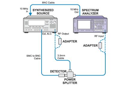
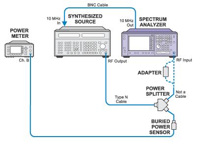
55 Frequency Response (Option B7J) Performance Test Agilent Technologies PSA Series Spectrum Analyzers Test and Adjustment Software Frequency Response (Option B7J) Performance Test NOTE: This test is to be performed on PSA analyzers with Option B7J only. The PSA Option B7J is hardware which supports the Digital Comms options. An electronic attenuator is included in the option. The attenuator realizes 40 db of attenuation with 1, 2, 2, 5, 10, and 20 db steps. The PSA Option B7J Flatness Test measures the flatness of each attenuator section relative to the reference frequency of 50 MHz. The test levels the signal source output by employing a power splitter and a power meter. Measurement uncertainties are kept to a minimum by using a reference sensor to calibrate a buried sensor. The buried sensor calibration calibrates out errors such as output tracking of the splitter. Required Test Equipment Test Equipment Model Number E4440A E4443A, E4445A E4446A E4448A Signal Generator 8665B X X (1 of 3) [5/29/2003 8:47:18 AM]
56 Frequency Response (Option B7J) Performance Test Power Meter E4419A/B X X Power Sensor (2 required) 8482A Option H84 X X Power Splitter 11667A X X Type N Cable 11500C X X Type N (m) to Type N (m) adapter X X Type N (m) to 3.5 mm (f) adapter X 2.4 mm (f) to Type N (m) adapter 11903D X Power Meter Calibration (Channel A) Power Meter Calibration (Channel B) Buried Sensor Transfer Calibration (2 of 3) [5/29/2003 8:47:18 AM]
57 Frequency Response (Option B7J) Performance Test Frequency Response (Option B7J) Test Setup Troubleshooting (3 of 3) [5/29/2003 8:47:18 AM]
58 Frequency Response 300 khz to 3 GHz Performance Test Agilent Technologies PSA Series Spectrum Analyzers Test and Adjustment Software Frequency Response 300 khz to 3 GHz Performance Test Frequency Response (or flatness) is defined as the amplitude deviation from the reference value at 50 MHz. The complete E444XA Frequency Response is measured with three different tests; Frequency Response Below 300 khz Frequency Response 300 khz to 3 GHz Frequency Response Above 3 GHz The Frequency Response Below 300 khz test is used to verify flatness from 10 Hz to 300 khz. The 300 khz normalized error from the Frequency Response 300 khz to 3 GHz test is used as the reference point for the Frequency Response Below 300 khz test. The Frequency Response Above 3 GHz test verifies flatness from 3.0 GHz up to 50 GHz, depending on your instrument frequency range. This test measures Frequency Response 300 khz to 3.0 GHz with the preamplifier (Option 1DS) off and on, in AC coupled mode, and with 10, 20, 30, and 40 db of attenuation. For each test frequency, the amplitude error is normalized to 50 MHz, and the result is called Frequency Response. This test has three sections. The first section measures the flatness from 300 khz to 3 GHz (1 of 5) [5/29/2003 8:47:20 AM]
59 Frequency Response 300 khz to 3 GHz Performance Test with the preamplifier turned off and 10 db of RF attenuation. This section will characterize the tracking error of the 11667A power splitter in order to reduce measurement uncertainties. The second section measures flatness from 50 MHz to 3 GHz with 20, 30, and 40 db of RF attenuation (preamplifier is off). This section is performed on instruments with Serial Number Prefixes greater than US4140, or MY4140. As with the first section, the splitter tracking will be characterized in an effort to reduce the measurement uncertainties. The third section measures flatness from 300 khz to 3 GHz with the preamplifier turned on. As with the first section, the splitter tracking will be characterized in an effort to reduce the measurement uncertainties. Required Test Equipment Test Equipment Model Number E4440A E4443A, E4445A E4446A E4448A Signal Generator 8665B X X Power Meter E4419A/B X X Power Sensor (2 required) 8482A Opt H84 X X 20 db Attenuator 8491A/B Opt 020 (Opt 1DS only) (Opt 1DS only) Power Splitter 11667A X X Type N Cable 11500C X X BNC Cable 10503A X X Type N (m) to Type N (m) adapter X Type N (m) to 3.5 mm (f) adapter Opt BAB 2.4 mm (f) to Type N (m) adapter 11903D X Power Meter Calibration (Channel A) (2 of 5) [5/29/2003 8:47:20 AM]
60 Frequency Response 300 khz to 3 GHz Performance Test Power Meter Calibration (Channel B) 300 khz to 3 GHz Splitter Calibration 300 khz to 3 GHz Flatness Test Setup (3 of 5) [5/29/2003 8:47:20 AM]
 http://mktwww.soco.agilent.com/field/lp/psa/psacalswwebhelp/performance/freqresmidf.")
61 Frequency Response 300 khz to 3 GHz Performance Test 300 khz to 3 GHz Splitter Calibration (Preamp on, Opt 1DS only) 300 khz to 3 GHz Flatness Test Setup (Preamp on, Opt 1DS only) (4 of 5) [5/29/2003 8:47:20 AM]

62 Frequency Response 300 khz to 3 GHz Performance Test Troubleshooting (5 of 5) [5/29/2003 8:47:20 AM]
63 Frequency Response Above 3 GHz Performance Test Agilent Technologies PSA Series Spectrum Analyzers Test and Adjustment Software Frequency Response Above 3 GHz Performance Test Frequency Response (or flatness) is defined as the amplitude deviation from the reference value at 50 MHz. The complete E444XA Frequency Response is measured with three different tests; Frequency Response Below 300 khz Frequency Response 300 khz to 3 GHz Frequency Response Above 3 GHz The Frequency Response Below 300 khz test is used to verify flatness from 10 Hz to 300 khz. The 300 khz normalized error from the Frequency Response 300 khz to 3 GHz test is used as the reference point for the Frequency Response Below 300 khz test. The Frequency Response Above 3 GHz test verifies flatness from 3.0 GHz up to 50 GHz, depending on your instrument frequency range. This test verifies the displayed amplitude vs. frequency over the frequency range from 3.0 GHz to 50 GHz. For each test frequency, the amplitude error is normalized to 50 MHz, and the result is called Frequency Response. Two sources, and two sets of power sensors are used to provide the needed frequency range. The E444XA flatness corrections are located every 100 MHz for frequencies above 3 GHz. (1 of 3) [5/29/2003 8:47:21 AM]
64 Frequency Response Above 3 GHz Performance Test Above 3 GHz the flatness specification widens out such that higher uncertainties can be tolerated, therefore a splitter calibration is not necessary. Required Test Equipment Test Equipment Model Number E4440A E4443A, E4445A E4446A E4448A Synthesized Sweeper 83630A/B 83640A/B, 83650A/B X Synthesized Sweeper 83640A/B, 83650A/B X Power Meter E4419A/B X X Power Sensor 8485A X Power Sensor 8487A X Power Splitter 11667B X Power Splitter 11667C X 3.5 mm Cable X BNC Cable 10503A X X 2.4 mm Cable X 2.4 mm (f) to 3.5 mm (f) adapter 11901B X Type N (m) to 3.5 mm (m) adapter X 3.5 mm (f) to 3.5 mm (f) adapter 83059B X Type N (m) to 2.4 mm (f) adapter 11903D X Power Meter Calibration (Channel A) (2 of 3) [5/29/2003 8:47:21 AM]
65 Frequency Response Above 3 GHz Performance Test Power Meter Calibration (Channel B) Frequency Response Above 3 GHz Test Setup Troubleshooting (3 of 3) [5/29/2003 8:47:21 AM]
66 Frequency Response Below 300 khz Performance Test Agilent Technologies PSA Series Spectrum Analyzers Test and Adjustment Software Frequency Response Below 300 khz Performance Test NOTE: The test Frequency Response 300 khz to 3 GHz must be performed before performing this test. Frequency Response (or flatness) is defined as the amplitude deviation from the reference value at 50 MHz. The complete E444XA Frequency Response is measured with three different tests; Frequency Response Below 300 khz Frequency Response 300 khz to 3 GHz Frequency Response Above 3 GHz The Frequency Response Below 300 khz test is used to verify flatness from 10 Hz to 300 khz. The 300 khz normalized error from the Frequency Response 300 khz to 3 GHz test is used as the reference point for the Frequency Response Below 300 khz test. The Frequency Response Above 3 GHz test verifies flatness from 3.0 GHz up to 50 GHz, depending on your instrument frequency range. This test measures the E444XA flatness over the frequency range from 10 Hz to 300 khz, (1 of 3) [5/29/2003 8:47:22 AM]
67 Frequency Response Below 300 khz Performance Test relative to the amplitude at 300 khz. This relative flatness is converted to an absolute flatness by adding the 300 khz flatness error from the Frequency Response (300 khz to 3 GHz) test. A function generator, and a multimeter are used in the test. The function generator and DVM provide an accurate, flat CW level of V (RMS) (-10 dbm into 50 ohms) to the E444XA. This is the same input level that is used in the 300 khz to 3 GHz test. The E444XA measures the amplitude of the signal in dbm. Flatness (frequency response) is defined as the difference between the multimeter reading and the E444XA reading in db. The E444XA has three flatness correction points below 300 khz. The correction points are 9 khz, 50 khz, and 200 khz. The firmware applies the 9 khz Flatness Correction as an offset to all points below 9 khz. Required Test Equipment Test Equipment Model Number E4440A E4443A, E4445A E4446A E4448A Function Generator 33120A X X Multimeter 3458A X X BNC Cable (2 required) 10503A X X Type N (m) to BNC (f) adapter X X BNC (f) to dual banana adapter X X BNC Tee X X Type N (f) to 3.5 mm (f) adapter (Option BAB) Type N (f) to 2.4mm (f) adapter 11903B X BNC 50 ohm termination X X Frequency Response Below 300 khz System Calibration (2 of 3) [5/29/2003 8:47:22 AM]
68 Frequency Response Below 300 khz Performance Test Frequency Response Below 300 khz Test Setup Troubleshooting (3 of 3) [5/29/2003 8:47:22 AM]
69 PSA Memory Initialization Utility Agilent Technologies PSA Series Spectrum Analyzers Test and Adjustment Software Memory Initialization Utilities The PSA Memory Initialization Utilities encompass two functions. One utility resets the statistics (attenuator actuations, 50 MHz calibrator actuations, temperature ranges, hours of operation, etc.). The other writes the latest default calibration constants into the memory of a particular board assembly. This is needed since one part number board assembly is used in several model numbers, and certain model numbers require different default calibration constants. Utilities are selected the same way as performance tests and adjustments. Utility 1: Modification of Hardware Statistical Data Utility 1 resets the statistical data (attenuator actuations, 50 MHz calibrator switches, hours of operation, etc.) on the A12 assembly. This statistical information is viewed on the analyzer screen when you press: System, More, Show System. It is to be used to reset one of the fields for troubleshooting, or due to an assembly replacement. For example, the number of preamplifier switch actuations will need to be reset to zero if the preamplifier is replaced. When used: After replacing either of the attenuators or the preamp, or if you want to reset the temperature extremes the instrument encounters or the auto align Off time. The utility will: (1 of 2) [5/29/2003 8:47:23 AM]
70 PSA Memory Initialization Utility Reset mechanical attenuator actuations when either the A14 or A15 Input Attenuators are replaced. Reset 50 MHz switch actuations when the A14 Input Attenuator is replaced. Reset AC/DC switch actuations when the A14 Input Attenuator is replaced. Reset Preamp switch actuations when the A22 Preamp is replaced. Reset the temperature extremes. You may wish to reset this counter when troubleshooting temperature related problems. Reset the Auto Align OFF time. You can turn the Auto align function off so an auto align will not occur during a critical test. This counter keeps track of the time in hours that auto align is turned off. Being able to reset this allows you to restart the clock if you wish. Reset Overload Events. You may wish to reset this when troubleshooting input power related problems. Utility 2: Calibration Constant Memory Initialization Utility 2 supports four board assemblies that can be configured via memory initialization to work in a particular instrument model. Eight variations are needed to initialize the memory on the current instruments. The 3rd Converter, Analog IF, and LO/Synthesizer assemblies need to be configured either for the E4440A/E4443A/E4445A or for the E4446A/E4448A. The Front End Driver assembly needs to be configured differently for either the E4446A or E4448A. When used: After replacing the following board assemblies. A8 Analog IF A10 3rd Converter A12A1 Synthesizer Board or entire A12 Synthesizer Assembly A13 Front End Driver (E4446A or E4448A) (2 of 2) [5/29/2003 8:47:23 AM]
71 PSA Adjustments Agilent Technologies PSA Series Spectrum Analyzers Test and Adjustment Software PSA Series Adjustments The following adjustments can be performed on the PSA series spectrum analyzers. These procedures are designed to reset various circuit parameters or recalculate correction values associated with some measurements. The software is designed to adjust an instrument operating within the operational temperature range defined by the instrument specifications. Never perform adjustments as routine maintenance. Adjustments should be performed only after a repair or a performance test failure. 1. Lowband Mixer Bias Adjustment 2. SLODA Adjustment (E4440A, E4443A, E4445A) 3. FELOMA Adjustment (E4446A, E4448A) 4. Second LO Power Adjustment 5. Analog IF Input Detector Adjustment 6. Attenuator Slope Adjustment MHz Calibrator Amplitude Adjustment 8. Overload Detector DAC Adjustment MHz Internal Frequency Reference Adjustment 10. YTF Alignment Adjustment 11. Frequency Response Adjustment (1 of 2) [5/29/2003 8:47:24 AM]
72 PSA Adjustments 12. Frequency Response Adjustment (Option B7J) Memory Initialization Utilities (2 of 2) [5/29/2003 8:47:24 AM]
73 Lowband Mixer Bias Adjustment Agilent Technologies PSA Series Spectrum Analyzers Test and Adjustment Software Lowband Mixer Bias Adjustment The bias currents for the A20 Lowband (1 st and 2 nd mixer) internal amplifiers are adjusted. These are for the 1 st mixer LO amplifier and IF amplifier, and for the 2 nd mixer LO amplifier. The currents are set by measuring voltage differences across 1 ohm sense resistors. Voltages are monitored on test points on the A13 Front End Driver with a DVM and are adjusted by supplying data to DACs on A13. The test points are accessible via a header on the top of A13, so placing A13 on an extender is not necessary. The instrument cover and top shield must be removed, however. This adjustment should be performed after replacing the A20 and/or A13 assemblies. Required Test Equipment Test Equipment Model Number E4440A E4443A, E4445A E4446A E4448A Digital Voltmeter 3458A X X E Bias Adjustment Board X X DC Probe 11002A, 11003A X X Lowband Mixer Bias Adjustment Setup (1 of 2) [5/29/2003 8:47:24 AM]
74 Lowband Mixer Bias Adjustment (2 of 2) [5/29/2003 8:47:24 AM]
75 Switched LO Distribution Amplifier (SLODA) Adjustment (E4440A, E4443A, E4445A) Agilent Technologies PSA Series Spectrum Analyzers Test and Adjustment Software Switched LO Distribution Amplifier (SLODA) Adjustment (E4440A, E4443A, E4445A) The Switched LO Distribution Amplifier (SLODA) requires six ALC bias voltages and one gate bias. The voltages for each of these biases are printed on the SLODA label. These voltages can be read with a DVM on the test connector on the Front End Driver, A13J12. The computer sends commands to the PSA to set the appropriate latch and bias DAC, and the DVM is used to verify that the proper bias voltages are present. This adjustment should be performed after replacing the A21 or A13 assemblies. Required Test Equipment Test Equipment Model Number Digital Voltmeter 3458A E Bias Adjustment Board DC Probe 11002A, 11003A (1 of 2) [5/29/2003 8:47:25 AM]

76 Switched LO Distribution Amplifier (SLODA) Adjustment (E4440A, E4443A, E4445A) SLODA Adjustment Setup (2 of 2) [5/29/2003 8:47:25 AM]
77 Frequency Extended Local Oscillator Multiplier Amplifier (FELOMA) Amplifier Adjustment (E4446A, E4448A) Agilent Technologies PSA Series Spectrum Analyzers Test and Adjustment Software Frequency Extended Local Oscillator Multiplier Amplifier (FELOMA) Adjustment (E4446A, E4448A) The Frequency Extended Local Oscillator Multiplier Amplifier (FELOMA) provides amplitude leveling and distribution of the first LO (3 to 7 GHz) to the Lowband assembly, RYTHM, SBTX, and the LO Synthesizer assembly. There are three ALC loops in the FELOMA. The main input ALC loop can have its sense voltage come from either the RYTHM/Lowband path or the Front Panel External LO out path. The 2nd ALC loop is used to level the power going into the sampler. The 3rd ALC loop is for the SBTX output. The SBTX output frequency is twice that of the LO. The FELOMA requires eleven level adjustments and four bias adjustments. The voltages for each of these adjustments are printed on the FELOMA level. The voltages are measured with a DVM which is connected to a board attached to the Front End Driver A13J12 connector. This adjustment should be performed after replacing the A21 or A13 assemblies. (1 of 2) [5/29/2003 8:47:26 AM]

78 Frequency Extended Local Oscillator Multiplier Amplifier (FELOMA) Amplifier Adjustment (E4446A, E4448A) Required Test Equipment Test Equipment Model Number Digital Voltmeter 3458A E Bias Adjustment Board FELOMA Adjustment Setup FELOMA Label Locations (2 of 2) [5/29/2003 8:47:26 AM]
79 Second LO Power Adjustment Agilent Technologies PSA Series Spectrum Analyzers Test and Adjustment Software Second LO Power Adjustment The 3.6 GHz 2 nd LO Power is measured with a power meter at the A20 Lowband 2 nd LO Test Port, A20J6. The power is controlled by a DAC on the A13 Front End Driver. The computer reads the power and adjusts the DAC for the proper level. The instrument cover and top shield must be removed to access the LO Test Port, but it is not necessary to put PC assemblies on extenders. The instrument internally reads the power level with a detector and ADC. This is done to keep the power level constant with changing temperature. The adjustment stores a value in the FE Driver EEROM used to calibrate the ADC so that the value corresponds to the proper power level. The 2 nd LO Power needs to be adjusted from a conservatively low level, and then gradually increased to the proper level in order to avoid saturating the 2 nd LO amplifiers. This adjustment should be performed after replacing the A20 and/or A13 assemblies. Required Test Equipment (1 of 3) [5/29/2003 8:47:28 AM]
 adapter 1250-1750 X X Power Meter Calibration Second LO Power Adjustment Setup A20J5 http://mktwww.soco.agilent.com/field/lp/psa/psacalswwebhelp/adjustment/adjust2lopow.")
80 Second LO Power Adjustment Test Equipment Model Number E4440A E4443A, E4445A E4446A E4448A Power Meter E4419A/B X X Power Sensor 8481A X X Type N (f) to 3.5 mm (m) adapter X X Power Meter Calibration Second LO Power Adjustment Setup A20J5 (2 of 3) [5/29/2003 8:47:28 AM]

81 Second LO Power Adjustment (3 of 3) [5/29/2003 8:47:28 AM]
82 Analog IF Input Detector Adjustment Agilent Technologies PSA Series Spectrum Analyzers Test and Adjustment Software Analog IF Input Detector Adjustment The adjustment determines the power detected by the A8 Analog IF (AIF) input power detector under known conditions. The detector gives a DC level which corresponds to this power. An ADC converts this DC level to a digital value which is then stored in the A8 EEPROM. The MHz calibrator on the A10 Third Converter is used to provide a stable -7 dbm, 21.4 MHz signal to the A8 input. A power meter is used to measure this signal at A10J5 to accurately set its power level. This adjustment should be performed after replacing the A8 assembly. Required Test Equipment Test Equipment Model Number E4440A E4443A, E4445A E4446A E4448A Power Meter E4419A/B X X Power Sensor 8481A X X Type N (f) to BNC (m) adapter , X X SMB (f) to BNC (f) adapter X X (1 of 2) [5/29/2003 8:47:29 AM]
83 Analog IF Input Detector Adjustment Power Meter Calibration Analog IF Input Detector Adjustment Setup (2 of 2) [5/29/2003 8:47:29 AM]
84 Attenuator Slope Adjustment Agilent Technologies PSA Series Spectrum Analyzers Test and Adjustment Software Attenuator Slope Adjustment The slopes for each attenuator setting in DC Coupled mode, and in the 10 db AC Coupled mode, are calculated and are stored in an array in EEROM on the A13 Front End Driver assembly. The test is performed at 50 MHz, 2.8 GHz, 6 GHz, 10 GHz, 15 GHz, and 20 GHz for the E4440A, up through 10 GHz for E4445A, up through 6 GHz for E4443A, and up through 40 GHz for E4446A/E4448A. At each test frequency, source power level is set so that the power meter reads -10 dbm with the PSA set at 10 db, DC Coupled attenuation. This value is then used as the reference for the other attenuator states at that frequency. Instrument covers do not need to be removed for this adjustment. Also, this adjustment must only be performed if the PSA has valid flatness correction data. This adjustment should be performed after replacing the A13 Front End Driver, or after replacing the A14 and/or A15 step attenuators. Required Test Equipment Test Equipment Model Number E4440A E4443A, E4445A E4446A E4448A (1 of 3) [5/29/2003 8:47:30 AM]
85 Attenuator Slope Adjustment Synthesized Sweeper 83630A/B 83640A/B, 83650A/B X Synthesized Sweeper 83640A/B, 83650A/B X Power Meter E4419A/B X X Power Sensor 8485A X Power Sensor 8487A X Power Splitter 11667C X Power Splitter 11667B X BNC Cable 10503A X X 2.4 mm Cable X 3.5 mm Cable X 3.5 mm (f) to 3.5 mm (f) adapter 83059B X Type N (m) to 3.5 mm (m) adapter X 2.4 mm (f) to 3.5 mm (f) adapter 11901B X 2.4 mm (f) to Type N (m) adapter 11903D X Power Meter Calibration Attenuator Slope Adjustment Setup (2 of 3) [5/29/2003 8:47:30 AM]

86 Attenuator Slope Adjustment (3 of 3) [5/29/2003 8:47:30 AM]
87 50 MHz Calibrator Amplitude Adjustment Agilent Technologies PSA Series Spectrum Analyzers Test and Adjustment Software 50 MHz Calibrator Amplitude Adjustment An RF substitution method is made using the 50 MHz, -25 dbm calibrator Z5602A. The level of the calibrator is read by the PSA and then the PSA s internal 50 MHz calibrator is measured. The difference is stored in memory as a correction. Required Test Equipment Test Equipment 50 MHz Calibrator Model Number Z5602A 0ption 51 (Opt H35 for BAB Opt H24 for E4446A, E4448A) E4440A E4443A, E4445A X E4446A E4448A X 50 MHz Calibrator Amplitude Adjustment Setup (1 of 2) [5/29/2003 8:47:31 AM]

88 50 MHz Calibrator Amplitude Adjustment (2 of 2) [5/29/2003 8:47:31 AM]
89 Overload Detector DAC Adjustment Agilent Technologies PSA Series Spectrum Analyzers Test and Adjustment Software Overload Detector DAC Adjustment The overload detector is in the first IF in the A20 Low Band. It is used as a warning when a high input level outside the viewing span is compressing the first mixer. It can also be used as a diagnostic tool. This adjustment should be performed after replacing the A20 assembly. Required Test Equipment Test Equipment Model Number E4440A E4443A, E4445A E4446A E4448A Signal Generator E4433B X X Type N Cable 11500C X X Type N (f) to 3.5 mm (f) adapter Opt BAB 2.4 mm (f) to Type N (f) adapter 11903B X Overload Detector DAC Adjustment Setup (1 of 2) [5/29/2003 8:47:32 AM]

90 Overload Detector DAC Adjustment (2 of 2) [5/29/2003 8:47:32 AM]
91 10 MHz Internal Frequency Reference Adjustment Agilent Technologies PSA Series Spectrum Analyzers Test and Adjustment Software 10 MHz Internal Frequency Reference Adjustment This procedure adjusts the 10 MHz internal frequency reference within minimal variance. This adjustment is generally done after the results from the Internal Frequency Reference Performance Test indicate that it is time for an adjustment. In this test the signal from a 10 MHz frequency standard is inserted into the RF input of the PSA. The instrument s internal timebase is then adjusted by programming its DAC and doing a marker count on the displayed signal. The specification for the 10 MHz reference accuracy is ± [(Time Since Last Adjustment x 1x10⁻⁷ ) + (Temperature Stability) + (Achievable Initial Calibration Accuracy)]. With this adjustment the first term is zero. At 20 to 30 C the rest of the specification comes to ±0.8 Hz. The objective of this procedure is to bring the reference to within 0.1 Hz of 10 MHz. Note: A minimum warm-up time of 24 hours is required for minimal frequency reference drift. Required Test Equipment (1 of 2) [5/29/2003 8:47:33 AM]
 to BNC (m) adapter 1250-1477, 1250-0077 X X Type N (f) to 3.5 mm (f) adapter 1250-1745 Opt BAB 2.")
92 10 MHz Internal Frequency Reference Adjustment Test Equipment Model Number E4440A E4443A, E4445A E4446A E4448A Frequency Standard 5071A X X 20 db Fixed Attenuator 8491A/ Option 020 X X Type N Cable 11500C X X Type N (f) to BNC (m) adapter , X X Type N (f) to 3.5 mm (f) adapter Opt BAB 2.4 mm (f) to Type N (f) adapter 11903B X 10 MHz Internal Frequency Reference Adjustment Setup (2 of 2) [5/29/2003 8:47:33 AM]
93 YTF Alignment (RYTHM and SBTX) Agilent Technologies PSA Series Spectrum Analyzers Test and Adjustment Software YTF Alignment (RYTHM and SBTX) The instrument firmware tunes the YTF (Yig Tunable Filter) via a DAC. The relationship between DAC value and tuned center frequency follows a 3rd order polynomial curve. The non-linearity of this curve is enough to offset the center frequency of this filter by several tens of MHz. This alignment calculates the coefficients of the 3rd order polynomial. The RYTHM YTF tunable range (2.85 GHz to 26.5GHz) is split into two different regions: Band (2.85 GHz to 19.2 GHz) and Band 4 (18.7 GHz to 26.5 GHz). The SBTX YTF frequency range is separated into band 5 (26.4 GHz to GHz) and band 6 (31 GHz to 50 GHz). For each freq: The DUT is tuned to the desired Cal Freq. The YTF center freq is found using a SW controlled preselector center routine. The YTF center amplitude is found during the fine adjust. The associated Start Tune Dac number is found. Required Test Equipment (1 of 3) [5/29/2003 8:47:34 AM]
94 YTF Alignment (RYTHM and SBTX) Test Equipment Model Number E4440A E4443A, E4445A E4446A E4448A Synthesized Sweeper 83630A/B 83640A/B, 83650A/B X Synthesized Sweeper 83640A/B, 83650A/B X Power Meter E4419A/B X X Power Sensor 8485A X Power Sensor 8487A X Power Splitter 11667B X Power Splitter 11667C X 3.5 mm Cable X 2.4 mm Cable X BNC Cable 10503A X X 3.5 mm (f) to 2.4 mm (f) adapter 11901B X X Type N (m) to 3.5 mm (m) adapter X Power Meter Calibration YTF Alignment Setup (2 of 3) [5/29/2003 8:47:34 AM]

95 YTF Alignment (RYTHM and SBTX) (3 of 3) [5/29/2003 8:47:34 AM]
96 Frequency Response Adjustment Agilent Technologies PSA Series Spectrum Analyzers Test and Adjustment Software Frequency Response Adjustment This adjustment procedure performs the following steps: The instrument s internal flatness corrections are turned off. Amplitude error as a function of frequency from 9 khz to 26.5 GHz is measured and normalized to the 50 MHz measurement. Predetermined frequency points are used when testing from 9 khz to 50 MHz and 3 GHz to 26.5 GHz. Frequency points tested from 50 MHz to 3 GHz are determined by the Adaptive Flatness procedure. The Adaptive Flatness procedure gathers a custom list of the most critical frequency points for each instrument. At each frequency the source amplitude is adjusted to keep the power constant as measured by a power meter connected to the power splitter. Special note for E4443A and E4445A instruments: Since these instruments have max frequency limits that line up near the band breaks of the 26.5 GHz E4440A, it is necessary to gather a few correction points in the next higher band. This allows the instrument to tune a center screen signal at the instrument s specified max frequency and still be able to sweep 400 MHz past the signal. For example, the 6.7 GHz E4443A will have correction values gathered from 6.2 GHz to 7.1 GHz in Band 2. This is not only necessary to sweep past a 6.7 MHz center screen signal, but also, Band 1 ends at 6.6 GHz, not 6.7 GHz. If the instrument contains Option 1DS, 500 khz to 3 MHz preamplifier, additional testing is performed with the preamp turned on. (1 of 11) [5/29/2003 8:47:37 AM]
97 Frequency Response Adjustment Two sources, and two sets of power sensors are used to provide the needed frequency range. To measure frequencies below 100 khz, a DVM with a 50 ohm load replaces the power sensor and a function generator is used as the source. For improved amplitude accuracy below 3 GHz, the power splitter is characterized using a specially-calibrated power sensor (the reference sensor) connected to one power splitter output port. The other power splitter output port connects to the buried sensor; it is not removed from the power splitter. Once the characterization is done, the reference sensor is removed and replaced by the PSA. Before testing frequencies >3 GHz, measurements are made at several frequencies in bands 1 through 4, as applicable, to determine a target power level. The target power level is the highest power level measured at the PSA that allows the synthesized sweeper output to remain leveled. The ideal target power level is 10 dbm, but levels as low as 20 dbm may be used. Uncorrected flatness data is collected for each state. This is the raw frequency response data. The uncorrected flatness data is normalized to the 50 MHz reference measurement taken in each state. Further processing manipulates the uncorrected data so all states are measured relative to the 10 db input atten, preamp off, DC coupled reference. The corrections are stored in the Front End Driver EEPROM as frequency/amplitude pairs under unique File ID numbers. The related performance test for this adjustment is Frequency Response. Required Test Equipment Test Equipment Model Number E4440A E4443A, E4445A E4446A E4448A Synthesized Sweeper 83630A/B 83640A/B, 83650A/B X Synthesized Sweeper 83640A/B, 83650A/B X Function Generator 33120A X X Multimeter 3458A X X (2 of 11) [5/29/2003 8:47:37 AM]
98 Frequency Response Adjustment Power Meter E4419A/B X X Power Sensor (2 required) 8482A X X Power Sensor 8485A X Power Sensor 8487A X Power Splitter 11667A X X Power Splitter 11667B X Power Splitter 11667C X 50 ohm Termination X X 20 db Attenuator 8491A Option 020 X X 20 db Attenuator 8493C X X 3.5 mm Cable X X 2.4 mm Cable X BNC Cable (3 required) 10503A X X BNC (m) to SMC (f) Cable X X Type N (m) to 3.5 mm (m) adapter X Type N (f) to 3.5 mm (f) adapter X Type N (m) to 3.5 mm (f) adapter (2 required) X BNC (f) to SMA (m) adapter X X Dual Banana to BNC (f) adapter X X BNC Tee (f, m, f) X X Type N (m) to BNC (f) adapter X X Type N (m) to Type N (m) adapter X X 3.5 mm (f) to 3.5 mm (f) adapter 83059B X 3.5 mm (f) to 2.4 mm (f) adapter 11901B X X 2.4 mm (f) to 3.5 mm (m) adapter 11901D X Detector 33330C X 1 As an alternative to this cable you can use a 10503A BNC cable with a BNC to SMC adapter. 10 MHz Reference Connections (3 of 11) [5/29/2003 8:47:37 AM]

99 Frequency Response Adjustment Adaptive Flatness Adaptive Flatness (Preamp on, Opt. 1DS only) (4 of 11) [5/29/2003 8:47:37 AM]
100 Frequency Response Adjustment Power Meter Calibration (Channel A) Power Meter Calibration (Channel B) (5 of 11) [5/29/2003 8:47:37 AM]
 Splitter Calibration, Step 2 Frequency Response")

101 Frequency Response Adjustment Frequency Response Adjustment (100 khz to 3 GHz) Splitter Calibration, Step 1 Frequency Response Adjustment (100 khz to 3 GHz) Splitter Calibration, Step 2 Frequency Response Adjustment (100 khz to 3 GHz) Splitter Calibration, Step 1 (Preamp on, Opt. 1DS only) (6 of 11) [5/29/2003 8:47:37 AM]


102 Frequency Response Adjustment Frequency Response Adjustment (100 khz to 3 GHz) Splitter Calibration, Step 2 (Preamp on, Opt. 1DS only) Frequency Response Adjustment (100 khz to 3 GHz) Setup, Step 1 (7 of 11) [5/29/2003 8:47:37 AM]

103 Frequency Response Adjustment Frequency Response Adjustment (100 khz to 3 GHz) Setup, Step 2 (8 of 11) [5/29/2003 8:47:37 AM]
 Frequency Response Adjustment (100 khz to 3 GHz) Setup, Step 2 (Preamp on, Opt. 1DS only) http://mktwww.soco.agilent.")
104 Frequency Response Adjustment Frequency Response Adjustment (100 khz to 3 GHz) Setup, Step 1 (Preamp on, Opt. 1DS only) Frequency Response Adjustment (100 khz to 3 GHz) Setup, Step 2 (Preamp on, Opt. 1DS only) (9 of 11) [5/29/2003 8:47:37 AM]
 Setup http://mktwww.soco.agilent.com/field/lp/psa/psacalswwebhelp/adjustment/adjustflatadjstd.")
105 Frequency Response Adjustment Frequency Response Adjustment (< 100 khz) System Calibration Frequency Response Adjustment (< 100 khz) Setup (10 of 11) [5/29/2003 8:47:37 AM]
106 Frequency Response Adjustment Frequency Response Adjustment (Bands 1 through 4) Setup (11 of 11) [5/29/2003 8:47:37 AM]
107 Frequency Response Adjustment (Option B7J) Agilent Technologies PSA Series Spectrum Analyzers Test and Adjustment Software Frequency Response Adjustment (Option B7J) The E4440A Option B7J is a Digital Modulation Demodulation option. An electric attenuator is included in the option. The E4440A Electronic Attenuator contains six attenuator sections. The sections are 1, 2, 2, 5, 10, and 20 db steps. A maximum of 40 db attenuation can be realized with these six sections. The E4440A Electronic Attenuator Flatness is corrected with 101 data points from 1 MHz to 3 GHz. These correction points are not evenly spaced across the 1 MHz to 3 GHz band. The points are spaced in 15 MHz intervals in the Comms bands, and 50 MHz intervals outside the Comms bands. The same correction points are used for each of the 41 attenuator steps. Required Test Equipment Test Equipment Model Number E4440A E4443A, E4445A E4446A E4448A Signal Generator 8665B X X Power Meter E4419A/B X X Power Sensor (2 required) 8482A X X Power Splitter 11667A X X (1 of 3) [5/29/2003 8:47:38 AM]
108 Frequency Response Adjustment (Option B7J) Type N Cable 11500C X X BNC Cable 10503A X X Type N (m) to Type N (m) adapter X X Type N (m) to 3.5 mm (f) adapter Opt BAB 2.4 mm (f) to Type N (m) adapter 11903D X Power Meter Calibration (Channel A) Power Meter Calibration (Channel B) Frequency Response Adjustment (Option B7J) Splitter Calibration (2 of 3) [5/29/2003 8:47:38 AM]
 Setup http://mktwww.")
109 Frequency Response Adjustment (Option B7J) Frequency Response Adjustment (Option B7J) Setup (3 of 3) [5/29/2003 8:47:38 AM]
Agilent ESA-L Series Spectrum Analyzers
 Agilent ESA-L Series Spectrum Analyzers Data Sheet Available frequency ranges E4403B E4408B 9 khz to 1.5 GHz 9 khz to 3.0 GHz 9 khz to 26.5 GHz As the lowest cost ESA option, these basic analyzers are
Agilent X-Series Signal Analyzer This manual provides documentation for the following X-Series Analyzer: CXA Signal Analyzer N9000A
 Agilent X-Series Signal Analyzer This manual provides documentation for the following X-Series Analyzer: CXA Signal Analyzer N9000A N9000A CXA Functional Tests Notices Agilent Technologies, Inc. 2006-2008
Specification RIGOL. 6 Specification
 Specification RIGOL 6 Specification This chapter lists the specifications and general specifications of the analyzer. All the specifications are guaranteed when the following conditions are met unless
DSA700 Series Spectrum Analyzer
 DSA700 Series Spectrum Analyzer Product Features: All-Digital IF Technology Frequency Range from 100 khz up to 1 GHz Min. -155 dbm Displayed Average Noise Level (Typ.) Min.
Contents. CALIBRATION PROCEDURE NI PXIe GHz and 14 GHz RF Vector Signal Analyzer
 CALIBRATION PROCEDURE NI PXIe-5665 3.6 GHz and 14 GHz RF Vector Signal Analyzer This document contains the verification procedures for the National Instruments PXIe-5665 (NI 5665) RF vector signal analyzer
Chapter 5 Specifications
 RIGOL Specifications are valid under the following conditions: the instrument is within the calibration period, is stored for at least two hours at 0 to 50 temperature and is warmed up for 40 minutes.
Contents. CALIBRATION PROCEDURE NI PXIe-5668R 14 GHz and 26.5 GHz Signal Analyzer
 CALIBRATION PROCEDURE NI PXIe-5668R 14 GHz and 26.5 GHz Signal Analyzer This document contains the verification procedures for the National Instruments PXIe-5668R (NI 5668R) vector signal analyzer (VSA)
DSA800. No.1 RIGOL TECHNOLOGIES, INC.
 No.1 DSA800 9 khz to 1.5 GHz Frequency Range Typical -135 dbm Displayed Average Noise Level (DANL) -80 dbc/hz @10 khz offset Phase Noise Total Amplitude Uncertainty
Calibration Guide. 8590L Spectrum Analyzer
 Calibration Guide 8590L Spectrum Analyzer Manufacturing Part Number: 08590-90315 Supersedes: 08590-90269 Printed in USA April 2001 Copyright 1994-1995, 2000-2001 Agilent Technologies, Inc. The information
100 Hz to 22. HP 8566B Spectrum Analyzer. Discontinued Product Support Information Only. Outstanding Precision and Capability
 Discontinued Product Support Information Only This literature was published years prior to the establishment of Agilent Technologies as a company independent from Hewlett-Packard and describes products
Agilent N9320B RF Spectrum Analyzer
 Agilent N9320B RF Spectrum Analyzer 9 khz to 3.0 GHz Data Sheet Definitions and Conditions The spectrum analyzer will meet its specifications when: It is within its calibration cycle It has been turned
Keysight Technologies N9320B RF Spectrum Analyzer
 Keysight Technologies N9320B RF Spectrum Analyzer 9 khz to 3.0 GHz Data Sheet Definitions and Conditions The spectrum analyzer will meet its specifications when: It is within its calibration cycle It has
Agilent 8560 EC Series Spectrum Analyzers Data Sheet
 Agilent 8560 EC Series Spectrum Analyzers Data Sheet Agilent 8560EC 30 Hz to 2.9 GHz Agilent 8561EC 30 Hz to 6.5 GHz 1 Agilent 8562EC 30 Hz to 13.2 GHz Agilent 8563EC 30 Hz to 26.5 GHz Agilent 8564EC 30
PXIe Contents CALIBRATION PROCEDURE. Reconfigurable 6 GHz RF Vector Signal Transceiver with 200 MHz Bandwidth
 IBRATION PROCEDURE PXIe-5646 Reconfigurable 6 GHz Vector Signal Transceiver with 200 MHz Bandwidth This document contains the verification and adjustment procedures for the PXIe-5646 vector signal transceiver.
Spectrum Analyzers 2680 Series Features & benefits
 Data Sheet Features & benefits n Frequency range: 9 khz to 2.1 or 3.2 GHz n High Sensitivity -161 dbm/hz displayed average noise level (DANL) n Low phase noise of -98 dbc/hz @ 10 khz offset n Low level
Agilent ESA-L Series Spectrum Analyzers
 Agilent ESA-L Series Spectrum Analyzers Product Overview When speed and accuracy count as much as your budget Expanded to 3 and 26.5 GHz! 2 Speed, accuracy, affordability High-resolution, high-contrast
PXIe Contents SPECIFICATIONS. 14 GHz and 26.5 GHz Vector Signal Analyzer
 SPECIFICATIONS PXIe-5668 14 GHz and 26.5 GHz Vector Signal Analyzer These specifications apply to the PXIe-5668 (14 GHz) Vector Signal Analyzer and the PXIe-5668 (26.5 GHz) Vector Signal Analyzer with
ESA-E Series Spectrum Analyzer
 ESA-E Series Spectrum Analyzer Data Sheet Available frequency ranges: E4402B 9 khz to 3.0 GHz E4404B 9 khz to 6.7 GHz E4405B 9 khz to 13.2 GHz E4407B 9 khz to 26.5 GHz Table of Contents Definitions of
DSA800. No.2 RIGOL TECHNOLOGIES, INC. All-Digital IF Technology 9 khz GHz Frequency Range
 No.2 DSA800 All-Digital IF Technology 9 khz - 1.5 GHz Frequency Range Up to -135dBm Displayed Average Noise Level (DANL) -80dBc/Hz @ 10kHz Oset Phase Noise Total Amplitude Uncertainty < 1.5dB 100Hz Minimum
khz to 2.9 GHz Spectrum Analyzer
 Spectrum Analyzers 2399 9 khz to 2.9 GHz Spectrum Analyzer A spectrum analyzer with outstanding performance and a user friendly visual interface simplifying many complex measurements. 9 khz to 2.9 GHz
Agilent 8560 E-Series Spectrum Analyzers
 Agilent 8560 E-Series Spectrum Analyzers Data Sheet 8560E 30 Hz to 2.9 GHz 8561E 30 Hz to 6.5 GHz 8562E 30 Hz to 13.2 GHz 8563E 30 Hz to 26.5 GHz 8564E 30 Hz to 40 GHz 8565E 30 Hz to 50 GHz 8565E SPECTRUM
2.9GHz SPECTRUM ANALYZER
 2.9GHz SPECTRUM ANALYZER Introducing a new 2.9GHz Spectrum Analyzer Manufacturing Research and Development Field Service Education Powerful capacity by advanced digital synthesizer Revolutionary features
Test & Calibration Benefits from a New Precision RF/Microwave Calibrator
 Test & Calibration Benefits from a New Precision RF/Microwave Calibrator Topics: RF & Microwave calibration signal requirements Design philosophy and architecture of the new RF Calibrator. Spectrum analyzer
A Guide to Calibrating Your Spectrum Analyzer
 A Guide to Calibrating Your Application Note Introduction As a technician or engineer who works with electronics, you rely on your spectrum analyzer to verify that the devices you design, manufacture,
Keysight Technologies Making Accurate Intermodulation Distortion Measurements with the PNA-X Network Analyzer, 10 MHz to 26.5 GHz
 Keysight Technologies Making Accurate Intermodulation Distortion Measurements with the PNA-X Network Analyzer, 10 MHz to 26.5 GHz Application Note Overview This application note describes accuracy considerations
Site Master Cable and Antenna Analyzer with Spectrum Analyzer
 Maintenance Manual Site Master Cable and Antenna Analyzer with Spectrum Analyzer S331E, 2 MHz to 4 GHz S332E, 2 MHz to 4 GHz, Spectrum Analyzer, 100 khz to 4 GHz S361E, 2 MHz to 6 GHz S362E, 2 MHz to 6
GA GHz. Digital Spectrum Analyzer
 Digital Spectrum Analyzer GA4063 3GHz Professional Performance Robust Measurement features High frequency stability Easy- to-use User Interface Compact size, Light weight, Portable design www.attenelectronics.com
Reconfigurable 6 GHz RF Vector Signal Transceiver with 1 GHz Bandwidth
 CALIBRATION PROCEDURE PXIe-5840 Reconfigurable 6 GHz RF Vector Signal Transceiver with 1 GHz Bandwidth This document contains the verification procedures for the PXIe-5840 vector signal transceiver. Refer
Advanced Test Equipment Rentals ATEC (2832)
") Established 1981 Advanced Test Equipment Rentals www.atecorp.com 800-404-ATEC (2832) Agilent 2-Port and 4-Port PNA-X Network Analyzer N5249A - 10 MHz to 8.5 GHz N5241A - 10 MHz to 13.5 GHz N5242A - 10
Established 1981 Advanced Test Equipment Rentals www.atecorp.com 800-404-ATEC (2832) Agilent 2-Port and 4-Port PNA-X Network Analyzer N5249A - 10 MHz to 8.5 GHz N5241A - 10 MHz to 13.5 GHz N5242A - 10
Spectrum Analyzers. 2394A 1 khz to 13.2 GHz Spectrum Analyzer.
 Spectrum Analyzers 2394A 1 khz to 13.2 GHz Spectrum Analyzer A spectrum analyzer with outstanding performance and a user friendly visual interface simplifying many complex measurements 1 khz to 13.2 GHz
Spectrum Analyzer. Distribution in the UK & Ireland
 DSA800 Series Spectrum Analyzer All-Digital IF Technology Frequency Range from 9 khz up to 7.5 GHz Min. -161dBm Displayed Average Noise Level (Typ.) Min. < -98dBc/Hz @ 10kHz Offset Phase Noise Level Measurement
Agilent E7400A Series EMC Analyzers
 Agilent E7400A Series EMC Analyzers Data Sheet These specifications apply to the Agilent Technologies E7402A and E7405A EMC analyzers. Frequency Specifications Frequency range E7402A dc coupled 100 Hz
DSA800 RIGOL TECHNOLOGIES, INC.
 DSA800 All-Digital IF Technology 9 khz - 1.5 GHz Frequency Range Up to -135dBm Displayed Average Noise Level (DANL) -80dBc/Hz @ 10kHz Oset Phase Noise Total Amplitude Uncertainty < 1.5dB 100Hz Minimum
FREEDOM Communications System Analyzer R8600 DATA SHEET
 FREEDOM Communications System Analyzer R8600 DATA SHEET Table of Contents Operating/Display Modes 3 General 3 Generator (Receiver Test) 4 Receiver (Transmitter Test) 5 Spectrum Analyzer 6 Oscilloscope
Agilent N9343C Handheld Spectrum Analyzer (HSA)
") Test Equipment Depot - 800.517.8431-99 Washington Street Melrose, MA 02176 - TestEquipmentDepot.com Agilent N9343C Handheld Spectrum Analyzer (HSA) 1 MHz to 13.6 GHz (tunable to 9 khz) Data Sheet Field
Test Equipment Depot - 800.517.8431-99 Washington Street Melrose, MA 02176 - TestEquipmentDepot.com Agilent N9343C Handheld Spectrum Analyzer (HSA) 1 MHz to 13.6 GHz (tunable to 9 khz) Data Sheet Field
FREEDOM Communications System Analyzer R8000C DATA SHEET
 FREEDOM Communications System Analyzer R8000C DATA SHEET Table of Contents Operating/Display Modes 3 General 3 Generator (Receiver Test) 4 Receiver (Transmitter Test) 5 Spectrum Analyzer 6 Oscilloscope
GA GHz. Digital Spectrum Analyzer
 Digital Spectrum Analyzer GA4063 3GHz Professional Performance Robust Measurement features High frequency stability Easy- to-use User Interface Compact size, Light weight, Portable design www.attenelectronics.com
Agilent CSA Spectrum Analyzer
 Agilent CSA Spectrum Analyzer N1996A Exceptional performance... anytime, anywhere Frequency coverage Frequency range: 100 khz to 3 or 6 GHz Signal source: 10 MHz to 3 or 6 GHz Preamplifier to 3 or 6 GHz
FREEDOM Communications System Analyzer R8100 DATA SHEET
 FREEDOM Communications System Analyzer R8100 DATA SHEET Table of Contents Operating/Display Modes 3 General 3 Generator (Receiver Test) 4 Receiver (Transmitter Test) 5 Spectrum Analyzer 6 Oscilloscope
Agilent 8360B Series Synthesized Swept Signal Generators 8360L Series Synthesized Swept CW Generators Data Sheet
 Agilent 8360B Series Synthesized Swept Signal Generators 8360L Series Synthesized Swept CW Generators Data Sheet 10 MHz to 110 GHz Specifications apply after full user calibration, and in coupled attenuator
Agilent 8657A/8657B Signal Generators
 Agilent / Signal Generators Profile Spectral performance for general-purpose test Overview The Agilent Technologies and signal generators are designed to test AM, FM, and pulsed receivers as well as components.
Agilent 8560 EC Series Spectrum Analyzers Data Sheet
 Agilent 8560 EC Series Spectrum Analyzers Data Sheet Agilent 8560EC 30 Hz to 2.9 GHz 1 Agilent 8561EC 30 Hz to 6.5 GHz 1 Agilent 8562EC 30 Hz to 13.2 GHz 1 Agilent 8563EC 30 Hz to 26.5 GHz 1 Agilent 8564EC
Understanding RF and Microwave Analysis Basics
 Understanding RF and Microwave Analysis Basics Kimberly Cassacia Product Line Brand Manager Keysight Technologies Agenda µw Analysis Basics Page 2 RF Signal Analyzer Overview & Basic Settings Overview
Keysight Technologies E8257D PSG Microwave Analog Signal Generator. Data Sheet
 Keysight Technologies E8257D PSG Microwave Analog Signal Generator Data Sheet 02 Keysight E8257D Microwave Analog Signal Generator - Data Sheet Table of Contents Specifications... 4 Frequency... 4 Step
Digital Spectrum Analyzer GA40XX Series
 GA4062/GA4032 9kHz~1.5GHz GA4033/GA4063 9kHz~3GHz GA4064 9kHz~7.5GHz Product Overview GA40XX series is a small size, light weight, cost-effective portable spectrum analyzer to meet your all the RF application
Data Sheet SC5317 & SC5318A. 6 GHz to 26.5 GHz RF Downconverter SignalCore, Inc. All Rights Reserved
 Data Sheet SC5317 & SC5318A 6 GHz to 26.5 GHz RF Downconverter www.signalcore.com 2018 SignalCore, Inc. All Rights Reserved Definition of Terms 1 Table of Contents 1. Definition of Terms... 2 2. Description...
2026Q CDMA/GSM Interferer MultiSource Generator
 Signal Sources 2026Q CDMA/GSM Interferer MultiSource Generator The 2026Q is designed to work with a radio test set to provide a fully integrated radio receiver test solution for cellular and PCS systems
No.2 RIGOL TECHNOLOGIES, INC.
 No.2 9 khz to 2 GHz or 3 GHz Frequency Range -38 dbm Displayed Average Noise Level -80 dbc/hz @0 khz offset Phase Noise Total Amplitude Uncertainty
Agilent E5505A Phase Noise Measurement System
 Agilent E5505A Phase Noise Measurement System Notice: This document contains references to Agilent. Please note that Agilent s Test and Measurement business has become Keysight Technologies. For more information,
HP 8560 E-Series Spectrum Analyzers Technical Specifications
 HP 8560 E-Series Spectrum Analyzers Technical Specifications HP 8560E 30 Hz to 2.9 GHz HP 8561E 30 Hz to 6.5 GHz HP 8562E 30 Hz to 13.2 GHz HP 8563E 30 Hz to 26.5 GHz HP 8564E 30 Hz to 40 GHz HP 8565E
Keysight Spectrum Analyzer Option (090/S93090xA) for PNA/PNA-L/PNA-X/N5290A/N5291A
 for PNA/PNA-L/PNA-X/N5290A/N5291A") Keysight Spectrum Analyzer Option (090/S93090xA) for PNA/PNA-L/PNA-X/N5290A/N529A Data Sheet and Technical Specifications Documentation Warranty THE MATERIAL CONTAINED IN THIS DOCUMENT IS PROVIDED "AS
Keysight Spectrum Analyzer Option (090/S93090xA) for PNA/PNA-L/PNA-X/N5290A/N529A Data Sheet and Technical Specifications Documentation Warranty THE MATERIAL CONTAINED IN THIS DOCUMENT IS PROVIDED "AS
Keysight Technologies E8257D PSG Microwave Analog Signal Generator
 Ihr Spezialist für Mess- und Prüfgeräte Keysight Technologies E8257D PSG Microwave Analog Signal Generator Data Sheet datatec Ferdinand-Lassalle-Str. 52 72770 Reutlingen Tel. 07121 / 51 50 50 Fax 07121
R&S FSWP Phase Noise Analyzer Specifications
 R&S FSWP Phase Noise Analyzer Specifications Data Sheet Version 06.00 CONTENTS Definitions... 4 Specifications... 5 Frequency... 5 Phase noise measurements... 5 Phase noise sensitivity with R&S FSWP-B61
Spectrum Analyzers R3132/3132N/3162 R3132/3132N/3162. Low cost, high performance. General-Purpose Spectrum Analyzer Adaptable to Various Applications
 Frequency band R3132 9 khz to 3 GHz R3132N:9 khz to 3 GHz R3162: 9 khz to 8 GHz High signal purity: -105 dbc (20 khz offset) Total level accuracy: ±1.5 db High speed GPIB useful for high speed productions
FREEDOM Communications System Analyzer R8000C DATA SHEET
 FREEDOM Communications System Analyzer R8000C DATA SHEET Table of Contents Operating/Display Modes General 3 3 Generator (Receiver Test) 4 Receiver (Transmitter Test) 5 Spectrum Analyzer 6 Oscilloscope
Agilent 8902A Measuring Receiver
 Agilent 8902A Measuring Receiver Technical Specifications Agilent 11722A Sensor Module Agilent 11792A Sensor Module Agilent 11793A Microwave Converter Agilent 11812A Verification Kit The Agilent Technologies
Spectrum Analyzers U3771/3772. Handling frequencies of up to 43 GHz!! Our new microwave spectrum analyzer, ideal for field use, is now available.
 Spectrum Analyzers U3771/3772 Handling frequencies of up to 43 GHz!! Our new microwave spectrum analyzer, ideal for field use, is now available. A New Standard for Microwave and Millimeter-wave Spectrum
No.1. Batronix LEADING PROGRAMMING AND MEASUREMENT SOLUTIONS
 Batronix LEADING PROGRAMMING AND MEASUREMENT SOLUTIONS No.1 DSA800 All-Digital IF Technology All-Digital IF Technology khz 9 1.5 GHz Frequency 9 khz - 1.5 GHz Frequency toto-135dbm -135dBm Up Displayed
No.2 RIGOL TECHNOLOGIES, INC.
 No.2 9 khz to 3 GHz Frequency Range -48 dbm Displayed Average Noise Level (DANL) -88 dbc/hz@0 khz Phase Noise (typ.) Total Amplitude Uncertainty
SC5307A/SC5308A 100 khz to 6 GHz RF Downconverter. Datasheet SignalCore, Inc.
 SC5307A/SC5308A 100 khz to 6 GHz RF Downconverter Datasheet 2017 SignalCore, Inc. support@signalcore.com P RODUCT S PECIFICATIONS Definition of Terms The following terms are used throughout this datasheet
This section lists the specications for the Agilent 8360 B-Series. generators, Agilent Technologies has made changes to this product
 2c Specifications This section lists the specications for the Agilent 8360 B-Series swept signal generator. In a eort to improve these swept signal generators, Agilent Technologies has made changes to
Product Overview. Main Characteristics. (3Hz~4GHz/9GHz/13.2GHz/18GHz/26.5GHz)
") AV4051A/B/C/D/E S Signal/Spectrum Analyzer (3Hz~4GHz/9GHz/13.2GHz/18GHz/26.5GHz) Product Overview AV4051-S Series Signal/Spectrum Analyzers support incomparable spectrum testing services of high price-performance
AV4051A/B/C/D/E S Signal/Spectrum Analyzer (3Hz~4GHz/9GHz/13.2GHz/18GHz/26.5GHz) Product Overview AV4051-S Series Signal/Spectrum Analyzers support incomparable spectrum testing services of high price-performance
PXIe Contents CALIBRATION PROCEDURE
 CALIBRATION PROCEDURE PXIe-5632 This document contains the verification and adjustment procedures for the PXIe-5632 Vector Network Analyzer. Refer to ni.com/calibration for more information about calibration
8 Hints for Better Spectrum Analysis. Application Note
 8 Hints for Better Spectrum Analysis Application Note 1286-1 The Spectrum Analyzer The spectrum analyzer, like an oscilloscope, is a basic tool used for observing signals. Where the oscilloscope provides
Agilent 8360B/8360L Series Synthesized Swept Signal/CW Generators 10 MHz to 110 GHz
 Agilent 8360B/8360L Series Synthesized Swept Signal/CW Generators 10 MHz to 110 GHz ity. l i t a ers V. n isio c e r P. y t i l i ib Flex 2 Agilent 8360 Synthesized Swept Signal and CW Generator Family
Agilent N9342C Handheld Spectrum Analyzer (HSA)
") Agilent N9342C Handheld Spectrum Analyzer (HSA) Data Sheet Field testing just got easier The Agilent N9342C handheld spectrum analyzer (HSA) is more than easy-to-use its measurement performance gives you
Agilent N9342C Handheld Spectrum Analyzer (HSA) Data Sheet Field testing just got easier The Agilent N9342C handheld spectrum analyzer (HSA) is more than easy-to-use its measurement performance gives you
Full system level calibration (levels, s-parameters, noise) Full RF source and measure capability Applications Vector network analyzer capability
 Full RF source and measure capability Applications Vector network analyzer capability") Semiconductor Test AXRF - Multi-Port PXI RF Subsystem Modulated Vector Source and Measurement Data Sheet The most important thing we build is trust Functionality High speed, reliable solid state design
Semiconductor Test AXRF - Multi-Port PXI RF Subsystem Modulated Vector Source and Measurement Data Sheet The most important thing we build is trust Functionality High speed, reliable solid state design
8 Hints for Better Spectrum Analysis. Application Note
 8 Hints for Better Spectrum Analysis Application Note 1286-1 The Spectrum Analyzer The spectrum analyzer, like an oscilloscope, is a basic tool used for observing signals. Where the oscilloscope provides
FREEDOM Communications System Analyzer R8100 DATA SHEET
 FREEDOM Communications System Analyzer R8100 DATA SHEET Table of Contents Operating/Display Modes 3 General 3 Generator (Receiver Test) 4 Receiver (Transmitter Test) 5 Spectrum Analyzer 6 Oscilloscope
RIGOL TECHNOLOGIES, INC.
 All Digital IF Technology Frequency Range: 9 khz to 2 GHz or 3 GHz Displayed Average Noise Level Up to -148 dbm (DSA1030A) Phase Noise up to -88 dbc/hz @10 khz offset (DSA1030A) Total Amplitude Uncertainty
Keysight 2-Port and 4-Port PNA-X Network Analyzer
 Keysight 2-Port and 4-Port PNA-X Network Analyzer N5249A - 0 MHz to 8.5 GHz N524A - 0 MHz to 3.5 GHz N5242A - 0 MHz to 26.5 GHz Data Sheet and Technical Specifications Documentation Warranty THE MATERIAL
HZ530 Near-Field Probe Set
 HZ530 Near-Field Probe Set The HZ530 Probe Set consists of three active broadband probes for EMI diagnosis. The probes are designed for connection to a HAMEG spectrum analyzer with input impedance of 50
SIGNAL GENERATORS. MG3633A 10 khz to 2700 MHz SYNTHESIZED SIGNAL GENERATOR GPIB
 SYNTHESIZED SIGNAL GENERATOR MG3633A GPIB For Evaluating of Quasi-Microwaves and Measuring High-Performance Receivers The MG3633A has excellent resolution, switching speed, signal purity, and a high output
Agilent N9342C Handheld Spectrum Analyzer (HSA)
") Agilent N9342C Handheld Spectrum Analyzer (HSA) 100 khz to 7 GHz (tunable to 9 khz) Data Sheet Field testing just got easier www.agilent.com/find/hsa If you are making measurements in the field, the Agilent
Agilent N9342C Handheld Spectrum Analyzer (HSA) 100 khz to 7 GHz (tunable to 9 khz) Data Sheet Field testing just got easier www.agilent.com/find/hsa If you are making measurements in the field, the Agilent
FREEDOM Communications System Analyzer R8100 DATA SHEET
 FREEDOM Communications System Analyzer R8100 DATA SHEET Table of Contents Operating/Display Modes General 3 3 Generator (Receiver Test) 4 Receiver (Transmitter Test) 5 Spectrum Analyzer 6 Oscilloscope
Agilent N9320B RF Spectrum Analyzer
 Agilent N9320B RF Spectrum Analyzer 9 khz to 3.0 GHz Data Sheet Definitions and Conditions The spectrum analyzer will meet its specifications when: It is within its calibration cycle It has been turned
Agilent PSA Series Spectrum Analyzers Noise Figure Measurements Personality
 Agilent PSA Series Spectrum Analyzers Noise Figure Measurements Personality Technical Overview with Self-Guided Demonstration Option 219 The noise figure measurement personality, available on the Agilent
Signal Forge. Signal Forge 1000 TM Synthesized Signal Generator. Digital and RF Tester with 1 GHz Range. Key Features
 Signal Forge TM Signal Forge 1000 TM Synthesized Signal Generator L 8.5 W 5.4 H 1.5 Digital and RF Tester with 1 GHz Range The Signal Forge 1000 combines a 1 GHz frequency range with three dedicated outputs
Keysight Technologies 8 Hints for Making Better Measurements Using RF Signal Generators. Application Note
 Keysight Technologies 8 Hints for Making Better Measurements Using RF Signal Generators Application Note 02 Keysight 8 Hints for Making Better Measurements Using RF Signal Generators - Application Note
Spectrum Analyzer FSL
 Specifications Version 02.00 Spectrum Analyzer FSL August 2005 Specifications Specifications Specifications apply under the following conditions: 15 minutes warm-up time at ambient temperature, specified
PNA Family Microwave Network Analyzers (N522x/3x/4xB) CONFIGURATION GUIDE
 CONFIGURATION GUIDE") PNA Family Microwave Network Analyzers (N522x/3x/4xB) CONFIGURATION GUIDE Table of Contents PNA Family Network Analyzer Configurations... 05 Test set and power configuration options...05 Hardware options...
PNA Family Microwave Network Analyzers (N522x/3x/4xB) CONFIGURATION GUIDE Table of Contents PNA Family Network Analyzer Configurations... 05 Test set and power configuration options...05 Hardware options...
RIGOL TECHNOLOGIES, INC.
 9 khz - 3 GHz Frequency Range -148 dbm Displayed Average Noise Level (DANL) -88 dbc/hz@10 khz Phase Noise (typ.) Overall Amplitude accuracy
Keysight Technologies FieldFox Handheld Analyzers
 Keysight Technologies FieldFox Handheld Analyzers 4/6.5/9/14/18/26.5/32/44/50 GHz Data Sheet N9913A N9914A N9915A N9925A N9935A N9916A N9926A N9936A N9917A N9927A N9937A N9918A N9928A N9938A N9950A N9951A
772D coaxial dual-directional coupler 773D coaxial directional coupler. 775D coaxial dual-directional coupler 776D coaxial dual-directional coupler
 72 772D coaxial dual-directional coupler 773D coaxial directional coupler 775D coaxial dual-directional coupler 776D coaxial dual-directional coupler 777D coaxial dual-directional coupler 778D coaxial
Specifications Guide
 Agilent Technologies PSA Series Spectrum Analyzers This manual provides documentation for the following instruments: E4443A (3 Hz 6.7 GHz) E4445A (3 Hz 13.2 GHz) E4440A (3 Hz 26.5 GHz) E4446A (3 Hz 44
Spectrum Analyzer R&S FS300
 Spectrum Analyzer R&S FS300 9 khz to 3 GHz The new product family from Rohde & Schwarz Professional test equipment for laboratory, service and production The R&S FS300 is a highly accurate spectrum analyzer
Agilent CaLan 8591C Cable TV Analyzer
 Agilent CaLan 8591C Cable TV Analyzer Data Sheet A complete test solution for your cable TV system The Agilent Technologies CaLan 8591C is the industry s only one-box tester for all RF and video measurements.
Impedance 50 (75 connectors via adapters)
") VECTOR NETWORK ANALYZER PLANAR 304/1 DATA SHEET Frequency range: 300 khz to 3.2 GHz Measured parameters: S11, S21, S12, S22 Dynamic range of transmission measurement magnitude: 135 db Measurement time
VECTOR NETWORK ANALYZER PLANAR 304/1 DATA SHEET Frequency range: 300 khz to 3.2 GHz Measured parameters: S11, S21, S12, S22 Dynamic range of transmission measurement magnitude: 135 db Measurement time
2026A/B 10 khz to 2.05/2.51 GHz MultiSource Generator
 Signal Sources 2026A/B 10 khz to 2.05/2.51 GHz MultiSource Generator Up to three fully functional signal generators in one unit offering a unique solution for complex tests on receivers, components and
DSA-815 Demo Guide. Solution: The DSA 800 series of spectrum analyzers are packed with features.
 FAQ Instrument Solution FAQ Solution Title DSA-815 Demo Guide Date:08.29.2012 Solution: The DSA 800 series of spectrum analyzers are packed with features. Spectrum analyzers are similar to oscilloscopes..
R3132/3162. Advanced Test Equipment Rentals ATEC (2832) R3132 : 9kHz to 3GHz R3162 : 9kHz to 8GHz
 R3132 : 9kHz to 3GHz R3162 : 9kHz to 8GHz") Established 1981 Advanced Test Equipment Rentals www.atecorp.com 800-404-ATEC (2832) R3132/3162 Spectrum Analyzer R3132 : 9kHz to 3GHz R3162 : 9kHz to 8GHz One Spectrum Analyzer For Versatile Applications
Established 1981 Advanced Test Equipment Rentals www.atecorp.com 800-404-ATEC (2832) R3132/3162 Spectrum Analyzer R3132 : 9kHz to 3GHz R3162 : 9kHz to 8GHz One Spectrum Analyzer For Versatile Applications
R&S FSWP Phase Noise Analyzer Specifications
 R&S FSWP Phase Noise Analyzer Specifications Test & Measurement Data Sheet 05.00 CONTENTS Definitions... 4 Specifications... 5 Frequency... 5 Phase noise measurements... 5 Phase noise sensitivity with
Lab Exercise PN: Phase Noise Measurement - 1 -
 Lab Exercise PN: Phase Noise Measurements Phase noise is a critical specification for oscillators used in applications such as Doppler radar and synchronous communications systems. It is tricky to measure
2400C Series Microwave Signal Generators 10 MHz to 40 GHz. Preliminary Technical Datasheet. Low Phase Noise and Fast-Switching Speed in a Single Unit
 Preliminary Technical Datasheet 2400C Series Microwave Signal Generators 10 MHz to 40 GHz Low Phase Noise and Fast-Switching Speed in a Single Unit 2400C Series Microwave Signal Generator Signal Generator
R3477. Ideal for mobile communication applications including base stations and handsets, from the development stage to production and installation
 R3477 Signal Analyzers Ideal for mobile communication applications including base stations and handsets, from the development stage to production and installation Frequency range: 9 khz to 13.5 GHz World
SC5407A/SC5408A 100 khz to 6 GHz RF Upconverter. Datasheet. Rev SignalCore, Inc.
 SC5407A/SC5408A 100 khz to 6 GHz RF Upconverter Datasheet Rev 1.2 2017 SignalCore, Inc. support@signalcore.com P R O D U C T S P E C I F I C A T I O N S Definition of Terms The following terms are used
Agilent 83711B and 83712B Synthesized CW Generators
 View at www.testequipmentdepot.com Agilent 83711B and 83712B Synthesized CW Generators Agilent 83731B and 83732B Synthesized Signal Generators Data Sheet 10 MHz to 20 GHz 1 to 20 GHz Specifications describe
9 Hints for Making Better Measurements Using RF Signal Generators. Application Note 1390
 9 Hints for Making Better Measurements Using RF Signal Generators Application Note 1390 Signal sources provide precise, highly stable test signals for a variety of component and system test applications.
Agilent CSA Spectrum Analyzer
 Agilent CSA Spectrum Analyzer N1996A Exceptional performance... anytime, anywhere Frequency coverage Frequency range: 100 khz to 3 or 6 GHz Signal source: 10 MHz to 3 or 6 GHz Preamplifier to 3 or 6 GHz
Agilent N9320A Spectrum Analyzer
 Agilent N9320A Spectrum Analyzer Technical Overview 9 khz to 3 GHz range 10 Hz to 1 MHz RBW 148 dbm DANL with pre-amp 9.2 ms non-zero span sweep time +13 dbm third-order intercept All the essentials of