Technical Data & Applications
|
|
|
- Homer Wilcox
- 5 years ago
- Views:
Transcription


1 Technical Data & Applications
2
3 Dorman Smith Switchgear Limited With over 0 years of experience in switchgear design and production Dorman Smith Switchgear Limited continues to provide high quality equipment for lowvoltage electrical distribution and circuit protection. Index Content Page No Compliance with International Standards 2 Standard Terminology Current Carrying and Switching Devices 57 Miniature Circuit Breakers (MCBs) 82 Residual Current Circuit Breakers (RCCBs) Modular Contactors 58 Moulded Case Circuit Breakers (MCCBs) 9 Motor Starting Applications (MCCBs) 20 Discrimination and Cascading 22 System Sizing and Diversity 27 Prospective Shortcircuit Current 280 Earth Fault Protection including MCCB Max Zs and Settings 5 Forms of Separation 7 Ingress Protection 8 Loadline MCCB Insulation Data 90 Loadline YA2 Frame MCCB Characteristics Loadline YB & YB Curves 2 Loadline YA Frame MCCB Characteristics Loadline YA5 Frame MCCB Characteristics 5 Loadline YA Frame MCCB Characteristics Loadline YA7 and YA8 Frame MCCB Characteristics 78
4 Compliance with International Standards Dorman Smith branded products comply with internationally recognised technical and quality standards to ensure that each product is fully capable of meeting the relevant standard requirements for its intended use. The IET Wiring Regulations (BS 77) address the "Requirements for Electrical Installations" and dictates that all relevant products must comply with applicable British, International or Harmonised Standards according to the intended installation and application of the equipment. The BS 77 document is commonly referred to as The Wiring Regulations. Products are type tested, manufactured, routinely tested and assembled in accordance and compliance with a number of relevant Harmonised Standards recognised by the electrical industry. A Harmonised Standard is a European Standard formally presented by the European Committee for Electrotechnical Standardisation, CENELEC, to the European Commission and published in its official journal. These documents are denoted by the prefix EN (European Norm). The products listed within this catalogue conform to appropriate electrical and mechanical standards as follows: MCB Distribution Boards EN 9 Panel Boards EN 92 MCBs EN 0898 MCCBs EN 0972 Switches EN 097 RCCBs EN 008 RCBOs EN 009 Contactors EN 095 In addition to the above, and where appropriate, Dorman Smith branded products also comply with the relevant requirements of the standard for protection against physical, mechanical and liquid ingress as follows: Ingress Protection EN
.")

5 Standard Terminology The Harmonised Standard EN 0898 and the IET Wiring Regulations (BS77) contain references to a set of adopted standard terminology for the principal device parameters with regard to MCBs. This terminology is also embraced by other standards with regard to MCCBs and switches (EN0972 and EN 097). The standard terminology relates to the following parameters: Rated Operational Voltage, U e Rated Insulation Voltage, U i Rated Current, I n Rated Short Circuit Capacity, I cn Rated Service Short Circuit Breaking Capacity, I cs Rated Ultimate Breaking capacity, I cu Rated Voltage and Current Rated Operational Voltage, Ue The nominal voltage of the system should not exceed the stated value of U e. For example: singlepole U e = 20/00V, threepole U e = 00V. The standardised values of 20V and 20/00V have now replaced 220V, 20V, 220/80V and 20/5V across Europe. Rated Insulation Voltage, Ui This is the voltage upon which the dielectric properties are based, using tests at high voltage and mains frequency. Unless otherwise stated, the rated insulation voltage is the value of the maximum rated voltage of the circuit breaker. In no case shall the maximum rated voltage exceed the rated insulation voltage. Rated Current, In This is the current that the circuit breaker will carry continuously under specified conditions and upon which the time/current characteristics are based. Unless otherwise stated, this value is based upon a reference ambient temperature of 0 C. MCB Terminology EN 0898 Standard refers to the following terms: Short Circuit Capacity Rated Short Circuit Capacity, Icn The calculated prospective fault current at the incoming terminals of the circuit breaker should not exceed the stated value. For example: I cn = 0kA (marked 0000). Service Short Circuit Breaking Capacity, Ics This value is the maximum level of fault current operation, after which further service of the device is assured without loss of performance. Note that there is no requirement for I cs to be marked on the device. There is a proscribed relationship between Ics and Icn, as follows: For values of I cn up to 000A I cs = I cn For values of I cn 000A to 0000A I cs = 0.75I cn (but with a minimum value of I cs = 000A) For values of I cn above 0000A I cs = 0.5I cn (but with a minimum value of I cs = 7500A)
6 MCCB Terminology The EN 0972 Standards also refer to the following terms. Isolation Suitability These define the requirements for the suitability of circuit breakers to perform isolation duty by defining tests to which such units must comply. Conforming devices must carry a standard symbol mark to show that they are suitable for isolation duty. For example, all Dorman Smith circuit breakers are so marked. Utilisation Categories The utilisation category of a circuit breaker is stated with reference to whether or not it is specifically intended for discrimination by means of an intentional time delay with respect to other circuit breakers in series on the load side under shortcircuit conditions. Category A This designates circuit breakers not specifically intended for selectivity with devices on the load side. Circuit breakers will discriminate only up to certain fault levels, above which discrimination with devices on the load side cannot be guaranteed. Category B This designates circuit breakers specifically intended for selectivity with devices on the load side. Such circuit breakers will incorporate some form of time delay. EN 0972 recognises both a rated service and a rated ultimate short circuit breaking capacity for both Category A and Category B circuit breakers. Rated Service Breaking Capacity, Ics In order to define this value, the circuit breakers under test must be subjected to a test sequence of: I cs = o t co t co, where: o = opening time under fault conditions t = time interval before reclosing (not more than minutes) c = closing operation on to a fault After this test sequence, dielectric, terminal temperature and overcurrent tests are to be applied. The circuit breaker must meet certain test parameters to ensure that the device has not deteriorated in performance and can be put back into service. Rated Ultimate Breaking capacity, Icu In order to define this value, the circuit breakers under test must be subjected to a test sequence of: I cu = o t co. After this test sequence, dielectric and overcurrent tests are to be applied. The rated service breaking capacity (I cs) applies to short circuit faults that could occur in practice; whereas the ultimate short circuit capacity (I cu) is the maximum theoretical fault value of the installation at the point of connection. The standard defines the ratio between the two values. I cs will be shown as 25%, 50%, 75% or 00% of its I cu value for Category A devices and 50%, 75% or 00% of I cu for Category B devices. A circuit breaker can remain in service after interrupting a short circuit up to its rated value of I cs. However, where two or more faults occur between the I cs and I cu values, the capability of the device for continued operation must be verified.
 A disconnector is a mechanical switching device that provides the function of circuit isolation.")
7 Switch Terminology The EN 097 Standard refers to the following terms: Switch A switch is a mechanical device capable of making, carrying and breaking current under normal circuit conditions. Disconnector (Isolator) A disconnector is a mechanical switching device that provides the function of circuit isolation. Switch Disconnector This device combines the functionality of the two foregoing devices; it provides making, carrying, breaking and isolation of current within a circuit. Fuses Fuses can be combined with any of the above devices in any physical order. The inclusion of a fuse will add the functionality of overload and short circuit protection, breaking the circuit when the current flow is higher than that for which the circuit is rated. Combination Devices In order to enhance circuit protection, switches and fuses are often combined within a single device. The physical composition of the device can be identified by the literal position of the words in its description. For example, the word fuse at the beginning of the device description identifies the fuse as forming part of the moving contact system, whereas placing it at the end of the description identifies the fuse as a static link. Functional Summary Term Features provided Features not provided Switch Current rating Operational and insulation voltage Making and breaking of load Short time current rating Isolation Protection Disconnector Fuse Current rating Isolation Operational and insulation voltage Short time current rating Overload protection Short circuit protection Protection Making/breaking capability Switching Suitability for Purpose All of these devices have the ability to carry rated current either continuously or for a period of eight hours under defined conditions. Selection and specification of a specific device depends upon the circuit application 5
8 Switching Applications For switching applications, the principal functions and capabilities include: Making and breaking operation A switch must have the ability to make or break defined load and overload currents at a rated operational voltage, for the useful life of the device. Short circuit action The device must have the capability of handling short circuit current and/or through fault and/or fault making. Protection The device must interrupt the circuit under overload and/or short circuit conditions. Isolation To meet this requirement, the device must ensure disconnection of the supply for safe downstream working. Facilities must be included for safety padlocking in the off position, together with positive indication of the contact position. Neutral switching Where the neutral is reliably earthed, it is accepted that the neutral need not be switched except in defined circumstances (e.g. the incoming switch disconnector in a consumer unit) even though the Wiring Regulations (BS 77:2008) class the neutral as a current carrying conductor. In applications where the neutral cannot be confirmed as reliably earthed, the neutral should be switched simultaneously with the phase(s) or alternatively arranged to make before and break after the phase(s). Function Making and breaking current Isolating Making, breaking & isolating Switch Disconnector Switchdisconnector Fuse Combination Unit Switchfuse Disconnectorfuse Switchdisconnectorfuse Fuseswitch Fusedisconnector Fuseswitchdisconnector
9 Utilisation Category The utilisation category defines the basic circuit conditions and the switching capability of the device. Category AC20/DC20 AC2/DC2 AC22/DC22 AC2/DC2 Circuit/application Connecting and disconnecting under no load. Assumes all switching operations are carried out by other capable devices before this device is operated. Switching of resistive loads including moderate overloads. Suitable for purely resistive type loads. Device can switch 50% of its rated current under fault conditions. Switching of mixed resistive/inductive loads, including moderate overloads. Suitable for mixed resistive/inductive loads. Device can switch 00% of its rated current under fault conditions. Switching of highly inductive loads. These devices are provided principally as backup to other means of switching, e.g. contactors. In the event of failure of the functional device, the AC2/DC2 device can safely interrupt a stalled motor current. Where devices are the only means of controlling individual motors they should comply with the requirements of Appendix A of the EN 097 standard. Note: Switch disconnectors for AC2/DC2, AC22/DC22 and AC2/DC2 categories also have to meet the requirements of AC20/DC20. For specific and special applications such as switching of capacitors and tungsten lamps not covered by the EN 097 standard, the manufacturer s advice should be sought. Frequent and Infrequent Use The designation A or B should be appended to utilisation categories to indicate the suitability for frequent or infrequent use in service. The Rule of Thumb definition for full load current switching duty is: Frequent (A): Up to five times a day for small devices, say up to 00 amps, and once per week for larger devices. Infrequent (B): Once per week for the smaller devices and once per month for the larger devices. 7
 are closed, green indicates the open state.")
10 Miniature Circuit Breakers (MCBs) In general terms, circuit breakers are thermal/magnetic electromechanical devices that provide current making, carrying and breaking functions and will trip to interrupt a circuit under abnormal conditions. MCBs are equipped with positive contact indication flags: red indicates that the contact(s) are closed, green indicates the open state. The contact(s) will open when tripped due to abnormal circuit conditions or can be manually put into the open state by use of a handle. These devices are used to provide protection and control of circuits against overload and short circuit conditions. Dorman Smith MCBs are supplied with various breaking capacities, particularly for ratings of ka and 0kA. The lower rated devices are used typically in domestic installations, e.g. in consumer units, whereas the higher rated devices are suitable for a range of commercial and industrial circuit protection applications. The thermal and magnetic trip functions cater for different circuit abnormalities and operate as follows: Thermal Trip Function The purpose of this form of protection is to interrupt the circuit upon sensing an overload current. Typically, a bimetallic strip is used such that it will deflect due to differential expansion of the dissimilar metals in response to the heating effect caused by the passage of current through it. The higher the current, the greater will be the heating effect and the more the deflection. At a preset point the physical deflection will be sufficient to actuate the tripping mechanism, opening the contact(s) and interrupting the circuit. Magnetic Trip Function The purpose of this form of tripping is to protect against the effects of short circuit fault currents. A wire coil or solenoid is used to provide this function, operating the trip mechanism when the overcurrent reaches a preset magnitude. As the fault current rapidly increases, the magnetic field also increases, energising the coil and moving a cam that is part of the contact assembly to fully open the contact(s) thereby interrupting the circuit. Characteristics MCBs are designed according to one of three distinct tripping characteristics designated B, C or D. These designations relate to the magnetic trip setting and indicate the multiple of nominal current that will be tolerated by the device before tripping. The following table illustrates these characteristics with typical duties and applications. The nominal rated current is denoted by the symbol I n. Type Magnetic Application trip B 5 I n Light duty, resistive loads C 50 I n Fluorescent lights, small motors, inductive loads D 020 I n Sodium lights, large motors (>kw), large inductive loads The tripping time for the thermal release is defined according to specific values of applied overload current, as follows: Text current Triping time.i n >h (I n < A) >2h (I n > A).5I n <h (I n < A) <2h (I n > A) 2.55I n s<t<0s (I n < 2A) s<t<20s (I n > 2A) 8

11 MCB Addon Functions Various accessories can be added to MCBs to enable remote access and signalling. For example, the contact status could be relayed to an alarm annunciator panel or SCADA system; the circuit breaker could be controlled also from the SCADA system. Auxiliary / Alarm Contact Relaying of an MCB contact status or trip status can be achieved by the addition of an auxiliary / alarm contact, selected to suit the remote system input requirements. 9
12 Shunt Trip The addition of a shunt trip allows remote access to the breaker operation, permitting the supervisory system to manually trip the breaker. The shunt trip actuator is a coil that is normally deenergised in the closed (on) state. When activated, the shunt trip will force the breaker to its off state and the toggle handle and indicator flag will move to this corresponding position. Since the failsafe (i.e. nonpowered) state of a shunt coil is with the breaker remaining closed, this precludes its use for emergency stop purposes. The interconnecting wiring could be opencircuit, for example, and would therefore not allow the shunt to open the breaker when the remote emergency switch is closed. Undervoltage Release If the supply voltage dropped to a low level and devices tripped, a dangerous situation could exist if the devices were automatically reset. For example, motors could suddenly restart or other operating machinery set in motion without warning. In the event that the mains voltage should drop significantly below its normal operating range, typically to less than 50%, an undervoltage release will force the breaker to its off state and the toggle handle and indicator flag will move to this corresponding position. Only when the supply has returned to, typically, at least 85% of normal operating voltage will the undervoltage release allow the breaker to be closed. If a break occurred in the interconnecting wiring in this case, the breaker would be tripped, just as if the voltage had fallen below the threshold value. For this reason, it is advisable to include an alarm function when using a UVR function. A UVR is the preferred choice for emergency stop applications. Effect of the ambient temperature on the tripping characteristic I n Ambient temperature T/ O C [A] ,22,2,8,5,2,09,05 0,9 0,88 0,82 0,75 7,2 7,2 7,09,9,7,5, 5, 5,,9,5 0 2,2 2,8,5,2 0,9 0,5 0 9, 8,89 8,2 7,5 5,9 5, 5,,9,5,, 2,2,5 0,7 9,75 9,5 9,2 8,9 8, 7,9 7,,8 5,,2, , 2 2, 2 22, 2, ,8 7,7, ,5 0 2,5 28, ,2 2, 25 2, 22,2 20, 8, , 7,8,9 5,9,9, 2 0,2 28, 2, 2 0 8,8 8 7,8,,9, 2 0 7,7 5,5 2, , 57, 5, 5,5 52, 50 7,2,,2 7,5 7,9 75, 7, 72, 70,7 8,7,2 59, 5 5,9 7, Correct factor is valid for current with times over 0s. 0
13 I Energy Letthrough An important facet of circuit protection devices is the extent to which they limit the amount of electrical energy they allow to pass through them. This applies to fuses as well as to circuit breakers. When an electric current flows through a resistance for a certain time, energy is produced in the form of heat. This thermal effect can be measured using the formula: I 2 x R x t, to give a quantity in Watt seconds. The unit of measurement for energy is the Joule, which is equivalent to one Watt second. For all practical purposes, the resistance is treated as constant and negligible; therefore the commonly accepted term for energy letthrough of a device is I 2 t since this will always be proportional to the true thermal effect. The I 2 t term is referred to as the Joule Integral since the results are expressed in integral form. Under shortcircuit fault conditions there is the potential for considerable energy to be let through by a circuit protection device. Knowledge of the energy let through characteristics of circuit protection devices is useful for comparison between different devices and also with regard to the selection of devices that are required to act in coordination to produce the levels of discrimination required for fault clearance. The I 2 t characteristics of circuit breakers are depicted as curves, graphed against values of prospective shortcircuit current. Energy Letthrough Characteristics I t/as I t/as Ip/A Ip/A 2 2 M ax. operating 2 I t (A 2 s) D2 D25 D20 D D0 D D M ax. operating 2 t (A 2 s) C C50 C0 C2 C25 C20 C C0 C C Prospective current I p (A) Prospective current I p (A) The following table indicates the maximum energy letthrough values permissible in each class, stated in Wattseconds. In practice, compliance with the standard is checked on the circuit breakers with the highest applicable rated current within the range, normally 0A. Rated shortcircuit capacity Current rating (A) ka kA Class I 2 t max. B type and C type No limit specified Class 2 I 2 t max. Class I 2 t max. B type C type B type C type 00,000 0,000 5,000 20,000 0,000 72,000 20,000 0,000 92, ,000 70,000,000 5,000 5,000 5,000 70,000 90,000 08,000 2,000 55,000,000 8,000 0,000 2,000
14 Maximum Zs for Loadlimiter MCBs Current B Type MCB C Type MCB D Type MCB rating (A) 0.s 5s 0.s 5s 0.s 5s Maximum Allowable Earth Loop Impedance Values in accordance with BS77:2008 incorporating Amendment, 205. Minimum Fuse Rating for Discrimination Current B Type MCB C Type MCB D Type MCB rating (A) Fuse link rating (A) Maximum Backup Fuse Rating for Protection Current B Type MCB C Type MCB D Type MCB rating (A) Fuse link rating (A)
15 Residual Current Circuit Breakers Currents of low magnitude caused by unintentional leakage paths to earth can cause deterioration within circuit wiring and components with the potential to create a rapidly escalating situation that will permit the current to reach dangerous levels. Special forms of circuit breakers are designed to use the detection of earth leakage or residual current to limit the effects of this type of fault. The generic term residual current device is used to describe a range of circuit protection devices that include the functions of sensing and measurement of a leakage current, with subsequent tripping when the magnitude of the residual current reaches a preset level. The purpose of these devices is to protect human life, livestock, property and equipment against the escalation of earth fault currents to destructive magnitudes. Two forms of technology are commonly employed in the design of residual current devices; electromagnetic and electronic. In both cases, a current transformer is used and is arranged such that normal current flows in the phase and neutral conductors cancel each other to produce a zero balance. The presence of any residual current will create an outofbalance that can be used to signal the actuation of a mechanism for circuit interruption. In the electromagnetic type, a trip relay is used as the actuation device. The relay is powered by the fault current and therefore requires no external power source. With electronic devices internal signal amplification allows a much smaller current transformer to be used, reducing the physical size of the circuit breaker. In this case, however, the actuation power is derived from both the fault current and the mains power. Also, a separate earth reference connection may be required to ensure continuity of operation in the event that the mains neutral is lost. Residual current devices are accorded a sensitivity coding that indicates the level of residual current that would cause a trip action. Commonly, the available sensitivity ranges are 0mA, 0mA, 00mA and 00mA. In general, the 0mA and 0mA devices are used to protect human life, the 00mA and 00mA devices being applied to protect wiring, cabling and equipment. The degree of electrocution that could take place when a fault arises depends upon the combined effects of the magnitude and duration of current flow. For sensitivity levels of 0mA and below, tripping must be instantaneous to protect human life. Longer periods of residual current flow can be tolerated by equipment and the trip action may not necessarily be required to interrupt the circuit instantaneously. Residual Current Circuit Breaker The RCCB device combines the functions of a switch with those of a residual current device. It is often used in place of an incoming switch disconnector with the advantage that it functions also as a residual current protection device. The disadvantage, however, is that a residual fault will cause the device to operate interrupting ALL downstream circuits even when these circuits remain in a healthy state. Note that an RCCB should not be used as the sole means to provide complete protection. It has no overload or short circuit protection and must therefore be further protected by an upstream device having these capabilities. Frequently, the RCCB is used in consumer units and distribution boards to protect subcircuits in a split load configuration. In these applications, the upstream backup is provided by the Regional Electricity Company s local fuse. Residual Current Breaker with Overload Protection The RCBO combines the functions of an MCB with those of a residual current device. It will therefore provide protection against overload, short circuit and earth leakage.

16 RCBOs and RCCBs General These devices are furnished with a test push button on the front face of the module. Operation of this button will simulate the presence of a residual fault and the test should be made frequently, say once per month, to assure continued correct functionality of the device. In addition to the range of sensitivities, RCBOs and RCCBs are available in two types, type AC and type A. These refer to the types of circuit for which the devices are suitable. Type AC: for use with residual sinusoidal ac, whether applied as a step or ramp. Type A: for use with either residual sinusoidal ac or residual chopped (pulsating) dc, whether applied as a step or ramp. A time delay facility may also be included. This is denoted by S included within the description and also marked on the device. This function is included in order to enable the device to be used as part of a circuit device discrimination (or selectivity) arrangement. Without the time delay, residual current circuit breakers cannot be easily used within a discrimination scenario due to their inherent rapid tripping in response to residual current detection. Where as RCBOs are single module width devices used in place of or alongside MCBs in outgoing circuits. RCCBs are available in 2pole and pole forms and are readily used in single phase and three phase distribution systems where they can function as either incoming or outgoing ways. Due to their low levels of sensitivity RCCBs are generally equipped with suppression filtering to avoid nuisance tripping that could be induced from disturbances in external or incoming circuits.

17 Modular Contactors Contactors are simply electromechanically controlled switches. A contactor acts as an interposing relay which, when its coil is energised, operates one or more sets of contacts that are able to carry currents of sufficient magnitude to switch power equipment such as large banks of lights, highly inductive lamps, motors and large solenoids. The current required to operate the coil is minimal, therefore a contactor can be controlled by light duty contacts in a timer, pushbutton or other control device. Generally, contactors have no latching facility, i.e. once the coil is deenergised the contact state returns to its normal condition. However, whilst there is no mechanical latching, electrical latching can be easily accomplished by using a separate relay contact to hold on the supply to the contactor s coil. Selection Criteria The correct choice of contactor depends upon a number of parameters within the intended application. These include: The form of power supply The magnitude of the power to be switched The type of load to be controlled The control voltage required The frequency of switching Since the device operates by its coil being energised for possibly lengthy periods, considerable internal heat can be generated. For this reason, a venting insert must be placed between alternate pairs of contactors or between a contactor and any other adjacent circuit device. Switching Capacity Contactor ratings are stated for AC type loads only (resistive). Where the load to be switched differs from this, it is likely that the contactor will have to be derated to ensure its performance. If the load is dc, inductive or capacitive, the degree of derating may be considerable. The following contactor derating tables indicate the maximum power/current that can be switched according to the type of load to be controlled. The figures quoted are per phase and are based upon a 20V ac supply. 5
18 Modular Contractor Technical Data General Main Circuit Type EE2P20 EEP25 EEP0 EEP Standards IEC/EN 095, IEC/EN 097, IEC/EN 0975 Module width 2 Mechanical op. c. x 0 endurance Ambient temp. C Storage temp. C No. of contactors (sidebyside) Contact reliability 0 C 0 55 C max. max. 2 no limitation max. max. 2 7 V; 50 ma Min. distance of open contacts mm. Power dissipation per pole W Overload current withstand capability A max. max. 2 Max. backup fuse for shortcircuit protection gl Coordination type 2 Iv A DC 00 Max. operating frequency AC/AC/AC op. c./h 00 5b/ACb AC5,200 no load,000 Weight kg Rated insulation voltage Ui V Rated impulse withstand voltage Uimp kv Thermal current ith A Rated operational voltage Ue V Rated frequency f Hz 50/0 Rated operational current AC/AC7a le A Operational power AC/AC7a pole 20 V pole 20 V Pe kw 9 2 pole 00 V 2 0 Electrical endurance AC/AC7a op. c. 200,000 00,000 Rated operational current AC/AC7b le A Operational power phase motor 20 V. only for NO ) AC/AC7b phase motor 20 V Pe kw phase motor 00 V 5 Electrical endurance AC/AC7b op. c. 00, ,000 50,000 50,000 Switching of capacitors ACb 20 V C QF Electrical endurance ACb op. c. 200,000 00,000 Rated operational current DC pole U e = 2 V DC U e = 0 V DC le A U e = 220 V DC poles connected in series U e = 2 V DC U e = 0 V DC le A U e = 220 V DC 8 8 poles connected in series U e = 2 V DC 25 0 U e = 0 V DC le A U e = 220 V DC poles connected in series U e = 2 V DC 25 0 U e = 0 V DC le A 20 0 U e = 220 V DC 5 0 Electrical endurance DC op. c Terminal capacity rigid flexible mm Screw M,5 M5 Screw head PZ PZ2 Tightening torque Nm.2.5
19 Control Circuit Modular Contractor Technical Data continued Auxiliary Contacts Type EE2P20 EEP25 EEP0 EEP Rated operational voltage Ue V Rated insulated voltage Ui V 20 0 Rated impulse withstand Uimp kv voltage Thermal current lth A AC5 Rated phase 20 V le A Operational Current phase 00 V Electrical endurance AC5 op. c. 00, ,000 50,000 50,000 Range of control voltage Uc % Control voltage Uc V 20 Surge immunity test (.2/50 Qs), acc. to IEC/EN kv 2 Coil consumption Make/break delays Terminal capacity switchon operation make break rigid flexible VA/W 2/0 2.8/.2 ms 5_25 0_0 /25 5.5/. 0_0 0_0 5/5 5/5 5_20 5_5 S Screw M,5 M Screw head PZ Tightening torque Nm 0. 5/5 5/5 5_20 5_5 Switching of Lamps Max. number of lamps per pole at 20 V 50 Hz Type Power (W) Current (A) C (QF) EE2P20 EEP25 EEP0 EEP Incandescent lamps (tungsten filament) Incandescent lamps uncompensated or series compensated Incandescent lamps leadlag circuit 2 x 8 2 x 2 2 x 2 x 58 Incandescent lamps parallel compensated Florescent lamps with electronic ballast units (EVG) Highpressure mercuryvapour lamps. Uncompensated Highpressure mercuryvapour lamps. Parallel compensated x 8 2 x 2 x x 0 2 x 2 2 x 7 2 x x 2 2 x 7 2 x x 0 2 x 2 x 2 2 x x 7 2 x 0 2 x x 00 2 x 78 2 x 5 2 x x 50 2 x 2 2 x x 50 2 x 8 2 x 95 2 x x 70 2 x 8 2 x
20 Modular Contractor Switching of Lamps continued Type Power (W) Current (A) C (QF) EE2P20 EEP25 EEP0 EEP Halogen metalvapour lamps. Uncompensated Halogen metalvapour lamps. Parallel compensated Halogen metalvapour lamps with electronic ballast unit PCI 5025 x In lamp for 0. ms Transformers for halogen metalvapour lamps Highpressure sodiumvapour lamps. Uncompensated Highpressure sodiumvapour lamps. Parallel compensated Halogen metalvapour lamps with electronic ballast unit PCI 5025 x In lamp for 0. ms Lowpressure sodiumvapour lamps. Uncompensated Lowpressure sodiumvapour lamps. Compensated LUMILUX* Fluorescent lamps T5 with electronic ballast unit (EVG) * Lumilux is a trademark of OSRAM Ctmbh x 22 2 x 0 2 x 55 2 x 2 x 2 2 x 28 2 x 5 2 x 2 2 x 9 2 x 9 2 x 5 2 x integrated integrated integrated integrated integrated integrated integrated integrated Lumilux T5 FC HE HO 2 x FC 2 x HE 2 x HO x 2 x 2 x 2 x 5 2 x 2 x 9 2 x 7 2 x 0 2 x 2 x 5 2 x 2 x x 5 2 x 7 2 x 2 x 20 2 x 5 2 x 2 x 9 2 x 2 x 8 2 x 7 2 x 2 x x 0 2 x 20 2 x 5 2 x 52 2 x 0 2 x 20 2 x 2 2 x 5 2 x 2 2 x 7 2 x 2 x x 55 2 x 0 2 x 22 2 x 75 2 x 57 2 x 5 2 x 5 2 x 50 2 x 2 x 2 2 x 2 2 x 8
21 Moulded Case Circuit Breakers The operation and application of the MCCB is similar to that of the MCB, however this device has the airbreak mechanism contained within a moulded case housing made from a very robust nonconducting material. Generally, MCCBs exhibit much higher breaking capacities and rated current than their smaller counterparts and can be used to perform full isolation duty. Consequently, MCCBs are employed in both incoming and outgoing circuits. MCCBs are constructed to a particular frame size and typically provide rated current in the range 00A. These devices can be equipped with adjustable thermal and magnetic tripping mechanisms to cater for overload and short circuit protection to meet the requirements for isolation and Category A discrimination duty. Dorman Smith electronic MCCBs provide adjustable long, short and instantaneous trip functions, allowing more complex overall tripping characteristics to be configured, allowing these devices to be used for isolation and Category B discrimination requirements. (Refer to page for Category definitions). Devices equipped with the full range of adjustable trips for long, short and instantaneous durations are generally referred to as LSIMCCBs to distinguish them from the L and I only versions employed for Category A devices. The range of accessories that can be added to MCCBs is similar to that given in the section dealing with MCBs, including shunt trips, undervoltage releases and various forms of auxiliary contacts. The physical size of triplepole and fourpole MCCBs allows these accessories to be internally mounted, although there are some restrictions with regard to combinations of these that can be comounted. For example, either a shunt trip or undervoltage release can be incorporated, but not both. Also, due to the much larger physical size of these devices compared with MCBs, additional safety features normally include interphase barriers and terminal shrouds to provide IP2X ingress protection at the terminals. The tripping operation of some MCCBs is different from that of MCBs in that there are three distinct positions of the toggle or handle. Whereas MCBs are either on or off, MCCBs have a central position when they are tripped. As a further safety feature, the coloured flags indicating the on and off states are masked in the tripped state. The breaker can be reset only after it has been set into the fully off state. MCCBs are equipped with a test pushbutton that allows periodic testing of the mechanical tripping mechanism. As in the case of a fault trip, the device must be moved into the off position before it can be reset following a test. These devices conform to EN 0972 therefore the definitions that apply to some parameters differ from those of EN 0898 that apply to miniature circuit breakers. These differences are explained in the section covering MCB and MCCB Terminology. Motor Control Applications The MCCB is a viable means of providing motor control switching. A high magnetic or instantaneous trip level is normally required for motor control applications and the Dorman Smith Loadline range of MCCBs have maximum levels in the order of 0 to times the rated current. The range of circuit breakers for each frame size includes a basic switch disconnector version, generally in both triplepole and fourpole variants. Devices of this type are sometimes referred to as nonauto MCCBs. MCCB Maximum Cable Sizes Loadline Range Using Standard Lug (mm²) Using Reduced Palm Width Lug (mm²) Using Cable Clamps (mm²) Lug size YB N/A N/A 70 N/A YA M8 YA M8 YB M8 YA M0 YA N/A 2 x M2 YA N/A 2 x M2 YA N/A 2 x M2 Notes: Two cables per phase can be installed for the YA, YA7 and YA8 MCCBs, depending on mounting of the device. The cable sizes for the YA MCCBs assume that the terminal extensions supplied with the Dorman Smith enclosures are fitted. If not then these are available as optional accessories. 9
22 Loadline YA/YB Frame MCCBs for Motor Starting (00Vac) Notes In>le 2 li/lower > ld" The above table is suitable for DOL and Star Delta starting. Motor rating Motor full load current Subtransient starting current Breaker frame Breaker rated current Breaker instantaneous trip threshold (set on max.) P(Kw) Ie(A) Id"(A) In(A) Ii (lower tolerance) (A) YB YB YB YB YB YB YB YB YB YB YB YB YB YB YB YB YB YB YA2/YA YA2/YA YA2/YA YA2/YA YA2/YA YA2/YA YA2/YA YA2/YA YA2/YA YA2/YA YA2/YA YA2/YA YA2/YA YA2/YA YA2/YA YA2/YA YA2/YA YA2/YA YB YB YB YB YB YB YB YA YA YA YA YA YA


23 Discrimination In the context of power distribution schemes, the term discrimination (sometimes referred to as selectivity ) describes a hierarchy of circuit devices that are arranged such that a single upstream circuit breaker can fan out to several downstream devices to act in a coordinated fashion should a fault occur. Under fault conditions, only the upstream protective device closest to the fault should operate to clear the fault, leaving all other healthy circuits operable. This is especially important in installations where circuit failures could be lifethreatening, such as in hospitals. The concept of discrimination is similar to that of cascading, the prime difference being in the objectives of the application. Whereas discrimination is used to ensure continuity of supply to subcircuits by limiting the disconnection to the faulted subcircuit alone, cascading is used to buffer downstream protective devices against the effects of high prospective short circuit currents. In both cases, the protective devices are specifically selected to meet the criteria for the type of coordination required. When the selected devices are properly matched to fulfil the ideal discrimination principle described above, the coordinating devices are said to achieve total discrimination. In many practical installations, however, a partial discrimination may be satisfactory for safe continuity of supply, with an added advantage of cost savings due to selecting a lower rated upstream circuit breaker. Discrimination between two circuit breakers arranged in series may be based on either current or time. Where the magnitude of the fault current is to be used as the critical factor for selection, the coordination in this case is termed current discrimination. Where the basis for selection is the duration over which the upstream device can withstand the fault current, the selection is to achieve time discrimination. In some cases, time discrimination can be achieved by using an upstream device that has a builtin time delay. Current Discrimination In general, the basis for current discrimination is that the downstream protective device will have a lower current rating than the upstream device. It should also have a lower instantaneous tripping point. The discrimination tables that follow highlight the consequential increase in discrimination level as the differential in current ratings between the devices increases. Time Discrimination Discriminating by time between two devices in series relies on the operation of the upstream device being delayed at least until the downstream circuit breaker has tripped to clear the fault. The clearing time of the downstream device must be less than the time setting of the upstream device and the upstream device must also be capable of withstanding the fault current for the full duration of its time setting. There is generally no problem in achieving these conditions where the upstream device is a Category B circuit breaker specifically designed for this type of coordination duty. Time/Current Characteristics Comparison of the time/current characteristic graphs of the two devices proposed can give a quick check on their suitability for coordination in both current and time discrimination cases. Ideally, there should be no overlap of the respective curves to achieve total discrimination. If, however, the instantaneous portion of the curves do intersect, a partial discrimination will be achieved at the current level projected from the intersect point. In the tables that follow, total discrimination is indicated by the letter T in appropriate boxes. Total discrimination applies for all fault levels up to the lower breaking capacity of the two devices in coordination. Where a value is contained in any of the boxes, this indicates a partial discrimination of that value of current limit. If no discrimination is possible, this is shown by a dash symbol. 2
24 Discrimination Tables Frame Rating Model Breaking Capacity Upstream Electronic ACB Z2 800A Z2 250A Z2 00A Z2 2000A Z 2500A Z 200A Z 000A Downstream MCCB STD Capacity High Capacity STD Capacity High Capacity STD Capacity High Capacity STD Capacity High Capacity STD Capacity High Capacity STD Capacity High Capacity STD Capacity 5kA 80kA 5kA 80kA 5kA 80kA 5kA 80kA 85kA 00kA 85kA 00kA 00kA 25A YA2S Thermal/Mag ka T T T T T T T T T T T T T YA2J Thermal/Mag 5kA T T T T T T T T T T T T T 0A YBN Thermal/Mag 25kA T T T T T T T T T T T T T YBS Thermal/Mag 0kA T T T T T T T T T T T T T 250A YBN Thermal/Mag 25kA T T T T T T T T T T T T T YAS Thermal/Mag ka T T T T T T T T T T T T T YBS Thermal/Mag 0kA T T T T T T T T T T T T T YAJ Thermal/Mag 5kA T T T T T T T T T T T T T 00A YA5N Thermal/Mag 25kA T T T T T T T T T T T T T YA5H Thermal/Mag 50kA T T T T T T T T T T T T T YA5H Electronic 50kA T T T T T T T T T T T T T YA5J Thermal/Mag 5kA T T T T T T T T T T T T T YA5K Electronic 70kA T T T T T T T T T T T T T 800A YAH Thermal/Mag 50kA T T T T T T T T T T T T T YAH Electronic 50kA T T T T T T T T T T T T T YAJ Electronic 70kA T T T T T T T T T T T T T YAK Thermal/Mag 70kA T T T T T T T T T T T T T 250A YA7H Electronic 50kA T T T T T T T T T T T 250A YA7K Electronic 70kA T T T T T T T T T T T 00A YA8H Electronic 50kA T T T T T T T T T 00A YA8K Electronic 85kA T T T T T T T T T T= Total Selectivity All ACBs have instantaneous trip set to NON and the MCR set to ON. Assumes all ACB time settings are greater than MCCB. The above table is in accordance with IEC 0972, Annex A. Downstream MCCB Frame Rating Model Breaking Capacity YA5H Electronic Upstream Electronic MCCB 00A 800A 250A 00A YA5K Electronic YAH Electronic YAK Electronic YA7H Electronic YA7K Electronic YA8H Electronic 50kA 70kA 50kA 70kA 50kA 70kA 50kA 85kA 25A YA2S Thermal/Mag ka T T T T T T T T YA2J Thermal/Mag 5kA T T T 50 T T T T 250A YAS Thermal/Mag ka T T T T T T T T YAJ Thermal/Mag 5kA T T T T T T 00A YA5N Thermal/Mag 25kA T T T T T T YA5H Thermal/Mag 50kA T T T T YA5H Electronic 50kA T T YA5J Thermal/Mag 70kA T 50 YA5K Electronic 70kA T A YAS Thermal/Mag ka YAH Thermal/Mag 50kA YAH Electronic 50kA YAK Thermal/Mag 70kA YAK Electronic 70kA YA8K Electronic T= Total Selectivity All pickup current and time delay settings to be set at maximum on upstream MCCBs. Partial discrimination level is in ka. The above table is in accordance with IEC 0972, Annex A, at 00Vac. Note that partial discrimination infers that, above the current limit value indicated, it is possible that both devices could trip, resulting in disconnection of other subcircuits and loss of supply continuity to those areas of the distribution system. 22
25 Discrimination Tables (continued) Downstream K Series MCB (Type B, C & D) In A 20A YA2S (ka) or YA2J (5kA) YAS (ka) or YAJ (5kA) YA5N (25kA) YA5H (50kA) YA5J (70kA) 2A 50A A 80A Upstream Thermal Magnetic YA Frame MCCB 00A 25A A 20A A 20 T T T T T T 20 T T T T T T T T T T T 0A T T T T T T T T T T T T T T T A T T T T T T T T T T T T T 20A T T T T T T T T T 25A T T T T T T T T T 2A T T T T T T T 0A T T T T T 50A T T T T A T T T 2A 50A A 80A 00A 25A 0A 200A 250A 250A 00A Downstream K Series MCB (Type B, C & D) In 25A 2A Upstream Thermal Magnetic YB Frame MCCB YBN (25kA) or YBS (0kA) 0A A 80A 00A 25A 0A 00A YBN (25kA) or YBS (0kA) A T T T T T 0A T T T T T A T T T T T 20A T T T T T 25A T T T T T 2A T T T T 0A T T T 50A T T A T 25A 0A 200A 250A T= Total Selectivity Partial discrimination level is in amps. The above tables are in accordance with IEC 0972, Annex A, at 00Vac. 2
26 Shortcircuit Discrimination Levels Between an Upstream Fuse and downstream MCB Where a high prospective fault level exists at the MCB distribution point, discrimination at shortcircuit levels should be considered. This will require comparison of the device I 2 t characteristics at the relevant prospective fault level. Discrimination will be obtained at all fault levels for which the MCB total operating I 2 t is lower than the prearcing I 2 t of the device closer to the supply. The data for typical cartridge fuses can be extracted from graphs and is presented in the following tables. MCB, type B Fuse Sizes Current rating (A) MCB, type C Fuse Sizes Current rating (A) MCB, type D Fuse Sizes Current rating (A)
27 Cascading Cascading is sometimes referred to as backup protection. The technique of cascading is used to allow circuit breakers with a breaking capacity lower than the value of prospective shortcircuit current at the connection point to be used when these are positioned downstream of a currentlimiting circuit breaker of higher breaking capacity. The net result of this arrangement is that the downstream device acquires an enhanced installed breaking capacity, therefore a less expensive, lower breaking capacity breaker can be used. The upstream circuit breaker must have the normally required breaking capacity for its point of installation however, when combined with another circuit breaker downstream, the two devices in series will be able to clear a larger fault. For example: if a 0A, ka MCB is place downstream of a YA frame MCCB rated at 25A and 25kA, the MCB will have an installed breaking capacity of ka. Similarly, a 0A, 0kA MCB downstream of a YA frame MCCB rated at 250A and 25kA will have an installed breaking capacity of 25kA. It should be noted that the cascading technique is not limited to only two devices in series. The important point is that it is the upstream device that is limiting the current to a value that can be interrupted by the following device, so that the pattern of paired devices can be repeated many times in an hierarchy of devices. The following tables give installed breaking capacity values of downstream circuit breakers for both the MCCB/MCB and MCCB/MCCB pairings of cascaded devices. Note that all values shown are at 00V ac. The values for the installed breaking capacities are given in ka. Downstream S Series MCB Downstream K Series MCB Downstream S Series MCB (Type B, C & D) Current Rating Current Rating Upstream YA2/YA MCCB Frame Rating 25A 250A Model YA2S T/Mag YA2J T/Mag YAS T/Mag YAJ T/Mag Breaking capacity ka 5kA ka 5kA A ka 2 2 0A ka 2 2 A ka A ka 2 2 2A ka 2 2 0A ka A ka A ka Current Rating Upstream YA2/YA MCCB Frame Rating 25A 250A Model YA2S T/Mag YA2J T/Mag YAS T/Mag YAJ T/Mag Breaking capacity ka 5kA ka 5kA A 0kA A 0kA A 0kA A 0kA A 0kA A 0kA A 0kA A 0kA Upstream YB MCCB Model YBN T/Mag YBS T/Mag Rating 25A 0A A 80A 00A 25A 0A 25A 0A A 80A 00A 25A 0A Breaking Capacity 25kA 0kA A ka 0A ka A ka 20A ka 25A ka 2A ka 0A ka 50A ka A ka 25
28 Downstream K Series MCB (Type B, C & D) Downstream S Series MCB (Type B, C & D) Downstream K Series MCB (Type B, C & D) Downstream YA2/YA MCCB Current Rating Current Rating Upstream YB MCCB Model YBN T/Mag YBS T/Mag Rating 00A 25A 0A 200A 250A 00A 25A 0A 200A 250A Breaking Capacity 25kA 0KA A ka A ka A ka A ka A ka A ka A ka A ka A ka Current Rating Upstream YB MCCB Model YBN T/Mag YBS T/Mag Rating 00A 25A 0A 200A 250A 00A 25A 0A 200A 250A Breaking Capacity 25kA 0KA A 0kA A 0kA A 0kA A 0kA A 0kA A 0kA A 0kA A 0kA A 0kA Frame Rating 25A 250A Upstream YB MCCB Model YBN T/Mag YBS T/Mag Rating 25A 0A A 80A 00A 25A 0A 25A 0A A 80A 00A 25A 0A Breaking Capacity 25kA 0kA A 0kA A 0kA A 0kA A 0kA A 0kA A 0kA A 0kA A 0kA A 0kA Model YA2S T/Mag YA2J T/Mag YAS T/Mag YAJ T/Mag Upstream YA2/YA MCCB Breaking capacity ka 5kA ka 5kA YA2S T/Mag YA2J T/Mag YAS T/Mag YAJ T/Mag ka 5kA ka 5kA Cascade fault level is expressed in ka. The above tables are in accordance with IEC 0972, Annex A, at 00Vac. Cascade fault level is expressed in ka. The above tables are in accordance with IEC 0972, Annex A, at 00Vac. Downstream YA2/YA/YA5 MCCB Frame Rating 25A 250A 00A Model YA2S T/Mag YA2J T/Mag YAS T/Mag YAJ T/Mag YA5N T/Mag YA5H T/Mag YA5J T/Mag Breaking capacity ka 5kA ka 5kA 25kA 50kA 70kA YA5H T/Mag YA5H Elec Upstream YA5, YA, YA7 or YA8 MCCB 00A 800A 250A 00A YA5J YA5K YAS YAH YAH YAK YAK YA7H YA7K YA8H T/Mag Elec T/Mag T/Mag Elec T/Mag Elec Elec Elec Elec 50kA 70kA ka 50kA 70kA 50kA 70kA 50kA 85kA YA8K Elec Cascade fault level is expressed in ka. The above tables are in accordance with IEC 0972, Annex A, at 00Vac. 2


29 System Sizing and Diversity The adequacy of sizing and rating of power distribution systems is important to ensure supply continuity and safety in operation. A number of design parameters must be taken into account in order to ensure that the supply and safety requirements are met. These include busbar ratings, shortcircuit fault levels and circuit utilisation. Once the overall loading requirements have been established, and the supply transformer selected, consideration of the circuit distribution systems follows. Distribution enclosures and their busbar systems are pretested to accepted norms of throughfault levels, typically ka, 25kA, 5kA, 50kA and 80kA. These shortcircuit ratings alone will limit the choice of switchboard, panel board or distribution board. The selection of the type and size of enclosure to be used will then depend upon the busbar current rating needed, together with availability of sufficient circuit ways of the correct type for the circuits and subcircuits to be supplied. The busbar current rating is generally chosen to be sufficient to supply full load, plus some safety factor. For example, if the full load is expected to be 750 amps, an enclosure with a busbar rating of 800 amps may be selected. Once the busbar current rating has been nominated, the incoming device for that group of circuits will be matched to the rating. In the example cited, the incoming device would be rated at 800 amps. More than one incoming device may be required to effect proper circuit protection and isolation, such as a switch disconnector in series with a thermal fuse. In this case, the fuse link will provide the protection and the disconnector will permit isolation. Alternatively, a moulded case circuit breaker (MCCB) employed as the incoming device will provide both protection and isolation. The size and type of circuits to be supplied will further refine the eventual choice of distribution system. Automatic or manual circuit disconnection will point to an enclosure suitable for either circuit breakers or switchfuse devices. If the requirement is for automatic disconnection, prospective fault levels at the connection point may dictate that an MCCB must be used, rather than an MCB of the same current rating. Finally, consideration is given to the degree of circuit utilisation capacity, often referred to as diversity. Notwithstanding the limitations of the busbar system and the matched protection provided by the incoming device, the outgoing circuit ways may be configured with individual circuit protection devices having an aggregate rated current capacity in excess of the rating of the incomer. The basis for this approach is that it is often reasonable to assume that not all circuits will be supplying their rated current at the same time. In this case, a diversity factor is applied during the design stage to give an overall service capacity for the outgoing circuits. The maximum current rating divided by the diversity factor will give the maximum aggregate fitted current allowed. The following table lists the factors that may be applied subject to the number of outgoing circuits to be supplied. Taking the example of a 00A panel board with 00A MCCB incomer and outgoing circuits, a diversity factor of 0.7 would allow outgoing MCCBs with an aggregate of 570A capacity to be installed. The individual circuits would be protected at the level of current rating of each MCCB, with the incomer providing ultimate protection at 00A. To allow for the possibility of future expansion of a distribution system, an allowance for 25% spare capacity is often included when applying a diversity factor to the initial design Number of circuits MCCB panel boards to EN MCB distribution boards to EN 9 27
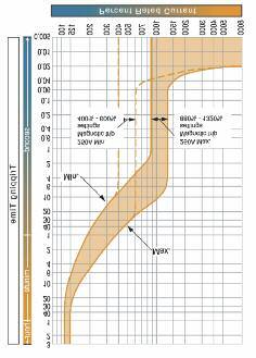
30 Prospective Shortcircuit Current The Prospective Shortcircuit Current, or PSC, is the theoretical maximum fault current that could exist at any point within a complete circuit distribution system. The magnitude of the fault current at any particular point is calculated on the basis of a bolted (virtually permanent) fault path at that point and therefore assumes a constant voltage, continuous current supply feeding the fault. Using this assumption, the PSC that could possibly exist at the bolted fault path would be limited only by the sum of the circuit impedances of the complete current path, from high voltage feed to the supply transformer through to the bolted connection point. Since this assumption cannot be fulfilled in practice (for example, the voltage will not remain constant) the value of calculated PSC can never be exceeded in a practical scheme. The foregoing commentary is particularly relevant to larger commercial and industrial networks, where many subsystems are present and often, many subcircuits within these. For more compact arrangements, such as domestic installations, where the distribution scheme is contained within one or more consumer units, the situation is much simpler. The Regional Electricity Companies generally agree on a fixed fault level of ka at the local zone supply distribution point to one or more dwellings. Those dwellings that lie some distance from the zone origin point of the distributed supply will have reduced PSC due to the higher impedance of the longer run of service cable. Consumer units should therefore have a minimum conditional shortcircuit rating of ka. When an MCB trips, the combination of forced contact separation and rapid arc extinction produces a limiting effect on the fault current such that it will be adequately handled within the normal ka breaking capacity of MCBs fitted to domestic installations. PSC at the origin point In practice and with consideration of the total distribution network; the breaking capacity of an individual circuit device would normally be less than that calculated for the origin point of the scheme. PSC at the connection point The breaking capacity of individual devices must be greater than (or at least equal to) the PSC at the specific point of their connection within a scheme. Conversely, where the circuit device breaking capacity is greater than the PSC at origin, there is no need for further measurement or calculation in this regard. The PSC at any particular connection point can be estimated, calculated, or determined by measurement of the circuit impedance at that point. Measurement of the circuit impedances at all relevant connection points can be a laborious exercise; the calculation method is generally used since this can be readily carried out using one of a number of available computer software packages. PSC by calculation The magnitude of the shortcircuit current (rms value of the ac component) at the connection point will depend upon: The PSC at the origin point. The total resistance in the circuit between the origin point and the relevant circuit reference point. Whether the shortcircuit condition is considered as phasephase, phaseneutral or phaseearth. The maximum PSC at the origin can be calculated from the following formula: PSC (ka) = Supply transformer rating (kva) x 00 x secondary voltage x % transformer reactance PSC by estimation To estimate the PSC, first calculate the total resistance in the LV circuit by determining the sizes and lengths of cables between the supply source and the point under consideration. Next, use the following table to find the cable resistances and summate these to obtain the total resistance. Finally, use this value to read off the estimated PSC from the following graph. 28

31 Maximum Resistance of Copper Conductors at 20 C (milli ohms) Nominal Cable length (m) cross sectional area (mm 2 ) Fault Current (ka) Total Circuit Resistance (mω) 29
32 PSC in a typical installation Note that the values on the graph assume a symmetrical fault across the three phases. In a single circuit, for lineneutral faults, the cable resistance value given in the table should be doubled. The following values of PSC would be obtained at the various circuit points marked in the above diagram: Point A Point B Point C Point D PSC = approximately 27kA Two cables per phase, therefore halve the value. Resistance from A to B With reference to the graph PSC can be assumed to be 25kA Resistance from A to B Resistance from B to C Total circuit resistance A to C With reference to the graph PSC can be assumed to be 2kA Resistance from A to B Resistance from B to C Resistance from C to D (Double the value for the 2core cable) Total circuit resistance A to D With reference to the graph PSC can be assumed to be ka = 0. Milli ohms = 0. Milli ohms = 0.7 Milli ohms =.0 Milli ohms = 0. Milli ohms = 0.7 Milli ohms =.0 Milli ohms = 57.0 Milli ohms 0
33 Earth Fault Protection One of the most common means of protecting persons against the effects of high voltages and currents is by insulating the wiring and components. Most earth faults occur when some part of the insulation has broken down, creating the possibility of causing electric shock through indirect contact with the faulty circuit. The breakdown of insulation can often cause all or part of an enclosure or frame to become live by raising conductive parts to a hazardous voltage level. Touching any of the exposed parts of the enclosure or frame would then be highly dangerous and would most likely cause an electric shock. Whilst protective devices may open quickly to minimise the possibility of high currents flowing for any significant length of time, additional measures are necessary to limit the potential earth fault current at source. In some cases fault current limiting resistors or inductors may be installed at the transformer star point however, in all cases, it is important to ensure that the impedance of circuit conductors is kept to a minimum so that the voltage developed under fault conditions will be restricted. The earth fault loop impedance is denoted Zs and is an important circuit design parameter. Circuit designs must always ensure that the magnitude of the fault current will be sufficient to trip the overcurrent protective devices within acceptable times as stated in the IEE Wiring Regulations. Circuit breakers are designed to trip and therefore disconnect faulted circuits very quickly. The design value of tripping time is generally expressed in the form of a graph that maps current against time and any practical scheme can be checked against this value to ascertain conformance with the requirements. The fault current can be established very simply using Ohm s law, as follows: Fault current = Minimum phase to earth voltage Zs Once this value is known, the corresponding maximum tripping time can be read from the relevant device s time/current characteristic graph and the result compared with that given within the Wiring Regulations. In general, the higher the nominal voltage of an installation, the shorter will be the required disconnection time. For fixed equipment installations, the maximum disconnection time is stated as 5 seconds, whereas it is 0. seconds for portable equipment. The Regulations define portable as including fixed outlet sockets that may be used to supply apparatus that is movable or portable when in use. The following table illustrates the maximum Zs allowable for MCBs to achieve the specified disconnection times. Current rating (A) B type C type D type 0.s 5s 0.s 5s 0.s 5s The table on the left is based on maximum allowable Earth loop impedance values in accordance with BS77:2008 incorporating Amendment, 205. Since the complete loop impedance is the sum of the individual impedances of the supply transformer winding, circuit phase conductor and protective circuit conductor, the total may be higher than that specified for intime disconnection for the protection device proposed. In these cases, several solutions may be possible to overcome or at least assist in achieving compliance. The supply cable may be replaced by one with greater cross sectional area The shortcircuit tripping threshold of the device may be set to a lower value (if it is adjustable) A Residual Current Device could be used to replace the circuit breaker in question The following tables indicate the maximum Zs for Dorman Smith s range of MCCBs. Using these tables obviates the need to determine the suitability of a device by reference to its time/current characteristic graph.
34 Zs Values for YB and YA2 MCCBs Maximum Allowable Earth Loop Impedance Values, in accordance with BS77:2008 incorporating Amendments, 205 MCCB Reference Instantaneous (Ii) Zs 20Vac Protection Setting In 0. sec 5 sec YB P Fixed Thermal 0.0. / Fixed Magnetics YBN, 25 ka YB P & P Adjustable Thermal / Fixed Magnetics YBN, 25kA YBS, 0kA YA2 P Fixed Thermal / Fixed Magnetics YA2N, 25kA YA2 P & P Adjustable Thermal / Adjustable Magnetics YA2S, ka YA2J, 5kA MIN MAX MIN MAX MIN MAX MIN MAX MIN MAX MIN MAX
35 Zs Values for YA, YB and YA5 MCCBs Maximum Allowable Earth Loop Impedance Values, in accordance with BS77:2008 incorporating Amendment, 205 MCCB Reference Instantaneous (Ii) Zs 20Vac Protection Setting In 0. sec 5 sec YA P Fixed Thermal..22 / Fixed Magnetics YAN, 25kA YA P & P Adjustable Thermal / Adjustable Magnetics YAS, ka YAJ, 5kA MIN MAX MIN MAX MIN MAX MIN MAX MIN MAX MIN MAX MIN MAX MIN MAX MIN MAX YB P & P Adjustable FIXED Thermal / Adjustable FIXED Magnetics MIN YBN, 25kA MAX YBS, 0kA MIN MAX MIN MAX MIN MAX MIN MAX YA5 P & P Adjustable Thermal/Adjustable Magnetic YA5N, 25kA YA5H, 50kA YA5 P & P Electronic MIN MAX MIN MAX Short time (lsd) Protection Setting YA5JE, 5kA MIN YA5KE, 70kA MAX MIN MAX
36 Zs values for YA, YA7 and YA8 MCCBs Maximum Allowable Earth Loop Impedance Values, in accordance with BS77:2008 incorporating Amendment, 205 Loadline MCCBs Instantaneous (Ii) Protection Setting Zs 20Vac In 0. sec 5 sec YA P & P Adjustable MIN (YAH Only) Thermal/Adjustable MAX (YAH Only) Magnetics MIN YAH, 50kA MAX YAK, 70kA MIN MAX YA P and P Electronic YAHE, 50kA YAKE, 70kA Short time (lsd) Protection Setting MIN MAX YA7 P & P Electronic YA7HE, 50kA YA7KE, 70kA YA8 P & P Electronic YA8HE, 50kA YA8KE, 85kA MIN MAX Short time (lsd) Protection Setting MIN MAX Short time (lsd) Protection Setting MIN MAX
37 Loadline YA/YB Thermal and Magnetic Adjustment Settings MCCB Frame/Type Loadline YB Frame Thermal/Magnetic MCCBS Rated Current In (A) Magnetic Trip Current Thermal Trip (li) Adjustment Current (lr) Adjustment YBN ( pole), 20, 25, 2, 0, 50 00A FIXED FIXED, A FIXED 00, A FIXED YBN & YBS 25, 2, 0 00A FIXED 0. x In, 0.8 x In,.0 x In, A FIXED 00, A FIXED 0 00A FIXED YBN & YBS 50 50A FIXED 0. x In, 0.8 x In,.0 x In 89A FIXED 00, 25, 0, x In x In x In x In MCCB Frame/Type Loadline YA Frame Thermal/Magnetic MCCBS Rated Current In (A) Magnetic Trip Current Thermal Trip (li) Adjustment Current (lr) Adjustment YA2N ( pole) 208A FIXED FIXED 20 20A FIXED 25 25A FIXED 2 20A FIXED 0 520A FIXED 50 50A FIXED 820A FIXED 80 00A FIXED 00 00A FIXED A FIXED YA2S & YA2J 20, 2, 50,, 00 x In 2 x In 0. x In, 0.8 x In,.0 x In 25 x In 0 x In YAN ( pole) 0A FIXED FIXED A FIXED A FIXED 2 20A FIXED 0 00A FIXED A FIXED 0A FIXED A FIXED A FIXED A FIXED 0 00A FIXED YAS 20, 2 x In 2 x In 0. x In, 0.8 x In,.0 x In YAJ 50,, 00, 25 x In 2 x In 0. x In, 0.8 x In,.0 x In 0, 200 x In x In 250 x In 0 x In YA5N, YA5H & YA5J 250,00 x In 2 x In 0. x In, 0.8 x In,.0 x In YAH x In 5.75 x In FIXED YAH & YAK 0, x In 0 x In 0. x In, 0.8 x In,.0 x In 5
38 Forms of Separation The principle of separation applied to multicubicle switchboards and panel boards is the achievement of a high degree of safety for equipment and people during normal operation and to promote safe working during commissioning and service. The resulting concept is one of functional separation and segregation of live parts of the system into subunits by the use of barriers or partitions. In general, separation should provide enhanced safety by: Protecting against contact with the live parts of adjacent functional units Preventing the passage of solid foreign bodies from one section of an assembly to an adjacent one Various elements of an assembly must be considered for separation from neighbouring live sections, such as busbars, terminals and functional units. The specific form of their separation can be achieved in several ways according to the particular application and the requirements for access for maintenance. The minimum degree of protection to be achieved at each barrier or partition is to IP2X as specified in the Ingress Protection standard EN Typically, this may include: PVC sleeving, wrapping or plastic coating of conductors Insulated terminal shrouds or PVC boots Rigid insulated barriers or partitions Compartments formed from earthed metal A device s integral housing There are several forms of separation, indicated by numbered category and subcategory; however the requirements for the degree of separation need to be carefully considered since the cost increases significantly with increased degree. The principal categories are: Form No separation Typical applications are where the assembly is to be placed in a secure location and where failure will cause little or no additional disruption to other areas being supplied by that particular assembly. Form 2 Separation of busbars from functional units Applications may be similar to those of Form but where it is important that a fault need not affect all functional units being supplied by the same busbar system. Form Separation of busbars from functional units and the functional units from one another, but not their terminations This form should be applied where it is important to provide protection from internal live parts and where failure of functional units being supplied from the same busbar would cause unacceptable disruption. Form Separation of busbars from functional units and the functional units from one another, including their terminals This form should be applied where it is important to provide protection from internal live parts and where failure of functional units being supplied from the same busbar would cause unacceptable disruption. Because all the terminations are separated, it is possible to isolate and work on a single functional unit. Dorman Smith LFtype panel board systems are supplied in Form 2 as standard, with Form versions achieved with simple conversion kits. However, other separation forms can be provided in special cases. With the exception of Form, the other separation forms have subcategories that permit permutations of the general form to be configured according to the requirements for specific applications and to allow the accommodation of different types of protection method. The exact form of separation provided on an assembly is a matter for agreement between the manufacturer and the end user.


39 Subcategories of Separation Forms Main criteria Sub criteria Form Type Construction No separation Separation of busbars from the functional units Terminals for external conductors not separated from busbars 2a Terminals for external conductors separated from busbars 2b 2 Separation of busbars from the functional units and separation of all functional units from one another. Separation of the terminals for external conductors from functional units but not from each other Separation of busbars from the functional units and separation of all functional units from one another including terminals for external conductors which are an integral part of the functional unit Terminals for external conductors not separated from busbars Terminals for external conductors separated from busbars Terminals for external conductors in the same compartment as the associated functional unit Terminals for external conductors not in the same compartment as the associated functional unit but in individual, separate, enclosed protected spaces or compartments a b 2 a 2 b 5 7 Busbar separation by insulated coverings Busbar separation by rigid barriers Busbar separation by insulated coverings Busbar separation by rigid barriers Busbar separation by insulated coverings. Cables may be glanded elsewhere Busbar separation by rigid barriers. Cables may be glanded elsewhere All separation by rigid barriers The termination for each functional unit has its own integral glanding facility Busbar separation by insulated coverings. Cables may be glanded elsewhere Busbar separation by rigid barriers. Terminals may be separated by insulated coverings and glanded in common cabling chambers All separation by rigid barriers Cables are glanded in common cabling chambers All separation by rigid barriers The termination for each functional unit has its own integral glanding facility Form a Group Mounted Form a Type 2 Compartmentalised Form b Type Compartmentalised 7
40 Ingress Protection The EN 0529 standard describes a system for classifying degrees of protection against the ingress of foreign bodies and harmful liquids. It is intended that this standard is applied to enclosures of low voltage (LV) electrical equipment. The classification scheme comprises a designation prefixed by the upper case letters IP, followed by two numerals. The first numeral designates the degree of protection with regard to solid objects; the second numeral indicates the degree of protection against the ingress of liquid. Compliance to the standard is intended to: Protect persons against access to hazardous parts inside enclosures and protect the equipment inside the enclosure against the ingress of solid foreign objects. Protect the equipment inside the enclosure against harmful ingress of liquids. First Protection against ingress of solid objects or dust Equivalent Number 0 No protection 50mm diameter solid foreign object Back of hand 2 2.5mm diameter solid foreign object Finger 2.5mm diameter solid foreign object Tool mm diameter solid foreign object Wire 5 Limited ingress of dust (no harmful deposit) Wire Total protection against dust ingress Wire X Not tested Second Protection against the ingress of water Equivalent Number 0 No protection Against vertically falling water drops Vertical drips 2 As in, but with enclosure tilted 5 degrees from vertical Slanted dripping to 5 degrees from vertical Against spray to 0 degrees from vertical limited Limited spray ingress permitted Against splashing from any direction limited ingress permitted Splashing from any direction 5 Against low pressure jets from any direction limited ingress permitted Hosing jets from any direction Against strong jets from any direction Power hosing from any direction 7 Against immersion up to one metre Temporary immersion 8 Against prolonged immersion under pressure Continuous immersion X Not tested For assemblies for indoor use where there is no requirement for the protection against ingress of water, the following IP codes are preferred: IP00, IP2X, IPX, IPX, IP5X, IPX. Additional Letter of IP code A B C D Protection of persons against access to hazardous (live or moving) parts inside the enclosure Back of hand (50mm diameter) Standard jointed test finger (2mm diameter, 80mm length) Tool 2.5mm diameter, 00mm length Wire.0mm diameter, 00mm length 8
41 Insulation Distances for Loadline YA Frame MCCBs The insulation distances between an MCCB and adjacent earthed metal parts and insulators shown in the diagram below must be maintained to prevent arcing faults occurring due to conductive ionised gases. In cases where requirements differ from those illustrated here, the greater distance must be maintained. Where two different YA frame devices are installed one above the other, the insulation distance between the two should be as for the lower size of MCCB. Exposed conductors must be insulated up to the barrier terminals. Interphase barriers or terminal covers are recommended. However, if terminal covers are used, the exposed conductor must be insulated until it overlaps the terminal cover.. Insulation plate 2. Top plate (earthed metal). Interphase barriers. Front connected MCCB 5. Front connected MCCB with terminal bar. Rear connected type or plugin type 7. Side panel (earthed metal) A. Distance from lower breaker to exposed live part of upper breaker terminal (front connected type) or from lower breaker to end face of upper breaker (rear connected or plugin type) B. Distance from end face of breaker to top plate B2. Distance from end face of breaker to insulation plate C. Gap between breakers D. Distance from side of breaker to side panel E. Dimensions of insulation over exposed conductors Please see the chart on the next page for the required insulation distances. 9
42 Insulation distance for Loadline YA and YB Frame MCCBs MCCB Distances Frame size Poles A B B2 C D E YA2N *() YA2N / *() YA2S / *() YA2J / *() YBN *() YBN / *() YBS / *() YAN *() YAN / *() YAS / *() YAJ / *() YBN / *() YBS / *() YA5N / *() YA5N / *() YA5J / *() YA5KE / *() YAS / *() YAH / *() YAHE / *() YAK / *() YAKE / *() YA7HE / *() YA7KE / *() YA8HE / *() YA8KE / *() *Note: () Insulate the exposed conductor until it overlaps the mouldied case at the terminal or terminal cover 0
43 Loadline YA2 Frame MCCB Characteristics 250 +/ ' 00A (max) 50' 00A (min) 25A (max) 25A (min) YA2 pole Time/Current Characteristic YA2 and pole Time/Current Characteristic YA2 pole Energy Letthrough YA2 and pole Energy Letthrough


44 Loadline YB & YB Frame MCCB Characteristics YB pole Time/Current Characteristics YBN, YBS and pole Time/Current Characteristics YBN & YBS and pole Time/Current Characteristics up to 200A YBN & YBS and pole Time/Current Characteristics for 250A 2
45 Loadline YA Frame MCCB Characteristics 2500+/ A (max) 250A (min) YA pole Time/Current Characteristic YA and pole Time/Current Characteristic YA pole Energy Letthrough YA and pole Energy Letthrough
 YA5 and pole Energy")
46 Loadline YA5 Frame MCCB Characteristics YA5 and pole Time/Current Curve (Thermal / Magnetic) YA5 and pole Energy Letthrough


47 Loadline YA5 Frame MCCB Characteristics YA5 and pole Time/Current Curve (Electronic) 5

 YA Magnetic")


48 Loadline YA Frame MCCB Characteristics YA Time/Current Curve (Thermal / Magnetic 00A0A) YA Time/Current Curve (Thermal / Magnetic 800A) YA In = 0A, 800A Ground fault: lg = 0.2 x In and tg = 0.2 seconds YA Time/Current Curve (Electronic 0800A)

49 Loadline YA7 Frame MCCB Characteristics YA7 Time/Current Characteristic YA7 In = 250A Ground fault: lg = 0.2 x In and tg = 0.2 seconds 7


50 Loadline YA8 Frame MCCB Characteristics YA8 Time/Current Characteristic YA8 In = 00A Ground fault: lg = 0.2 x In and tg = 0.2 seconds 8
technical information
 technical information protection devices 192 circuit protection principle 194 circuit breakers characteristics 200 moulded case circuit breakers (MCCB) 205 prospective fault current 208 selectivity and
A9 R Range Family Code Internal code Poles Code Rating (A) Code Acti 9 (A9) iid R
 Code Acti 9 (A9) iid R") Earth leakage protection Principle of catalogue numers A9 R 15 2 63 Range Family Code Internal code Poles Code Rating (A) Code Acti 9 (A9) iid R 0 0 0 00 Vigi ic60 V 1P 1 0.5 70 ic60 F 2P 2 0.75 71 ik60
Earth leakage protection Principle of catalogue numers A9 R 15 2 63 Range Family Code Internal code Poles Code Rating (A) Code Acti 9 (A9) iid R 0 0 0 00 Vigi ic60 V 1P 1 0.5 70 ic60 F 2P 2 0.75 71 ik60
page 2 of 86 Report reference No:
 articulars: test item vs. test requirements 3. Classification 3.1. Utilization category: (A or B)... : A 3.2. Interruption medium: (air, vacuum, gas Break)... : Air 3.3. Design: (open construction, moulded
3 - Protection components Circuit-breakers
 Contents - Protection components Circuit-breakers for the motor protection Selection guide..............................................page /2 Thermal-magnetic motor circuit-breakers Selection guide..............................................page
Page 13-2 Page Page 13-7
 Page -2 Page -6 MINIATURE CIRCUIT BREAKERS UP TO 63A 1P, 1P+N, 2P, 3P and 4P versions IEC rated current In: 1-63A IEC short-circuit capacity Icn: 10kA (6kA for 1P+N) Trip characteristic curve: Type B,
(1,5 modules per pole)
") 87045 LIMOGES Cedex Telephone: +33 5 55 06 87 87 FAX: +33 5 55 06 88 88 DX 3 MCB 25kA 80A to 125A CONTENTS PAGES 1. Description - Use... 1 2. Range... 1 3. Overall dimensions... 1 4. Preparation - Connection...
87045 LIMOGES Cedex Telephone: +33 5 55 06 87 87 FAX: +33 5 55 06 88 88 DX 3 MCB 25kA 80A to 125A CONTENTS PAGES 1. Description - Use... 1 2. Range... 1 3. Overall dimensions... 1 4. Preparation - Connection...
L O V A G. T E S T I N S T R U C T I O N I E C / E N E d C O N D I T I O N S F O R T E S T I N G
 LTI IEC/EN 60947-4-1 Ed.3.1 L O V A G T E S T I N S T R U C T I O N I E C / E N 6 0 9 4 7-4 - 1 E d. 3. 1 C O N D I T I O N S F O R T E S T I N G C O N T A C T O R S A N D M O T O R - S T A R T E R S This
Electrical Protection System Design and Operation
 ELEC9713 Industrial and Commercial Power Systems Electrical Protection System Design and Operation 1. Function of Electrical Protection Systems The three primary aims of overcurrent electrical protection
Btdin RCD Add-on modules 63A for MCBs 1,5 modules per pole
 Index Pages 1. Descripton... 2 2. Product range... 2 3. Overall dimensions... 2 4. Fixing Connection... 3 5. Generl characteristics... 4 6. Compliance - Approvals... 6 7. Curves... 7 8. Auxiliares and
Residual current circuit breakers (RCCBs)
") Residual current circuit breakers (RCCBs) Description Automatically trips in event of earth leakage fault Provides protection against direct & indirect contact with live parts Technical data IS 12640-1,
Residual current circuit breakers (RCCBs) Description Automatically trips in event of earth leakage fault Provides protection against direct & indirect contact with live parts Technical data IS 12640-1,
Technical features table for miniature circuit-breakers SH 200 Series
 Technical features table for miniature circuit-breakers SH 00 Series Standards Poles Tripping characteristics I n A frequency f Hz insulation voltage U i acc. to IEC/EN 60664-1 V Overvoltage category Pollution
CB Testing Laboratory...:EZÚ Address...:Pod Lisem Praha71-Trója Testing location/ procedure...: CBTL RMT SMT WMT TMP IEC60947_2C
 age 1 of 109 Report No.600332-04/01 TEST REORT Low-voltage switchgear and controlgear art 2: Circuit - breakers Report Reference No....: 600332-04/01 Tested by (name+signature)...:... Witnessed by (name+signature)...:...
Modeion OTHER ACCESSORIES OF MOULDED CASE CIRCUIT BREAKERS
 OTHER ACCESSORIES OF MOULDED CASE CIRCUIT BREAKERS P Other accessories DELAY UNIT Type Product code Description Weight [kg] Package [pc] BZ-BX-X230-A 36696 enables to delay the undervoltage release tripping
Miniature circuit-breakers S 280 UC series. System pro M. Technical data
 Technical data 11 Robbie Rd. / Avon, MA 02322 T:(508)513-1000 F:(508)513-1100 70 Ernest St. / Providence, RI 02905 T:(401)781-7100 www.controllerservice.com System pro M Prior to connection of aluminum
from 0.5 to 125 A Electrical characteristics Sensitivity type (ma) a AC Electrical auxiliaries Auxiliary and alarm switches (OF-SD)
 a AC Electrical auxiliaries Auxiliary and alarm switches (OF-SD)") Acti 9 Acti 9 circuit reakers from 0.5 to 125 A 056903N-32_SE.eps 056806N-28_SE.eps PB104440_28.eps PB107141_28.eps Acti 9 circuit reaker C120N Numer of poles 1 2-3-4 Electrical characteristics Rated current
Acti 9 Acti 9 circuit reakers from 0.5 to 125 A 056903N-32_SE.eps 056806N-28_SE.eps PB104440_28.eps PB107141_28.eps Acti 9 circuit reaker C120N Numer of poles 1 2-3-4 Electrical characteristics Rated current
Add-on modules DX 3 63A for MCBs DX 3 1,5 modules per pole
 87045 LIMOGES Cedex Telephone number: +33 (0)5 55 06 87 87 Fax: +33 (0)5 55 06 88 88 Add-on modules DX 3 63A for MCBs CONTENTS PAGE 1. Description, use... 1 2. Range... 1 3. Overall dimensions... 1 4.
Numbering System for Protective Devices, Control and Indication Devices for Power Systems
 Appendix C Numbering System for Protective Devices, Control and Indication Devices for Power Systems C.1 APPLICATION OF PROTECTIVE RELAYS, CONTROL AND ALARM DEVICES FOR POWER SYSTEM CIRCUITS The requirements
itl impulse relays IEC/EN itls: IEC/EN itls b Allows remote indication of its operating state (open/closed)
") DB123399 DB116619 Country approval pictograms itl, itli, itls, itlc, itlm IEC/EN 60669-2-2 itls: IEC/EN 60947-5-1 Impulse relays B106126-34 B106128-34 itl b The impulse relays are used to control, by means
DB123399 DB116619 Country approval pictograms itl, itli, itls, itlc, itlm IEC/EN 60669-2-2 itls: IEC/EN 60947-5-1 Impulse relays B106126-34 B106128-34 itl b The impulse relays are used to control, by means
Modular equipment. Presentation, standards. Standard contactors TeSys GC
 Presentation, standards Standard contactors TeSys GC Presentation TeSys GC contactors are designed for use in modular panels and enclosures. These contactors feature: b Easy installation v quick clip-on
TeSys circuit-breakers Thermal-magnetic motor circuit-breakers types GV2, GV3 and GV7
 Presentation Thermal-magnetic motor circuit-breakers types GV, GV and GV7 GV-ME, GV-P, GV-ME and GV7-R motor circuit-breakers are -pole thermal-magnetic circuit-breakers specifically designed for the control
Characteristics 5 TeSys k contactors and reversing contactors
 90 Characteristics contactors k contactors and reversing contactors Environment characteristics Conforming to standards IEC 60947, NF C 63-110, VDE 0660, BS 424 Product certifications LCp and LPp K06 to
Low voltage circuit breakers
 Comprehensive Catalogue 2006 Super Solution Low voltage circuit breakers A-4. Technical information TD & TS MCCB Index Temperature derating Power dissipation / Resistance Application Primary use of transformer
Catalog 200 Contactors up to 115 A Motor Starters up to 55 kw 03/2009
 Catalog 00 Contactors up to 5 A Motor Starters up to 55 kw 03/009 Kraus & Naimer The development of the Blue Line rotary switch, contactor and motor starter product ranges is based on more than hundred
Type CP-S, CP-C & CP-A Switch mode
 Switch mode power CP-S, CP-C & CP-A Switch mode Characteristics CP-S and CP-C range Output current 5 A, 10 A and 20 A Integrated power reserve of up to 50 % 5 A and 10 A devices with pluggable connecting
INTERPLANT STANDARD - STEEL INDUSTRY
 INTERPLANT STANDARD - STEEL INDUSTRY SPECIFICATION FOR MOULDED - CASE CIRCUIT-BREAKER FOR VOLTAGES NOT EXCEEDING 1000 V ac OR 1500 V dc (FIRST REVISION) IPSS:1-04-004-11 IPSS BASED ON IS/IEC 60947(Part
Maintenance/Connection/Installation Service life C/O cyclesx1000
 EasyPact MVS 2016 CPB100000 CPB100014 Circuit breaker. Switch disconnector. Common characteristics Number of poles Rated insulation voltage (V) Impulse withstand voltage (kv) Rated operational voltage
LC1D32BD TeSys D contactor - 3P(3 NO) - AC-3 - <= 440 V 32 A - 24 V DC coil
 - AC-3 - <= 440 V 32 A - 24 V DC coil") Characteristics TeSys D contactor - 3P(3 NO) - AC-3 -
Characteristics TeSys D contactor - 3P(3 NO) - AC-3 -
Capacitor Switching Contactors
 Capacitor Switching D385E51 Technical catalogues and news under: www.benedict.at Motor-Starter Mini- Overload Relays Capacitor Switching Motor-Starters Modular Circuit Breakers M4-32T... up to 32A M4-32R..
Modular Devices and Enclosures
 Modular Devices and Enclosures Features Modular contactors for control of motor, heating and lighting applications Digital and Analogue Time Switches for remote command and control of circuits Selectable
LC2D09BD. Main. Device short name. Utilisation category. Poles description Pole contact composition
 Product datasheet Characteristics Main Range Product name Product or component type Device short name Contactor application Utilisation category Device presentation Poles description Pole contact composition
TEST REPORT IEC Low-voltage switchgear and controlgear - Part 2: Circuit-breakers
 Test Report issued under the responsibility of: TEST REORT Low-voltage switchgear and controlgear - art 2: Circuit-breakers Report Reference No.... : 3305316.50 Date of issue... : 2013-09-17 Total number
T e c h n i c a l C a t a l o g u e MCCB. Moulded Case Circuit Breaker
 T e c h n i c a l C a t a l o g u e MCCB Moulded Case Circuit Breaker contents general overview... 2 feature - company profile and certifications... 6 MCCB - NF series circuit breaker, double repulsion
(With the possibility of a tripping coil for remote control) (Generally optional with an electronic tripping device)
 (Generally optional with an electronic tripping device)") Page 1 of 22 Personal tools Log in / create account Circuit-breaker From Electrical Installation Guide The circuit-breaker/disconnector fulfills all of the basic switchgear functions, while, by means of
Page 1 of 22 Personal tools Log in / create account Circuit-breaker From Electrical Installation Guide The circuit-breaker/disconnector fulfills all of the basic switchgear functions, while, by means of
LC1D12BL TeSys D contactor - 3P(3 NO) - AC-3 - <= 440 V 12 A - 24 V DC coil
 - AC-3 - <= 440 V 12 A - 24 V DC coil") Characteristics TeSys D contactor - 3P(3 NO) - AC-3 -
Characteristics TeSys D contactor - 3P(3 NO) - AC-3 -
Type: EASY719 DA RC Article No.: Ordering information Relay outputs Quantity 6 Power supply V DC 12 V DC. Description
 Type: EASY719 DA RC Article.: 274117 Ordering information Relay outputs Quantity 6 Power supply V DC 12 V DC Description 12 digital inputs (4 inputs available as analog inputs) 6 relay outputs LCD display
ECM3 EARTH CONTINUITY RELAY
 TECHNICAL DATASHEET ECM3 EARTH CONTINUITY RELAY Electrical Protection for Hard Rock Mines Application The ECM3 has been designed to provide earth continuity protection for cables containing pilot cores.
Distribution/Substation Transformer
 Distribution/Substation Transformer Type VFI, Vacuum Fault Interrupter Transformer Option Functional Specification Guide Functional specification for 15 kv, 25 kv, or 35 kv vacuum fault interrupter distribution/substation
90 ReStart AUTOMATIC RECLOSING DEVICES
 RESTART WITH AUTOTEST Technical data TYPE ReStart with Autotest 2P ReStart with Autotest PRO 2P ReStart with Autotest PRO 4P Electrical characteristics Standards: EN 50557, EN 61008-1 Distribution system:
LC1D25BL TeSys D contactor - 3P(3 NO) - AC-3 - <= 440 V 25 A - 24 V DC coil
 - AC-3 - <= 440 V 25 A - 24 V DC coil") Product data sheet Characteristics LC1D25BL TeSys D contactor - 3P(3 NO) - AC-3 -
Product data sheet Characteristics LC1D25BL TeSys D contactor - 3P(3 NO) - AC-3 -
Type: EASY719 AC RC Article No.: Ordering information Relay outputs Quantity 6 Power supply V DC 115/230 V AC. Description
 Type: EASY719 AC RC Article No.: 274115 Ordering information Relay outputs Quantity 6 Power supply V DC 115/230 V AC Description 12 digital inputs 6 relay outputs LCD display Operating buttons Screw terminals
Busbars and lines are important elements
 CHAPTER CHAPTER 23 Protection of Busbars and Lines 23.1 Busbar Protection 23.2 Protection of Lines 23.3 Time-Graded Overcurrent Protection 23.4 Differential Pilot-Wire Protection 23.5 Distance Protection
J7M-AM/-BM. Motor--protective circuit--breaker system. J7M -BM System IEC 947, EN IEC 947, EN 60947
 Motor--protective circuit--breaker system J7M -AM System Rated operational current 25 A. Switching capacity up to 10 A, 100 ka/415 V. Switching capacity 16 A, 20 A, 25 A, 16 ka/415 V. Fixed short--circuit
TeSys contactors. TeSys D contactors. IEC/EN , IEC/EN , UL 508, CSA C22.2 n 14. Protection against direct fi nger contact IP 2X
 Characteristics Contactor type LC1 D09 D18 DT20 and DT25 Environment Rated insulation voltage (Ui) Conforming to IEC 097--1, overvoltage category III, degree of pollution: 3 Conforming to UL, CSA V 00
 THE GLOBAL SPECIALIST IN ELECTRICAL AND DIGITAL BUILDING INFRASTRUCTURES P. 20-21 DX³ - MCB AC Application upto 63 A MCBs P. 23 DX³ - 25 ka MCB from 6 A to 125 A Isolator RCCB & RCBOs
Residual Current Operated Circuit-Breakers (RCCBs)
") Product Overview Residual Current Operated Circuit-Breakers (RCCBs) Residual current operated circuit-breakers Number of poles Rated current A Rated residual current ma MW Auxiliary contacts can be mounted
Product Overview Residual Current Operated Circuit-Breakers (RCCBs) Residual current operated circuit-breakers Number of poles Rated current A Rated residual current ma MW Auxiliary contacts can be mounted
CP-T range Product group picture
 Product group picture /1 ABB Catalog Electronic Products and Relays 1/1 2CDC 110 00 C09 Table of contents CP-T range Product group picture /1 Table of contents /2 Benefits and advantages / Ordering details
Content. Monitoring relay pluggable. 1-phase current monitoring relay phase direct-current voltage monitoring relay... 5.
 Content Monitoring relay pluggable 1-phase current monitoring relay... 5.2 1-phase direct-current voltage monitoring relay... 5.6 1-phase voltage monitoring relay... 5.10 3-phase voltage monitoring relay...
ELECTRICAL POWER TRANSMISSION TRAINER
 ELECTRICAL POWER TRANSMISSION TRAINER ELECTRICAL POWER TRANSMISSION TRAINER This training system has been designed to provide the students with a fully comprehensive knowledge in Electrical Power Engineering
Voltage monitoring relay CM-EFS.2 For single-phase AC/DC voltages
 Data sheet Voltage monitoring relay CM-EFS.2 For single-phase AC/DC voltages The CM-EFS.2 is an electronic voltage monitoring relay that provides reliable monitoring of voltages as well as detection of
IGS IGS-M-EL-22(1) Contactors APPROVED. Iranian Gas Standards
 Contactors APPROVED. Iranian Gas Standards") APPROVED IGS Iranian Gas Standards Contactors. Fax:(9821)-8131-5679 --. /012 34-52673892 :;395- 8? /@A7 B;CD /E FGH 34-52673892I2
APPROVED IGS Iranian Gas Standards Contactors. Fax:(9821)-8131-5679 --. /012 34-52673892 :;395- 8? /@A7 B;CD /E FGH 34-52673892I2
Btdin RCD Add-on Modules 32A - 63A for M.C.Bs 1 module per pole
 Index Pages 1. Descripton... 2 2. Product range... 2 3. Overall dimensions... 2 4. Fixing Connection... 3 5. Generl characteristics.... 4-6 6. Compliance - Approvals... 6 7. Curves... 7 1 / 7 1. DESCRIPTION
Power supply CP-T 24/20.0 Primary switch mode power supply
 Data sheet Power supply CP-T 24/20.0 Primary switch mode power supply The CP-T range of three-phase power supply units is the youngest member of ABB s power supply family. In terms of design and functionality,
ELECTRICIAN S THEORY EXAMINATION 17 November 2012 QUESTION AND ANSWER BOOKLET
 Candidate Code No. ET43 For Board Use Only Result Date Int Result Date Int ELECTRICIAN S THEORY EXAMINATION 17 November 2012 QUESTION AND ANSWER BOOKLET INSTRUCTIONS READ CAREFULLY Time Allowed: Three
power Knowledge The Hager Guide to current thinking on the regulations, protection and control of Klik lighting circuits.
 Knowledge is power The Hager Guide to current thinking on the regulations, protection and control of Klik lighting circuits. Written by: Paul Sayer Technical Standards Manager for Hager Contents 2 Conductor
PHOENIX CONTACT - 06/2008. Features. DANGER OF EXPLOSION! Only remove equipment when it is disconnected and not in the potentially explosive area.
 Primary-switched power supply with SFB technology, 1 AC, output current 20 A INTERFACE Data Sheet 103383_en_00 1 Description PHOENIX CONTACT - 06/2008 Features QUINT POWER power supply units highest system
I -limiter The world s fastest switching device
 I S -limiter 2 I S -limiter The world s fastest switching device Reduces substation cost Solves short-circuit problems in new substations and substation extensions Optimum solution for interconnection
Power supply CP-T 24/10.0 Primary switch mode power supply
 Data sheet Power supply CP-T 24/10.0 Primary switch mode power supply The CP-T range of three-phase power supply units is the youngest member of ABB s power supply family. In terms of design and functionality,
LC2D09BL REVERSING CONTACTOR 575VAC 9A IEC
 Product datasheet Characteristics LC2D09BL REVERSING CONTACTOR 575VAC 9A IEC Price* : 107.62 GBP Main Range Product name Product or component type Device short name Contactor application Utilisation category
ABB 1. Multifunctional three-phase monitoring relays. CM-MPS.11, CM-MPS-21, CM-MPS.31 and CM-MPS.41 Data sheet. Features. Approvals. Marks.
 2CDC 251 048 F0t08 CM-MPS.11 2CDC 251 049 F0t08 CM-MPS.21 2CDC 251 050 F0t08 CM-MPS.31 2CDC 251 051 F0t08 CM-MPS.41 R/T: yellow LED - relay status, timing F1: red LED - fault message F2: red LED - fault
A NEW DIRECTIONAL OVER CURRENT RELAYING SCHEME FOR DISTRIBUTION FEEDERS IN THE PRESENCE OF DG
 A NEW DIRECTIONAL OVER CURRENT RELAYING SCHEME FOR DISTRIBUTION FEEDERS IN THE PRESENCE OF DG CHAPTER 3 3.1 INTRODUCTION In plain radial feeders, the non-directional relays are used as they operate when
Btdin RCD Add-on Modules 32A - 63A for M.C.Bs 1 module per pole
 Index Pages 1. Descripton... 2 2. Product range... 2 3. Overall dimensions... 2 4. Fixing Connection... 3 5. Generl characteristics.... 4-6 6. Compliance - Approvals... 6 7. Curves... 7 1 / 7 1. DESCRIPTION
Power supply CP-T 48/20.0 Primary switch mode power supply
 Data sheet Power supply CP-T 48/20.0 Primary switch mode power supply The CP-T range of three-phase power supply units is the youngest member of ABB s power supply family. In terms of design and functionality,
TSX Series. Modicon Manuals. Presented by: Modicon PLC. Schneider Electric Quantum Modicon Gould Gettys
 TSX Series Modicon Manuals Presented by: Modicon PLC Schneider Electric Quantum Modicon Gould Gettys For Product Needs: Email: sales@modiconplc.com Call: 1-800-691-8511 Fax: 919-415-1614 ModiconPLC.com
C&G Level 3 Award in the Periodic Inspection, Testing and Certification of Electrical Installations
 C&G 2395-01 Level 3 Award in the Periodic Inspection, Testing and Certification of Electrical Installations Phase rotation and verification of voltage drop 1 Outcomes of this Session describe how to assess
Power systems Protection course
 Al-Balqa Applied University Power systems Protection course Department of Electrical Energy Engineering 1 Part 5 Relays 2 3 Relay Is a device which receive a signal from the power system thought CT and
ELECTRICIAN S THEORY EXAMINATION 15 November 2014 QUESTION AND ANSWER BOOKLET
 Candidate Code No. ET51 For Board Use Only Result Date Int Result Date Int ELECTRICIAN S THEORY EXAMINATION 15 November 2014 QUESTION AND ANSWER BOOKLET INSTRUCTIONS READ CAREFULLY Time Allowed: Three
Progetto in Inchiesta Pubblica
 N O R M A I T A L I A N A C E I 1 Data Scadenza Inchiesta C. 982 29-02-2008 Data Pubblicazione 2008- Classificazione 17- Titolo Quadri e apparecchi di manovra e di comando per bassa tensione Apparecchi
Components for Marine applications
 Components for Marine applications Imagination GE imagination at work. at work v. 10-2015 GE Industrial Solutions Leading the future of electrification GE Industrial Solutions is leading the future of
Power supply CP-T 48/5.0 Primary switch mode power supply
 Data sheet Power supply CP-T 48/5.0 Primary switch mode power supply The CP-T range of three-phase power supply units is the youngest member of ABB s power supply family. In terms of design and functionality,
Protection of Electrical Networks. Christophe Prévé
 Protection of Electrical Networks Christophe Prévé This Page Intentionally Left Blank Protection of Electrical Networks This Page Intentionally Left Blank Protection of Electrical Networks Christophe Prévé
Power supply CP-T 24/40.0 Primary switch mode power supply
 Data sheet Power supply CP-T 24/40.0 Primary switch mode power supply The CP-T range of three-phase power supply units is the youngest member of ABB s power supply family. In terms of design and functionality,
Instantaneous Overcurrent Relay
 Midos Type MCRI Instantaneous Overcurrent Relay Features High speed operation Not slowed by dc transients Settings readily adjustable on relay front plate Two phase and earth fault relay Figure 1: Type
isw switches Control Local control IEC/EN , isw switch with indicator light. IEC/EN , isw switch without indicator light.
 isw switches DB88 PB0566-40 Position contact indication b Suitable for industrial isolation according to IEC/EN 60947-3 standard. b The presence of the green strip guarantees physical opening of the contacts
QUINT-PS/ 1AC/24DC/20
 Primary-switched power supply with SFB technology, 1 AC, output current 20 A INTERFACE Data sheet 103129_en_04 1 Description PHOENIX CONTACT - 02/2010 Features QUINT POWER power supply units Maximum system
Technical catalogue. Emax Low voltage air circuit-breakers. Hotline:
 Technical catalogue Emax Low voltage air circuit-breakers www.alobitanbd.com Hotline: 01711548558 PAGE : 02 The new Emax have received innumerable international certifications and approval by the major
Current monitoring relays CM-SRS.2 for single-phase AC/DC currents
 Data sheet Current monitoring relays CM-SRS.2 for single-phase AC/DC currents For the monitoring of currents in single-phase AC/DC systems, ABB s CM range comprises a wide selection of powerful and compact
SUGGESTED SPECIFICATION for Series 300 Automatic Transfer Switches
 SUGGESTED SPECIFICATION for Series 300 Automatic Transfer Switches PART 1 GENERAL 1.01 Scope Furnish and install automatic transfer switches (ATS) with number of poles, amperage, voltage, and withstand
LOVAG GENERAL INSTRUCTION G2 MEASUREMENT UNCERTAINTY. This instruction of a general nature and does not relate to specific standards.
 LTI-G2 LOVAG GENERAL INSTRUCTION G2 MEASUREMENT UNCERTAINTY This instruction of a general nature and does not relate to specific standards. It provides additional information ensuring a suitable degree
 Phase control Single function phase control relay - 7.5 mm Control of -phase networks: phase sequence, total phase failure Multi-voltage from x 08 to x 480 V Controls its own supply voltage True RMS measurement
Coordination of LV protection devices
 Technical collection Coordination of LV protection devices Low voltage expert guides n 5 DBTP107EN_Couv.indd 1 12/06/2009 14:32:52 Sans titre-1 1 12/06/2009 14:13:13 Contents Glossary 2 The requirements
PHOENIX CONTACT - 05/2008. DANGER OF EXPLOSION! Remove an item only when it is not connected to power or if it is located in the non-explosive area.
 Primary-switched power supply with SFB technology, 1 AC, output current 20 A INTERFACE Data Sheet 103129_en_01 PHOENIX CONTACT - 05/2008 1 Description QUINT POWER power supply units highest system availability
For non-electrical quantities
 Controlgear 3UG3 monitoring relays 3RS17 interface converters N nsb0346h nsb0348h nsb0775h For electrical quantities For non-electrical quantities 3RS17 interface converter Selection and ordering data
Addendum to Instructions for Installation, Operation and Maintenance of Digitrip 3000 Protective Relays
 Dual-Source Power Supply Addendum to I.B. 17555 Addendum to Instructions for Installation, Operation and Maintenance of Digitrip 3000 Protective Relays Table of Contents Page 1.0 Introduction...1 2.0 General
s s s 3-60 s min min 3-60 min h h 3-60 h V AC, 50/60 Hz
 HPL11002EN DILETTiming relays Rated operational current AC-11 230 V 400 V I th I e I e A A A A A Conventional thermal current Time Range Voltage Article No. See price list Std. pack On-delayed Timing functions
CP-T range Benefits and advantages
 Benefits and advantages Characteristics Rated output voltages V, V DC Output voltage adjustable via front-face rotary potentiometer OUTPUT Adjust Rated output currents 5 A, 10 A, A, A Rated output powers
LC1D12BD TeSys D contactor - 3P(3 NO) - AC-3 - <= 440 V 12 A - 24 V DC coil
 - AC-3 - <= 440 V 12 A - 24 V DC coil") Product data sheet Characteristics LC1D12BD TeSys D contactor - 3P(3 NO) - AC-3 -
Product data sheet Characteristics LC1D12BD TeSys D contactor - 3P(3 NO) - AC-3 -
Miniature circuit breakers. Residential current circuit breakers. Busbar systems. Comfort functions/energy control. Residential enclosures
 .2..4.5.6.7 Technical data Series ME07 Standard range S, S, 0/690V/AC High performance range H, 0/690V/AC High performance range H/S, 000V/AC Disconnecting switch MET DC circuit breaker ME 6T up to 0V/DC
Micro Contactors. Micro Contactor Relays 10. Micro Contactors 11. Micro Contactors With Solder Pins 12. Coil voltages 12. Micro Reversing Contactor 13
 Micro Contactor Relays 10 Micro Contactors 11 Micro Contactors With Solder Pins 12 Coil voltages 12 Micro Reversing Contactor 13 Technical Data 14 Dimensions 18 D946E 9 Micro Contactor Relays 4-pole AC
TABLE OF CONTENT
 Page : 1 of 34 Project Engineering Standard www.klmtechgroup.com KLM Technology #03-12 Block Aronia, Jalan Sri Perkasa 2 Taman Tampoi Utama 81200 Johor Bahru Malaysia TABLE OF CONTENT SCOPE 3 REFERENCES
QUINT-PS/ 3AC/24DC/10
 Primary-switched power supply with SFB technology, 3 AC, output current 10 A INTERFACE Data sheet 103131_en_01 1 Description PHOENIX CONTACT - 09/2009 Features QUINT POWER power supply units Maximum system
10/2 Product overview. 10/3 4AC3 0, 4AC3 1 bell transformers. 10/5 4AC AC3 6 transformers for permanent loads. 10/8 4AC2 4 power supply units
 BETA Switching Transformers, Bells and Socket Outlets /2 Product overview /3 4AC3 0, 4AC3 1 bell transformers /5 4AC3 4... 4AC3 transformers for permanent loads /8 4AC2 4 power supply units / 7LQ2 2 bells
Controls Contactors and Contactor Assemblies Special Applications
 Controls Contactors and Contactor Assemblies Special Applications Price groups 1B, 1H /2 Introduction More information can be found on the Internet: see the opening information, page 13 - Contactors for
E-STOP relays, safety gate monitors
 Safety relay for monitoring E-STOP pushbuttons, safety gates and light barriers. Approvals Unit features Positive-guided relay outputs: 3 safety contacts (N/O), instantaneous 1 auxiliary contact (N/C),
VI 3 - i TABLE OF CONTENTS
 VI 3 - i TABLE OF CONTENTS 3 PROJECT SPECIFIC DATA... 1 3.1 DEFINITIONS... 1 3.1.1 Design Data, High and Medium Voltage... 1 3.1.2 Design Data, Low Voltage Equipment... 2 3.1.3 Phase Relationship... 3
Comparison of recloser and breaker standards
 s Technical Data TD280024EN Supersedes February 1994 (R280-90-5) COOPER POWER SERIES Comparison of recloser and breaker standards Technical Data TD280024EN Comparison of recloser and breaker standards
Section 16621A - AUTOMATIC TRANSFER SWITCH. Part 1 General
 Section 16621A - AUTOMATIC TRANSFER SWITCH Part 1 General 1.01 One 600 Amp, 3 Phase, 480 Volt Automatic Transfer Switch (ATS) shall be provided with gasketed enclosure. The ATS shall consist of an inherently
Protection components
 General Application LT3-Si thermistor protection units continuously monitor the temperature of the machines to be protected (motors, generators, etc.) by means of PTC thermistor probes embedded in the
FIB / FIC. r with Overcurrent Protection (RCBO) Doepke. » effi cient. » reliable. » fl exible. » future-oriented
 Doepke. » effi cient. » reliable. » fl exible. » future-oriented") Doepke The experts in residual current protection technology Residual Current Circuit-Breakers it- r with Overcurrent Protection (RCBO) FIB / FIC» effi cient» reliable» fl exible» future-oriented Doepke
Doepke The experts in residual current protection technology Residual Current Circuit-Breakers it- r with Overcurrent Protection (RCBO) FIB / FIC» effi cient» reliable» fl exible» future-oriented Doepke
Installation and Operational Instructions for ROBA -multiswitch Type 019._00.2
 Guidelines on the Declaration of Conformity A conformity evaluation has been carried out for the product in terms of the EU Low Voltage Directive 2014/35/ EU and the Electromagnetic Compatibility (EMC)
NIRAPOD 1. High performance circuit breaker mcb and combined mcb with remote controls. LV Distribution Products 2-63A
 High performance circuit breaker mcb and combined mcb with remote controls LV Distribution Products 2-63A Mini motorized circuit breaker The mini-series of motorized circuit breakers operates both locally