Low voltage circuit breakers
|
|
|
- Margaret Perry
- 6 years ago
- Views:
Transcription

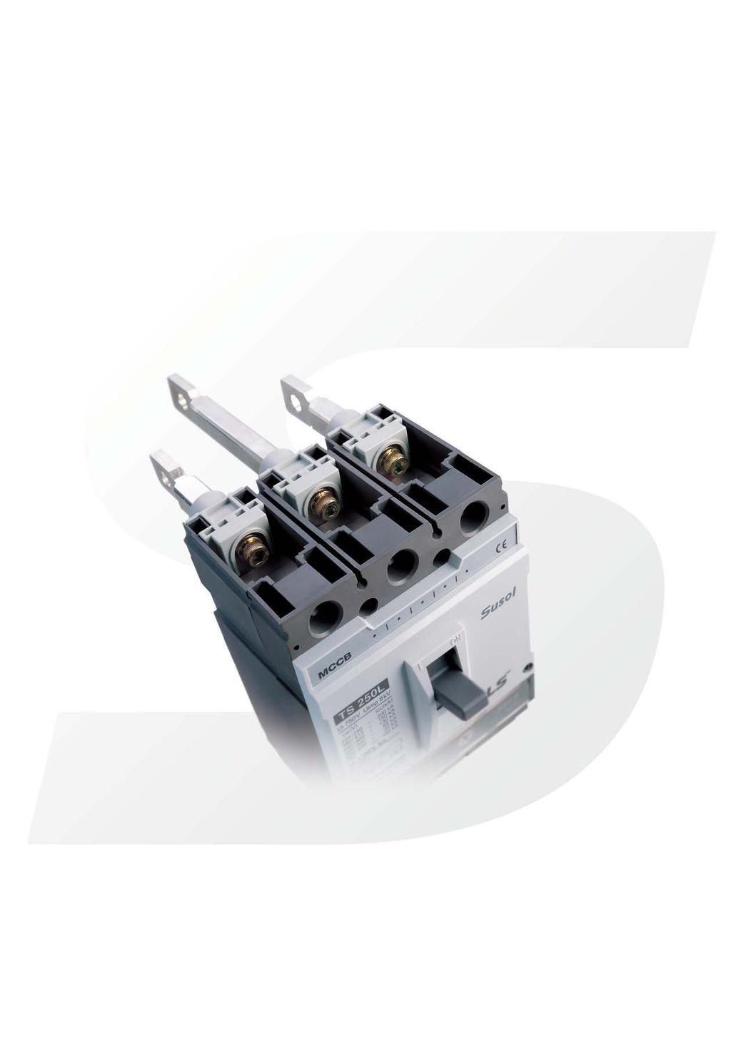
1 Comprehensive Catalogue 2006 Super Solution Low voltage circuit breakers
2
3 A-4. Technical information TD & TS MCCB Index Temperature derating Power dissipation / Resistance Application Primary use of transformer Protection of lighting & heating circuits Protection of resistance welding circuits Use of circuit-breakers for capacitor banks Using circuit-breakers in DC networks Circuit breakers for 400Hz networks Protection of several kinds of loads Protective coordination Discrimination & Cascading Cascading, network 220/240V Cascading, network 380/415V Cascading, network 480/500V Motor protection cascading, network 220/240V Motor protection cascading, network 380/415V Motor protection cascading, network 480/500V Protection discrimination table, Discrimination Motor protection discrimination table Type 2 Coordination according to IEC How to calculate short-circuit current value Various short-circuit With percent impedance With a simple formula Calculation example Combination of transformer and impedance Various short-circuit Calculation example Calculation graph A-4-1 A-4-3 A-4-4 A-4-6 A-4-7 A-4-8 A-4-11 A-4-12 A-4-14 A-4-16 A-4-17 A-4-20 A-4-23 A-4-26 A-4-27 A-4-28 A-4-29 A-4-39 A-4-41 A-4-46 A-4-48 A-4-50 A-4-52 A-4-56 A-4-57 A-4-58 A-4-59
4 Temperature derating A derating of the rated operational current of the Susol TD and TS molded case circuit breaker is necessary if the ambient temperature is greater than 40 C. Namely, when the ambient temperature is greater than 40 C, overload-protection characteristics are slightly modified. Electronic trip units are not affected by variations in temperature. But, the maximum permissible current in the circuit breaker depends on the ambient temperature. Susol TD & TS series MCCB with thermal-magnetic trip units AF Fixed MCCB (c/w Thermal-magnetic trip unit) Rating (A) 10 C 20 C 30 C 40 C 50 C 60 C 70 C TD TD TS TS TS TS TS TS A-4-1
5 Temperature derating Susol TD & TS series MCCB with thermal-magnetic trip units AF Plug-in MCCB (c/w Thermal-magnetic trip unit) Rating (A) 10 C 20 C 30 C 40 C 50 C 60 C 70 C TS TS TS TS TS TS TS TS A-4-2
6 Power dissipation / Resistance Susol TD & TS series MCCB with thermal-magnetic trip units AF TD (3P & 4P) Rating (A) R (m ) Fixed Watt single pole MCCB Watt three poles R (m ) Plug-in Watt single pole MCCB Watt three poles Fixed MCCB Plug-in MCCB AF TD160 (3P & 4P) Rating (A) R (m ) Watt single pole Watt three poles R (m ) Watt single pole Watt three poles Fixed MCCB Plug-in MCCB AF TS,TS160,TS250 (3P & 4P) Rating (A) R (m ) Watt single pole Watt three poles R (m ) Watt single pole Watt three poles Fixed MCCB Plug-in MCCB AF TS400,TS630 (3P & 4P) TS800 (3P & 4P) Rating (A) R (m ) Watt single pole Watt three poles R (m ) Watt single pole Watt three poles Power dissipated per pole (P/pole): Watts (W). Resistance per pole (R/pole): Milliohms (m ) (measured cold). Total power dissipation is the value measured at In, 50/60 Hz, for a 3 pole or 4 pole circuit breaker (Power= 3I 2 R) A-4-3
7 Application Primary use of transformer Application for transformer protection Transformer excitation surge current may possibly exceed 10 times rated current, with a danger of nuisance tripping of the MCCB. The excitation surge current will vary depending upon the supply phase angle at the time of switching, and also on the level of core residual magnetism. So, it s recommended to select proper circuit breakers according to the continuous current carrying capacity of transformer. It requires to consider separately whether transformer is single phase or three phase. The below table indicates the proper molded case circuit breaker suitable for each transformer. AC220V Capacity of 3 phase transformer (kva) Capacity of single phase transformer (kva) Breaking capacity (ka) (sym) Frame (A) AC460V Capacity of 3 phase transformer (kva) Breaking capacity (ka) (sym) Frame (A) Below 1500 Below 1500 Below 2000 Below 3000 Below TDN 160 TD160N TDH TSN TD160H TS160N TSH TS160H TDL TSL TD160L TS160L 250 TS250N TS250H TS250L 400 TS400N TS400H TS400L 630 TS630N TS630H TS630L 800 TS800N TS800H TS800L Below 2000 Below 3000 Below TDN TDH TDL TSN TSH TSL 160 TD160N TD160H TD160L TS160N TS160H TS160L 250 TS250N TS250H TS250L 400 TS400N TS400H TS400L 630 TS630N TS630H TS630L 800 TS800N TS800H TS800L A-4-4
8 Application Primary use of transformer Application for transformer protection (MCCBs for Transformer-Primary Use) Transformers are used to change in the supply voltage, for both medium and low voltage supplies. The choice of the protection devices should be considered transient insertion phenomena, during which the current may reach values higher than the rated full load current; the phenomenon decays in a few seconds. The peak value of the first half cycle may reach values of 15 to 25 times the effective rated current. For a protective device capable of protecting these units this must be taken into account. Manufacturers data and tests have indicated that a protective device feeding a transformer must be capable of carrying the following current values without tripping. TD ~ TS800 equipped with Thermal magnetic trip units Transformer ratings (kva) MCCB rated 1 phase 230V 3 phase 230V current Trip unit 1 phase 230V 1 phase 240V (A) 3 to 4 5 to 6 9 to to 5 6 to 8 11 to to 6 8 to to to 7 10 to to to 9 13 to to to to to to to to to to to to to to 69 FTU 23 to to to FMU 29 to to to ATU 37 to to to to to 138 to to to to to to to to to to to to to to to to to to to TS ~ TS800 equipped with electronic trip units Transformer ratings (kva) MCCB rated Trip Ir max 3 phase 230V current 1 phase 230V 1 phase 230V unit setting 1 phase 240V (A) 4 to 7 6 to to to to to to to to ETS 23 to to to ETM 37 to to to to 115 to to to to to A-4-5
9 Application Protection of lighting & heating circuits In the lighting & heating circuits, switching-surge magnitudes and times are normally not sufficient to cause serious tripping problems. But, in some cases, such as incandescent lamps, mercury arc lamps, metal halide and sodium vapour, or other large starting-current equipment, the proper selection should be considered. Upon supply of a lighting installation, for a brief period an initial current exceeding the rated current (corresponding to the power of the lamps) circulates on the network. This possible peak has a value of approximately times the rated current, and is present for a few milliseconds; there may also be an inrush current with a value of approximately times the rated current, lasting up to some minutes. The correct dimensioning of the switching and protection devices must take these problems into account. Generally, it is recommended to make the maximum operating current not to exceed 80% of the related current. AC220V The maximum The rated Breaking capacity (ka) operating current of current (A) MCCB (A) sym TDH TDL TDN TDH TDL TDL TSN TSH TSL TD160H TD160N TS160H TD160L TS160N TS160L TS250N TS250H TS250L TS400N TS400H TS400L TS630N TS630H TS630L TS800N TS800H TS800L AC460V The maximum The rated Breaking capacity (ka) operating current of current (A) MCCB (A) sym TDN TDH TDL TSN TSH TSL TD160N TD160H TD160L TS160N TS160H TS160L TS250N TS250H TS250L TS400N TS400H TS400L TS630N TS630H TS630L TS800N TS800H TS800L A-4-6
10 Application Protection of resistance welding circuits Short circuit protection for resistance welding devices can be obtained by applying molded case circuit breaker properly. These breakers permit normally high welding currents, but trip instantaneously if a short circuit develops. It's recommended to select proper circuit breaker according to the characteristics of welding devices as the follow table. Characteristics of welding device Applied circuit breaker (MCCB 2P) Capacity (kva) Maximum input (kva) 220V (Single phase) 400V (Single phase) TDN/H/L A TSN/H/L A TDN/H/L 50A TD160N/H/L A TSN/H/L 50A TS160N/H/L A TDN/H/L A TD160N/H/L 125A TSN/H/L A TS160N/H/L 125A TD160N/H/L A TS250N/H/L 125A TS160N/H/L A TD160N/H/L 125A TS250N/H/L 250A TS160N/H/L 125A TS250N/H/L 125A A-4-7
11 Application Use of circuit-breakers for capacitor banks Capacitor circuit C Application for protection of capacitor circuit In order to reduce system losses (less than 0.5W/kvar in low voltage) and voltage drops in the power distribution system, reactive power compensation or power factor correction is generally undertaken. As a result, the power fed into the system is used as active power and costs will be saved through a reduction in the capacitive and inductive power factors. The compensation can be carried out by the fixed capacitors and automatic capacitor banks. However, the disadvantages of installing capacitors are sensitivity to over-voltages and to the presence of nonlinear loads. L1 L2 L Breaker Contactor Examples of equipment which consume reactive energy are all those receivers which require magnetic fields or arcs in order to operate, such as: - Asynchronous motors: An asynchronous motor is a large consumer of inductive reactive energy. The amount of reactive power consumed is between 20% and 25% of the rated power of the motor (depending on its speed). T1 T2 T3 M Motor O/L C - Power Transformers: Power transformers are normally always connected. This means that reactive energy is always consumed. Also, as a consequence of its inductive nature, the reactive energy increases when the transformer is loaded. L1 L2 L3 - Discharge lamps, Resistance-type soldering machines, Dielectric type heating ovens, Induction heating ovens, Welding equipments, Arc furnaces Breaker Contactor O/L At the instant of closing a switch to energize a capacitor, the current is limited only by the impedance of the network upstream of the capacitor, so that high peak values of current will occur for a brief period, rapidly falling to normal operating values. T1 T2 T3 M Motor L1 L2 L Breaker C Breaker According to the relevant standards IEC /IEC 70, capacitors must function under normal operating conditions with the current having a RMS value up to 1.3 times the rated current of the capacitor. Additionally, a further tolerance of up to 15% of the real value of the power must be taken into consideration. The maximum current with which the selected circuit-breaker can be constantly loaded, and which it must also be able to switch, is calculated as follows: Maximum expected rated current= Rated current of the capacitor bank 1.5 (RMS value) Contactor O/L C T1 T2 T3 M Motor Usual connection diagram A-4-8
12 Application Use of circuit-breakers for capacitor banks 220V, 50/60Hz Circuit Single-phase circuit Three-phase circuit Capacitor rating Capacitor rated MCCB rated Capacitor rated MCCB rated kvar current (A) current (A) current (A) current (A) Notes) 1. The MCCB rated current should be approx. 150% of the capacitor rated current. 2. The MCCB short-circuit capacity should be adequate for the circuit short-circuit capacity. A-4-9
13 Application Use of circuit-breakers for capacitor banks 440V, 50/60Hz Circuit Single-phase circuit Three-phase circuit Capacitor rating Capacitor rated MCCB rated Capacitor rated MCCB rated kvar current (A) current (A) current (A) current (A) Notes) 1. The MCCB rated current should be approx. 150% of the capacitor rated current. 2. The MCCB short-circuit capacity should be adequate for the circuit short-circuit capacity. A-4-10
14 Application Using circuit-breakers in DC networks Susol circuit-breakers for protection of power distribution with thermal overload and magnetic shortcircuit trip units are suitable for usage in DC networks. The circuit-breakers with electronic overcurrent releases are not suitable for DC networks. Circuit-breaker selection criteria The followings are the most important criteria for selection of suitable circuit breaker for DC networks. The rated current determines the rating and size of the circuit-breaker (Equipment) The rated voltage determines the number of poles in series necessary for breaking The maximum short-circuit current at the connection point determines the breaking capacity Setting range of the trip values Thermal overload protection: Same setpoints as in 50/60Hz circuits Instantaneous short-circuit protection: The response threshold increases by maximum 40%. The following wiring diagrams are recommended since the current must flow through all current paths in order to conform to the thermal tripping characteristic curve. -(N) +(P) -(N) +(P) Load Recommended wiring method for DC500V circuit Load Recommended wiring method for DC600V circuit Model Trip unit Applicable to DC circuits Breaking capacity (ka) TDN,TD160N 42 TSN,TS160N, TS250N TS400N, TS630N 50 TS800N TDH, TD160H 65 Thermal TSH, TS160H, TS250H FTU magnetic TS400H, TS630H FMU 85 TS800H ATU TDL, TD160L TSL, TS160L, TS250L TS400L, TS630L TS800L Electronic TS250, TS630, TS800 ETS, ETM Impossible to use to DC circuits A-4-11
15 Application Circuit breakers for 400Hz networks When circuit breakers are used at high frequencies, the breakers in many cases require to be derated as the increased resistance of the copper sections resulting from the skin effect produced by eddy currents at 400Hz. Standard production breakers can be used with alternating currents with frequencies other than 50/60 Hz (the frequencies to which the rated performance of the device refer, with alternating current) as appropriate derating coefficients are applied. Thermal magnetic trip units Thermal trip As can be seen from the data shown in below, the tripping threshold of the thermal element (ln) decreases as the frequency increases because of the reduced conductivity of the materials and the increase of the associated thermal phenomena. Rated current (A) at 400Hz= K1 rated current (A) at 50/60Hz Instantaneous trip The magnetic threshold increases with the increase in frequency. Instantaneous current (A) at 400Hz= K2 Instantaneous current (A) at 50/60Hz Thermal magnetic trip units TD and TS series performance table at 400Hz Rated current Multiplier factors (K1, K2) Applied circuit breaker (A) Trip unit K1 K2 (MCCB) in 400 Hz (Thermal trip units) (Magnetic trip units) TDN, TDH, TDL TSN, TSH, TSL TD160N, TD160H, TD160L TS160N, TS160H, TS160L FTU FMU ATU TS250N, TS250H, TS250L TS400N, TS400H, TS400L TS630N, TS630H, TS630L TS800N, TS800H, TS800L Note) K1 Multiplier factor of rated current (In) K2-Multiplier factor of instantaneous current due to the induced magnetic fields FTU-Fixed Thermal and magnetic trip unit FMU Adjustable thermal and fixed magnetic trip unit ATU Adjustable thermal and magnetic trip unit A-4-12
16 Application Circuit breakers for 400Hz networks Electronic trip units The use of electronics offers the advantage of greater operating stability when the frequency is varied. However, the devices are still subjected to frequency related temperature effects which may sometimes pose restrictions on their use. Column K1 of the table below gives the maximum permissible current to be used for the current setting (knob position). TS series performance table at 400Hz Electronic trip units Rated current Multiplier factors (K1, K2) Applied circuit breaker (A) Trip unit K1 K2 (MCCB) in 400 Hz (Thermal trip units) (Magnetic trip units) to 1 1 TSN, TSH, TSL to 1 1 TS160N, TS160H, TS160L to TS250N, TS250H, TS250L ETS to TS400N, TS400H, TS400L ETM to TS630N, TS630H, TS630L to TS800N, TS800H, TS800L to Note) ATU Adjustable thermal and magnetic trip unit K1 Multiplier factor of rated current (In) K2-Multiplier factor of instantaneous current due to the induced magnetic fields ETS Electronic trip unit (Standard) ETM Electronic trip unit (Multi-function) A-4-13
17 Application Protection of several kinds of loads Application for protection of several kinds of loads It requires to select proper circuit breakers according to the characteristics of loads when they are installed to protect several kinds of loads. It's needed to consider the maximum operating current and the capacity of loads in total so as to select the rated current of breakers. Selection of circuit breaker protecting the several loads simultaneously The kind of loads Permissible current The rated current (IM: motors, IL: others) in cable or wire: IW of circuit breaker: Ib In case of, M IM1 IM IL Ib Iw M IM2 IL1 IW IM + IL Choose the low value among IL2 two formulas: In case of, M IM1 Ib 3 IM + IL. and IM IL, IM 50A Ib Iw M IM2 IL1 Iw 1.25 IM + IL Ib 2.5IW IL2 It s permitted to select the above value In case of, IM IL, IM 50A Ib Iw M IM1 M IM2 IL1 IW 1.1 IM + IL only if IW (above A) isn t subject to the rated current of circuit breaker. IL2 The rated current of breakers as the main circuit of 3 phase inductive loads (AC 220V) Capacity of The maximum Capacity of the highest motor (kw / A) loads In total operating current (below kw) (below A) A-4-14
18 Application Protection of several kinds of loads The rated current of breakers as the main circuit of 3 phase inductive loads (AC 440V) Capacity The maximum Capacity of the highest motor (kw / A) of loads In total operating current (below kw) (below A) Notes) The above mentioned technical data is defined under the usage conditions as follows ; 1. The circuit breaker is tripped within 10seconds in 600% of the current of the fully operating loads. 2. The start-up input current is set within 1700% of the current of the fully operating loads. 3. The capacity of highest motor is also applied when several loads starts up simultaneously. A-4-15
19 Protective coordination Discrimination & Cascading The primary purpose of a circuit protection system is to prevent damage to series connected equipment and to minimize the area and duration of power loss. The first consideration is whether an air circuit breaker or molded case circuit breaker is the most suitable. The next is the type of system to be used. The two major types are: Discrimination and cascading. Comtinuous supply Healthy circuit Main breaker Main breaker Branch breaker Short-circuit point Branch breaker Fault point Discrimination According to IEC , the discrimination can be defined as follows. Total discrimination (total selectivity) Over-current discrimination where, in the presence of two over-current protective devices in series, the protective device on the load side effects the protection without causing the other protective device to operate. Partial discrimination (partial selectivity) Over-current discrimination where, in the presence of two over-current protective devices in series, the protective device on the load side effects the protection up to a given level of over-current, without causing the other protective device to operate. No discrimination In case of a fault, main and branch circuit breakers open. Cascading This is an economical approach to the use of circuit breakers, whereby only the main (upstream) breaker has adequate interrupting capacity for the maximum available fault current. The MCCBs downstream cannot handle this maximum fault current and rely on the opening of the upstream breaker for protection. The advantage of the cascade back-up approach is that it facilitates the use of low cost, low fault level breakers downstream, thereby offering savings in both the cost and size of equipment. As Susol TD & TS circuit breakers have a very considerable current limiting effect, they can be used to provide this cascade back-up protection for downstream circuit breakers. A-4-16
20 Protective coordination Cascading, network 220/240V Complementary technical information Main: Susol TD Branch: Meta-MEC AB, GB and Susol TD, TS Main breaker TDN TDH TDL TD160N TD160H TD160L Branch breaker Rated breaking capacity (karms) ABE103b ABS103b ABH103b ABE203b 35 ABS203b 50 ABH203b 65 AB ABE403b 35 ABS403b 50 ABH403b 85 ABL403b 125 ABE803b 50 ABS803b ABL803b 125 GBN GBH GB GBL GBN GBH GBL TDN TDH TD160N TD160H 200 TSN TSH 120 Susol TS160N TD TS160H 120 & TS250N TS TS250H 120 TS400N TS400H 120 TS630N TS630H 120 TS800N TS800H 120 A-4-17
21 Protective coordination Cascading, network 220/240V Complementary technical information Main: Susol TS Branch: Meta-MEC AB, GB and Susol TD, TS Main breaker TSN TSH TSL TS160N TS160H TS160L TS250N TS250H TS250L Branch breaker Rated breaking capacity (karms) ABE103b ABS103b ABH103b ABE203b ABS203b ABH203b AB ABE403b 35 ABS403b 50 ABH403b 85 ABL403b 125 ABE803b 50 ABS803b ABL803b 125 GBN GBH GB GBL GBN GBH GBL TDN TDH TD160N TD160H TSN TSH Susol TS160N TD TS160H & TS250N TS TS250H TS400N TS400H 120 TS630N TS630H 120 TS800N TS800H 120 A-4-18
22 Protective coordination Cascading, network 220/240V Complementary technical information Main: Susol TS Branch: Meta-MEC AB, GB and Susol TD, TS Main breaker TS400N TS400H TS400L TS630N TS630H TS630L TS800N TS800H TS800L Branch breaker Rated breaking capacity (karms) ABE103b 25 ABS103b 50 ABH103b 65 ABE203b ABS203b ABH203b AB ABE403b ABS403b ABH403b ABL403b ABE803b ABS803b ABL803b GBN GBH GB GBL GBN GBH GBL TDN TDH TD160N TD160H TSN TSH Susol TS160N TD TS160H & TS250N TS TS250H TS400N TS400H TS630N TS630H TS800N TS800H A-4-19
23 Protective coordination Cascading, network 380/415V Complementary technical information Main: Susol TD Branch: Meta-MEC AB, GB and Susol TD, TS Main breaker TDN TDH TDL TD160N TD160H TD160L Branch breaker Rated breaking capacity (karms) ABE103b ABS103b ABH103b ABE203b 18 ABS203b 25 ABH203b 35 AB ABE403b 25 ABS403b 35 ABH403b 50 ABL403b 85 ABE803b 35 ABS803b 50 ABL803b 85 GBN GBH GB GBL GBN GBH GBL TDN TDH TD160N TD160H TSN 50 TSH 85 Susol TS160N 50 TD TS160H 85 & TS250N 50 TS TS250H 85 TS400N 65 TS400H 85 TS630N 65 TS630H 85 TS800N 65 TS800H 85 A-4-20
24 Protective coordination Cascading, network 380/415V Complementary technical information Main: Susol TS Branch: Meta-MEC AB, GB and Susol TD, TS Main breaker TSN TSH TSL TS160N TS160H TS160L TS250N TS250H TS250L Branch breaker Rated breaking capacity (karms) ABE103b ABS103b ABH103b ABE203b ABS203b ABH203b AB ABE403b 25 ABS403b 35 ABH403b 50 ABL403b 85 ABE803b 35 ABS803b 50 ABL803b 85 GBN GBH GB GBL GBN GBH GBL TDN TDH TD160N TD160H TSN TSH Susol TS160N TD TS160H & TS250N TS TS250H TS400N 65 TS400H 85 TS630N 65 TS630H 85 TS800N 65 TS800H 85 A-4-21
25 Protective coordination Cascading, network 380/415V Complementary technical information Main: Susol TS Branch: Meta-MEC AB,GB and Susol TD,TS Main breaker TS400N TS400H TS400L TS630N TS630H TS630L TS800N TS800H TS800L Branch breaker Rated breaking capacity (karms) ABE103b 10 ABS103b 25 ABH103b 35 ABE203b ABS203b ABH203b AB ABE403b ABS403b ABH403b ABL403b ABE803b ABS803b ABL803b GBN GBH GB GBL GBN GBH GBL TDN TDH TD160N TD160H TSN TSH Susol TS160N TD TS160H & TS250N TS TS250H TS400N TS400H TS630N TS630H TS800N TS800H A-4-22
26 Protective coordination Cascading, network 480/500V Complementary technical information Main: Susol TD Branch: Meta-MEC AB, GB and Susol TD,TS Main breaker TDN TDH TDL TD160N TD160H TD160L Branch breaker Rated breaking capacity (karms) ABE103b ABS103b ABH103b ABE203b 10 ABS203b 14 ABH203b 25 AB ABE403b 18 ABS403b 25 ABH403b 35 ABL403b 65 ABE803b 25 ABS803b 45 ABL803b 65 GBN GBH GB GBL GBN GBH GBL TDN TDH TD160N TD160H TSN 42 TSH 65 Susol TS160N 42 TD TS160H 65 & TS250N 42 TS TS250H 65 TS400N 42 TS400H 65 TS630N 42 TS630H 65 TS800N 42 TS800H 85 A-4-23
27 Protective coordination Cascading, network 480/500V Complementary technical information Main: Susol TS Branch: Meta-MEC AB, GB and Susol TD,TS Main breaker TSN TSH TSL TS160N TS160H TS160L TS250N TS250H TS250L Branch breaker Rated breaking capacity (karms) ABE103b ABS103b ABH103b ABE203b ABS203b ABH203b AB ABE403b 18 ABS403b 25 ABH403b 35 ABL403b 65 ABE803b 25 ABS803b 45 ABL803b 65 GBN GBH GB GBL GBN GBH GBL TDN TDH TD160N TD160H TSN TSH Susol TS160N TD TS160H & TS250N TS TS250H TS400N 42 TS400H 65 TS630N 42 TS630H 65 TS800N 42 TS800H 85 A-4-24
28 Protective coordination Cascading, network 480/500V Complementary technical information Main: Susol TS Branch: Meta-MEC AB, GB and Susol TD,TS Main breaker TSN TSH TSL TS160N TS160H TS160L TS250N TS250H TS250L Branch breaker Rated breaking capacity (karms) ABE103b 8 ABS103b 14 ABH103b 25 ABE203b ABS203b ABH203b AB ABE403b ABS403b ABH403b ABL403b ABE803b ABS803b ABL803b GBN GBH GB GBL GBN GBH GBL TDN TDH TD160N TD160H TSN TSH Susol TS160N TD TS160H & TS250N TS TS250H TS400N TS400H TS630N TS630H TS800N TS800H 85 A-4-25
29 Protective coordination Motor protection cascading, network 220/240V Complementary technical information Main: Susol TD,TS Branch: Susol TD,TS Main breaker TDN TDH TDL TD160N TD160H TD160L Branch breaker Rated breaking capacity (karms) TDN TDH TD160N TS TD160H 200 TSN TSH 120 TS160N TS160H 120 Upstream TSN TSH TSL TS160N TS160H TS160L TS250N TS250H TS250L Branch breaker Main breaker capacity (karms) TDN TDH TD160N Susol TD160H TD TSN & TSH TS TS160N TS160H TS250N TS250H Main breaker TS400N TS400H TS400L TS630N TS630H TS630L TS800N TS800H TS800L Branch breaker Rated breaking capacity (karms) TDN TDH TD160N TD160H TSN TSH Susol TS160N TD TS160H & TS250N TS TS250H TS400N TS400H TS630N TS630H TS800N TS800H A-4-26
30 Protective coordination Motor protection cascading, network 380/415V Complementary technical information Main: Susol TD, TS Branch: Susol TD, TS Main breaker TDN TDH TDL TD160N TD160H TD160L Branch breaker Rated breaking capacity (karms) TDN TDH Susol TD160N TD TD160H & TSN 50 TS TSH 85 TS160N 50 TS160H 85 Main breaker TSN TSH TSL TS160N TS160H TS160L TS250N TS250H TS250L Branch breaker Rated breaking capacity (karms) TDN TDH TD160N Susol TD160H TD TSN & TSH TS TS160N TS160H TS250N TS250H Main breaker TS400N TS400H TS400L TS630N TS630H TS630L TS800N TS800H TS800L Branch breaker Rated breaking capacity (karms) TDN TDH TD160N TD160H TSN TSH Susol TS160N TD TS160H & TS250N TS TS250H TS400N TS400H TS630N TS630H TS800N TS800H A-4-27
31 Protective coordination Motor protection cascading, network 480/500V Complementary technical information Main: Susol TD, TS Branch: Susol TD, TS Main breaker TDN TDH TDL TD160N TD160H TD160L Branch breaker Rated breaking capacity (karms) TDN TDH Susol TD160N TD TD160H & TSN 42 TS TSH 65 TS160N 42 TS160H 65 Main breaker TSN TSH TSL TS160N TS160H TS160L TS250N TS250H TS250L Branch breaker Rated breaking capacity (karms) TDN TDH TD160N Susol TD160H TD TSN & TSH TS TS160N TS160H TS250N TS250H Main breaker TS400N TS400H TS400L TS630N TS630H TS630L TS800N TS800H TS800L Branch breaker Rated breaking capacity (karms) TDN TDH TD160N TD160H TSN TSH Susol TS160N TD TS160H & TS250N TS TS250H TS400N TS400H TS630N TS630H TS800N TS800H 85 A-4-28
32 Protective coordination Protection discrimination table, Discrimination Complementary technical information Main: TD~TS800 Branch: AB103~AB203 Branch Main breaker breaker Rating (A) ~ E Trip units- 30 AB103 S Thermal 40 magnetic H E AB203 S Trip units- 150 Thermal 175 magnetic H TDN/H/L TD160N/H/L Trip units-thermal magnetic T T T T T T T T A-4-29
33 TSN/H/L TS160N/H/L TS250N/H/L TS400N/H/L TS630N/H/L TS800N/H/L Trip units-electronic Trip units-electronic T T T T T T T T T T T T T T T T T T T T T T T T T T T T T T T T T T T T T T T T T T T T T T T T T T T T T A-4-30
34 Protective coordination Protection discrimination table, Discrimination Complementary technical information Main: TD160~TS800 Branch: GB103~GB203 Branch Main breaker breaker Rating (A) N GB103 H Trip units- 40 Thermal 50 magnetic L N GB203 H Trip units- 160 Thermal 200 magnetic L TDN/H/L TD160N/H/L Trip units-thermal magnetic A-4-31
35 TSN/H/L TS160N/H/L TS250N/H/L TS400N/H/L TS630N/H/L TS800N/H/L Trip units-electronic Trip units-electronic T T T T T T T T T T T T T T T T T T T T T T T T T T T T T T 12.5 T T T T 12.5 T A-4-32
36 Protective coordination Protection discrimination table, Discrimination Complementary technical information Main: TD/160 (Thermal magnetic) Branch: TD/160 (Thermal magnetic) Main breaker Branch breaker Rating (A) N TD H Trip units- Thermal 16 magnetic L N TD160 H L TDN/H/L TD160N/H/L Trip units-thermal magnetic A-4-33
37 Protective coordination Protection discrimination table, Discrimination Complementary technical information Main: TS/160/250 (Electronic) Branch: TD/160 (Thermal magnetic) Branch breaker Main breaker Rating (A) N TD H Trip units- Thermal 16 magnetic L N TD160 H L TSN/H/L TS160N/H/L TS250N/H/L Trip units-electronic T T T T T T T T T T T T T T T T T T T T T T T T T T T T T T T T T T T T T T T T T T T T T A-4-34
38 Protective coordination Protection discrimination table, Discrimination Complementary technical information Main: TS400/630/800 (Electronic) Branch: TD/160 (Thermal magnetic) Main breaker Branch breaker Rating (A) N TD H Trip units- Thermal 16 magnetic L N TD160 H L TS400N/H/L TS630N/H/L TS800N/H/L Trip units-electronic A-4-35
39 Protective coordination Protection discrimination table, Discrimination Complementary technical information Main: TS/160/250 (Electronic) Branch: TS/160/250 (Thermal magnetic) Branch Main breaker breaker Rating (A) N TS H L N 125 Trip units- 160 Thermal TS160 H magnetic L N TS250 H L TSN/H/L TS160N/H/L TS250N/H/L Trip units-electronic T T T T T T T T T T T T T T T A-4-36
40 Protective coordination Protection discrimination table, Discrimination Complementary technical information Main: TS400/630/800 (Electronic) Branch: TS/160/250 (Thermal magnetic) Branch Main breaker breaker Rating (A) N TS H L N 125 Trip units- 160 Thermal TS160 H magnetic L N TS250 H L TS400N/H/L TS630N/H/L TS800N/H/L Trip units-electronic T T T T 5 5 T T T 5 T T T T T T T T 5 5 T T T 5 T T T T T T T T 5 5 T T T 5 T T T T T T T T A-4-37
41 Protective coordination Protection discrimination table, Discrimination Complementary technical information Main: TS400/630/800 (Electronic) Branch: TS400/630/800 (Thermal magnetic) Branch Main breaker breaker Rating (A) N TS400 H L N Trip units- 500 Thermal 630 TS630 H magnetic L N 800 TS800 H 800 L 800 TS400N/H/L TS630N/H/L TS800N/H/L Trip units-electronic T T T A-4-38
42 Protective coordination Motor protection discrimination table Complementary technical information Main: Susol TD, TS Branch: Susol TD, TS Main breaker Branch breaker Trip unit Rating (A) TDN/H/L FMU TD160N/H/L FMU TSN/H/L MTU TS160N/H/L MTU 150 TS250N/H/L MTU 220 TS400N/H/L MTU 320 TS630N/H/L MTU TSN/H/L ETS 80 TS160N/H/L ETS 150 TS250N/H/L ETS 220 TS400N/H/L ETS 320 TDN/H/L Trip units-thermal magnetic A-4-39
43 TD160N/H/L TS250N/H/L TSN/H/L TS160N/H/L TS400N/H/L TS250N/H/L TS630N/H/L TS800N/H/L FMU ATU ETS ETS ETS/ETM ETS/ETM T T T T T T T T T T T T T T T T T T T T T T T T T T T T T T T T T T T T T T T T T T T T T T T T T T T T T T T T T T T T T T T T T T T T T T T T T T A-4-40
44 Protective coordination Type 2 Coordination according to IEC MCCB Performance: Ue=200/240V MCCB N H L TD 85kA ka 200kA TS ka 120kA 200kA MS TOR Motor MCCB Contactor Thermal overload relay kw A Type Rating Ir (A) Type Type Setting range (A) TD 16 MC-9 MT TD 16 MC-32 MT TD 16 MC-32 MT TD 16 MC-40 MT TD 16 MC-40 MT TD 16 MC-40 MT TD 16 MC-40 MT TD 16 MC-40 MT TD 16 MC-40 MT TD 20 MC-40 MT TD 32 MC-40 MT TD 32 MC-85 MT TD 40 MC-85 MT TD 40 MC-85 MT TD 63 MC-85 MT TD TS 80 MC-85 MT TD TS 80 MC-85 MT TD TS MC-85 MT A-4-41
45 Protective coordination Type 2 Coordination according to IEC MCCB Performance: Ue=380/415V MCCB N H L TD 50kA 85kA 150kA TS 50kA 85kA 150kA MS TOR Motor MCCB Contactor Thermal overload relay kw A Type Rating Ir (A) Type Type Setting range (A) TD 16 MC-9 MT TD 16 MC-9 MT TD 16 MC-9 MT TD 16 MC-32 MT TD 16 MC-32 MT TD 16 MC-40 MT TD 16 MC-40 MT TD 16 MC-40 MT TD 16 MC-40 MT TD 16 MC-40 MT TD 16 MC-40 MT TD 20 MC-40 MT TD 20 MC-40 MT TD 25 MC-40 MT TD 32 MC-85 MT TD TS 40 MC-85 MT TD TS 50 MC-85 MT TD TS 63 MC-85 MT TD TS 63 MC-85 MT TD TS 80 MC-85 MT TD TS 80 MC-85 MT TD TS 80 MC-85 MT TD TS MC-85 MT A-4-42
46 Protective coordination Type 2 Coordination according to IEC MCCB Performance: Ue=440V MCCB N H L TD 42kA 72kA 130kA TS 42kA 72kA 130kA MS TOR Motor MCCB Contactor Thermal overload relay kw A Type Rating Ir (A) Type Type Setting range (A) TD 16 MC-9 MT TD 16 MC-9 MT TD 16 MC-9 MT TD 16 MC-9 MT TD 16 MC-18 MT TD 16 MC-25 MT TD 16 MC-25 MT TD 16 MC-32 MT TD 16 MC-32 MT TD 20 MC-32 MT TD 20 MC-32 MT TD 20 MC-40 MT TD 25 MC-40 MT TD 32 MC-40 MT TD TS 40 MC-50 MT TD TS 40 MC-50 MT TD TS 50 MC-50 MT TD TS 63 MC-65 MT TD TS 63 MC-65 MT TD TS 80 MC-65 MT TD TS 80 MC-85 MT TD TS MC-85 MT A-4-43
Thyristorised Automatic Power Factor
 Thyristorised Automatic Power Factor Correction with 7% D Tune Harmonics Suppression (Reactor/Filtering) System Power quality? In the present Low voltage (LV) industrial distribution system the power factor
Chapter L Power factor correction and harmonic filtering
 Chapter L Power factor correction and 1 2 3 4 5 6 7 8 9 10 Contents Reactive energy and power factor 1.1 The nature of reactive energy L2 1.2 Equipment and appliances requiring reactive energy L2 1.3 The
3Ø Short-Circuit Calculations
 3Ø Short-Circuit Calculations Why Short-Circuit Calculations Several sections of the National Electrical Code relate to proper overcurrent protection. Safe and reliable application of overcurrent protective
I -limiter The world s fastest switching device
 I S -limiter 2 I S -limiter The world s fastest switching device Reduces substation cost Solves short-circuit problems in new substations and substation extensions Optimum solution for interconnection
Generator Advanced Concepts
 Generator Advanced Concepts Common Topics, The Practical Side Machine Output Voltage Equation Pitch Harmonics Circulating Currents when Paralleling Reactances and Time Constants Three Generator Curves
Electrical Protection System Design and Operation
 ELEC9713 Industrial and Commercial Power Systems Electrical Protection System Design and Operation 1. Function of Electrical Protection Systems The three primary aims of overcurrent electrical protection
Short-Circuit Current Calculations
 Basic Point-to-Point Calculation Procedure Step. Determine the transformer full load amps (F.L.A.) from either the nameplate, the following formulas or Table : Multiplier = 00 *% Z transformer Step 2.
Overcurrent and Overload Protection of AC Machines and Power Transformers
 Exercise 2 Overcurrent and Overload Protection of AC Machines and Power Transformers EXERCISE OBJECTIVE When you have completed this exercise, you will understand the relationship between the power rating
Circuit breakers for direct current applications
 Circuit breakers for direct current applications Complementary technical information schneider-electric.com Complementary technical information Circuit breakers for direct current applications Contents
Conventional Paper-II-2011 Part-1A
 Conventional Paper-II-2011 Part-1A 1(a) (b) (c) (d) (e) (f) (g) (h) The purpose of providing dummy coils in the armature of a DC machine is to: (A) Increase voltage induced (B) Decrease the armature resistance
CHAPTER 2 ELECTRICAL POWER SYSTEM OVERCURRENTS
 CHAPTER 2 ELECTRICAL POWER SYSTEM OVERCURRENTS 2-1. General but less than locked-rotor amperes and flows only Electrical power systems must be designed to serve in the normal circuit path. a variety of
technical information
 technical information protection devices 192 circuit protection principle 194 circuit breakers characteristics 200 moulded case circuit breakers (MCCB) 205 prospective fault current 208 selectivity and
Short Circuit Current Calculations
 Introduction Several sections of the National Electrical Code relate to proper overcurrent protection. Safe and reliable application of overcurrent protective devices based on these sections mandate that
MV network design & devices selection EXERCISE BOOK
 MV network design & devices selection EXERCISE BOOK EXERCISES 01 - MV substation architectures 02 - MV substation architectures 03 - Industrial C13-200 MV substation 04 - Max. distance between surge arrester
DATA SHEET POWER CAPACITOR
 Issued August 2009 10470 DATA SHEET POWER CAPACITOR General Data * POWER FACTOR CORRECTION The power factor of a load is defined as the ratio of active power to apparent power, i.e. kw : kva and is referred
Unit 3 Magnetism...21 Introduction The Natural Magnet Magnetic Polarities Magnetic Compass...21
 Chapter 1 Electrical Fundamentals Unit 1 Matter...3 Introduction...3 1.1 Matter...3 1.2 Atomic Theory...3 1.3 Law of Electrical Charges...4 1.4 Law of Atomic Charges...4 Negative Atomic Charge...4 Positive
ENERGY SAVINGS THROUGH POWER CONDITIONING WITH THE PowerGUARD SYSTEM
 ENERGY SAVINGS THROUGH POWER CONDITIONING WITH THE PowerGUARD SYSTEM Abstract Efficient operation of the electrical system of any facility is essential to controlling operational costs while maximizing
Preface...x Chapter 1 Electrical Fundamentals
 Preface...x Chapter 1 Electrical Fundamentals Unit 1 Matter...3 Introduction...3 1.1 Matter...3 1.2 Atomic Theory...3 1.3 Law of Electrical Charges...4 1.4 Law of Atomic Charges...5 Negative Atomic Charge...5
Protection of Electrical Networks. Christophe Prévé
 Protection of Electrical Networks Christophe Prévé This Page Intentionally Left Blank Protection of Electrical Networks This Page Intentionally Left Blank Protection of Electrical Networks Christophe Prévé
A9 R Range Family Code Internal code Poles Code Rating (A) Code Acti 9 (A9) iid R
 Code Acti 9 (A9) iid R") Earth leakage protection Principle of catalogue numers A9 R 15 2 63 Range Family Code Internal code Poles Code Rating (A) Code Acti 9 (A9) iid R 0 0 0 00 Vigi ic60 V 1P 1 0.5 70 ic60 F 2P 2 0.75 71 ik60
Earth leakage protection Principle of catalogue numers A9 R 15 2 63 Range Family Code Internal code Poles Code Rating (A) Code Acti 9 (A9) iid R 0 0 0 00 Vigi ic60 V 1P 1 0.5 70 ic60 F 2P 2 0.75 71 ik60
DSA150 Series. xxx Series. 150 Watts. AC-DC Power Supplies. Models & Ratings. Mechanical Details 3.92 (99.8) 2.18 (55.5) 4.92 (125.
 2.18 (55.5) 4.92 (125.") 15 Watts xxx Series Ultra Slim Design 15% Peak Load for 3 seconds Ambient Operation from -1 C to +7 C High Efficiency Selectable Overload Characteristic Selectable Remote Inhibit or Enable 3 Year Warranty
15 Watts xxx Series Ultra Slim Design 15% Peak Load for 3 seconds Ambient Operation from -1 C to +7 C High Efficiency Selectable Overload Characteristic Selectable Remote Inhibit or Enable 3 Year Warranty
Residual current circuit breakers (RCCBs)
") Residual current circuit breakers (RCCBs) Description Automatically trips in event of earth leakage fault Provides protection against direct & indirect contact with live parts Technical data IS 12640-1,
Residual current circuit breakers (RCCBs) Description Automatically trips in event of earth leakage fault Provides protection against direct & indirect contact with live parts Technical data IS 12640-1,
DSR120 Series. xxx Series. 120 Watts. AC-DC Power Supplies. Models & Ratings. Mechanical Details
 120 Watts xxx Series Ultra Slim Design - 32 mm 150% Peak Load for 3 seconds Ambient Operation from -25 C to +70 C Full Load at 60 C (24V/48V) High Efficiency - Up to 92% Volt-Free Contact for OK Selectable
UTE100 SELECTION GUIDE CATALOG NUMBERING [PRODUCT SELECTION] UTE100 NT FMU 100A 3P LL LSIS UL MCCB
![UTE100 SELECTION GUIDE CATALOG NUMBERING [PRODUCT SELECTION] UTE100 NT FMU 100A 3P LL LSIS UL MCCB](/thumbs/77/75881930.jpg "UTE100 SELECTION GUIDE CATALOG NUMBERING [PRODUCT SELECTION] UTE100 NT FMU 100A 3P LL LSIS UL MCCB") PRODUCT CATALOG SUSOL SUPER SOLUTION SELECTION GUIDE UTE00 CATALOG NUMBERING [PRODUCT SELECTION] UTE00 NT FMU 00A 3P LL UL SERIES & FRAME: Susol 00AF PERFORMANCE Rating 80% 00% ka SUFFIX UL : UL 20/ 240Vac
PRODUCT CATALOG SUSOL SUPER SOLUTION SELECTION GUIDE UTE00 CATALOG NUMBERING [PRODUCT SELECTION] UTE00 NT FMU 00A 3P LL UL SERIES & FRAME: Susol 00AF PERFORMANCE Rating 80% 00% ka SUFFIX UL : UL 20/ 240Vac
Note: The let-through of the protective device must be equal to or less than the short-circuit current rating of the component being protected.
 CONDUCTOR SHORT-CIRCUIT PROTECTION Introduction: This paper analyzes the protection of wire from fault currents. It gives the specifier the necessary information regarding the short-circuit current rating
(1,5 modules per pole)
") 87045 LIMOGES Cedex Telephone: +33 5 55 06 87 87 FAX: +33 5 55 06 88 88 DX 3 MCB 25kA 80A to 125A CONTENTS PAGES 1. Description - Use... 1 2. Range... 1 3. Overall dimensions... 1 4. Preparation - Connection...
87045 LIMOGES Cedex Telephone: +33 5 55 06 87 87 FAX: +33 5 55 06 88 88 DX 3 MCB 25kA 80A to 125A CONTENTS PAGES 1. Description - Use... 1 2. Range... 1 3. Overall dimensions... 1 4. Preparation - Connection...
NJM3777 DUAL STEPPER MOTOR DRIVER NJM3777E3(SOP24)
") DUAL STEPPER MOTOR DRIER GENERAL DESCRIPTION The NJM3777 is a switch-mode (chopper), constant-current driver with two channels: one for each winding of a two-phase stepper motor. The NJM3777 is equipped
DUAL STEPPER MOTOR DRIER GENERAL DESCRIPTION The NJM3777 is a switch-mode (chopper), constant-current driver with two channels: one for each winding of a two-phase stepper motor. The NJM3777 is equipped
TeSys circuit-breakers Thermal-magnetic motor circuit-breakers types GV2, GV3 and GV7
 Presentation Thermal-magnetic motor circuit-breakers types GV, GV and GV7 GV-ME, GV-P, GV-ME and GV7-R motor circuit-breakers are -pole thermal-magnetic circuit-breakers specifically designed for the control
Although shunt capacitors
 INSIDE PQ The Trouble With Capacitors Part 1 Switching capacitors seems like a simple proposition, but it can lead to some very interesting problems By R. Fehr, P.E., Engineering Consultant Although shunt
GUIDELINES FOR SELECTIVE OVERCURRENT PROTECTION FOR ELECTRICAL SYSTEMS OF SHIPS
 GUIDANCE NOTES GD 02-2007 CHINA CLASSIFICATION SOCIETY GUIDELINES FOR SELECTIVE OVERCURRENT PROTECTION FOR ELECTRICAL SYSTEMS OF SHIPS 2007 BeiJing CONTENTS CHAPTER 1 GENERAL...1 1.1 General requirements...1
Polarized, latching hermetically sealed relay Contact arrangement. 3 PDT Coil supply
 ENGINEERING DATA SHEET M502 RELAY - LATCH 3 PDT, 25 AMP Polarized, latching hermetically sealed relay Contact arrangement 3 PDT Coil supply Direct current Meets the requirements of MA 27742 PRINCIPLE TECHNICAL
HARMONICS CAUSES AND EFFECTS
 HARMONICS CAUSES AND EFFECTS What is Harmonics? Harmonics is defined as the content of the signal whose frequency is an integral multiple of the system frequency of the fundamentals. Harmonics current
Designated client product
 Designated client product This product will be discontinued its production in the near term. And it is provided for customers currently in use only, with a time limit. It can not be available for your
SIMPLE SOLUTIONS FOR IMPROVING LIFE OF BREAKERS USED IN TRANSMISSION AND DISTRIBUTION SYSTEMS
 SIMPLE SOLUTIONS FOR IMPROVING LIFE OF BREAKERS USED IN TRANSMISSION AND DISTRIBUTION SYSTEMS Dr. V. R. Kanetkar and Mr. K. E. Shinde Shreem Electric Limited, Jaysingpur Dist. Kolhapur, Maharashtra State
1% Switchgear and Substations
 1% Switchgear and Substations Switchgear and substations are not always matters of concern for transmitter designers, -because they are often part of the facilities of a typical installation. However,
DUAL STEPPER MOTOR DRIVER
 DUAL STEPPER MOTOR DRIVER GENERAL DESCRIPTION The is a switch-mode (chopper), constant-current driver with two channels: one for each winding of a two-phase stepper motor. is equipped with a Disable input
HARMONICS THE BASICS H A R M O N I C M I T I G A T I O N A N D D I S P L A C E M E N T P O W E R F A C T O R C O R R E C T I O N
 HARMONICS THE BASICS H A R M O N I C M I T I G A T I O N A N D D I S P L A C E M E N T P O W E R F A C T O R C O R R E C T I O N Harmonic Basics 3 rd Harmonic Fundamental 5 t1h Harmonic 7 th Harmonic Harmonic
Micro Contactors. Micro Contactor Relays 10. Micro Contactors 11. Micro Contactors With Solder Pins 12. Coil voltages 12. Micro Reversing Contactor 13
 Micro Contactor Relays 10 Micro Contactors 11 Micro Contactors With Solder Pins 12 Coil voltages 12 Micro Reversing Contactor 13 Technical Data 14 Dimensions 18 D946E 9 Micro Contactor Relays 4-pole AC
Chapter N Characteristics of particular sources and loads
 Chapter N Characteristics of particular sources and loads 1 2 3 4 5 Contents Protection of a LV generator set and the downstream circuits 1.1 Generator protection N2 1.2 Downstream LV network protection
PROTECTIVE DEVICES CO-ORDINATTION TOOLBOX ENHANCED BY AN EMBEDDED EXPERT SYSTEM - MEDIUM AND LOW VOLTAGE LEVELS
 PROTECTIVE DEVICES CO-ORDINATTION TOOLBOX ENHANCED BY AN EMBEDDED EXPERT SYSTEM - MEDIUM AND LOW VOLTAGE LEVELS Attia El-Fergany Zagazig University - Egypt el_fergany@hotmail.com SUMMARY Industrial utilities
3 - Protection components Circuit-breakers
 Contents - Protection components Circuit-breakers for the motor protection Selection guide..............................................page /2 Thermal-magnetic motor circuit-breakers Selection guide..............................................page
Numbering System for Protective Devices, Control and Indication Devices for Power Systems
 Appendix C Numbering System for Protective Devices, Control and Indication Devices for Power Systems C.1 APPLICATION OF PROTECTIVE RELAYS, CONTROL AND ALARM DEVICES FOR POWER SYSTEM CIRCUITS The requirements
CONTENTS. 1. Introduction Generating Stations 9 40
 CONTENTS 1. Introduction 1 8 Importance of Electrical Energy Generation of Electrical Energy Sources of Energy Comparison of Energy Sources Units of Energy Relationship among Energy Units Efficiency Calorific
2 PDT Coil supply. Contacts rated at. Contact rating per pole and load type. Load Current in 100,000 cycles 100,000 cycles
 ENGINEERING DATA SHEET GP250 RELAY - LATCH 2 PDT, 2 AMP Polarized, latching hermetically sealed relay Contact arrangement 2 PDT Coil supply Direct current Qualified to SCC3602/010 PRINCIPLE TECHNICAL CHARACTERISTICS
Bulletin 140U Molded Case Circuit Breakers
 Bulletin 40U Multitap End Cap Optional Optional Optional 40U-J-MTLA 40U-J-MTL6A 40U-J-ECM Aluminum Aluminum Molded Housing /4 screw /4 screw lb-in lb-in.6 N m.6 N m Cu/Al Cu/Al 60/7 C 60/7 C () (6) (A)
Problems connected with Commissioning of Power Transformers
 Problems connected with Commissioning of Power Transformers ABSTRACT P Ramachandran ABB India Ltd, Vadodara, India While commissioning large Power Transformers, certain abnormal phenomena were noticed.
Simulation and Analysis of Voltage Sag During Transformer Energization on an Offshore Platform
 Simulation and Analysis of Voltage Sag During Transformer Energization on an Offshore Platform Srinath Raghavan and Rekha T. Jagaduri Schweitzer Engineering Laboratories, Inc. Bruce J. Hall Marathon Oil
HOT SWITCHING. Capacitive Hot Switching. Power Supply Charge Exchange
 HOT SWITCHING Hot switching is a term used to describe operations where a relay is either opened or closed while carrying a user signal. It is a parameter that can have a major impact on relay life, a
Tab 2 Voltage Stresses Switching Transients
 Tab 2 Voltage Stresses Switching Transients Distribution System Engineering Course Unit 10 2017 Industry, Inc. All rights reserved. Transient Overvoltages Decay with time, usually within one or two cycles
(With the possibility of a tripping coil for remote control) (Generally optional with an electronic tripping device)
 (Generally optional with an electronic tripping device)") Page 1 of 22 Personal tools Log in / create account Circuit-breaker From Electrical Installation Guide The circuit-breaker/disconnector fulfills all of the basic switchgear functions, while, by means of
Page 1 of 22 Personal tools Log in / create account Circuit-breaker From Electrical Installation Guide The circuit-breaker/disconnector fulfills all of the basic switchgear functions, while, by means of
ISSN: X Impact factor: (Volume 3, Issue 6) Available online at Modeling and Analysis of Transformer
 Available online at Modeling and Analysis of Transformer") ISSN: 2454-132X Impact factor: 4.295 (Volume 3, Issue 6) Available online at www.ijariit.com Modeling and Analysis of Transformer Divyapradeepa.T Department of Electrical and Electronics, Rajalakshmi Engineering
ISSN: 2454-132X Impact factor: 4.295 (Volume 3, Issue 6) Available online at www.ijariit.com Modeling and Analysis of Transformer Divyapradeepa.T Department of Electrical and Electronics, Rajalakshmi Engineering
Electrical Specifications. Maximum Maximum Resistance Working Overload Temperature. Mechanical Specifications
 Features: Thin Film Technology for precision and stability Excellent power to size ratio Exhibits good pulse power characteristics RoHS compliant / lead-free Type / Code MLF12 0207 MLFM1 Package Size 0207
P2 Power Solutions Pvt. Ltd. P2 Power Magnetics. Quality Power within your Reach. An ISO 9001:2008 Company
 P2 Power Solutions Pvt. Ltd. An ISO 9001:2008 Company Quality Power within your Reach P2 Power Magnetics P2 Power Solutions Pvt. Ltd. P2 Power Solutions Pvt. Ltd. provides EMC and power quality solutions,
TABLE OF CONTENT
 Page : 1 of 34 Project Engineering Standard www.klmtechgroup.com KLM Technology #03-12 Block Aronia, Jalan Sri Perkasa 2 Taman Tampoi Utama 81200 Johor Bahru Malaysia TABLE OF CONTENT SCOPE 3 REFERENCES
Power System Protection Manual
 Power System Protection Manual Note: This manual is in the formative stage. Not all the experiments have been covered here though they are operational in the laboratory. When the full manual is ready,
Variable Transformers Product Design & Engineering Data
 Variable Transformers Product Design & Engineering Data Product Design & Engineering Data Type 1010B Cutaway General Information STACO ENERGY PRODUCTS CO. is a leading manufacturer of variable transformers,
Top wiring permanent magnet latching For non-motor loads, lighting, heating NEMA sizes to 300 A 2-, 3-, and 4-pole configurations
 Bulletin LP NEMA AC Permanent Magnet-Latching Lighting Contactors Product Overview/Product Selection/Wiring Diagram A, -Pole Open Type without Enclosure Bulletin LP Top wiring permanent magnet latching
Active Harmonic Filter (AF3)
") Active Harmonic Filter (AF3) Active Harmonic Filter Improving the Efficiency and Life of System by use of Digital Active Power Conditioner HARMONICS 50 Hz, fundamental 100 Hz, 2nd Harmonic 150 Hz, 3rd
Active Harmonic Filter (AF3) Active Harmonic Filter Improving the Efficiency and Life of System by use of Digital Active Power Conditioner HARMONICS 50 Hz, fundamental 100 Hz, 2nd Harmonic 150 Hz, 3rd
World Academy of Science, Engineering and Technology International Journal of Electrical and Computer Engineering Vol:7, No:6, 2013
 Investigating the Effect of Using Capacitorsin the Pumping Station on the Harmonic Contents (Case Study: Kafr El-Shikh Governorate, Egypt) Khaled M. Fetyan Abstract Power Factor (PF) is one of the most
Low Pass Harmonic Filters
 Exclusive e-rated Provider PRODUCT SHEET HARMITIGATOR TM Low Pass Harmonic Filters A solution for electrical distribution systems that require stable, reliable power, characterized by unparalleled power
The measurement of winding resistance is useful in detecting a number of types of fault in a transformer. Malfunctioning tap changer mechanisms
 Why Measure Winding Resistance? The measurement of winding resistance is useful in detecting a number of types of fault in a transformer. Malfunctioning tap changer mechanisms Partial or dead short-circuited
E S C R I P T I V E B U L L E T I N .,.,.,. Bulletin DB-106. October, Square D Company Power System Studies ---1 I SQU ARED COMPANY --
 D.,.,.,. E S C R I P T I V E B U L L E T I N Bulletin DB-106 Square D Company October, 1990 ---1 I SQU ARED COMPANY -- Electrical Power Distribution System - The Heart of the Business From small commercial
Technical collection. Cahier technique. no Energy-based discrimination for low-voltage protective devices. M. Serpinet R.
 Technical collection Cahier technique no. 167 Energy-based discrimination for low-voltage protective devices M. Serpinet R. Morel Cahiers Techniques are a collection of documents intended for engineers
Power Factor & Harmonics
 Power Factor & Harmonics Andy Angrick 2014 Harmonic Distortion Harmonic problems are becoming more apparent because more equipment that produce harmonics are being applied to power systems Grounding Harmonics
(2) New Standard IEEE P (3) Core : (4) Windings :
 New Standard IEEE P (3) Core : (4) Windings :") (d) Electrical characteristics (such as short-circuit withstand, commutating reactance, more number of windings, etc); (e) Longer life expectancy; (f) Energy efficiency; (g) more demanding environment.
(d) Electrical characteristics (such as short-circuit withstand, commutating reactance, more number of windings, etc); (e) Longer life expectancy; (f) Energy efficiency; (g) more demanding environment.
Power Quality and Circuit Imbalances Northwest Electric Meter School Presented by: Chris Lindsay-Smith McAvoy & Markham Engineering/Itron
 Power Quality and Circuit Imbalances 2015 Northwest Electric Meter School Presented by: Chris Lindsay-Smith McAvoy & Markham Engineering/Itron Summary of IEEE 1159 Terms Category Types Typical Duration
22.0 Harmonics in Industrial Power Systems
 1.0 Harmonics in Industrial Power Systems Harmonic frequencies are multiples of the line (fundamental) frequency, which in North America is usually 60 Hz, while it is 50 Hz elsewhere. Figure 1 shows a
Preventing transformer saturation in static transfer switches A Real Time Flux Control Method
 W H I T E PA P E R Preventing transformer saturation in static transfer switches A Real Time Flux Control Method TM 2 SUPERSWITCH 4 WITH REAL TIME FLUX CONTROL TM Preventing transformer saturation in static
Ecodial Advance Calculation. Technical help
 Ecodial Advance Calculation Technical help Contents Component names Main changes following the Cenelec TR50480 report Types of system earthing Types of transformer losses Diversity factor Ks Switchgear
PowerPact H-, J-, and L-Frame Circuit Breakers General Information. Vibration. Electromagnetic disturbances. Tropicalization
 General Information Vibration PowerPact H-, J-, and L-frame devices resist mechanical vibration. Tests are carried out in compliance with standard UL 489 SA and SB for the levels required by merchant-marine
System Protection and Control Subcommittee
 Power Plant and Transmission System Protection Coordination Volts Per Hertz (24), Undervoltage (27), Overvoltage (59), and Under/Overfrequency (81) Protection System Protection and Control Subcommittee
An Introduction to Power Quality
 1 An Introduction to Power Quality Moderator n Ron Spataro AVO Training Institute Marketing Manager 2 Q&A n Send us your questions and comments during the presentation 3 Today s Presenter n Andy Sagl Megger
KNOW MORE ABOUT THE TRANSFORMERS. Glossary Transformers
 KNOW MORE ABOUT THE TRANSFORMERS Glossary Transformers Ambient temperature The existing temperature of the atmosphere surrounding a transformer installation. Ampere The practical unit of electric current.
In power system, transients have bad impact on its
 Analysis and Mitigation of Shunt Capacitor Bank Switching Transients on 132 kv Grid Station, Qasimabad Hyderabad SUNNY KATYARA*, ASHFAQUE AHMED HASHMANI**, AND BHAWANI SHANKAR CHOWDHRY*** RECEIVED ON 1811.2014
Type KLF Generator Field Protection-Loss of Field Relay
 Supersedes DB 41-745B pages 1-4, dated June, 1989 Mailed to: E, D, C/41-700A ABB Power T&D Company Inc. Relay Division Coral Springs, FL Allentown, PA For Use With Delta Connected Potential Transformers
Index. Capacitor Switching - 2 Contactors. Typical Circuit Diagram 2. Auxiliary Contact Blocks 2. Contactors 3. Dimensions 3. Technical Data 4,5,6
 Index Index Page Capacitor Switching - 2 Contactors Typical Circuit Diagram 2 Auxiliary Contact Blocks 2 Contactors 3 Dimensions 3 Technical Data 4,5,6 Contactor operation 7 Function 8 Construction 9 Oscillogram
Utilization category DC-1 DC-3 DC-5 L/R 1 ms L/R 2 ms L/R 7.5 ms
 controls IEC Technical data D.C. Power circuit switching Utilization category DC- DC- DC- L/R ms L/R ms L/R 7. ms + + + V A 6.0 6.0 6.0 8 V A 6.0 8.0.0 60 V A 6.0.0. V A 7.0. 0. 0 V A 0.8 0. V A 6.0 6.0
L O V A G. T E S T I N S T R U C T I O N I E C / E N E d C O N D I T I O N S F O R T E S T I N G
 LTI IEC/EN 60947-4-1 Ed.3.1 L O V A G T E S T I N S T R U C T I O N I E C / E N 6 0 9 4 7-4 - 1 E d. 3. 1 C O N D I T I O N S F O R T E S T I N G C O N T A C T O R S A N D M O T O R - S T A R T E R S This
ENGINEERING ACADEMY X V
 1. Two incandescent bulbs of rating 230, 100 W and 230, 500 W are connected in parallel across the mains. As a result, what will happen? a) 100 W bulb will glow brighter b) 500 W bulb will glow brighter
ENERGY SAVING WITH OPTIMIZATION OF VOLTAGE AND CURRENT QUALITY
 ENERGY SAVING WITH OPTIMIZATION OF VOLTAGE AND CURRENT QUALITY Approximation based on the know-how of SEMAN S.A. The non-linear nature of modern electric loads makes the reception of measures for the confrontation
Electrical Description
 History of this Document Rev. no.: Date: Description of change 0 First edition 2 2003-10-08 Section 3: The rated power of the transformer can be increased by 40% if they are equipped with 6 fans for forced
TSX Series. Modicon Manuals. Presented by: Modicon PLC. Schneider Electric Quantum Modicon Gould Gettys
 TSX Series Modicon Manuals Presented by: Modicon PLC Schneider Electric Quantum Modicon Gould Gettys For Product Needs: Email: sales@modiconplc.com Call: 1-800-691-8511 Fax: 919-415-1614 ModiconPLC.com
POWER SYSTEM ANALYSIS TADP 641 SETTING OF OVERCURRENT RELAYS
 POWER SYSTEM ANALYSIS TADP 641 SETTING OF OVERCURRENT RELAYS Juan Manuel Gers, PhD Protection coordination principles Relay coordination is the process of selecting settings that will assure that the relays
Power systems Protection course
 Al-Balqa Applied University Power systems Protection course Department of Electrical Energy Engineering 1 Part 5 Relays 2 3 Relay Is a device which receive a signal from the power system thought CT and
Impact of transient saturation of Current Transformer during cyclic operations Analysis and Diagnosis
 1 Impact of transient saturation of Current Transformer during cyclic operations Analysis and Diagnosis BK Pandey, DGM(OS-Elect) Venkateswara Rao Bitra, Manager (EMD Simhadri) 1.0 Introduction: Current
FINAL - ET 60 - Electrician Theory Examination Marking Schedule
 FINAL - ET 60 - Electrician Theory Examination Marking Schedule Notes:1. means that the preceding statement/answer earns 1 mark. 2. This schedule sets out the accepted answers to the examination questions.
How to Predict Life Span of the Switchgear?
 How to Predict Life Span of the Switchgear? How to Predict Life Span of the Switchgear? (photo by Milos Diskovic) Load and Number of Switching Cycles The life span of switchgear basically depends on the
Fluke 40/41 Power Harmonics Analysers
 Data Pack A Issued March 2002 232-4752 Fluke 40/41 Power Harmonics Analysers This data sheet refers to the Fluke 40 and Fluke 41 Power Harmonics Analysers. RS stock no. Description 215-9621 Fluke 41B power
Type CP-S, CP-C & CP-A Switch mode
 Switch mode power CP-S, CP-C & CP-A Switch mode Characteristics CP-S and CP-C range Output current 5 A, 10 A and 20 A Integrated power reserve of up to 50 % 5 A and 10 A devices with pluggable connecting
ELEKTROTEHNI KO PODJETJE Leskoπkova cesta 12, 1000 Ljubljana, SLOVENIA
 d.o.o. ELEKTROTEHNI KO PODJETJE Leskoπkova cesta 12, 1000 Ljubljana, SLOVENIA SETTING UP REACTIVE POWER COMPENSATION DEVICES SELECTING A REACTIVE POWER COMPENSATION DEVICE To effectively compensate the
Earth Fault Protection
 Earth Fault Protection Course No: E03-038 Credit: 3 PDH Velimir Lackovic, Char. Eng. Continuing Education and Development, Inc. 9 Greyridge Farm Court Stony Point, NY 10980 P: (877) 322-5800 F: (877) 322-4774
PSV3St _ Phase-Sequence Voltage Protection Stage1 (PSV3St1) Stage2 (PSV3St2)
 Stage2 (PSV3St2)") 1MRS752324-MUM Issued: 3/2000 Version: D/23.06.2005 Data subject to change without notice PSV3St _ Phase-Sequence Voltage Protection Stage1 (PSV3St1) Stage2 (PSV3St2) Contents 1. Introduction... 2 1.1
1MRS752324-MUM Issued: 3/2000 Version: D/23.06.2005 Data subject to change without notice PSV3St _ Phase-Sequence Voltage Protection Stage1 (PSV3St1) Stage2 (PSV3St2) Contents 1. Introduction... 2 1.1
MAHARASHTRA STATE BOARD OF TECHNICAL EDUCATION
 Important Instructions to examiners: 1) The answers should be examined by key words and not as word-to-word as given in the model answer scheme. 2) The model answer and the answer written by candidate
Shunt Reactor Switching
 Shunt Reactor Switching Dielectric stresses produced by circuit-breakers to shunt reactors. Presentation made during the IEEE Transformers Committee meeting, Amsterdam, Netherlands, April 2001 Presented
DISCUSSION OF FUNDAMENTALS
 Unit 4 AC s UNIT OBJECTIVE After completing this unit, you will be able to demonstrate and explain the operation of ac induction motors using the Squirrel-Cage module and the Capacitor-Start Motor module.
ISO Rules Part 500 Facilities Division 502 Technical Requirements Section Aggregated Generating Facilities Technical Requirements
 Division 502 Technical Applicability 1(1) Section 502.1 applies to: Expedited Filing Draft August 22, 2017 the legal owner of an aggregated generating facility directly connected to the transmission system
Semiconductor contactors, Solid-state relays
 Semiconductor contactors, Solid-state relays Content Benefits and advantages, approvals... 224 R100.xx semiconductor contactors, single-phase Ordering details... 225 Technical data... 228 Dimensional drawings...
DC Chopper Based Test Circuit for High Voltage DC Circuit Breakers
 DC Chopper Based Test Circuit for High Voltage DC Circuit Breakers D. Jovcic*, M.H. Hedayati *University of Aberdeen,UK, d.jovcic@abdn.ac.uk University of Aberdeen,UK, mhh@abdn.ac.uk Keywords: High Voltage
Maintenance/Connection/Installation Service life C/O cyclesx1000
 EasyPact MVS 2016 CPB100000 CPB100014 Circuit breaker. Switch disconnector. Common characteristics Number of poles Rated insulation voltage (V) Impulse withstand voltage (kv) Rated operational voltage
WDBR Series (RoHS compliant)
") WDBR Series (RoHS compliant) This new range of thick film planar power resistors on steel, offering high pulse withstand capability, compact footprint and low profile, to many demanding applications including
WDBR Series (RoHS compliant) This new range of thick film planar power resistors on steel, offering high pulse withstand capability, compact footprint and low profile, to many demanding applications including