Report on Dynamic Temperature control of a Peltier device using bidirectional current source
|
|
|
- Wilfrid Dalton
- 5 years ago
- Views:
Transcription
1 19 May 2017 Report on Dynamic Temperature control of a Peltier device using bidirectional current source Physics Lab, SSE LUMS M Shehroz Malik @lums.edu.pk
2 A bidirectional current source is needed so as to exploit the Peltier device s heating and cooling phenomenon: one face of the device heats up when current flows in one direction and the same face cools down if the current through it flows in the opposite direction. The idea is to use transistors as voltage to current amplifiers. The op-amp is used to complement the same purpose: it provides the initial voltage signal at the base of transistor so that the transistor may operate at such adc-biased base voltage configuration wherecurrent to voltage amplification takes place. Another consideration is the fact that the DAQ (we use DAQ as out input voltage source) only provides a certain amount of output voltage. Keeping this practical constraintin view, the op-amp or any voltage to voltage amplification device becomes a necessary part of the circuit. Following circuit diagram containsthe current source (the left half of the picture) along with the thermistor (the right half of the picture). Mainly, following components have been used: Dual polarity power supply 741 Op-amp Resistors of various values as indicated in the diagram above BJT BD 243C (NPN transistor) BJT BD 244C (PNP transistor) Betatherm NTC thermistor 2.2k3A359I NI-USB 6001 Peltier device, labelled as LOAD in the above diagram

3 Figure 1: Circuit schematic for temperature control of a Peltier device As depicted in Figure 1, the input voltage is amplified and hence applied at the base of the transistors. Depending on the polarity of the signal, the relevant transistor starts to operate, the explanation of which lies in the device characteristics. So the two possible current paths are depicted in Figure 2 and Figure 3.


4 Figure 2: A simplified diagram of NPN transistor when it is operational and PNP is off Figure 3: A simplified diagram of when PNP transistor is operational and NPN is off
5 Following is a basic analysis on a single (NPN) transistor s current path and a justification for the load getting the sum of the currents drawn from base and collector:
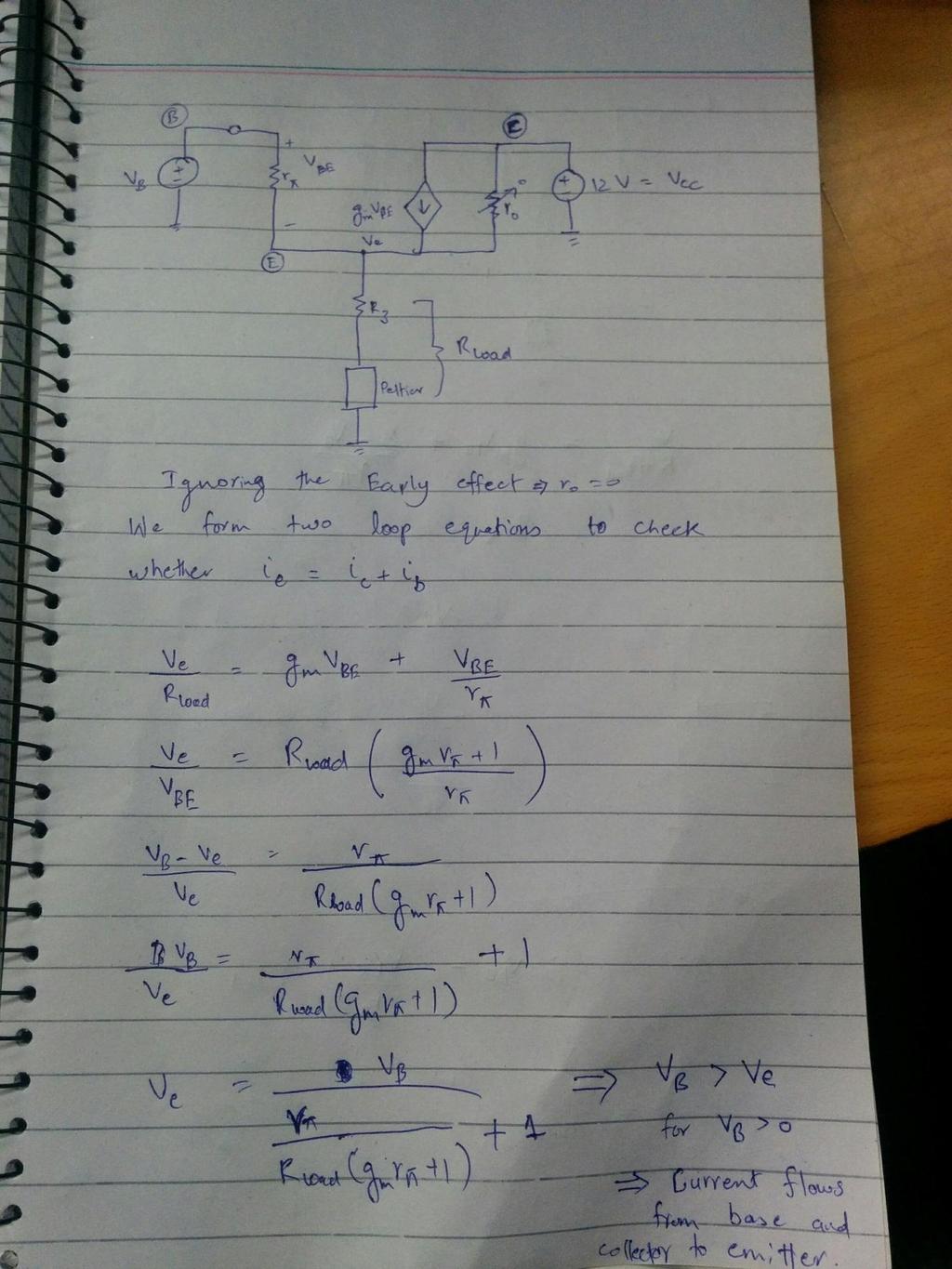
6
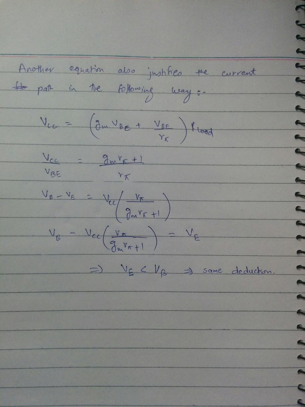
7
8 At this stage, it is convincing why the op-amp-transistor scheme is plausible for voltage to current amplification. A DAQ (NI-USB 6001) is used as the control element: referring to Figure 1, THERM SOURCE is connected to a small supply from a DAQ output port. The thermistor is connected in the THERM BLOCK. The thermistor voltage is fed to the DAQ input via V_THERM outlet. This is used by a LabVIEW to generate a control signal at its output i.e. the INPUT BLOCK. The idea is to feed the instantaneous temperature of the device to a PI control algorithm and then the input is fed back to the circuit in accordance with a set point of the temperature. DAQ The control signal, called Vin in this report, is connected to the output of the DAQ (in our case it is terminal 0) and the voltage across the thermistor which is essentially the output is connected to the terminal 0 of the DAQ input. A 2V supply is connected to port 1 of the DAQ output for the thermistor. The + sign is the positive terminal and the arrow (and not the sign) is the ground. The terminal description is true for both input and output. Using NI Automation Explorer, the activity of the DAQ can be checked. VI and Front Panel So a control algorithm is applied using LabVIEW and an interface is developed to gauge the instantaneous temperature of the device. An NTC thermistor s Steinhart coefficients are calculated using curve fitting technique. These coefficients are named a, b and c in the VI. The first grey Formula Node is there to convert the commanded set point value of temperature to a set point voltage. Since the Steinhart coefficients are known, Steinhart equation is applied for the said conversion. A note must be made here. Several approaches such as dealing directly with temperature values may work just as well instead of converting temperature readings to voltages, and that several off-the-shelf VI are available for thermistor calibration, but in this VI all calculations are in voltages and the translation of voltage into temperature is done at the moment of exchange between VI and front panel. The variables excitation_v, exc_v and V_exc all refer to the voltage source value and this source would be connected to excite the thermistor in series with a resistor. There is a digitizing parameters control pallet, for adjusting the sampling rate. Now a DAQ Assistant could be used instead of these maroon VIs to configure the input and output terminals, but here this is gives more control over the procedure. Before moving to the MathScript, the purpose of the second grey Formula Node is discussed. It is just there to translate instantaneous thermistor voltage to instantaneous device temperature. The former is calculated via a simple circuital loop analysis. In the MathScript lies the core of the VI-a code for PI algorithm. The first line calculates the error between set point temperature and the instantaneous temperature. The blue i at the bottom left of the while loop is the count for number of iterations. A check is made to see if it s the first iteration so as to erase garbage and reset error memory to zero. If it s not the first iteration, the error adds up. This
9 section serves as the integration of error as followed by the generic feedback equation. For the proportional part, the error is just multiplied by a constant. This generates the control signal Vin. At the end of each iteration, the function of e_previous=mem is performed by the yellow box and the two variables at the top of blue case. This is how the sum of error is kept updated for next iteration. Again, the check for stop button comes into place. The variable stop_command acts as the alarm running throughout the VI. The control signal Vin is turned off, and stop command updates the red stop button of the while loop. Observations, explanations and frame of conduct The system is designed for a specific temperature range which is 20 deg C to 100 deg C. This means that parameters such as P, I, and sampling frequency have been tuned with the DAQ output voltage limitations such that if the set point is the extreme of our desired temperature range, the overshoot of the control signal coming through the limited DAQ output stays well within range of the DAQ output voltage. Therefore there is only a certain flexibility that is available in changing these parameters. The VI does not validate this fact when the set parameter values are set. One has to be considerate of choosing the optimal values. Of course, this lack of flexibility makes the process slow but it is safer. To describe this behavior, following two figures are shown. One depicts lesser overshoot and the other depicts more overshoot with lesser time taken.please note that these two graphs were obtained when real-timechange-of-set-point feature was not installed in the VI which would put more constraints on changing value of the parameters. It is recommended that these parameters may not be changed (in the actual VI) from what values are going to be prescribed in the discussion that follows. A faster VI can be made if the temperature set point control is taken out of the while loop of the VI. With this, real time change of set point feature would be lost.

10 Figure 4: 100 deg C profile with lesser overshoot Figure 5: 50 deg profile with higher overshoot Another feature in the VI which squeezes the flexibility in changing parameters, and hence causes the process to be slower, is that the temperature control is dynamic. Dynamic means that user can change the temperature set-point while the VI is running and approaching a different set point. The fact that this almost fixates the parameter values is first described and then explained below. Suppose user commands the VI to set the peltier temperature to 70 deg C. The front panel looks like the following figure.


11 Figure 6: 50 deg C profile Now suppose the temperature set-point was changed to 100 deg C while the program was running and the temperature was maintained at 50 deg C initially. One does that by simply changing the value under the temp set point (C) control on the front panel and then clicking anywhere on the screen. Following behavior is seen. No other parameters were disturbed.
12 Figure 7: 50 deg C to 100 deg C profile Now suppose a different set point for a change. Suppose the temperature set point is 75 deg C in steady state and user changes the temperature setpoint to 25 deg C. Two different things happen if different values of P, I and sampling frequency are used. These two different scenarios are depicted in the following two figures.


13 Figure 8: Unexpected scenario for a certain sampling frequency Figure 9: Correct scenario for a different suitable sampling frequency This demonstrates the dynamic behavior that is occurring in the system. The focus point is the temperature set point changing from 75 to 25 deg C. Now two independent elements are trying to lower the temperature: the device cooling down itself loosing heat to the surrounding in pursuit of thermal equilibrium and second, the VI changing the control signal. As shown in the unexpected scenario, with a certain sampling frequency, the temperature does not go to 25 deg C but instead starts increasing at 32 deg C. This error is because of program constraints: if the program is not sampling the values right, the command signal is going to stray away from the target. Here is why. Temperature is partly automatically decreasing without the VI. Initially, the natural temperature downfall is greater than the VI s command signal. This is because VI s parameters are small compared to what we may refer to as nature s parameters. It takes a while for the VI to execute. The instance between the sample taken and the code execution and control signal generation is of utmost
14 importance. Suppose the sample was taken to be 45 deg C, and it took 10 ms for the code to execute and generate an error based on that sample which may not even be the temperature of the device after those 10 ms. This mismatch leads to inaccurate control signal generation. Therefore, the less frequent the sample taken the lesser the VI reacts and lesser the mismatch in that particular time and temperature scale. Additional support material Warm up and precautions Connect the DAQ terminals as shown in the DAQ connection section s figure below. Check DAQ s activity using NI Automation Explorer. Connect the power supplies as labelled. Before turning on any power supply, make sure the current swing is not at the limiting position. Make sure no stripped wires touch each other during the whole process. Make sure the supplies are properly made into +12V and - 12V. Regarding negative banana clips, connect them to the negative sign terminals written on the battery ports and not the ground sign terminals written on the battery port, since this is a dual supply with one customized common ground (for explanation scroll above). Open LabVIEW. Set the desired temperature of the device less than or equal to 100 deg C. Keep P=0.05, I=0.05, sampling frequency=1, number of samples=10. Press Run and not Run continuously option in the VI and wait for the device to achieve steady state, until stop button needs to be pressed. Keep an eye on the current being drawn from the battery. After powering up the circuit and before running the VI, the current drawn must not be greater than 0.05 A from any of the two terminals. After running the VI, current is drawn from one of the battery terminals and the other terminal stays at nominal value of around 0.03 A.The terminal from which the current is drawn is seen to increase slowly upto a maximum of 1.3 A if setpoint is 100 deg C and the surrounding temperature from where the peltier took off is 22 deg C. So if too much current is being drawn from the terminals before or during the running VI, press the stop button and turn off the power supply. Look for any short connection while connecting wires and if the problem still persists, check for worn-out soldering of transistors, typically.also, the VI is designed for a particular face of peltier. If after starting the peltier, the results are opposite, it means the thermistor needs to be placed on the other face. DAQ connections The original picture is attached with the main folder for a more readable version.

15 Figure 10: DAQ connections Making a dual polarity power supply from independent power supplies To make a dual power supply, consider a toy which needs two cells. We connect the two cells together by joining one positive end with the other s negative end. The other ends of course go to the toy s labelled ends accordingly. The same principal is applied in a power supply. Some power supplies come with series and parallel option but the method prescribed here applies also to those with no such option. Just make sure that while applying this method, the supply is at independent mode, which means the terminals on the supply (if more than one) or two single terminal supplies are not internally connected in any way. Now, connect for example, the right side terminal s negative to the left side terminal s positive. A common ground has been established. Now as one swings both the terminals to let s say 5V, both terminals positives are 5V higher with reference to their originals ground terminals. But since the left terminal s positive was connected to right terminal s negative, the right terminal s positive was bound to be 5V higher and the left terminal s negative was bound to be 5V lower than the new ground. Hence the right terminal s positive is +5V and the left terminal s negative is -5V. One might as well argue that the left terminal s negative is 0V, the ground being at 5V and the right most terminal s positive at +10V, which is absolutely fine. It is the voltage difference that is of the essence.


16 Figure 11: Dual Power Supply connections Updates in the system In this phase of the work, we set out to explore the precise reason why the system was not cooling down to low enough temperatures. It turns out that the Peltier device needs proper cooling to behave the way it is meant to. A new fan was installed whose effects on achieving low cooling setpoints were quite evident. Below is an image of the new cooling system.
17 Figure 12: The new cooling system is essential for optimum device behavior Moreover, we also modified the circuit diagram as shown in Figure 1, in order to increase the gain of the overall sense signal. This would help in sending a larger signal at the base of the transistors, hence drawing more current against same control signal value. This was needed to achieve set-points quickly against the same PI values. In order to find out the optimum PI values against the range of temperature, manual tuning seemed suggestive. Here is a table that may give an idea of the trend followed by the system against changes in P and I values. The first row is recommended and is set as a reference for the rest of the rows, especially when comparing time taken to reach stability. Temperature Reference to Set point (C) P I Maximum Overshoot (C) Time taken to stabilize (s) at 20kHz 20 to Stable with ±0.13 C oscillations, takes time 0.6t 20 to Greater than 2t 20 to t 20 to Greater than 2t 20 to Greater than 2t 20 to Greater than 2t Table: System behavior against changes in P,I values
Experiment 9. PID Controller
 Experiment 9 PID Controller Objective: - To be familiar with PID controller. - Noting how changing PID controller parameter effect on system response. Theory: The basic function of a controller is to execute
Thermal Monitor. PI Feedback TL074. Opamp #3. Set Point Monitor. Figure 1. PI temperature control servolock circuit.
 References. [1] K.B. MacAdam, A. Steinback and C. Wieman. A narrow-band tunable diode laser system with grating feedback, and a saturated absorption spectrometer for Cs and Rb. Am. J. Phys. 60, 1098 (1992).
Discrete Op-Amp Kit MitchElectronics 2019
 Discrete Op-Amp Kit MitchElectronics 2019 www.mitchelectronics.co.uk CONTENTS Introduction 3 Schematic 4 How It Works 5 Materials 9 Construction 10 Important Information 11 Page 2 INTRODUCTION Even if
-binary sensors and actuators (such as an on/off controller) are generally more reliable and less expensive
 are generally more reliable and less expensive") Process controls are necessary for designing safe and productive plants. A variety of process controls are used to manipulate processes, however the most simple and often most effective is the PID controller.
Process controls are necessary for designing safe and productive plants. A variety of process controls are used to manipulate processes, however the most simple and often most effective is the PID controller.
1. Consider the closed loop system shown in the figure below. Select the appropriate option to implement the system shown in dotted lines using
 1. Consider the closed loop system shown in the figure below. Select the appropriate option to implement the system shown in dotted lines using op-amps a. b. c. d. Solution: b) Explanation: The dotted
Analog I/O. ECE 153B Sensor & Peripheral Interface Design Winter 2016
 Analog I/O ECE 153B Sensor & Peripheral Interface Design Introduction Anytime we need to monitor or control analog signals with a digital system, we require analogto-digital (ADC) and digital-to-analog
TC LV-Series Temperature Controllers V1.01
 TC LV-Series Temperature Controllers V1.01 Electron Dynamics Ltd, Kingsbury House, Kingsbury Road, Bevois Valley, Southampton, SO14 OJT Tel: +44 (0) 2380 480 800 Fax: +44 (0) 2380 480 801 e-mail support@electrondynamics.co.uk
Amplification. Objective. Equipment List. Introduction. The objective of this lab is to demonstrate the basic characteristics an Op amplifier.
 Amplification Objective The objective of this lab is to demonstrate the basic characteristics an Op amplifier. Equipment List Introduction Computer running Windows (NI ELVIS installed) National Instruments
ECE 203 LAB 6: INVERTED PENDULUM
 Version 1.1 1 of 15 BEFORE YOU BEGIN EXPECTED KNOWLEDGE Basic Circuit Analysis EQUIPMENT AFG Oscilloscope Programmable Power Supply MATERIALS Three 741 Opamps TIP41 NPN power transistor TIP42 PNP power
Digital Control of MS-150 Modular Position Servo System
 IEEE NECEC Nov. 8, 2007 St. John's NL 1 Digital Control of MS-150 Modular Position Servo System Farid Arvani, Syeda N. Ferdaus, M. Tariq Iqbal Faculty of Engineering, Memorial University of Newfoundland
Using LTSPICE to Analyze Circuits
 Using LTSPICE to Analyze Circuits Overview: LTSPICE is circuit simulation software that automatically constructs circuit equations using circuit element models (built in or downloadable). In its modern
Inverting input R 2. R 1 Output
 nalogue Electronics 8: Feedback and Op mps Last lecture we introduced diodes and transistors and an outline of the semiconductor physics was given to understand them on a fundamental level. We use transistors
Component modeling. Resources and methods for learning about these subjects (list a few here, in preparation for your research):
:") Component modeling This worksheet and all related files are licensed under the Creative Commons Attribution License, version 1.0. To view a copy of this license, visit http://creativecommons.org/licenses/by/1.0/,
Component modeling This worksheet and all related files are licensed under the Creative Commons Attribution License, version 1.0. To view a copy of this license, visit http://creativecommons.org/licenses/by/1.0/,
Speed Feedback and Current Control in PWM DC Motor Drives
 Exercise 3 Speed Feedback and Current Control in PWM DC Motor Drives EXERCISE OBJECTIVE When you have completed this exercise, you will know how to improve the regulation of speed in PWM dc motor drives.
HEAT ACTIVATED SWITCH KIT
 TEACHING RESOURCES SCHEMES OF WORK DEVELOPING A SPECIFICATION COMPONENT FACTSHEETS HOW TO SOLDER GUIDE REACT TO THE TEMPERATURE WITH THIS HEAT ACTIVATED SWITCH KIT Version 2.1 Heat Activated Switch Teaching
UNIT 4 BIASING AND STABILIZATION
 UNIT 4 BIASING AND STABILIZATION TRANSISTOR BIASING: To operate the transistor in the desired region, we have to apply external dec voltages of correct polarity and magnitude to the two junctions of the
CSE 3215 Embedded Systems Laboratory Lab 5 Digital Control System
 Introduction CSE 3215 Embedded Systems Laboratory Lab 5 Digital Control System The purpose of this lab is to introduce you to digital control systems. The most basic function of a control system is to
Feedback Systems in HVAC ASHRAE Distinguished Lecture Series Jim Coogan Siemens Building Technologies
 Feedback Systems in HVAC ASHRAE Distinguished Lecture Series Jim Coogan Siemens Building Technologies ASHRAE, Madison Chapter October, 2014 Agenda Definitions: feedback and closed-loop control Types of
Feb. 1, 2013 TEC controller design experts offer tips to lower the cost and simplify the design of the devices, and to increase their ease of use.
 Thermoelectric Cooler Controller Design Made Simpler Gang Liu, Can Li and Fang Liu, Analog Technologies, Inc. Feb. 1, 2013 TEC controller design experts offer tips to lower the cost and simplify the design
OVEN INDUSTRIES, INC. Model 5C7-362
 OVEN INDUSTRIES, INC. OPERATING MANUAL Model 5C7-362 THERMOELECTRIC MODULE TEMPERATURE CONTROLLER TABLE OF CONTENTS Features... 1 Description... 2 Block Diagram... 3 RS232 Communications Connections...
DC Bias. Graphical Analysis. Script
 Course: B.Sc. Applied Physical Science (Computer Science) Year & Sem.: Ist Year, Sem - IInd Subject: Electronics Paper No.: V Paper Title: Analog Circuits Lecture No.: 3 Lecture Title: Analog Circuits
APPLICATION NOTE AN-009. GaN Essentials. AN-009: Bias Sequencing and Temperature Compensation for GaN HEMTs
 GaN Essentials AN-009: Bias Sequencing and Temperature Compensation for GaN HEMTs NITRONEX CORPORATION 1 OCTOBER 2008 GaN Essentials: Bias Sequencing and Temperature Compensation of GaN HEMTs 1. Table
Laboratory 8 Operational Amplifiers and Analog Computers
 Laboratory 8 Operational Amplifiers and Analog Computers Introduction Laboratory 8 page 1 of 6 Parts List LM324 dual op amp Various resistors and caps Pushbutton switch (SPST, NO) In this lab, you will
TEMPERATURE PROCESS CONTROL MANUAL. Penn State Chemical Engineering
 TEMPERATURE PROCESS CONTROL MANUAL Penn State Chemical Engineering Revised Summer 2015 Contents LEARNING OBJECTIVES... 3 EXPERIMENTAL OBJECTIVES AND OVERVIEW... 3 Pre-lab study:... 3 Experiments in the
Summer 2015 Examination
 Summer 2015 Examination Subject Code: 17445 Model Answer Important Instructions to examiners: 1) The answers should be examined by key words and not as word-to-word as given in the model answer scheme.
Fast IC Power Transistor with Thermal Protection
 Fast IC Power Transistor with Thermal Protection Introduction Overload protection is perhaps most necessary in power circuitry. This is shown by recent trends in power transistor technology. Safe-area,
Chapter Two "Bipolar Transistor Circuits"
 Chapter Two "Bipolar Transistor Circuits" 1.TRANSISTOR CONSTRUCTION:- The transistor is a three-layer semiconductor device consisting of either two n- and one p-type layers of material or two p- and one
INDIANA UNIVERSITY, DEPT. OF PHYSICS, P400/540 LABORATORY FALL Laboratory #5: More Transistor Amplifier Circuits
 INDIANA UNIVERSITY, DEPT. OF PHYSICS, P400/540 LABORATORY FALL 2008 Laboratory #5: More Transistor Amplifier Circuits Goal: Use and measure the behavior of transistor circuits used to implement different
Electronics Prof D. C. Dube Department of Physics Indian Institute of Technology, Delhi
 Electronics Prof D. C. Dube Department of Physics Indian Institute of Technology, Delhi Module No. # 04 Feedback in Amplifiers, Feedback Configurations and Multi Stage Amplifiers Lecture No. # 03 Input
EXPERIMENT 12: SIMULATION STUDY OF DIFFERENT BIASING CIRCUITS USING NPN BJT
 EXPERIMENT 12: SIMULATION STUDY OF DIFFERENT BIASING CIRCUITS USING NPN BJT AIM: 1) To study different BJT DC biasing circuits 2) To design voltage divider bias circuit using NPN BJT SOFTWARE TOOL: PC
Integrated Circuit: Classification:
 Integrated Circuit: It is a miniature, low cost electronic circuit consisting of active and passive components that are irreparably joined together on a single crystal chip of silicon. Classification:
CHAPTER 7 HARDWARE IMPLEMENTATION
 168 CHAPTER 7 HARDWARE IMPLEMENTATION 7.1 OVERVIEW In the previous chapters discussed about the design and simulation of Discrete controller for ZVS Buck, Interleaved Boost, Buck-Boost, Double Frequency
Carleton University ELEC Lab 1. L2 Friday 2:30 P.M. Student Number: Operation of a BJT. Author: Adam Heffernan
 Carleton University ELEC 3509 Lab 1 L2 Friday 2:30 P.M. Student Number: 100977570 Operation of a BJT Author: Adam Heffernan October 13, 2017 Contents 1 Transistor DC Characterization 3 1.1 Calculations
EE 300W Lab 2: Optical Theremin Critical Design Review
 EE 300W Lab 2: Optical Theremin Critical Design Review Team Drunken Tinkers: S6G8 Levi Nicolai, Harvish Mehta, Justice Lee October 21, 2016 Abstract The objective of this lab is to create an Optical Theremin,
Data Conversion and Lab Lab 1 Fall Operational Amplifiers
 Operational Amplifiers Lab Report Objectives Materials See separate report form located on the course webpage. This form should be completed during the performance of this lab. 1) To construct and operate
Short Channel Bandgap Voltage Reference
 Short Channel Bandgap Voltage Reference EE-584 Final Report Authors: Thymour Legba Yugu Yang Chris Magruder Steve Dominick Table of Contents Table of Figures... 3 Abstract... 4 Introduction... 5 Theory
Chapter 13: Introduction to Switched- Capacitor Circuits
 Chapter 13: Introduction to Switched- Capacitor Circuits 13.1 General Considerations 13.2 Sampling Switches 13.3 Switched-Capacitor Amplifiers 13.4 Switched-Capacitor Integrator 13.5 Switched-Capacitor
Temperature Monitoring and Fan Control with Platform Manager 2
 August 2013 Introduction Technical Note TN1278 The Platform Manager 2 is a fast-reacting, programmable logic based hardware management controller. Platform Manager 2 is an integrated solution combining
CHARACTERIZATION OF OP-AMP
 EXPERIMENT 4 CHARACTERIZATION OF OP-AMP OBJECTIVES 1. To sketch and briefly explain an operational amplifier circuit symbol and identify all terminals. 2. To list the amplifier stages in a typical op-amp
IMPLEMENTATION AND DESIGN OF TEMPERATURE CONTROLLER UTILIZING PC BASED DATA ACQUISITION SYSTEM
 www.elkjournals.com IMPLEMENTATION AND DESIGN OF TEMPERATURE CONTROLLER UTILIZING PC BASED DATA ACQUISITION SYSTEM Ravindra Mishra ABSTRACT Closed loop or Feedback control is a popular way to regulate
Chapter 3-2 Semiconductor devices Transistors and Amplifiers-BJT Department of Mechanical Engineering
 MEMS1082 Chapter 3-2 Semiconductor devices Transistors and Amplifiers-BJT Bipolar Transistor Construction npn BJT Transistor Structure npn BJT I = I + E C I B V V BE CE = V = V B C V V E E Base-to-emitter
Basic Operational Amplifier Circuits
 Basic Operational Amplifier Circuits Comparators A comparator is a specialized nonlinear op-amp circuit that compares two input voltages and produces an output state that indicates which one is greater.
EXPERIMENT #3 TRANSISTOR BIASING
 EXPERIMENT #3 TRANSISTOR BIASING Bias (operating point) for a transistor is established by specifying the quiescent (D.C., no signal) values of collector-emitter voltage V CEQ and collector current I CQ.
MASSACHUSETTS INSTITUTE OF TECHNOLOGY Hands-On Introduction to EE Lab Skills Laboratory No. 2 BJT, Op Amps IAP 2008
 Name MASSACHUSETTS INSTITUTE OF TECHNOLOGY 6.09 Hands-On Introduction to EE Lab Skills Laboratory No. BJT, Op Amps IAP 008 Objective In this laboratory, you will become familiar with a simple bipolar junction
Dr. Charles Kim ELECTRONICS I. Lab 5 Bipolar Junction Transistor (BJT) I TRADITIONAL LAB
 I TRADITIONAL LAB") ELECTRONICS I Lab 5 Bipolar Junction Transistor (BJT) I TRADITIONAL LAB MOBILE STUDIO LAB Before We Start A transistor is a 3-terminal device available in two configurations, NPN and PNP. The transistor
ELECTRONICS I Lab 5 Bipolar Junction Transistor (BJT) I TRADITIONAL LAB MOBILE STUDIO LAB Before We Start A transistor is a 3-terminal device available in two configurations, NPN and PNP. The transistor
Temperature activated switch
 Build instructions, circuit explanation and example applications Issue 1.5 Product information: www.kitronik.co.uk/quicklinks/2113/ TEACHER Temperature activated switch Introduction About the project kit
Field Effect Transistors
 Field Effect Transistors Purpose In this experiment we introduce field effect transistors (FETs). We will measure the output characteristics of a FET, and then construct a common-source amplifier stage,
Prelab: Introduction and Greenhouse Construction
 Prelab: Introduction and Greenhouse Construction In this lab, you will create a PID control system that will regulate temperature and humidity of a greenhouse-like enclosure. You will learn the concepts
Introduction To Temperature Controllers
 Introduction To Temperature Controllers The Miniature CN77000 is a full featured microprocessor-based controller in a 1/16 DIN package. How Can I Control My Process Temperature Accurately and Reliably?
EET 438a Automatic Control Systems Technology Laboratory 1 Analog Sensor Signal Conditioning
 EET 438a Automatic Control Systems Technology Laboratory 1 Analog Sensor Signal Conditioning Objectives: Use analog OP AMP circuits to scale the output of a sensor to signal levels commonly found in practical
Experiment 8: Semiconductor Devices
 Name/NetID: Experiment 8: Semiconductor Devices Laboratory Outline In today s experiment you will be learning to use the basic building blocks that drove the ability to miniaturize circuits to the point
3 Circuit Theory. 3.2 Balanced Gain Stage (BGS) Input to the amplifier is balanced. The shield is isolated
 Input to the amplifier is balanced. The shield is isolated") Rev. D CE Series Power Amplifier Service Manual 3 Circuit Theory 3.0 Overview This section of the manual explains the general operation of the CE power amplifier. Topics covered include Front End Operation,
Rev. D CE Series Power Amplifier Service Manual 3 Circuit Theory 3.0 Overview This section of the manual explains the general operation of the CE power amplifier. Topics covered include Front End Operation,
ES 330 Electronics II Homework # 2 (Fall 2016 Due Wednesday, September 7, 2016)
") Page1 Name ES 330 Electronics II Homework # 2 (Fall 2016 Due Wednesday, September 7, 2016) Problem 1 (15 points) You are given an NMOS amplifier with drain load resistor R D = 20 k. The DC voltage (V RD
Page1 Name ES 330 Electronics II Homework # 2 (Fall 2016 Due Wednesday, September 7, 2016) Problem 1 (15 points) You are given an NMOS amplifier with drain load resistor R D = 20 k. The DC voltage (V RD
A SOFTWARE-BASED GAIN SCHEDULING OF PID CONTROLLER
 A SOFTWARE-BASED GAIN SCHEDULING OF PID CONTROLLER Hussein Sarhan Department of Mechatronics Engineering, Faculty of Engineering Technology, Amman, Jordan ABSTRACT In this paper, a scheduled-gain SG-PID
King Fahd University of Petroleum and Minerals. Department of Electrical Engineering
 King Fahd University of Petroleum and Minerals Department of Electrical Engineering AN OPEN LOOP RATIONAL SPEED CONTROL OF COOLING FAN UNDER VARYING TEMPERATURE Done By: Al-Hajjaj, Muhammad Supervised
In-Class Exercises for Lab 2: Input and Output Impedance
 In-Class Exercises for Lab 2: Input and Output Impedance. What is the output resistance of the output device below? Suppose that you want to select an input device with which to measure the voltage produced
HIGH LOW Astable multivibrators HIGH LOW 1:1
 1. Multivibrators A multivibrator circuit oscillates between a HIGH state and a LOW state producing a continuous output. Astable multivibrators generally have an even 50% duty cycle, that is that 50% of
How to Wire an Inverting Amplifier Circuit
 How to Wire an Inverting Amplifier Circuit Figure 1: Inverting Amplifier Schematic Introduction The purpose of this instruction set is to provide you with the ability to wire a simple inverting amplifier
Video Course on Electronics Prof. D. C. Dube Department of Physics Indian Institute of Technology, Delhi
 Video Course on Electronics Prof. D. C. Dube Department of Physics Indian Institute of Technology, Delhi Module No. # 02 Transistors Lecture No. # 09 Biasing a Transistor (Contd) We continue our discussion
EITN90 Radar and Remote Sensing Lab 2
 EITN90 Radar and Remote Sensing Lab 2 February 8, 2018 1 Learning outcomes This lab demonstrates the basic operation of a frequency modulated continuous wave (FMCW) radar, capable of range and velocity
Chapter 7: Instrumentation systems
 Chapter 7: Instrumentation systems Learning Objectives: At the end of this topic you will be able to: describe the use of the following analogue sensors: thermistors strain gauge describe the use of the
Current Mirrors. Basic BJT Current Mirror. Current mirrors are basic building blocks of analog design. Figure shows the basic NPN current mirror.
 Current Mirrors Basic BJT Current Mirror Current mirrors are basic building blocks of analog design. Figure shows the basic NPN current mirror. For its analysis, we assume identical transistors and neglect
Temperature Monitoring and Fan Control with Platform Manager 2
 Temperature Monitoring and Fan Control September 2018 Technical Note FPGA-TN-02080 Introduction Platform Manager 2 devices are fast-reacting, programmable logic based hardware management controllers. Platform
Testing and Stabilizing Feedback Loops in Today s Power Supplies
 Keywords Venable, frequency response analyzer, impedance, injection transformer, oscillator, feedback loop, Bode Plot, power supply design, open loop transfer function, voltage loop gain, error amplifier,
Physics 303 Fall Module 4: The Operational Amplifier
 Module 4: The Operational Amplifier Operational Amplifiers: General Introduction In the laboratory, analog signals (that is to say continuously variable, not discrete signals) often require amplification.
Small signal Amplifier stages. Figure 5.2 Classification of power amplifiers
 5.1 Introduction When the power requirement to drive the load is in terms of several Watts rather than mili-watts the power amplifiers are used. Power amplifiers form the last stage of multistage amplifiers.
EE320L Electronics I. Laboratory. Laboratory Exercise #2. Basic Op-Amp Circuits. Angsuman Roy. Department of Electrical and Computer Engineering
 EE320L Electronics I Laboratory Laboratory Exercise #2 Basic Op-Amp Circuits By Angsuman Roy Department of Electrical and Computer Engineering University of Nevada, Las Vegas Objective: The purpose of
LM125 Precision Dual Tracking Regulator
 LM125 Precision Dual Tracking Regulator INTRODUCTION The LM125 is a precision, dual, tracking, monolithic voltage regulator. It provides separate positive and negative regulated outputs, thus simplifying
Closed-Loop Speed Control, Proportional-Plus-Integral-Plus-Derivative Mode
 Exercise 7 Closed-Loop Speed Control, EXERCISE OBJECTIVE To describe the derivative control mode; To describe the advantages and disadvantages of derivative control; To describe the proportional-plus-integral-plus-derivative
Different Controller Terms
 Loop Tuning Lab Challenges Not all PID controllers are the same. They don t all use the same units for P-I-and D. There are different types of processes. There are different final element types. There
EE301 Electronics I , Fall
 EE301 Electronics I 2018-2019, Fall 1. Introduction to Microelectronics (1 Week/3 Hrs.) Introduction, Historical Background, Basic Consepts 2. Rewiev of Semiconductors (1 Week/3 Hrs.) Semiconductor materials
Operational amplifiers
 Chapter 8 Operational amplifiers An operational amplifier is a device with two inputs and one output. It takes the difference between the voltages at the two inputs, multiplies by some very large gain,
Operational Amplifiers
 Operational Amplifiers Table of contents 1. Design 1.1. The Differential Amplifier 1.2. Level Shifter 1.3. Power Amplifier 2. Characteristics 3. The Opamp without NFB 4. Linear Amplifiers 4.1. The Non-Inverting
CHAPTER 2 PID CONTROLLER BASED CLOSED LOOP CONTROL OF DC DRIVE
 23 CHAPTER 2 PID CONTROLLER BASED CLOSED LOOP CONTROL OF DC DRIVE 2.1 PID CONTROLLER A proportional Integral Derivative controller (PID controller) find its application in industrial control system. It
UNIT I - TRANSISTOR BIAS STABILITY
 UNIT I - TRANSISTOR BIAS STABILITY OBJECTIVE On the completion of this unit the student will understand NEED OF BIASING CONCEPTS OF LOAD LINE Q-POINT AND ITS STABILIZATION AND COMPENSATION DIFFERENT TYPES
An Improved Bandgap Reference (BGR) Circuit with Constant Voltage and Current Outputs
 Circuit with Constant Voltage and Current Outputs") International Journal of Research in Engineering and Innovation Vol-1, Issue-6 (2017), 60-64 International Journal of Research in Engineering and Innovation (IJREI) journal home page: http://www.ijrei.com
International Journal of Research in Engineering and Innovation Vol-1, Issue-6 (2017), 60-64 International Journal of Research in Engineering and Innovation (IJREI) journal home page: http://www.ijrei.com
ECE 363 FINAL (F16) 6 problems for 100 pts Problem #1: Fuel Pump Controller (18 pts)
 6 problems for 100 pts Problem #1: Fuel Pump Controller (18 pts)") ECE 363 FINAL (F16) NAME: 6 problems for 100 pts Problem #1: Fuel Pump Controller (18 pts) You are asked to design a high-side switch for a remotely operated fuel pump. You decide to use the IRF9520 power
ECE 363 FINAL (F16) NAME: 6 problems for 100 pts Problem #1: Fuel Pump Controller (18 pts) You are asked to design a high-side switch for a remotely operated fuel pump. You decide to use the IRF9520 power
Thermoelectric Temperature Control Using the isppac20
 September 2001 Overview Application Note AN6029 Temperature controls are found in many places, ranging from steel mills to the thermostat in your living room. This application note focuses on one particular
Last Time. P and N type semiconductors Diode internals Transistors NPN PNP
 Last Time P and N type semiconductors Diode internals Transistors NPN PNP Device of the Day... Piezo microphone Device of the Day... Transistor Recap Transistors operate as current amplifiers With the
SxWEB PID algorithm experimental tuning
 SxWEB PID algorithm experimental tuning rev. 0.3, 13 July 2017 Index 1. PID ALGORITHM SX2WEB24 SYSTEM... 2 2. PID EXPERIMENTAL TUNING IN THE SX2WEB24... 3 2.1 OPEN LOOP TUNING PROCEDURE... 3 2.1.1 How
Learning Objectives:
 Topic 5.4 Instrumentation Systems Learning Objectives: At the end of this topic you will be able to; describe the use of the following analogue sensors: thermistors and strain gauges; describe the use
Fundamentals of Servo Motion Control
 Fundamentals of Servo Motion Control The fundamental concepts of servo motion control have not changed significantly in the last 50 years. The basic reasons for using servo systems in contrast to open
Massachusetts Institute of Technology MIT
 Massachusetts Institute of Technology MIT Real Time Wireless Electrocardiogram (ECG) Monitoring System Introductory Analog Electronics Laboratory Guilherme K. Kolotelo, Rogers G. Reichert Cambridge, MA
Procidia Control Solutions Dead Time Compensation
 APPLICATION DATA Procidia Control Solutions Dead Time Compensation AD353-127 Rev 2 April 2012 This application data sheet describes dead time compensation methods. A configuration can be developed within
.dc Vcc Ib 0 50uA 5uA
 EE 2274 BJT Biasing PreLab: 1. Common Emitter (CE) Transistor Characteristics curve Generate the characteristics curves for a 2N3904 in LTspice by plotting Ic by sweeping Vce over a set of Ib steps. Label
Sensor Interfacing and Operational Amplifiers Lab 3
 Name Lab Day Lab Time Sensor Interfacing and Operational Amplifiers Lab 3 Introduction: In this lab you will design and build a circuit that will convert the temperature indicated by a thermistor s resistance
Final Project Stereo Audio Amplifier Final Report
 The George Washington University School of Engineering and Applied Science Department of Electrical and Computer Engineering Final Project Stereo Audio Amplifier Final Report Daniel S. Boucher ECE 20-32,
T6+ Analog I/O Section. Installation booklet for part numbers: 5/4-80A-115 5/4-90A-115 5/4-80A /4-90A-1224
 T and T+ are trade names of Trol Systems Inc. TSI reserves the right to make changes to the information contained in this manual without notice. publication /4A115MAN- rev:1 2001 TSI All rights reserved
Operational amplifiers
 Operational amplifiers Bởi: Sy Hien Dinh INTRODUCTION Having learned the basic laws and theorems for circuit analysis, we are now ready to study an active circuit element of paramount importance: the operational
AD596/AD597 SPECIFICATIONS +60 C and V S = 10 V, Type J (AD596), Type K (AD597) Thermocouple,
, Type K (AD597) Thermocouple,") AD597 SPECIFICATIONS (@ +60 C and V S = 10 V, Type J (AD596), Type K (AD597) Thermocouple, unless otherwise noted) Model AD596AH AD597AH AD597AR Min Typ Max Min Typ Max Min Typ Max Units ABSOLUTE MAXIMUM
AD597 SPECIFICATIONS (@ +60 C and V S = 10 V, Type J (AD596), Type K (AD597) Thermocouple, unless otherwise noted) Model AD596AH AD597AH AD597AR Min Typ Max Min Typ Max Min Typ Max Units ABSOLUTE MAXIMUM
Transistor Biasing. DC Biasing of BJT. Transistor Biasing. Transistor Biasing 11/23/2018
 Transistor Biasing DC Biasing of BJT Satish Chandra Assistant Professor Department of Physics P P N College, Kanpur www.satish0402.weebly.com A transistors steady state of operation depends a great deal
Oscillators. An oscillator may be described as a source of alternating voltage. It is different than amplifier.
 Oscillators An oscillator may be described as a source of alternating voltage. It is different than amplifier. An amplifier delivers an output signal whose waveform corresponds to the input signal but
5. Transducers Definition and General Concept of Transducer Classification of Transducers
 5.1. Definition and General Concept of Definition The transducer is a device which converts one form of energy into another form. Examples: Mechanical transducer and Electrical transducer Electrical A
Operational Amplifiers
 Operational Amplifiers November 23, 2017 1 Pre-lab Calculations 1) Calculate the gain for all four circuits in Fig. 3. 2 Introduction Operational Amplifiers? They should call them fun amplifiers. Because,
Practical Testing Techniques For Modern Control Loops
 VENABLE TECHNICAL PAPER # 16 Practical Testing Techniques For Modern Control Loops Abstract: New power supply designs are becoming harder to measure for gain margin and phase margin. This measurement is
TEC Controller Evaluation Board TECEV104
 TECEV0 TEC Controller Evaluation Board TECEV0 By Gang Liu BOARD DESCRIPTION The TEC controller evaluation board TECEV0 is consisted of a complete tuning and application circuit for driving a TEC. It can
ECE 454 Homework #1 Due 11/28/2018 This Wednesday In Lab
 ECE 454 Homework #1 Due 11/28/2018 This Wednesday In Lab Design the Darlington push-pull amplifier specified in Lab 1: You will build this amplifier for Lab 1 so use parts that are available in the lab.
3 ppm Ultra Wide Range Curvature Compensated Bandgap Reference
 1 3 ppm Ultra Wide Range Curvature Compensated Bandgap Reference Xiangyong Zhou 421002457 Abstract In this report a current mode bandgap with a temperature coefficient of 3 ppm for the range from -117
ASTABLE MULTIVIBRATOR
 555 TIMER ASTABLE MULTIIBRATOR MONOSTABLE MULTIIBRATOR 555 TIMER PHYSICS (LAB MANUAL) PHYSICS (LAB MANUAL) 555 TIMER Introduction The 555 timer is an integrated circuit (chip) implementing a variety of
Physics 309 Lab 3 Bipolar junction transistor
 Physics 39 Lab 3 Bipolar junction transistor The purpose of this third lab is to learn the principles of operation of a bipolar junction transistor, how to characterize its performances, and how to use