EVLA Front-End CDR. EVLA Ka-Band (26-40 GHz) Receiver
|
|
|
- Lucinda Webster
- 5 years ago
- Views:
Transcription
")
1 EVLA Front-End CDR EVLA Ka-Band (26-40 GHz) Receiver 1
2 EVLA Ka-Band Receiver Overview 1) General Description 2) Block Diagram 3) Noise & Headroom Model 4) Feed & Thermal Gap 5) RF Tree - Phase-Shifter - OMT - LNA s 6) Prototype Component Tests - W/G Dewar Penetration - Calibration Path 7) Block Converter MMIC Module 8) Project Status 2
3 General Description The Ka-Band ( GHz) receiver provides a brand new frequency band for the VLA Relatively straightforward hybrid of existing K & Q-Band receiver designs Scaled K-Band Polarizer largely verified in the GBT 1cm receiver Waveguide output similar to Q-Band Dewar will be largely be based on the C-Band receiver design Utilizes novel MMIC-based Block Converter Potential future installation on the VLBA for tracking and navigation of deep space probes for NASA 3
4 EVLA Ka-Band Receiver Block Diagram Cryogenic Dewar Vacuum Window MMIC Module Key: WR-28 Waveguide Coaxial Cable, 2.9mm Coaxial Cable, SMA Cal Coupler RCP Coax to WG 35 db 2.9mm LNA Quartz Window WG to Coax GHz RF Post-Amp 15 db NF < 5 db x GHz IF Post-Amp 10 db NF < 2.5 db DC-18 GHz KaDCM RCP IF Output 8-18 GHz Mylar Window Transition 90 Phase Shifter 45 Twist OMT Noise Diode Magic Tee Termination or Pulse Cal Input LO Ref dbm LCP Cal Coupler Coax to WG 2.9mm 35 db LNA WG to Coax Quartz Window x3 NF < 5 db 15 db RF GHz Post-Amp GHz NF < 2.5 db 10 db IF Post-Amp KaDCM DC-18 GHz LCP IF Output 8-18 GHz 4
5 Ka-Band Block Conversion Frequency Diagram LO Ref = GHz IF Out 8-18 GHz Ka-Band Rx GHz GHz LO = 46.0 GHz Freq (GHz) Translation of GHz down to 8-18 GHz LO Ref GHz x 3 = 46 GHz Closest L301 Lock Point is actually GHz 5
6 Estimated EVLA Ka-Band T Rx, Output Power & Headroom EVLA Ka-Band Rx P (1dB) P (1%) Temp NF/C Loss/Gain Loss/Gain Delta T Trx BW Pnoise Pnoise Headroom (RHH : 28 March 2006) (dbm) (dbm) (K) (db) (db) (linear) (K) (K) (MHz) (dbm) dbm/ghz (db) for Tsky of 13.0 (K) Weather Window Feed Horn Vacuum Window Phase Shifter OMT Waveguide Cal Coupler (IL) Cal Coupler (Branch) Isolator LNA Stainless Steel W/G Vacuum Window Waveguide Isolator RF Post-Amp RF Filter (25-41 GHz) Attenuator RF Post-Amp Mixer (Level dB) IF Filter (DC-18 GHz) Post-Amp Attenuator Isolator
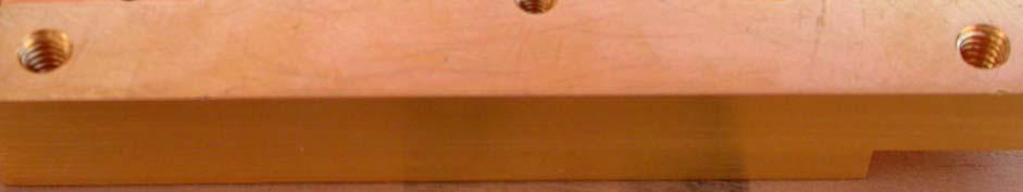
7 Ka-Band Feed 7

 Cryogenic Isolator Pamtech or Dorado CDL")

8 Ka-Band RF Tree Srikanth designed Ka-Band versions of Circular-to-Square Transition W/G Corrugated Phase-Shifter 45 Degree Twist Section Wollack Ortho-Mode Transducer NRAO Cal Coupler (not shown) Cryogenic Isolator Pamtech or Dorado CDL MAP-style LNA Output WR-28 waveguide path will need complicated bends & twists for alignment and thermal stress relief Prototype Rx will use flexguide 8
9 Ka-Band Srikanth Phase-Shifter Ka-Band Waveguide Phase-Shifter Differential Phase Shift S/N 1 (Smoothed) S/N 2 (Smoothed) Desired Phase Shift 1 db Axial Ratio Window Differential Phase Shift (Degrees) Differential Phase Shift (Degrees) Frequency (GHz) 9
10 Ka-Band Wollack-style OMT 10
11 CDL Ka-Band Low Noise Amplifiers Ka-Band Low Noise Amplifiers S/N AM017 Trx S/N AM017 Gain S/N AM018 Trx S/N AM018 Gain LNA Noise Temperature (K) ¹ LNA Gain (db) Frequency (GHz) 11


12 WR-28 Dewar Output Penetration Fixtures Rather than fabricate new WR-28 waveguide windows, we will reuse the commercial vacuum windows & custom-made dewar penetration fixtures preserved from the old A- Rack receiver package. The long-ago decommissioned VLA C- Band parametric amplifiers was once fed by a 32 GHz pump. We have managed to find about 116 units and 135 windows. More than enough for 30 EVLA and 11 VLBA receivers The supposedly narrowband units were found to have a surprisingly flat and low-loss broadband response. Less than 1 db across GHz 12
13 Dewar Penetration Insertion Loss Tests 3 Insertion Loss (db) Insertion Loss Measurements on WR-28 Signal Path Does not account for effects of LNA or Block Converter Module Impedance Match Vacuum Window (VW) Dewar Pentration (DP) + VW 6" SS Waveguide (SS6") + DP + VW SS6" + DP + VW + Isolator (Iso) 6" Flexguide (FG6") + SS6" + DP + VW FG6" + SS6" + DP + VW + Iso Frequency (MHz) 13
14 Ka-band Down- Converter Module (KaDCM) Ka-Band Downconverter Specifications: RF Frequency Range = GHz LO Frequency Range = GHz IF Frequency Range = 8-18 GHz RF to IF Gain = 14 +/- 2 db Noise Figure < 6.5 db Input P 1dB = -16 dbm LO Reference to IF leakage > -60 db 14
15 KaDCM Block Diagram RF Post-Amp GHz RF Post-Amp IF Post-Amp DC-18 GHz RF Input WR GHz 13 db NF < 5 db 5 db 13 db NF < 5 db 13 db NF < 2.5 db 3 db IF Output 8-18 GHz LO Ref dbm x3 Microstrip Filter GHz Waveguide Filter GHz KaDCM In theory, this design optimizes the RF-to-IF signal path to achieve maximum headroom while minimizing its noise contribution. 15
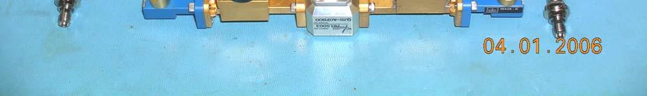
16 KaDCM Design The design of the Ka-band Down-Converter Module (KaDCM) was contracted out to the Microwave Group of Caltech s Electrical Engineering Department (i.e., Sandy Weinreb). The KaDCM design uses custom mixer and tripler MMIC s, designed by M. Morgan (now at CDL), which were fabricated on a United Monolithic Semiconductors (UMS) wafer. Caltech delivered a functioning first article KaDCM in Q3 2005, as well as a 2 nd assembled but untested unit, for use in the Ka- Band prototype receiver. Once the performance of the KaDCM has been verified, NRAO will fabricate the 66 units required for the EVLA receivers (and the 22 VLBA units, if needed) in-house. 16


17 KaDCM Block Exterior and Bias Card 17


18 KaDCM MMIC Channels & LO Filter 18
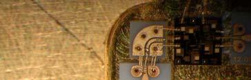
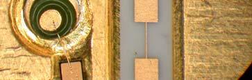
19 EVLA KaDCM Co-Planar W/G Circuit Board & MMIC Component Layout The KaDCM contains: - 7 MMIC Devices - 5 Amplifiers (Agilent) - 1 Custom Mixer (UMS) - 1 Custom Tripler (UMS) - 14 CPW boards - Approx 75 wire bonds 19
20 WR-28 Probe RF Filter GHz 1st RF 2nd RF Post-amp IF Post-amp Post-amp G=13 G=13 db db G=13 db Pad 5 db Microstrip GHz Filter Mixer LO Amp WR-22 Probe Pad 3 db WR-22 Probe LO Tripler LO Amplifier IF Output Connector IF Filter DC-18 GHz Thick Iris GHz WR-19 Waveguide Filter LO Input Connector 20
21 KaDCM Design Issues The LO to IF leakage specification proved to be the most difficult requirement to meet. The GHz LO reference can leak into the 8-18 GHz IF output range This type of direct coupling is minimized by a well designed physical layout A more subtle type of leakage arises from intermodulation products of the LO harmonics. For example, when the LO fundamental input is set to 16.0 GHz, the desired 3 rd harmonic of the LO reference will be 48.0 GHz while the 4 th will be at 64.0 GHz. If the mixer sees a strong 4 th harmonic, it will generate a 4 th minus 3 rd intermod which will exit the mixer at 16.0 GHz, right in the middle of the EVLA 8-18 GHz IF. Consequently the level of the unwanted 4 th harmonic must be strongly rejected. To mitigate the detrimental effect of this in continuum observations, the 4 th -3 rd LO leakage term (as determined by Barry Clark) must be 25 db below the broadband power in the 8-18 GHz IF. The estimated output level when looking at cold sky of the KaDCM IF is about -35 dbm. This means the 4 th -3 rd LO spur present in the IF will have to less than -60 dbm. Since the mixer requires an LO power level of +10 dbm at the desired 3 rd harmonic, the level of the unwanted 4 th harmonic will be about -10 dbm, assuming its power is down by -20 db. Balanced mixers typically have a 20 db rejection of signals on the LO port. Using a more conservative 15 db value, the resulting intermod level at the mixer IF port is about -25 dbm. With the 10 db IF postamp gain, the spur will be rise to -15 dbm, which is 45 db too high. 21
22 KaDCM Design Issues Thus to meet the -60 dbm spec, the level of the unwanted 4 th -3 rd LO leakage term at the mixer must be reduced by at least 45 db. To achieve this extra rejection, the output of the tripler requires an additional stage of filtering to reject the 4 th harmonic. A microstrip filter does not have a very high Q but has high out of band rejection. A waveguide filter has high Q but poor rejection at high frequencies where it becomes over-moded. The KaDCM utilizes a GHz microstrip filter followed by a Thick Iris GHz waveguide filter by (both designed by M. Morgan, NRAO-CDL). This cascaded filter is well matched to the desired GHz 3 rd harmonic. Note that in spectral line mode, when using a 10 KHz bandwidth, a level -41 db below noise power in the 8-18 GHz IF is ideally required. 22
23 LO Harmonic Filtering KaDCM Simulated LO Filter Insertion Loss Microstrip + Waveguide Filter Insertion Loss (db) MS Filter IL [db] WG Filter RL [db] nd 3 rd 4 th Frequency (GHz) 23
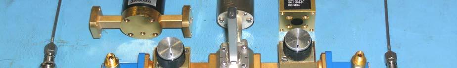
24 KaDCM Prototype #1 Conversion Gain vs. Frequency Simulated L301 Lock Points 20 Conversion Gain (db) KaDCM Prototype #1 Conversion Gain vs. Frequency Simulated L301 Lock Points for the LO reference (5 April 2006) LO Ref = GHz LO Ref = GHz LO Ref = GHz LO Ref = GHz LO Ref = GHz LO Ref = GHz LO Ref = GHz Frequency (GHz) 24
25 Spectrum Analyzer Measurement of KaDCM LO Ref Leakage LO Ref = 16 0 dbm & RF = Off (RHH : 5 April 2006) GHz = -91 dbm Output Power (dbm) Frequency (GHz) 25
26 KaDCM Headroom? Recent tests indicate that the prototype KaDCM does not achieve the expected compression level. Input power P(1dB) spec = -16 dbm Measured Input P(1dB) < -22 dbm Hopefully can play with RF & IF gains to mitigate the mixer compression. If this cannot be improved, it would adversly affect the Ka- Band Rx Headroom (defined as how far the typical operating point (i.e., cold sky) is below the 1% compression point). Would reduce current 21 db Headroom to 15 db Project Book Spec = 20 db 26
27 KaDCM Unit Cost Assumes minimum of 66 KaDCM units Direct Cost = $2,200 Indirect Cost = $5,000 if include pro-rated costs (with QPAM) of Caltech contract Wafers 50 GHz test equipment Wire bonder & accessories, etc. 27
28 Ka-Band Receiver Project Status Due to other pressures and diversions, the development of the Ka-Band receiver has been slower than originally planned. Most of the commercial components and custom waveguide components for the prototype system are in-house. Hope to complete the design, construction and evaluation of the prototype in Production slated to begin in Receivers will be built at or exceed the antenna outfitting schedule. 28
29 Questions? 29
30 Backup Slides 30


31 Thermal Gap Assembly (Q-Band Example) 31
32 Calibration Path Cal Coupler RCP LCP OMT Cal Coupler Coax to WG Coax to WG Noise Diode 35 db LNA 2.9mm 2.9mm 35 db LNA Quartz Window WG to Coax Magic Tee WG to Coax Quartz Window Termination Pulse Cal Pulse Cal Input Broadband Noise Source Magic Tee Splitter Separate Variable Attenuators From old A-Rack 32 GHz Paramp Have found 34 out of the 60 needed Will have to purchase the rest Hermetic 2.9 mm Coax Bulkhead Feedthru Connectors Commercial Stainless Steel Cables with K-Connectors VLA/GBT WR-28 Cal Couplers (30 db) Pulse/Phase Cal Option Desirable for VLBA Not needed on EVLA (use Termination) 32


33 Prototype Ka-Band Calibration Components 33
34 Magic Tee Test Results T Cal LCP & RCP Split (db) P Cal to T Cal Isolation (db) P Cal LCP & RCP Split (db) R. Hayward EVLA Front-End CDR EVLA Ka-Band Receiver Frequency (MHz). Quinstar Magic Tee QJH-A0FB00 (5 Dec 2004) LCP T Cal Power Split RCP T Cal Power Split P Cal to T Cal Isolation LCP P Cal Power Split RCP P Cal Power Split.. 34

35 35
36 Spectrum Analyzer Measurement of KaDCM LO Intermods LO Ref = 16 GHz & RF = 35 (5 April 2006) -20 LO-RF = = Output Power (dbm) RF-2 LO = = 9 2 RF-LO = = Frequency (GHz) 36
37 Spectrum Analyzer Measurement of KaDCM Output LO Ref = 16 GHz & Swept RF = GHz (5 April 2006) Output Power (dbm) Frequency (GHz) 37
EVLA Front-End CDR. Plans for S (2-4), X (8-12) & Ku (12-18 GHz) Receiver Bands
, X (8-12) & Ku (12-18 GHz) Receiver Bands") EVLA Front-End CDR Plans for S (2-4), X (8-12) & Ku (12-18 GHz) Receiver Bands 1 Contents S-Band Receiver EVLA Design X-Band Receiver EVLA Design EVLA Transition Ku-Band Receiver EVLA Design 2 EVLA S-Band
EVLA Front-End CDR Plans for S (2-4), X (8-12) & Ku (12-18 GHz) Receiver Bands 1 Contents S-Band Receiver EVLA Design X-Band Receiver EVLA Design EVLA Transition Ku-Band Receiver EVLA Design 2 EVLA S-Band
EVLA Front-End CDR. Overview & System Requirements
 EVLA Front-End CDR Overview & System Requirements 1 Overview & System Requirements Introduction to the EVLA Front-End Task EVLA vs. VLA Feeds Receivers System Requirements, including: System Temperatures
EVLA Receivers PDR. (4m, P,) L, S, C BAND RECEIVERS. AuthorDaniel (Mert) Mertely
 L, S, C BAND RECEIVERS. AuthorDaniel (Mert) Mertely") EVLA Receivers PDR (4m, P,) L, S, C BAND RECEIVERS Daniel (Mert) Mertely 1 Trx Projections EVLA RX FREQ RANGES AND OP TEMPS: REQUIRED vs. PROJECTED BND FRQ REQ CURNT CURNT CALC IDR RANGE Tsys (2) Tsys
EVLA Receivers PDR (4m, P,) L, S, C BAND RECEIVERS Daniel (Mert) Mertely 1 Trx Projections EVLA RX FREQ RANGES AND OP TEMPS: REQUIRED vs. PROJECTED BND FRQ REQ CURNT CURNT CALC IDR RANGE Tsys (2) Tsys
EVLA Receiver Issues. EVLA Advisory Committee Meeting, March 19-20, 2009
 EVLA Receiver Issues EVLA Advisory Committee Meeting, March 19-20, 2009 Robert Hayward - Systems Engineer for EVLA Front-Ends Gordon Coutts - Microwave Engineer, Front-End Group Sri Srikanth - Scientist/Research
Atacama Large Millimeter/submillimeter Array Expanded Very Large Array Robert C. Byrd Green Bank Telescope Very Long Baseline Array
 Atacama Large Millimeter/submillimeter Array Expanded Very Large Array Robert C. Byrd Green Bank Telescope Very Long Baseline Array A Planar OMT for the 8-12 GHz Receiver Front-End Michael Stennes October
EVLA Memo 60. The Circular Polarization Characteristics of the New VLA K-Band Receiver System
 EVLA Memo 6 The Circular Polarization Characteristics of the New VLA K-Band Receiver System Robert Hayward, Edward Szpindor, Darrell Hicks National Radio Astronomy Observatory 18 June 23 Abstract : The
EVLA Memo # 194 EVLA Ka-band Receiver Down Converter Module Harmonics: The Mega-Birdie at MHz
 EVLA Memo # 194 EVLA Ka-band Receiver Down Converter Module Harmonics: The Mega-Birdie at 29440 MHz R. Selina, E. Momjian, W. Grammer, J. Jackson NRAO February 5, 2016 Abstract Observations carried out
Ku-Band Receiver System for SHAO
 Ku-Band Receiver System for SHAO Overview Brent Willoughby July 2014 Atacama Large Millimeter/submillimeter Array Expanded Very Large Array Robert C. Byrd Green Bank Telescope Very Long Baseline Array
5 RECEIVERS TABLE TBD: EVLA RECEIVER FREQUENCY RANGES AND OPERATING TEMPERATURES
 EVLA Project Book, Chapter 5. 5 RECEIVERS Robert Hayward, Ed Szpindor, and Daniel J. Mertely Last changed 2001-Oct-30 Revision History 2001-July-01: Initial release. 2001-Oct-01: Sys-def & detail added.
K band Focal Plane Array: Mechanical and Cryogenic Considerations Steve White,Bob Simon, Mike Stennes February 20, 2008 COLD ELECTRONICS
 K band Focal Plane Array: Mechanical and Cryogenic Considerations Steve White,Bob Simon, Mike Stennes February 20, 2008 CRYOGENICS AND DEWAR DESIGN The dewar outside dimension must be less than the 36
Summary Report / EVLA FE PDR
 Summary Report / EVLA FE PDR This report is a summary of the findings of the EVLA FE PDR Review Panel and the responses by the Task Leader. The report is based on a top level presentation of the design
Millimeter Wave Product Catalogue VivaTech Consulting S.A.R.L.
 VivaTech Consulting S.A.R.L. sales@vivatech.biz Telephone: +33 04 89 01 14 61 Fax: +33 04 93 87 08 66 Table of Contents Millimeter Wave Low Noise Amplifiers VTLNA Series...3 Millimeter Wave Power Amplifiers
MICROWAVE MICROWAVE TRAINING BENCH COMPONENT SPECIFICATIONS:
 Microwave section consists of Basic Microwave Training Bench, Advance Microwave Training Bench and Microwave Communication Training System. Microwave Training System is used to study all the concepts of
Antennas and Receivers in Radio Astronomy
 Antennas and Receivers in Radio Astronomy Mark McKinnon Eleventh Synthesis Imaging Workshop Socorro, June 10-17, 2008 Outline 2 Context Types of antennas Antenna fundamentals Reflector antennas Mounts
Configuration of PNA-X, NVNA and X parameters
 Configuration of PNA-X, NVNA and X parameters VNA 1. S-Parameter Measurements 2. Harmonic Measurements NVNA 3. X-Parameter Measurements Introducing the PNA-X 50 GHz 43.5 GHz 26.5 GHz 13.5 GHz PNA-X Agilent
SERIES MXP BALANCED MIXERS FEATURES: APPLICATIONS: DESCRIPTION
 BALANCED MIXERS FEATURES: Low conversion loss and noise figure 13 dbm LO drive power Matched IF amplifier and LO offered Small, rugged package APPLICATIONS: DESCRIPTION Millitech series MXP balanced mixers
Design of a Sideband-Separating Balanced SIS Mixer Based on Waveguide Hybrids
 ALMA Memo 316 20 September 2000 Design of a Sideband-Separating Balanced SIS Mixer Based on Waveguide Hybrids S. M. X. Claude 1 and C. T. Cunningham 1, A. R. Kerr 2 and S.-K. Pan 2 1 Herzberg Institute
Platform Migration 8510 to PNA. Graham Payne Application Engineer Agilent Technologies
 Platform Migration 8510 to PNA Graham Payne Application Engineer Agilent Technologies We set the standard... 8410 8510 When we introduced the 8510, we changed the way S-parameter measurements were made!
RF Components Product Catalogue
 RF Components Product Catalogue Government and Defence Broadcast Marine, Oil and Gas SNG and VSAT RF Engineering by Design Contents Splitters / Combiners Active Splitters and Combiners Page 3 Passive Splitters
TECHNICAL INFORMATION
 TECHNICAL INFORMATION TECHNOLOGY Y-Junction circulator PORT 1 PORT 2 PORT 3 FIG. 1 The Y-junction circulator uses spinel ferrites or garnet ferrites in the presence of a magnetic bias field, to provide
CUSTOM INTEGRATED ASSEMBLIES
 17 CUSTOM INTEGRATED ASSEMBLIES CUSTOM INTEGRATED ASSEMBLIES Cougar offers full first-level integration capabilities, providing not just performance components but also full subsystem solutions to help
NATIONAL RADIO ASTRONOMY OBSERVATORY Socorro, NM ELECTRONICS DIVISION TECHNICAL NOTE NO. 217
 NATIONAL RADIO ASTRONOMY OBSERVATORY Socorro, NM ELECTRONICS DIVISION TECHNICAL NOTE NO. 217 Preliminary Measured Results of a Diagonal Quadruple-Ridged Ku-Band OMT Gordon Coutts November 29, 21 Preliminary
Dinesh Micro Waves & Electronics
 Wave Guide Components RECTANGULAR WAVE GUDES Dinesh Microwaves and Electronics manufacturers of high power waveguide in the microwaves industry, this experience had resulted in designing, manufacturing
10 GHz Power Combiner
 10 GHz Power Combiner More elegant, omitting Magic-T s 1 Introduction Agenda Traditional Method: Band-Combiner with 50 Ohm Load Narrow Band Solution The Goal of this Project Practical Design of a 10 GHz
Antennas & Receivers in Radio Astronomy Mark McKinnon. Twelfth Synthesis Imaging Workshop 2010 June 8-15
 Antennas & Receivers in Radio Astronomy Mark McKinnon 2010 June 8-15 Outline Context Types of antennas Antenna fundamentals Reflector antennas Mounts Optics Antenna performance Aperture efficiency Pointing
NATIONAL RADIO ASTRONOMY OBSERVATORY Green Bank, West Virginia Electronics Division Internal Report No 105
 NATIONAL RADIO ASTRONOMY OBSERVATORY Green Bank, West Virginia Electronics Division Internal Report No 105 CHARACTERIZATION TESTS OF THE WESTERN ELECTRIC PARAMETRIC AMPLIFIER Dennis Sweeney SEPTEMBER 1971
8.5 GHz to 13.5 GHz, GaAs, MMIC, I/Q Mixer HMC521ALC4
 11 7 8 9 FEATURES Downconverter, 8. GHz to 13. GHz Conversion loss: 9 db typical Image rejection: 27. dbc typical LO to RF isolation: 39 db typical Input IP3: 16 dbm typical Wide IF bandwidth: dc to 3.
MMA RECEIVERS: HFET AMPLIFIERS
 MMA Project Book, Chapter 5 Section 4 MMA RECEIVERS: HFET AMPLIFIERS Marian Pospieszalski Ed Wollack John Webber Last revised 1999-04-09 Revision History: 1998-09-28: Added chapter number to section numbers.
PARAMETER CONDITIONS TYPICAL PERFORMANCE Operating Supply Voltage 3.1V to 3.5V Supply Current V CC = 3.3V, LO applied 152mA
 DESCRIPTION LT5578 Demonstration circuit 1545A-x is a high linearity upconverting mixer featuring the LT5578. The LT 5578 is a high performance upconverting mixer IC optimized for output frequencies in
NATIONAL RADIO ASTRONOMY OBSERVATORY Socorro, NM ELECTRONICS DIVISION TECHNICAL NOTE NO. 217
 NATIONAL RADIO ASTRONOMY OBSERVATORY Socorro, NM ELECTRONICS DIVISION TECHNICAL NOTE NO. 217 Preliminary Measured Results of a Diagonal Quadruple-Ridged Ku-Band OMT Gordon Courts November 29,2010 Preliminary
Agilent N5250A PNA Millimeter-Wave Network Analyzer 10 MHz to 110 GHz
 Agilent N5250A PNA Millimeter-Wave Network Analyzer 10 MHz to 110 GHz Technical Overview High Performance Bench-Top Network Analyzer Maximize your frequency coverage with a single sweep from 10 MHz to
Millimeter Signal Measurements: Techniques, Solutions and Best Practices
 New Network Analyzer platform Millimeter Signal Measurements: Techniques, Solutions and Best Practices Phase Noise measurements update 1 N522XA PNA Series Network Analyzer Introducing Highest Performance
NATIONAL RADIO ASTRONOMY OBSERVATORY CHARLOTTESVILLE, VIRGINIA. ELECTRONICS DIVISION INTERNAL REPORT No. 275 CRYOGENIC, HEMT, LOW-NOISE RECEIVERS
 NATIONAL RADIO ASTRONOMY OBSERVATORY CHARLOTTESVILLE, VIRGINIA ELECTRONICS DIVISION INTERNAL REPORT No. 275 CRYOGENIC, HEMT, LOW-NOISE RECEIVERS FOR 1.3 TO 43 GHz RANGE S. WEINREB M. W. POSPIESZALSKI R.
ALMA Band-1: Key Components, Cartridge Design, and Test Plan
 ALMA Band-1: Key Components, Cartridge Design, and Test Plan Yuh-Jing Hwang, Chau-Ching Chiong, Yue-Fang Kuo, Ted Huang, Doug Henke, Marian Pospieszalski, Nicolas Reyes, Ciska Kemper, and Paul Ho ASIAA,
Application Note 5525
 Using the Wafer Scale Packaged Detector in 2 to 6 GHz Applications Application Note 5525 Introduction The is a broadband directional coupler with integrated temperature compensated detector designed for
EVLA Memo #119 Wide-Band Sensitivity and Frequency Coverage of the EVLA and VLA L-Band Receivers
 EVLA Memo #119 Wide-Band Sensitivity and Frequency Coverage of the EVLA and VLA L-Band Receivers Rick Perley and Bob Hayward January 17, 8 Abstract We determine the sensitivities of the EVLA and VLA antennas
Agilent Technologies PSA Series Spectrum Analyzers Test and Adjustment Software
 Test System Overview Agilent Technologies PSA Series Spectrum Analyzers Test and Adjustment Software Test System Overview The Agilent Technologies test system is designed to verify the performance of the
A 200 GHz Broadband, Fixed-Tuned, Planar Doubler
 A 200 GHz Broadband, Fixed-Tuned, Planar Doubler David W. Porterfield Virginia Millimeter Wave, Inc. 706 Forest St., Suite D Charlottesville, VA 22903 Abstract - A 100/200 GHz planar balanced frequency
Gain Lab. Image interference during downconversion. Images in Downconversion. Course ECE 684: Microwave Metrology. Lecture Gain and TRL labs
 Gain Lab Department of Electrical and Computer Engineering University of Massachusetts, Amherst Course ECE 684: Microwave Metrology Lecture Gain and TRL labs In lab we will be constructing a downconverter.
PNA Family Microwave Network Analyzers (N522x/3x/4xB) CONFIGURATION GUIDE
 CONFIGURATION GUIDE") PNA Family Microwave Network Analyzers (N522x/3x/4xB) CONFIGURATION GUIDE Table of Contents PNA Family Network Analyzer Configurations... 05 Test set and power configuration options...05 Hardware options...
PNA Family Microwave Network Analyzers (N522x/3x/4xB) CONFIGURATION GUIDE Table of Contents PNA Family Network Analyzer Configurations... 05 Test set and power configuration options...05 Hardware options...
AMPLIFIERS, ANTENNAS, MULTIPLIERS, SOURCES, WAVEGUIDE PRODUCTS MILLIMETER-WAVE COMPONENTS FERRITE PRODUCTS AND SUB-SYSTEMS
 AMPLIFIERS, ANTENNAS, MULTIPLIERS, SOURCES, WAVEGUIDE PRODUCTS MILLIMETER-WAVE COMPONENTS FERRITE PRODUCTS AND SUB-SYSTEMS 766 San Aleso Avenue, Sunnyvale, C A 94085 Tel. (408) 541-9226, Fax (408) 541-9229
3680 Series. Universal Test Fixtures. A Complete Measurement Solution. DC to 60 GHz DC to 20 GHz 3680K DC to 40 GHz 3680V DC to 60 GHz
 3680 Series Universal Test Fixtures DC to 60 GHz A Complete Measurement Solution 3680-20 DC to 20 GHz 3680K DC to 40 GHz 3680V DC to 60 GHz Solid ground contacts top and bottom allow microstrip or coplanar
Lightning D Vector Network Analyzers. Network Analysis Solutions for Design and Manufacturing. 40 MHz to 65 GHz
 Lightning 37000D Vector Network Analyzers 40 MHz to 65 GHz Network Analysis Solutions for Design and Manufacturing Vector Network Analyzers that offer... The 37000D Lightning Vector Network Analyzers are
Data Sheet SC5317 & SC5318A. 6 GHz to 26.5 GHz RF Downconverter SignalCore, Inc. All Rights Reserved
 Data Sheet SC5317 & SC5318A 6 GHz to 26.5 GHz RF Downconverter www.signalcore.com 2018 SignalCore, Inc. All Rights Reserved Definition of Terms 1 Table of Contents 1. Definition of Terms... 2 2. Description...
Agilent 83440B/C/D High-Speed Lightwave Converters
 Agilent 8344B/C/D High-Speed Lightwave Converters DC-6/2/3 GHz, to 6 nm Technical Specifications Fast optical detector for characterizing lightwave signals Fast 5, 22, or 73 ps full-width half-max (FWHM)
Millimeter- and Submillimeter-Wave Planar Varactor Sideband Generators
 Millimeter- and Submillimeter-Wave Planar Varactor Sideband Generators Haiyong Xu, Gerhard S. Schoenthal, Robert M. Weikle, Jeffrey L. Hesler, and Thomas W. Crowe Department of Electrical and Computer
Figure 1 Photo of an Upgraded Low Band Receiver
 NATIONAL RADIO ASTRONOMY OBSERVATORY SOCORRO, NEW MEXICO EVLA TECHNICAL REPORT #175 LOW BAND RECEIVER PERFORMANCE SEPTMBER 27, 2013 S.DURAND, P.HARDEN Upgraded low band receivers, figure 1, were installed
Micromachined microwave circuits at Birmingham. M J Lancaster P S Hall, P Gardner, F Huang, Y Wang, M Ke K Jiang, P Prewett
 Micromachined microwave circuits at Birmingham M J Lancaster P S Hall, P Gardner, F Huang, Y Wang, M Ke K Jiang, P Prewett Department of Electronic, Electrical and Computer Engineering and Department of
Revisions: jee Initial jee Corrected label on Figs 6 and 7, Updated Block Diagram
 Memorandum To: From: File John Effland Date: 5-5-2 Revisions: 5-5-2 jee Initial 5-5-16 jee Corrected label on Figs 6 and 7, Updated Block Diagram Subject: Comparison of Band 6 Cartridge Measurements in
Advanced Test Equipment Rentals ATEC (2832) Agilent 8510 System Solutions
 Agilent 8510 System Solutions") E stablished 1981 Advanced Test Equipment Rentals www.atecorp.com 800-404-ATEC (2832) Agilent 8510 System Solutions Your bridge to the future Application guide The guide below shows Agilent Technologies
E stablished 1981 Advanced Test Equipment Rentals www.atecorp.com 800-404-ATEC (2832) Agilent 8510 System Solutions Your bridge to the future Application guide The guide below shows Agilent Technologies
Vector Network Analyzer
 Vector Network Analyzer VNA Basics VNA Roadshow Budapest 17/05/2016 Content Why Users Need VNAs VNA Terminology System Architecture Key Components Basic Measurements Calibration Methods Accuracy and Uncertainty
AVN Training HartRAO 2016
 AVN Training HartRAO 2016 Microwave 1 Overview Introduction to basic components used in microwave receivers. Performance characteristics of these components. Assembly of components into a complete microwave
High Power RF MEMS Switch Technology
 High Power RF MEMS Switch Technology Invited Talk at 2005 SBMO/IEEE MTT-S International Conference on Microwave and Optoelectronics Conference Dr Jia-Sheng Hong Heriot-Watt University Edinburgh U.K. 1
Manufacturers of RF and Microwave Components and Assemblies Specialist in RF Filters, Power amplifiers and RF Switches
 Manufacturers of RF and Microwave Components and Assemblies Specialist in RF Filters, Power amplifiers and RF Switches sales@cormic.com www.cormic.com P 724.940.7556 F 724.940.7707 RF & MICROWAVE FILTERS
Ultra High Frequency Measurements
 Ultra High Frequency Measurements Desmond Fraser desmond@rheintech.com 703.689.0368 360 Herndon Parkway Suite 1400 Herndon, VA 20170 IEEE EMC DC / N. VA Chapter 31 January 2012 Overview We ll review Millimeter
Microwave. Accessories for Microwave Scalar and System Analyzers
 Microwave Accessories for Microwave Scalar and System Analyzers The following optional accessories are designed for use with the 6200B series of Microwave Test Sets, the 6820 series Scalar Analyzers and
Microwave Fundamentals A Survey of Microwave Systems and Devices p. 3 The Relationship of Microwaves to Other Electronic Equipment p.
 Microwave Fundamentals A Survey of Microwave Systems and Devices p. 3 The Relationship of Microwaves to Other Electronic Equipment p. 3 Microwave Systems p. 5 The Microwave Spectrum p. 6 Why Microwave
Receivers for. FFRF Tutorial by Tom Clark, NASA/GSFC & NVI Wettzell, March 19, 2009
 Receivers for VLBI2010 FFRF Tutorial by Tom Clark, NASA/GSFC & NVI Wettzell, March 19, 2009 There is no fundamental difference between the receivers for PRIME FOCUS & CASSEGRAIN Except for: the beamwidth
SHF Communication Technologies AG. Wilhelm-von-Siemens-Str. 23D Berlin Germany. Phone Fax
 SHF Communication Technologies AG Wilhelm-von-Siemens-Str. 23D 12277 Berlin Germany Phone +49 30 772051-0 Fax ++49 30 7531078 E-Mail: sales@shf.de Web: http://www.shf.de Datasheet SHF 100 BPP Broadband
Power Dividers, Couplers and Combiners
 , Inc. 2012 All rights reserved Power Dividers, Couplers and Combiners A Webinar Presented by Dr. Bob Froelich Of, Inc. November 20, 2012 Mini-Circuits Company Overview Founded: 1969 Headquarters: Brooklyn,
Defense Technical Information Center Compilation Part Notice
 UNCLASSIFIED Defense Technical Information Center Compilation Part Notice ADPO1 1752 TITLE: 220-320 GHz Harmonic Mixer for a Full Band Sweep Vector Network Analyzer DISTRIBUTION: Approved for public release,
71-86GHz Down-converter. GaAs Monolithic Microwave IC GLO DLO DRF GRF
 Conversion Gain (db) GaAs Monolithic Microwave IC Description The is a multifunction monolithic receiver, which integrates a balanced sub-harmonic cold FET mixer, a LO buffer, and a RF low noise amplifier.
ALMA MEMO #360 Design of Sideband Separation SIS Mixer for 3 mm Band
 ALMA MEMO #360 Design of Sideband Separation SIS Mixer for 3 mm Band V. Vassilev and V. Belitsky Onsala Space Observatory, Chalmers University of Technology ABSTRACT As a part of Onsala development of
GaAs MMIC Double Balanced Mixer. Description Package Green Status
 GaAs MMIC Double Balanced Mixer MM1-0212SSM 1. Device Overview 1.1 General Description The MM1-0212SSM is a highly linear GaAs MMIC double balanced mixer. MM1-0212SSM is a low frequency, high linearity
2 Gain Variation from the Receiver Output through the IF Path
 EVLA Memo #185 Bandwidth- and Frequency-Dependent Effects in the T34 Total Power Detector Keith Morris September 17, 214 1 Introduction The EVLA Intermediate Frequency (IF) system employs a system of power
Vector Network Analysis
 Portfolio Brochure Vector Network Analysis Product Portfolio Vector Network Analysis VNA Innovation Timeline In 1965, Anritsu filed the patent that defined the first modern Vector Network Analyzer (VNA).
Document Version Publisher s PDF, also known as Version of Record (includes final page, issue and volume numbers)
") Noise figure and S-parameter measurement setups for on-wafer differential 60GHz circuits Sakian Dezfuli, P.; Janssen, E.J.G.; Essing, J.A.J.; Mahmoudi, R.; van Roermund, A.H.M. Published in: Proceedings
Noise figure and S-parameter measurement setups for on-wafer differential 60GHz circuits Sakian Dezfuli, P.; Janssen, E.J.G.; Essing, J.A.J.; Mahmoudi, R.; van Roermund, A.H.M. Published in: Proceedings
UM User manual for the BGU7004 GPS LNA evaluation board. Document information. Keywords LNA, GPS, BGU7004. Abstract
 User manual for the BGU7004 GPS LNA evaluation board Rev. 1.0 14 June 2011 User manual Document information Info Keywords Abstract Content LNA, GPS, BGU7004 This document explains the BGU7004 AEC-Q100
FREQUENCY MULTIPLIERS
 FREQUENCY MULTIPLIERS ISO 9001 REGISTERED COMPANY PASSIVE AND ACTIVE Doublers Triplers Higher-Order Products TABLE OF CONTENTS CONTENTS PAGE INTRODUCTION 2 TECHNICAL OVERVIEW 2 Technical Discussion 3 Design
University of Bristol - Explore Bristol Research. Peer reviewed version. Link to published version (if available): /LEOSST.2009.
: /LEOSST.2009.") Khawaja, BAM., & Cryan, MJ. (2009). A hybrid mode locked laser as millimetre wave modulated data source for radio-over-fiber systems. In IEEE/LEOS Summer Topical Meeting, 2009 (LEOSST '09), Newport Beach,
Khawaja, BAM., & Cryan, MJ. (2009). A hybrid mode locked laser as millimetre wave modulated data source for radio-over-fiber systems. In IEEE/LEOS Summer Topical Meeting, 2009 (LEOSST '09), Newport Beach,
Turnstile Junction Orthomode Transducer An option for EVLA X-Band Receiver X-Band OMT Design Review Meeting; AOC, Socorro; October1, 2009
 Turnstile Junction Orthomode Transducer An option for EVLA X-Band Receiver X-Band OMT Design Review Meeting; AOC, Socorro; October1, 2009 Sivasankaran Srikanth, Miles Solatka & Michael Meek Scientist/Research
A Miniaturized Multi-Channel TR Module Design Based on Silicon Substrate
 Progress In Electromagnetics Research Letters, Vol. 74, 117 123, 2018 A Miniaturized Multi-Channel TR Module Design Based on Silicon Substrate Jun Zhou 1, 2, *, Jiapeng Yang 1, Donglei Zhao 1, and Dongsheng
Analysis of RF transceivers used in automotive
 Scientific Bulletin of Politehnica University Timisoara TRANSACTIONS on ELECTRONICS and COMMUNICATIONS Volume 60(74), Issue, 0 Analysis of RF transceivers used in automotive Camelia Loredana Ţeicu Abstract
SUNSTAR 微波光电 TEL: About Technologies was founded in the beginning of 2. is committed to providing our customers with
 343 Kashiwa Street Torrance, CA 9 Telephone: 3-39-8882 Fax: 3-39-8862 E Mail: sales@wisewave-inc.com URL: www.wisewave-inc.com Copyright 24 by SUNSTAR 微波光电 http://www.rfoe.net/ TEL:7-83396822 24 Microwave
6 GHz to 10 GHz, GaAs, MMIC, I/Q Mixer HMC520A
 11 7 8 9 FEATURES Radio frequency (RF) range: 6 GHz to 1 GHz Local oscillator (LO) input frequency range: 6 GHz to 1 GHz Conversion loss: 8 db typical at 6 GHz to 1 GHz Image rejection: 23 dbc typical
Low Power GaAs MMIC Double Balanced Mixer. Refer to our website for a list of definitions for terminology presented in this table.
 Low Power GaAs MMIC Double Balanced Mixer MM1-0212LSM 1. Device Overview 1.1 General Description The MM1-0212LSM is a low power GaAs MMIC double balanced mixer that operates at LO powers as a low as +1
Added Phase Noise measurement for EMBRACE LO distribution system
 Added Phase Noise measurement for EMBRACE LO distribution system G. Bianchi 1, S. Mariotti 1, J. Morawietz 2 1 INAF-IRA (I), 2 ASTRON (NL) 1. Introduction Embrace is a system composed by 150 receivers,
Agilent Millimeter-Wave Network Analyzers 10 MHz to 110 GHz, with Extensions to 1.1 THz. Technical Overview
 Agilent Millimeter-Wave Network Analyzers 10 MHz to 110 GHz, with Extensions to 1.1 THz Technical Overview Single Sweep 10 MHz to 110 GHz Measurement Solutions Currently there are two solutions that offer
Features. = +25 C, As a Function of LO Drive & Vdd. IF = 1 GHz LO = -4 dbm & Vdd = +4V
 v1.121 SMT MIXER, 2-3 GHz Typical Applications The is ideal for: 2 and 3 GHz Microwave Radios Up and Down Converter for Point-to-Point Radios LMDS and SATCOM Features Integrated LO Amplifi er: Input Sub-Harmonically
Custom Chipset and Compact Module Design for a GHz Laboratory Signal Source
 Custom Chipset and Compact Module Design for a 75-110 GHz Laboratory Signal Source Matthew A. Morgan, Tod A. Boyd, and Jason J. Castro Abstract We report on the development and characterization of a compact,
144MHz direct conversion receiver with I/Q outputs for use with Software Defined Radio.
 144MHz direct conversion receiver with I/Q outputs for use with Software Defined Radio. Overview This design is a direct conversion receiver for 144MHz with quadrature outputs for use either with a software
20 40 GHz Amplifier. Technical Data HMMC-5040
 2 4 GHz Amplifier Technical Data HMMC-4 Features Large Bandwidth: 2-44 GHz Typical - 4 GHz Specified High : db Typical Saturated Output Power: dbm Typical Supply Bias: 4. volts @ 3 ma Description The HMMC-4
PTX-0350 RF UPCONVERTER, MHz
 PTX-0350 RF UPCONVERTER, 300 5000 MHz OPERATING MODES I/Q upconverter RF = LO + IF upconverter RF = LO - IF upconverter Synthesizer 10 MHz REFERENCE INPUT/OUTPUT EXTERNAL LOCAL OSCILLATOR INPUT I/Q BASEBAND
Radio Telescope Receivers
 Radio Telescope Receivers Alex Dunning 25 th September 2017 CSIRO ASTRONOMY AND SPACE SCIENCE A radio receiver is an electronic device that receives radio waves and converts the information carried by
Design of Crossbar Mixer at 94 GHz
 Wireless Sensor Network, 2015, 7, 21-26 Published Online March 2015 in SciRes. http://www.scirp.org/journal/wsn http://dx.doi.org/10.4236/wsn.2015.73003 Design of Crossbar Mixer at 94 GHz Sanjeev Kumar
RFIC DESIGN EXAMPLE: MIXER
 APPENDIX RFI DESIGN EXAMPLE: MIXER The design of radio frequency integrated circuits (RFIs) is relatively complicated, involving many steps as mentioned in hapter 15, from the design of constituent circuit
CORRY MICRONICS, INC. 761 COMMONWEALTH DRIVE SUITE 201 WARRENDALE, PA P F
 CORRY MICRONICS, INC. 761 COMMONWEALTH DRIVE SUITE 201 WARRENDALE, PA 15086 P 724.940.7556 F 724.940.7707 EMAIL: SALES@CORMIC.COM WWW.CORMIC.COM Manufacturers of RF and Microwave Components and Assemblies
Bird Technologies The RF Experts Celebrating over 72 years of product leadership in RF Measurement and Management
 Bird Technologies The RF Experts Celebrating over 72 years of product leadership in RF Measurement and Management 2014 Bird Technologies Company Overview Bird Technologies BEC TX RX X-COM DeltaNode Test
RF & Microwave Power Amplifiers
 RF & Microwave Power Amplifiers Spectrum Microwave, a world class leader in amplifier technology, is your full service partner for high performance power amplification requirements. Designed To Perform
Alcatel White Box 24GHz Transceiver experiments and modifications
 Alcatel White Box 24GHz Transceiver experiments and modifications A set of working notes, measurements and comments PSU Need to supply : -5V up to ~ 30mA for Rx and PA modules +5.2V 1A for Rx and Tx mixer
RF-LAMBDA LEADER OF RF BROADBAND SOLUTIONS
 Ultra Wide Band Power Amplifier 0.7GHz ~ 6GHz Features Gain: 35dB typical Output power 38dBm typical High P1dB: 35 dbm Full Band Supply Voltage: 28V 50 Ohm Matched Electrical Specifications, T A = 25⁰C,
1. Device Overview. 1.2 Electrical Summary. 1.3 Applications. 1.4 Functional Block Diagram. 1.5 Part Ordering Options 1 QFN
 Passive GaAs MMIC IQ Mixer MMIQ-0520HSM 1. Device Overview General Description MMIQ-0520HSM is a high linearity, passive GaAs MMIC IQ mixer. This is an ultra-broadband mixer spanning 5 to 20GHz on the
SC5307A/SC5308A 100 khz to 6 GHz RF Downconverter. Datasheet SignalCore, Inc.
 SC5307A/SC5308A 100 khz to 6 GHz RF Downconverter Datasheet 2017 SignalCore, Inc. support@signalcore.com P RODUCT S PECIFICATIONS Definition of Terms The following terms are used throughout this datasheet
Wideband Receiver for Communications Receiver or Spectrum Analysis Usage: A Comparison of Superheterodyne to Quadrature Down Conversion
 A Comparison of Superheterodyne to Quadrature Down Conversion Tony Manicone, Vanteon Corporation There are many different system architectures which can be used in the design of High Frequency wideband
VHF testing 05 May 10-12
 VHF testing 05 May 10-12 LIST OF CONTENTS CHARACTERIZATION OF AND AT SAO (KIMBERK) LNA gain and noise temperature RX gain and noise temperature P-band pass-thru losses CHARACTERIZATION OF AND IN THE AOC
87415A microwave system amplifier A microwave. system amplifier A microwave system amplifier A microwave.
 20 Amplifiers 83020A microwave 875A microwave 8308A microwave 8307A microwave 83006A microwave 8705C preamplifier 8705B preamplifier 83050/5A microwave The Agilent 83006/07/08/020/050/05A test s offer
Cavity Filters. Waveguide Filters
 Cavity Cavity Filters K&L Microwave s series of cavity filters covers the frequency range from 30 MHz to 40 GHz. These filters are available with 2 to 17 resonant sections and bandwidths from 0.2% to 50%.
Agilent s RF and Microwave Test Accessories Choose high quality for every connection...
 Agilent s test accessories eliminate the weak links in your measurement system. Guarantee accurate and repeatable results Reduce cost of test Online Resources Locate product and support information with
Keysight TC950 DC 75 GHz SPDT GaAs MMIC Switch
 Keysight TC950 DC 75 GHz SPDT GaAs MMIC Switch 1GG6-8054 Data Sheet Features Frequency Range: DC-75 GHz Insertion Loss: 2.6 db typical @ 50 GHz Isolation: 29 db typical @ 50 GHz Return Loss: >10 db (Both
4 GHz to 8.5 GHz, GaAs, MMIC, I/Q Mixer HMC525ALC4
 Data Sheet FEATURES Passive: no dc bias required Conversion loss: 8 db (typical) Input IP3: 2 dbm (typical) LO to RF isolation: 47 db (typical) IF frequency range: dc to 3. GHz RoHS compliant, 24-terminal,