Millimeter Signal Measurements: Techniques, Solutions and Best Practices
|
|
|
- Dinah Chambers
- 6 years ago
- Views:
Transcription
1 New Network Analyzer platform Millimeter Signal Measurements: Techniques, Solutions and Best Practices Phase Noise measurements update 1

2 N522XA PNA Series Network Analyzer Introducing Highest Performance Microwave PNA Network Analyzers 2


3 N5227A 67GHz PNA-X Network Analyzer Highest performance Widest range of applications Extendable to 110 GHz + 3


4 PNA Series The industry s highest performing network analyzer, offering many advanced measurement applications N5221A 10 MHz to 13.5 GHz N5222A 10 MHz to 26.5 GHz N5224A 10 MHz to 43.5 GHz N5225A 10 MHz to 50 GHz N5227A 10 MHz to 67 GHz 4

5 PNA Series Five frequency models: 13.5/26.5/43.5/50/67 GHz Two and four ports High-power internal sources Best linear receivers Most accurate S-parameter measurements Advanced application options Page 5


6 N5227A 67GHz PNA Network Analyzer Unsurpassed 67 GHz performance specifications: 110 db system dynamic range +11 dbm output power -100 dbm noise floor +11 dbm receiver 0.1 db compression point* db trace IF bandwidth Performance enables 16 port, 67 GHz Signal Integrity Solution Provides highest accuracy device characterization from very low to high power 6

7 PNA-X Series Agilent s most advanced and flexible network analyzer, providing complete linear and nonlinear component characterization in a single instrument with a single set of connections N5241A 10 MHz to 13.5 GHz N5242A 10 MHz to 26.5 GHz N5244A 10 MHz to 43.5 GHz N5245A 10 MHz to 50 GHz N5247A 10 MHz to 67 GHz 7


8 P N A S E R I E S N X A B A S E D ON T H E P N A - X, R E P L A C I N G T H E L E G A C Y P N A E X C New PNA Series PNA-X Series R1 R1 R3 R4 R2 A C D B A R3 C R4 D R2 B 8


 New PNA")

9 Agilent PNA Series Markets and Applications Passive and active devices (filters, duplexers, amplifiers, frequency converters, etc.) New PNA Series is ideal engine for: Millimeter-wave, up to 1.05 THz Material measurements Signal integrity Multiport VNA 9


")

")

")


10 A GILENT P N A S E R I E S WAgilent IDE R A NPNA G E OF Series A P P L I CMarkets A T I O N O Pand T I O NApplications S Scalar mixer cal Legacy PNA (E836xC) Gain compression Gain Frequency Compression Point Pin New PNA (N522xA) Active load-pull/ phase control NVNA/X-Parameter PNA-X (N524xA) Vector mixer cal IMD/spectrum True-mode Single-connection multiple-measurements Mixer with embedded LO Pulsed-RF Noise figure Low-noise receiver for NF 10
 +20 dbm -120 dbm High source output power High receiver sensitivity IFBW 1 MHz 100 khz 1 khz Extremely low trace noise 0.")
11 A G I L E N T P N A S E R I E S H I G H E S T P E R F O R M A N C E V N A E X A M P L E S W I T H N A G H Z 4 - P O R T P N A ) +20 dbm -120 dbm High source output power High receiver sensitivity IFBW 1 MHz 100 khz 1 khz Extremely low trace noise 0.01 db/ Accurately measure filter out-of-band response Enables fast and repeatable filter passband measurements BPF fc: GHz -135 dbm 11

12 A GILENT P N A S E R I E S S YSTEM D Y N A M I C A G I L E N T P N A S E R I E S S Y S T E M D Y N A M I C R A N G E R(EX A NA MG PE L E( S EX W IAT MH PN L5E 2S 2 2W A I T2H 6. N5 5G2 H2 Z 2 A 4 - P2 O6 R. T 5 PG NHA Z ) 4 - P O R T P N A ) IF bandwidth 100 khz 1 khz 10 Hz -130 db -150 db Note: 20 times point averaging applied 12

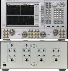
13 PNA Series 13

14 PNA Series Innovative Applications 14


15 PNA Series Innovative Applications Simple, fast, and accurate Pulsed-RF measurements 15

16 Pulsed-RF measurements 16

17 Pulsed-RF measurements 17


18 PNA Series Innovative Applications Fast, accurate Gain Compression versus frequency measurements of amplifiers and converters 18


19 PNA Series Innovative Applications Fast and accurate noise figure measurements 19


20 PNA Series Innovative Applications Accurate characterization of Mixers and Converters 20


21 PNA Series Innovative Applications Measuring Converters with Embedded LOs 21
 S-parameters Pout, Gain compression AM to PM conversion Gain compression vs.")
22 A G I L E N T P N A S E R I E S S Y S T E M D Y N A M I C R A N G E (EX A M P L E S W I T H N A G H Z 4 - P O R T P N A ) S-parameters Pout, Gain compression AM to PM conversion Gain compression vs. frequency Pulsed-RF measurements with internal pulse gen/mod. Page 22
 Conversion gain, Delay (SMC) Gain compression vs.")
23 A G I L E N T P N A S E R I E S S Y S T E M D Y N A M I C R A N G E (EX A M P L E S W I T H N A G H Z 4 - P O R T P N A ) Conversion gain, Delay (SMC) Gain compression vs. frequency RF, IF & LO match RF to IF, LO to RF/IF leak Page 23
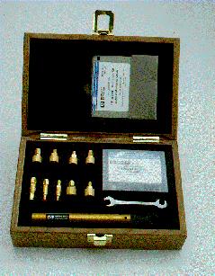
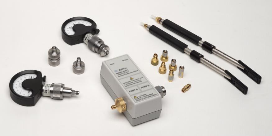
24 Advanced calibration tools 24


25 PNA Series Innovative Applications Extending the PNA to Millimeter-wave Frequencies Two- and four-port banded solutions Terahertz solutions without a test set Two- and four-port broadband, singlesweep solutions (10 MHz to 110 GHz) 25

26 Four-port system architecture 26

27 PNA-X Based 110 GHz Block Diagram 27

28 Broadband Amplifier Single Sweep Solution 10 MHz to 110 GHz calibrated S-parameters Accurate source power from 10 MHz to 110 GHz Gain compression with 48 db power sweep range at 98 GHz Output spectrum with 77 GHz input signal 28


29 PNA Series Innovative Applications Millimeter-wave applications Pulse profile at 77 GHz using the internal pulsed source and IF gates of the PNA. Example gain compression measurement of a 75 to 110 GHz packaged PHEMT transistor amplifier. 29


30 APPLICATIONS Gain Compression Mixer Measurement Pulse Measurement Differential Measurements Antenna Materials Measurements On wafer measurements Input Power vs. Freq Input Match vs. Freq Conversion Loss vs. Freq 30

31 Mixer Measurements Page 31 31


32 Fundamental Mixer Measurement IF Output 1 GHz RF Input GHz DUT LO Input GHz 32
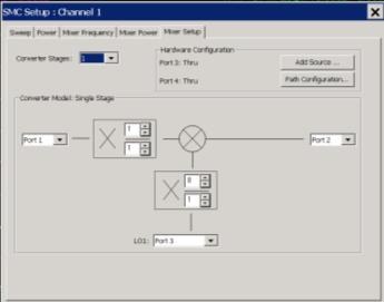
33 Harmonic Mixer Measurements NOTE: For Harmonic Mixer Measurements a two or 4 port Millimeter wave controller may be used In addition and external source or the second source of the PNA-X may be used for the LO IF Output 12.5 GHz GHz RF Input GHz DUT Harmonic Mixer. IF = 1/6 * RF LO= 1/8 * RF LO Input 9.35 GHz GHz 33

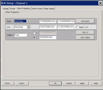
34 Harmonic Mixer Measurement IF OUT 99 MHz LO IN 9-13 GHz RF IN GHz DUT 34

35 Upconverter Example LO INPUT 9-13 GHz RF IN 1 GHz RF OUT GHz 35
36 Output Power Amplifier S Parameters & Compression Measurements Input Power 36
37 Compression: Setup 37

38 Compression: Measurement Calibrate S-Parameters Source Power Receiver power Stimulus Sweep source power Measure S-Parameters Absolute power Compression S-Parameters vs. Freq Power & Compression vs. Power in 38

39 Gain Compression Calibrate S-Parameters Source Power Receiver power Stimulus Sweep source power Measure S-Parameters Absolute power Compression 39
40 Differential Measurements 40

41 True-mode differential measurements 41

42 Differential Amplifier Measurement 42
 Port Sigma Port Gain: \"Delta in\" to \"Common-mode out\" Gain: \"Sigma")

43 Differential: Measurement Test Device: Magic Tee Delta Port (+) Port (-) Port Sigma Port Gain: "Delta in" to "Common-mode out" Gain: "Sigma in" to "Common-mode out" Sigma (+) Delta (-) Sigma (+) Delta (-) Gain: "Delta in" to "Differential out" Gain: "Sigma in" to "Differential out" 43
44 Pulse Measurements Page 44 44

45 Pulse: Setup 45
46 Pulse: Techniques 46

47 Pulse: Measurement Calibrate S-Parameters Source Power Receiver power Stimulus Pulse generation RF Pulse modulation Swept frequency or power Measure S-Parameters Absolute power Pulse waveform 100us pulse power waveform at 98GHz Page 47 47
48 Antenna Measurements 48
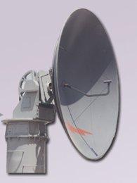
49 Antenna: Setup for local 49
50 Antenna: Setup for remote PNA-X N5261A 50
51 Antenna: Measurement Calibrate 1-port S-parameters Transmission Stimulus Sweep antenna position Measure Antenna match Antenna pattern 51

52 On-Wafer Measurements 52

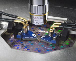
53 WinCal XE Automated 4-Port 53

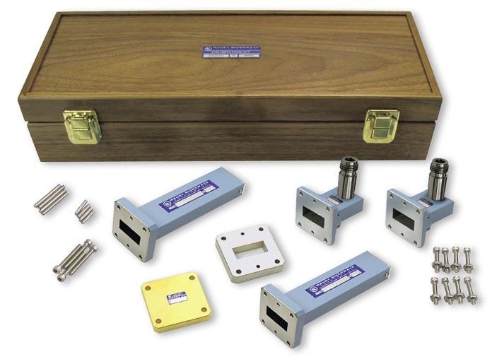
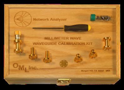
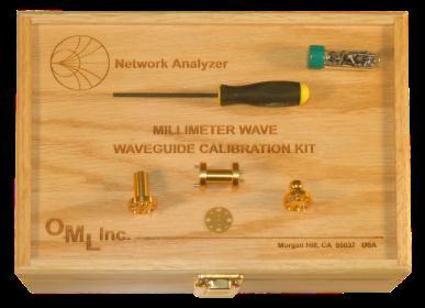
54 Waveguide Calibration 54
55 1-Port: Waveguide Calibration Methods Short -> Offset-Short -> Load (SOSL) Short -> Offset-Short -> Load -> Offset-load (SOSOL) 2-Port: Thru -> Reflect -> Line (TRL) Thru -> Reflect -> Match (TRM) Line -> Reflect -> Line (LRL) Easy to Implement Often Recommended Short -> Offset-short -> Load -> Thru (SOSLT) Short -> Offset-short -> Load -> Offset-load -> Thru (SOSOLT) 55
56 LRL Cal Standards Characteristics Reflect: reflection coefficient magnitude need not be known must be the same on each port reflection coefficient must be known within 1/4 wavelength LINE 1: S12 and S21 defined same as Line 2 S11 and S22 defined to be zero LINE 2: Z0 of the line establishes reference impedance, = LINE 1 insertion phase must not be equal to that of the Thru LINE Usable bandwidth for a single LINE 1/LINE 2 pair is <8:1 Bandwidth limited i.e. (stop freq)/(start freq) <8 S21 of line need not be known, BUT must have similar propagation properties as LINE 1 56
57 Assumptions The test ports have ideal aperture geometry. That they are perfectly aligned to the device-under-test (DUT). In the presence of waveguide aperture irregularities and misalignment, the validity of these assumptions breaks down as frequency increases. The source match of both lines are considered to be the same. For Calibration > 110 GHz LRL is the Calibration method is the best. 57
58 The Issue Reduced sizes D 2 D 3 D 6 D 5 D 4 D 1 WR-10 Waveguide Flange GHz W= 2.54mm H= 1.27mm R= 0.043mm max WR-05 Waveguide Flange GHz W=1.3mm H=0.648mm R= 0.043mm max ¼-offset shim = mm (10.391ps) Null shim = mm (8.492ps) ¼-offset shim = mm (9.704ps Null shim = mm (8.484ps) 58


 Rounded")

59 The Issue - Common Waveguide Irregulaties Oversized apertures (typ μm) Rounded corners & sidewalls Flange poor edge & surface finish Burrs 59
60 LRL Cal Standards Characteristics Reflect: reflection coefficient magnitude need not be known must be the same on each port reflection coefficient must be known within 1/4 wavelength LINE 1: S12 and S21 defined same as Line 2 S11 and S22 defined to be zero LINE 2: Z0 of the line establishes reference impedance, = LINE 1 insertion phase must not be equal to that of the Thru LINE Usable bandwidth for a single LINE 1/LINE 2 pair is <8:1 Bandwidth limited i.e. (stop freq)/(start freq) <8 S21 of line need not be known, BUT must have similar propagation properties as LINE 1 60

61 Electrical Evaluation Model for Validation 1 st order model of the WR5 and WR3 precision sections: Air block:- a x b = mm x mm for WR5 a x b = mm x mm for WR3 Wave Port excitations Length = 25.4mm for WR5 Length = mm for WR3 Gold block Conductivity=4.1e+7 S/m Assumed perfectly smooth 61
62 62


63 Fully Calibrated with Excellent Stability Cal Kit WR GHz < 0.1 db drift over 16 Hrs Includes bot 1/8 and ¼ wave shims Precision sections Precision Loads Shorts Supports: TRL calibration Offset Short Calibrations using Agilent s proprietary Weighted least squares methods. Offset Load Calibration using Agilent s Loss term compensation. Enhanced offset Calibration using multiple lines. 63
Agilent Technologies Gli analizzatori di reti della serie-x
 Agilent Technologies Gli analizzatori di reti della serie-x Luigi Fratini 1 Introducing the PNA-X Performance Network Analyzer For Active Device Test 500 GHz & beyond! 325 GHz 110 GHz 67 GHz 50 GHz 43.5
Platform Migration 8510 to PNA. Graham Payne Application Engineer Agilent Technologies
 Platform Migration 8510 to PNA Graham Payne Application Engineer Agilent Technologies We set the standard... 8410 8510 When we introduced the 8510, we changed the way S-parameter measurements were made!
Calibration and Accuracy in Millimeter Systems. Keith Anderson
 IMS2011 in Baltimore: A Perfect Match Calibration and Accuracy in Millimeter Systems Keith Anderson Agilent Technologies Copyright 2010 Agilent Technologies, Inc. Agenda Interfaces S-parameter calibration
Configuration of PNA-X, NVNA and X parameters
 Configuration of PNA-X, NVNA and X parameters VNA 1. S-Parameter Measurements 2. Harmonic Measurements NVNA 3. X-Parameter Measurements Introducing the PNA-X 50 GHz 43.5 GHz 26.5 GHz 13.5 GHz PNA-X Agilent
Agilent PNA and PNA-L Series Microwave Network Analyzers. The standard in microwave network analysis
 Agilent PNA and PNA-L Series Microwave Network Analyzers The standard in microwave network analysis PNA Family Sets the Standard for Microwave Network Analysis Choose the leader The PNA family builds on
A True Differential Millimeter Wave System with Port Power Control. Presented by: Suren Singh
 A True Differential Millimeter Wave System with Port Power Control Presented by: Suren Singh Agenda Need for True Differential and RF Power Control Vector Network Analyzer RF Port Power Control Port Power
Compact Series: S5065 & S5085 Vector Network Analyzers KEY FEATURES
 Compact Series: S5065 & S5085 Vector Network Analyzers KEY FEATURES Frequency range: 9 khz - 6.5 or 8.5 GHz Measured parameters: S11, S12, S21, S22 Wide output power adjustment range: -50 dbm to +5 dbm
PNA Family Microwave Network Analyzers (N522x/3x/4xB) CONFIGURATION GUIDE
 CONFIGURATION GUIDE") PNA Family Microwave Network Analyzers (N522x/3x/4xB) CONFIGURATION GUIDE Table of Contents PNA Family Network Analyzer Configurations... 05 Test set and power configuration options...05 Hardware options...
PNA Family Microwave Network Analyzers (N522x/3x/4xB) CONFIGURATION GUIDE Table of Contents PNA Family Network Analyzer Configurations... 05 Test set and power configuration options...05 Hardware options...
Network Analysis Basics
 Adolfo Del Solar Application Engineer adolfo_del-solar@agilent.com MD1010 Network B2B Agenda Overview What Measurements do we make? Network Analyzer Hardware Error Models and Calibration Example Measurements
Keysight Technologies PNA-X Series Microwave Network Analyzers
 Keysight Technologies PNA-X Series Microwave Network Analyzers Active-Device Characterization in Pulsed Operation Using the PNA-X Application Note Introduction Vector network analyzers (VNA) are the common
5 ESSENTIAL HINTS TO IMPROVE Millimeter-wave Network Analysis
 5 ESSENTIAL HINTS TO IMPROVE Millimeter-wave Network Analysis Contents 5 Essential Hints to Improve Millimeter-wave Network Analysis Ensure Accurate, Repeatable Results Go to Hint 1 > Calibrate for Better
Keysight Technologies PNA Microwave Network Analyzers
 Keysight Technologies PNA Microwave Network Analyzers Application Note Banded Millimeter-Wave Measurements with the PNA 02 Keysight PNA Microwave Network Analyzers Application Note Table of Contents Introduction...
Keysight Technologies PNA and PNA-L Series Microwave Network Analyzers
 Ihr Spezialist für Mess- und Prüfgeräte Keysight Technologies PNA and PNA-L Series Microwave Network Analyzers The standard in microwave network analysis datatec Ferdinand-Lassalle-Str. 52 72770 Reutlingen
Keysight Technologies PNA Microwave Network Analyzers The standard in microwave network analysis
 Keysight Technologies PNA Microwave Network Analyzers The standard in microwave network analysis Welcome to the world of PNAs The most popular microwave network analyzers The PNA family builds on Keysight
Pulsed VNA Measurements:
 Pulsed VNA Measurements: The Need to Null! January 21, 2004 presented by: Loren Betts Copyright 2004 Agilent Technologies, Inc. Agenda Pulsed RF Devices Pulsed Signal Domains VNA Spectral Nulling Measurement
RF and Microwave Test and Design Roadshow 5 Locations across Australia and New Zealand
 RF and Microwave Test and Design Roadshow 5 Locations across Australia and New Zealand Advanced VNA Measurements Agenda Overview of the PXIe-5632 Architecture SW Experience Overview of VNA Calibration
Vector Network Analyzer
 Vector Network Analyzer VNA Basics VNA Roadshow Budapest 17/05/2016 Content Why Users Need VNAs VNA Terminology System Architecture Key Components Basic Measurements Calibration Methods Accuracy and Uncertainty
Agilent PNA-X Series Microwave Network Analyzers
 Agilent PNA-X Series Microwave Network Analyzers Reach for unrivaled excellence 1 Choose the leader in network analysis Industry s Most Advanced RF Test Solution Reach for unrivaled excellence The PNA-X
PLANAR 814/1. Vector Network Analyzer
 PLANAR 814/1 Vector Network Analyzer Frequency range: 100 khz 8 GHz Measured parameters: S11, S12, S21, S22 Wide output power range: -60 dbm to +10 dbm >150 db dynamic range (1 Hz IF bandwidth) Direct
Advanced Test Equipment Rentals ATEC (2832)
") Established 1981 Advanced Test Equipment Rentals www.atecorp.com 800-404-ATEC (2832) Agilent 2-Port and 4-Port PNA-X Network Analyzer N5249A - 10 MHz to 8.5 GHz N5241A - 10 MHz to 13.5 GHz N5242A - 10
Established 1981 Advanced Test Equipment Rentals www.atecorp.com 800-404-ATEC (2832) Agilent 2-Port and 4-Port PNA-X Network Analyzer N5249A - 10 MHz to 8.5 GHz N5241A - 10 MHz to 13.5 GHz N5242A - 10
How do I optimize desired Amplifier Specifications?
 How do I optimize desired Amplifier Specifications? PAE (accuracy
THz Vector Network Analyzer Development & Measurements
 THz Vector Network Analyzer Development & Measurements Jeffrey L Hesler, Yiwei Duan, Brian Foley and Thomas Crowe Virginia Diodes Inc., Charlottesville, VA, USA Abstract: Virginia Diodes has been developing
Agilent Millimeter-Wave Network Analyzers 10 MHz to 110 GHz, with Extensions to 1.1 THz. Technical Overview
 Agilent Millimeter-Wave Network Analyzers 10 MHz to 110 GHz, with Extensions to 1.1 THz Technical Overview Single Sweep 10 MHz to 110 GHz Measurement Solutions Currently there are two solutions that offer
AV3672 Series Vector Network Analyzer
 AV3672 Series Vector Network Analyzer AV3672A/B/C/D/E (10MHz 13.5 GHz/26.5 GHz/43.5 GHz/50 GHz/67 GHz) Product Overview: AV3672 series vector network analyzer include AV3672A (10MHz 13.5GHz), AV3672B (10MHz
PLANAR S5048 and TR5048
 PLANAR S5048 and TR5048 Vector Network Analyzers KEY FEATURES Frequency range: 20 khz 4.8 GHz COM/DCOM compatible for LabView Measured parameters: and automation programming S11, S12, S21, S22 (S5048)
TEST & MEASURING INSTRUMENTS. Analyzer. (4 Ports) 4 Ports
 4 Ports") TEST & MEASURING INSTRUMENTS Analyzer (4 Ports) 4 Ports Key Features Frequrncy Range : 100kHz ~ 8GHz, 16 Parameters support (S11 ~ S44) Measurement time per point : 100us per point Wide Output Power Range
TEST & MEASURING INSTRUMENTS Analyzer (4 Ports) 4 Ports Key Features Frequrncy Range : 100kHz ~ 8GHz, 16 Parameters support (S11 ~ S44) Measurement time per point : 100us per point Wide Output Power Range
Compact Series: S5048 & TR5048 Vector Network Analyzers KEY FEATURES
 Compact Series: S5048 & TR5048 Vector Network Analyzers KEY FEATURES Frequency range: 20 khz - 4.8 GHz Measured parameters: S11, S12, S21, S22 (S5048) S11, S21 (TR5048) Wide output power adjustment range:
Agilent Millimeter-Wave Network Analyzers 10 MHz to 110 GHz, with Extensions to 1.1 THz. Technical Overview
 Agilent Millimeter-Wave Network Analyzers 10 MHz to 110 GHz, with Extensions to 1.1 THz Technical Overview Single Sweep 10 MHz to 110 GHz Measurement Solution Agilent currently offers the N5251A single
IMD Measurement Wizard for the E5072A ENA Series Network Analyzer Operation Manual. Agilent Technologies June 2012
 IMD Measurement Wizard for the E5072A ENA Series Network Analyzer Operation Manual Agilent Technologies June 2012 1 Important Notice Notices The information contained in this document is subject to change
Lightning D Vector Network Analyzers. Network Analysis Solutions for Design and Manufacturing. 40 MHz to 65 GHz
 Lightning 37000D Vector Network Analyzers 40 MHz to 65 GHz Network Analysis Solutions for Design and Manufacturing Vector Network Analyzers that offer... The 37000D Lightning Vector Network Analyzers are
EXTEND YOUR REACH GHz 60-90GHz GHz
 EXTEND YOUR REACH 50-75 GHz 60-90GHz 75-110 GHz Extend Your Reach Farran Technology and Copper Mountain Technologies, globally recognized innovators, with a combined 50 years experience in RF test and
Keysight 2-Port and 4-Port PNA-X Network Analyzer
 Keysight 2-Port and 4-Port PNA-X Network Analyzer N5249A - 0 MHz to 8.5 GHz N524A - 0 MHz to 3.5 GHz N5242A - 0 MHz to 26.5 GHz Data Sheet and Technical Specifications Documentation Warranty THE MATERIAL
Agilent PNA Microwave Network Analyzers
 Agilent PNA Microwave Network Analyzers Application Note 1408-3 Improving Measurement and Calibration Accuracy using the Frequency Converter Application Table of Contents Introduction................................................................2
Agilent PNA Microwave Network Analyzers
 Agilent PNA Microwave Network Analyzers Application Note 1408-15 Banded Millimeter-Wave Measurements with the PNA Table of Contents Introduction...3 System Configuration...4 System Operation...8 Configuring
Banded Milimeter Wave Network Analysis TECHNICAL OVERVIEW
 Banded Milimeter Wave Network Analysis TECHNICAL OVERVIEW Banded Measurement Solutions to 1.5 THz Keysight offers a variety of banded millimeter-wave solutions that enable the PNA/ PNA-X network analyzers
R&S ZVA-Zxx Millimeter-Wave Converters Network analysis up to 500 GHz
 ZVA-Zxx_bro_en_5214-2033-12.indd 1 Product Brochure 06.02 Test & Measurement R&S ZVA-Zxx Millimeter-Wave Converters Network analysis up to 500 GHz 28.10.2014 21:05:04 R&S ZVA-Zxx Millimeter-Wave Converters
Keysight Technologies Pulsed Antenna Measurements Using PNA Network Analyzers
 Keysight Technologies Pulsed Antenna Measurements Using PNA Network Analyzers White Paper Abstract This paper presents advances in the instrumentation techniques that can be used for the measurement and
Agilent N5250A PNA Millimeter-Wave Network Analyzer 10 MHz to 110 GHz
 Agilent N5250A PNA Millimeter-Wave Network Analyzer 10 MHz to 110 GHz Technical Overview High Performance Bench-Top Network Analyzer Maximize your frequency coverage with a single sweep from 10 MHz to
Impedance 50 (75 connectors via adapters)
") VECTOR NETWORK ANALYZER PLANAR 304/1 DATA SHEET Frequency range: 300 khz to 3.2 GHz Measured parameters: S11, S21, S12, S22 Dynamic range of transmission measurement magnitude: 135 db Measurement time
VECTOR NETWORK ANALYZER PLANAR 304/1 DATA SHEET Frequency range: 300 khz to 3.2 GHz Measured parameters: S11, S21, S12, S22 Dynamic range of transmission measurement magnitude: 135 db Measurement time
Confidence. on the Cutting Edge. Vector Network Analyzer Portfolio Brochure. In the Lab On the Manufacturing Floor In the Field. Anritsu Since 1895
 Anritsu Since 1895 Vector Network Analyzer Portfolio Brochure Confidence on the Cutting Edge In the Lab On the Manufacturing Floor In the Field For every measurement scenario from on-wafer device characterization
PLANAR 804/1. Vector Network Analyzer
 PLANAR 804/1 Vector Network Analyzer Frequency range: 100 khz 8 GHz Measured parameters: S11, S12, S21, S22 Wide output power range: -60 dbm to +10 dbm >145 db dynamic range (1 Hz IF bandwidth) Time domain
Agilent 2-Port and 4-Port PNA-X Network Analyzer. N5241A - 10 MHz to 13.5 GHz N5242A - 10 MHz to 26.5 GHz Data Sheet and Technical Specifications
 Agilent 2-Port and 4-Port PNA-X Network Analyzer N5241A - 10 MHz to 13.5 GHz N5242A - 10 MHz to 26.5 GHz Data Sheet and Technical Specifications Documentation Warranty THE MATERIAL CONTAINED IN THIS DOCUMENT
S3602A/B Vector Network Analyzer Datasheet
 S3602A/B Vector Network Analyzer Datasheet Saluki Technology Inc. The document applies to the vector network analyzers of the following models: S3602A vector network analyzer (10MHz-13.5GHz). S3602B vector
Agilent Network Analyzer Selection Guide
 Agilent Network Analyzer Selection Guide Please note: This document does not contain Agilent s most up-to-date network analyzer portfolio. This document is available for reference only for customers using
Agilent PNA-X Series Microwave Network Analyzers. Complete linear and nonlinear component characterization in a single instrument
 Agilent PNA-X Series Microwave Network Analyzers Complete linear and nonlinear component characterization in a single instrument Choose the leader in network analysis Industry s Most Advanced RF Test Solution
Experiment 12 - Measuring X-Parameters Using Nonlinear Vector Netowrk Analyzer
 ECE 451 Automated Microwave Measurements Laboratory Experiment 12 - Measuring X-Parameters Using Nonlinear Vector Netowrk Analyzer 1 Introduction In this experiment, rstly, we will be measuring X-parameters
Keysight Technologies PNA Family Microwave Network Analyzers
 Keysight Technologies PN Family Microwave Network nalyzers (N522x/3x/4x) Configuration Guide The -models of the PN family (N522x/3x/4x) will be discontinued June 2019. Their -model replacements are available
Agilent PNA Family Microwave Network Analyzers
 gilent PN Family Microwave Network nalyzers Configuration Guide This configuration guide describes standard configurations, options, accessories, upgrade kits and compatible peripherals for the PN Family
Measurements with Scattering Parameter By Joseph L. Cahak Copyright 2013 Sunshine Design Engineering Services
 Measurements with Scattering Parameter By Joseph L. Cahak Copyright 2013 Sunshine Design Engineering Services Network Analyzer Measurements In many RF and Microwave measurements the S-Parameters are typically
High Performance, Broadband Network Analysis Solutions
 Advanced Test Equipment Rentals E stablished 1981 www.atecorp.com 800-404-ATEC (2832) Technical Data Sheet & Configuration Guide High Performance, Broadband Network Analysis Solutions ME7838A Series Vector
X-Parameters with Active and Hybrid Active Load Pull
 X-Parameters with Active and Hybrid Active Load Pull Gary Simpson, CTO Maury Microwave EuMW 2012 www.maurymw.com 1 General Load Pull Overview 2 Outline 1. Introduction to Maury Microwave 2. Basics and
Limitations And Accuracies Of Time And Frequency Domain Analysis Of Physical Layer Devices
 Limitations And Accuracies Of Time And Frequency Domain Analysis Of Physical Layer Devices Outline Short Overview Fundamental Differences between TDR & Instruments Calibration & Normalization Measurement
Abstract: Stringent system specifications impose tough performance requirements on the RF and microwave cables used in aerospace and defense
 1 Abstract: Stringent system specifications impose tough performance requirements on the RF and microwave cables used in aerospace and defense communication systems. With typical tools, it can be very
Microwave Network Analyzers PNA-X Series BROCHURE
 Microwave Network Analyzers PNA-X Series BROCHURE Industry s Most Advanced RF Test Solution Reach for unrivaled excellence Choose the leader in network analysis The PNA-X Series of microwave network analyzers
Antenna Measurement using Vector Network Analyzer. Jong-hwan Keum Agilent Technologies
 Antenna Measurement using Vector Network Analyzer Jong-hwan Keum Agilent Technologies Agenda Overview Antenna Measurement System Configuration(Examples) Antenna Measurement System Design Considerations
Agilent Network Analyzer Selection Guide
 Agilent Network Analyzer Selection Guide Network Analyzers to Meet Your Needs Agilent offers a variety of network analyzers with the frequency, performance, and versatility to meet your measurement needs.
Keysight 2-Port and 4-Port PNA-X Network Analyzer
 Keysight 2-Port and 4-Port PNA-X Network Analyzer N5249A - 0 MHz to 8.5 GHz N524A - 0 MHz to 3.5 GHz N5242A - 0 MHz to 26.5 GHz Data Sheet and Technical Specifications Documentation Warranty THE MATERIAL
Comparison of Various RF Calibration Techniques in Production: Which is Right for You? Daniel Bock, Ph.D.
 Comparison of Various RF Calibration Techniques in Production: Which is Right for You? Daniel Bock, Ph.D. Overview Introduction How does Calibration Work Types of Calibrations Comparison of Calibration
Overcome mmwave Component Test Challenges. Senior Project Manager / Keysight Technologies
 Overcome mmwave Component Test Challenges Senior Project Manager / Keysight Technologies Kenny Liao 2018.06.11 Taipei D I S C U S S I O N T O P I C S Millimeter Wave Component Application Space Millimeter
Fast and Accurate Simultaneous Characterization of Signal Generator Source Match and Absolute Power Using X-Parameters.
 Fast and Accurate Simultaneous Characterization of Signal Generator Source Match and Absolute Power Using X-Parameters. April 15, 2015 Istanbul, Turkey R&D Principal Engineer, Component Test Division Keysight
Keysight Technologies Accurate Mixer Measurements Using the ENA RF Networks Analyzers Frequency-Offset Mode. Application Note
 Keysight Technologies Accurate Mixer Measurements Using the ENA RF Networks Analyzers Frequency-Offset Mode Application Note 1 Measurement Parameters of the Mixer The ENA FOM offers two advanced mixer
Optoelectronic Components Testing with a VNA(Vector Network Analyzer) VNA Roadshow Budapest 17/05/2016
 VNA Roadshow Budapest 17/05/2016") Optoelectronic Components Testing with a VNA(Vector Network Analyzer) VNA Roadshow Budapest 17/05/2016 Content Introduction Photonics & Optoelectronics components Optical Measurements VNA (Vector Network
Optoelectronic Components Testing with a VNA(Vector Network Analyzer) VNA Roadshow Budapest 17/05/2016 Content Introduction Photonics & Optoelectronics components Optical Measurements VNA (Vector Network
S3602C Vector Network Analyzer Datasheet
 S3602C Vector Network Analyzer Datasheet Saluki Technology Inc. The document applies to the vector network analyzers of the following models: S3602C vector network analyzer (10MHz - 43.5GHz). Options of
Measurements 2: Network Analysis
 Measurements 2: Network Analysis Fritz Caspers CAS, Aarhus, June 2010 Contents Scalar network analysis Vector network analysis Early concepts Modern instrumentation Calibration methods Time domain (synthetic
Vector Network Analysis
 Portfolio Brochure Vector Network Analysis Product Portfolio Vector Network Analysis VNA Innovation Timeline In 1965, Anritsu filed the patent that defined the first modern Vector Network Analyzer (VNA).
Microwave & RF Device Characterization Solutions
 Microwave & RF Device Characterization Solutions MT2000 Mixed-Signal Active Load Pull System (1.0 MHz to 40.0 GHz) And MT2001 System Software From Powered by Maury Microwave is ISO: 9001:2008/AS9100C Certified.
Keysight Technologies PNA and PNA-L Series Microwave Network Analyzers
 Ihr Spezialist für Mess- und Prüfgeräte Keysight Technologies PNA and PNA-L Series Microwave Network Analyzers The standard in microwave network analysis PNA Family Sets the Standard for Microwave Network
Narrow Pulse Measurements on Vector Network Analyzers
 Narrow Pulse Measurements on Vector Network Analyzers Bert Schluper Nearfield Systems Inc. Torrance, CA, USA bschluper@nearfield.com Abstract - This paper investigates practical aspects of measuring antennas
Keysight Technologies FieldFox Handheld Analyzers
 Keysight Technologies FieldFox Handheld Analyzers 4/6.5/9/14/18/26.5/32/44/50 GHz Data Sheet N9913A N9914A N9915A N9925A N9935A N9916A N9926A N9936A N9917A N9927A N9937A N9918A N9928A N9938A N9950A N9951A
Introduction to On-Wafer Characterization at Microwave Frequencies
 Introduction to On-Wafer Characterization at Microwave Frequencies Chinh Doan Graduate Student University of California, Berkeley Introduction to On-Wafer Characterization at Microwave Frequencies Dr.
Keysight Technologies FieldFox Handheld Analyzers
 Keysight Technologies FieldFox Handheld Analyzers 4/6.5/9/14/18/26.5/32/44/50 GHz Data Sheet N9913A N9914A N9915A N9925A N9935A N9916A N9926A N9936A N9917A N9927A N9937A N9918A N9928A N9938A N9950A N9951A
Overcoming Mixer Measurement Challenges
 Overcoming Mixer Measurement Challenges October 10, 2002 presented by: Robb Myer Dave Ballo Today we will be looking at overcoming measurements challenges associated with frequency translating devices
Gain Lab. Image interference during downconversion. Images in Downconversion. Course ECE 684: Microwave Metrology. Lecture Gain and TRL labs
 Gain Lab Department of Electrical and Computer Engineering University of Massachusetts, Amherst Course ECE 684: Microwave Metrology Lecture Gain and TRL labs In lab we will be constructing a downconverter.
9 khz to 4.5/6.5/8.5 GHz 100 khz to 4.5/6.5/8.5 GHz (with bias tees) 300 khz to 14/20 GHz (with bias tees)
 300 khz to 14/20 GHz (with bias tees)") Agilent E5071C ENA Network Analyzer 9 khz to 4.5/6.5/8.5 GHz 100 khz to 4.5/6.5/8.5 GHz () 300 khz to 14/20 GHz () The industry standard in RF network analysis ENA New Standards in Speed, Accuracy and
Agilent E5071C ENA Network Analyzer 9 khz to 4.5/6.5/8.5 GHz 100 khz to 4.5/6.5/8.5 GHz () 300 khz to 14/20 GHz () The industry standard in RF network analysis ENA New Standards in Speed, Accuracy and
TEST EQUIPMENT PLUS. Signal Hound USB-SA44B / USB-TG44A. Application Note 1: The Smith Chart. Rev. 0
 Rev. 0 TEST EQUIPMENT PLUS Signal Hound USB-SA44B / USB-TG44A Application Note 1: The Smith Chart USING THE SMITH CHART Chapter 1 1 Using the Smith Chart Making Single-Frequency Vector Impedance Measurements
Agilent AN Applying Error Correction to Network Analyzer Measurements
 Agilent AN 287-3 Applying Error Correction to Network Analyzer Measurements Application Note 2 3 4 4 5 6 7 8 0 2 2 3 3 4 Table of Contents Introduction Sources and Types of Errors Types of Error Correction
Keysight Technologies Network Analyzer Measurements: Filter and Amplifier Examples. Application Note
 Keysight Technologies Network Analyzer Measurements: Filter and Amplifier Examples Application Note Introduction Both the magnitude and phase behavior of a component are critical to the performance of
Keysight Technologies Amplifier and CW Swept Intermodulation - Distortion Measurements using the PNA Microwave Network Analyzers.
 Keysight Technologies Amplifier and CW Swept Intermodulation - Distortion Measurements using the PNA Microwave Network Analyzers Application Note Introduction This application note covers testing of an
Keysight Technologies FieldFox Handheld Analyzers
 Keysight Technologies FieldFox Handheld Analyzers 4/6.5/9/14/18/26.5/32/44/50 GHz Data Sheet N9913A N9914A N9915A N9925A N9935A N9916A N9926A N9936A N9917A N9927A N9937A N9918A N9928A N9938A N9950A N9951A
Keysight N4373E 43.5/50/67 GHz Single-Mode Fiber Lightwave Component Analyzer for 100G/400G/1T Electro-Optical Test
 DATA SHEET Keysight N4373E 43.5/50/67 GHz Single-Mode Fiber Lightwave Component Analyzer for 100G/400G/1T Electro-Optical Test General Information The performance of digital, photonic transmission is ultimately
New Ultra-Fast Noise Parameter System... Opening A New Realm of Possibilities in Noise Characterization
 New Ultra-Fast Noise Parameter System... Opening A New Realm of Possibilities in Noise Characterization David Ballo Application Development Engineer Agilent Technologies Gary Simpson Chief Technology Officer
Keysight Technologies E5071C ENA Vector Network Analyzer. E5092A Configurable Multiport Test Set
 Keysight Technologies E5071C ENA Vector Network Analyzer 9 khz to 4.5/6.5/8.5 GHz 100 khz to 4.5/6.5/8.5 GHz (with bias tees) 300 khz to 14/20 GHz (with bias tees) E5092A Configurable Multiport Test Set
What s inside. Highlights. Welcome. Mixer test third in a series. New time-domain technique for measuring mixer group delay
 What s inside 2 New time-domain technique for measuring mixer group delay 3 Uncertainty in mixer group-delay measurements 5 Isolation a problem? Here s how to measure mixer group delay 6 Low-power mixer
Load Pull with X-Parameters A New Paradigm for Modeling and Design
 Load Pull with X-Parameters A New Paradigm for Modeling and Design Gary Simpson, CTO Maury Microwave Anaheim, May 2010 For a more detailed version of this presentation, go to www.maurymw.com/presentation.htm
Keysight Technologies Making Accurate Intermodulation Distortion Measurements with the PNA-X Network Analyzer, 10 MHz to 26.5 GHz
 Keysight Technologies Making Accurate Intermodulation Distortion Measurements with the PNA-X Network Analyzer, 10 MHz to 26.5 GHz Application Note Overview This application note describes accuracy considerations
Keysight Technologies PNA Microwave Network Analyzers
 Keysight Technologies PNA Microwave Network Analyzers Mixer Conversion-Loss and Group-Delay Measurement Techniques and Comparisons Application Note Table of Contents Introduction... 2 Conversion Loss...
Agilent Antenna and RCS Measurement Configurations Using PNA Microwave Network Analyzers. White Paper
 Agilent Antenna and RCS Measurement Configurations Using PNA Microwave Network Analyzers White Paper Abstract As technology changes, new and different techniques for measuring and characterizing antenna
Introduction. Part 1. Introduction...2
 Keysight Technologies Simple Scalar Network Analysis of Frequency Converter Devices using the U2000 USB Power Sensor Series with the ENA Network Analyzer Application Note Introduction This application
A New Noise Parameter Measurement Method Results in More than 100x Speed Improvement and Enhanced Measurement Accuracy
 MAURY MICROWAVE CORPORATION March 2013 A New Noise Parameter Measurement Method Results in More than 100x Speed Improvement and Enhanced Measurement Accuracy Gary Simpson 1, David Ballo 2, Joel Dunsmore
Vector network analysis Calibration and advanced measurements
 Vector network analysis Calibration and advanced measurements Application examples (I) Production-line testing On-wafer testing Datum VNA training Titel R&S 2 Canada 2 Application examples (II) RCS measurement
Many devices, particularly
 From March 2003 High Frequency Electronics Copyright 2003, Summit Technical Media, LLC Techniques for Pulsed S-Parameter Measurements By David Vondran Anritsu Company Many devices, particularly power Pulsed
External Source Control
 External Source Control X-Series Signal Analyzers Option ESC DEMO GUIDE Introduction External source control for X-Series signal analyzers (Option ESC) allows the Keysight PXA, MXA, EXA, and CXA to control
Antenna and RCS Measurement Configurations Using Agilent s New PNA Network Analyzers
 Antenna and RCS Measurement Configurations Using Agilent s New PNA Network Analyzers John Swanstrom, Application Engineer, Agilent Technologies, Santa Rosa, CA Jim Puri, Applications Engineer, Agilent
772D coaxial dual-directional coupler 773D coaxial directional coupler. 775D coaxial dual-directional coupler 776D coaxial dual-directional coupler
 72 772D coaxial dual-directional coupler 773D coaxial directional coupler 775D coaxial dual-directional coupler 776D coaxial dual-directional coupler 777D coaxial dual-directional coupler 778D coaxial
MEASUREMENT OF LARGE SIGNAL DEVICE INPUT IMPEDANCE DURING LOAD PULL
 Model M956D CORPORAION MEASUREMEN OF LARGE SIGNAL DEVICE INPU IMPEDANCE DURING LOAD PULL Abstract Knowledge of device input impedance as a function of power level and load matching is useful to fully understand
Agilent 4-Port PNA-L Network Analyzers
 Agilent 4-Port PNA-L Network Analyzers N5230A Options 240, 245 300 khz to 20 GHz Speed and accuracy you can count on Integrated 4-port, balanced measurements up to 20 GHz Introducing the 4-port PNA-L network
CobaltFx Series EXTEND YOUR REACH. Frequency Extender System from. Frequency bands from: GHz, GHz, GHz
 CobaltFx Series TM Frequency Extender System from TM Frequency bands from: 50-75 GHz, 60-90 GHz, 75-110 GHz EXTEND YOUR REACH USA: +1.17..5400 61 E. New York St Indianapolis, IN 460 www.coppermountaintech.com
E-band and mmwave Components & Sub-Assemblies testing Challenges New Technology. VNA Roadshow Budapest 17/05/2016
 E-band and mmwave Components & Sub-Assemblies testing Challenges New Technology VNA Roadshow Budapest 17/05/2016 Agenda Applications drive the need Challenges faced by device characterization engineers
Keysight Technologies PNA-X Series Microwave Network Analyzers
 Keysight Technologies PNA-X Series Microwave Network Analyzers 02 Keysight PNA-X Series Microwave Network Analyzers - Brochure Industry s Most Advanced RF Test Solution Reach for unrivaled excellence Choose
PLANAR R54. Vector Reflectometer KEY FEATURES
 PLANAR R54 Vector Reflectometer KEY FEATURES Frequency range: 85 MHz 5.4 GHz Reflection coefficient magnitude and phase, cable loss, DTF Transmission coefficient magnitude when using two reflectometers