Ku-Band Receiver System for SHAO
|
|
|
- Daniel Peters
- 6 years ago
- Views:
Transcription

1 Ku-Band Receiver System for SHAO Overview Brent Willoughby July 2014 Atacama Large Millimeter/submillimeter Array Expanded Very Large Array Robert C. Byrd Green Bank Telescope Very Long Baseline Array
2 SHAO 65m Ku band system deliverables One complete -style Ku-band receiver One complete Feed matched to 65m optics One additional Ku-band Ortho-Mode Transducer with a rotary flange for testing purposes Upgraded software package One Scott Tee Cryo refrigerator AC supply Spare units of all critical receiver components C band upgrade components 2

3 SHAO Ku Band receiver and Feed Upgraded 5% and 50% CAL design Option for temperature controlled Noise Diodes Scott Tee delivery to enable full Cryo control 3

4 SHAO Ku Block Diagram 4
5 Compliance Matrix: System testing and verification Req. No. Abbreviated Description Compliance Method Additional Notes Compliance 2.1 -equivalent performance By design Receiver and feed match capabilities by utilizing proven design in hardware, software, and firmware as deployed in. Specific performance requirements are found below Interoperability By design & inspection Structural interfaces and integration verified via 3D model to the 65m antenna prior to shipment Receiver & feed integrate via C-band M/C and power distribution by virtual of identical design and lab usage Receiver integrates with SHAO IF switching and distribution systems by design. 5
6 2.3 Receiver Bandwidth 2.3 Receiver Bandwidth FAT GHz verified. See SHAO Ku Band 12-18Ghz Receiver System technical manual, section 9. 6
7 2.4.3 Receiver Noise Temperature Receiver Noise Temperature, averaged, at 15 K or lower with SHAO feed SAT, FAT SAT: Verify Trcvr on site at a single frequency within the GHz BW. FAT: In-lab measurements average 8.3 K, See SHAO Ku Band Ghz Receiver System technical manual, section 9.1. FAT SAT TBD 7
8 4.4.6 Cool Down from ambient Cool down from ambient temperature vs. time 15 K and 50 K SAT, FAT 12 hours cool down time. FAT: recorded cool down time <9 hours, as recorded in SHAO Ku Band 12-18Ghz Receiver System technical manual, Figure 5.5 SAT: To be measured at SHAO FAT SAT TBD 8
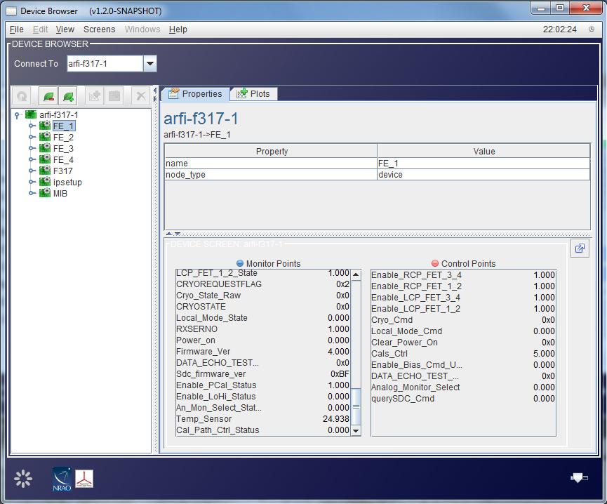
9 4.6.4 Monitor and Control Monitor and Control function verification SAT,FAT Verified at NRAO through utilization of automated test stands. See SHAO Ku Band 12-18Ghz Receiver System technical manual, section 9 for typical data produced. 9
10 Compliance Matrix: System testing and verification 2.5 RFI By design Hardware design utilizes the receiver design, and no specific RFI immunity is required. 2.6 Safety By design Built-in interlocks are designed into the receiver cryogenic system. 2.7 Maintenance & System Life By design & inspection There are no exposed VDC terminals above +33 Volts or any exposed VAC terminals. See SHAO Ku Band 12-18Ghz Receiver System technical manual, section based design operates in environment similar to SHAO environment. SHAO shall provide a weatherproof and temperature stable environment that is at least 20 C +/- 10 with a relative humidity of 20-80% Verified spare parts kit prior to shipping Recommended maintenance protocols should be followed for commercial Cryogenic components such as the CTI 350 refrigerator. 10
11 Noise Calibration High 50% Tsys High and Low Noise Calibration temperature (K ) FAT The noise calibration signal input is equivalent to ~5% (low noise) or ~50% (high noise) of the nominal Tsys, and is remotely selectable. Tsys is designed to be 27 K, see req , and measurements show appropriate values as recorded in SHAO Ku Band 12-18Ghz Receiver System technical manual, section 9. 11
12 Noise Calibration Low 5% Tsys 12
13 System Gain System Gain (db) FAT The Ku Receiver system Gain shall be nominally 50 db, taken using a 300K input termination and output power measured over the full bandwidth as recorded in SHAO Ku Band manual. NON- WAIVER GRANTED 13
14 Output power Axial ratio Output Power (dbm) FAT Output power shall be -35 dbm/channel nominal over full bandwidth with 77 K cold load over the feed. Averaged value is -32dBm, as shown in SHAO Ku Band 12-18Ghz Receiver System technical manual, section Receiver Axial Ratio (db) FAT <1.5 db with a goal of 1 db. See figure 9.3 in SHAO Ku Band 12-18Ghz Receiver System technical manual. 14
 15")
15 , Headroom 1% gain compression Headroom (db) FAT The estimated headroom of the Ku band receiver is greater than 28 db. Headroom is defined as the ratio of 1% compressed output power to the receiver output on cold sky (Tsys 27K) 15
 7 Total Power Stability (ASD) FAT As measured in the")
16 Total power (ASD) Total Power Stability (ASD) FAT As measured in the laboratory test, provided as characterization of receiver. 16

17 Calibration modes Calibration Modes Features & Interfaces By design Requirements cover the various features and interfaces provided by an style receiver. 17
18 Compliance Matrix: System testing and verification RCP & LCP RF output connector type By design Connector shall be SMA-F RCP and LCP highattenuation outputs By design, FAT RCP and LCP high-attenuation outputs provided from a coupler before the LNAs. Signal provided at -30dB. Connectors for this output shall also be SMA-F. Measured at -34dB NON- WAIVER GRANTED 18
19 DC Voltage tolerance Nominal receiver DC regulated voltage outputs: +/-15 VDC, +/- 5VDC, +28 VDC FAT +/- 5% tolerance Nominal values shown in SHAO Ku Band 12-18Ghz Receiver System technical manual, section

20 Nominal Receiver current Nominal Current for each regulated supply voltage FAT As measured in the laboratory test. Nominal values shown in SHAO Ku Band 12-18Ghz Receiver System technical manual, section TBD by NRAO 20
21 Compliance Matrix: System Testing and verification Receiver input voltage SAT -48VDC 10 Amperes shall be provided by SHAO TBD by SHAO Scott Tee AC input voltage SAT 220 Vac 50Hz shall be provided by SHAO TBD by SHAO Scott Tee AC output voltage By design 150 VAC dual phase to refrigerator, 120 VAC single phase for solenoid and heater 21
22 Compliance Matrix: System testing and verification Cool down from ambient plot of 15K and 50K temperature vs. time FAT 12 hours cool down time. Recorded cool down time <9 hours, as recorded in SHAO Ku Band 12-18Ghz Receiver System technical manual, Figure Dewar Leak Rate FAT 7.5*10-6 cm 3 /s He as measured by NRAO Overall leak rate measured at 3.8*10-6 cm 3/s He Cryogenic Design by NRAO By design The Ku-band receiver system will use a Model CTI 350 Refrigerator. The Ku-band receiver shall be cryogenically cooled using a closed-cycle refrigeration system, based on a 2-stage Gifford-McMahon refrigerator, with pressurized ultra-high purity helium gas as the refrigerant Cryogenic Hardware from SHAO SAT The 1st stage at 50 K shall provide cooling for the thermal radiation shield, and the 2nd stage at 15 K shall be used for cooling the LNAs and OMT assembly. SHAO will provide all components of the helium refrigerant system to operate the CTI 350. The He supply pressure shall nominally be 280 ±20PSI. The He return pressure shall nominally be 80 ±20PSI. TBD by SHAO 22
23 Compliance Matrix: System testing and verification Vacuum Design by NRAO By design The pressure in the manifold and Dewar assembly shall be monitored by individual thermocouple-type vacuum sensors provided by NRAO. A 0.75 in. (19mm) ID vacuum hose shall be used to connect the vacuum pump to the receiver vacuum manifold. The electronics within the receiver assembly/card cage shall perform the proper sequencing of pump, solenoid, heater, and refrigerator control, to allow automatic cooldown or warm-up via a single command, under direct manual or remote control. NRAO will provide a pump request electronic module which can interface to the SHAO-selected vacuum pump. The Scott Tee module will also provide the required 120 VAC for control powering the solenoid vacuum valve. The electronics within the receiver assembly/card cage will control the pump request module Vacuum Hardware from SHAO SAT SHAO will provide a vacuum pump with a blank-off pressure of < 10µm Hg, (0.0133mbar). SHAO will provide the vacuum lines up to the receiver vacuum manifold input. TBD by SHAO 23
24 Compliance Matrix: System Testing and verification PC-based laboratory program update By design Program shall be updated form C-band deliverable to include Ku-band system M&C system hardware By design The analog and digital I/O M&C system shall have a 50-pin D-sub interface connector. The Ku-band system shall include the card cage Complete set of monitor data collected at final receiver/feed test SAT As provided and shown during installation card cage design By design The card cage shall contain an LNA bias card ( ) and control card ( ) with capabilities as described in Systems Requirements document Diode protection card By design A diode protection card shall be used on the Ku-band receiver. This card is mounted inside the dewar directly to the 32-pin hermetic feed-thru connector. The diode protection card protects the LNAs from over-voltage conditions and transient spikes. It also contains an EPROM from which the M/C system can obtain the receiver s ID information (i.e., frequency band, serial number and revision number). TBD 24
25 Questions/comments? 25
5 RECEIVERS TABLE TBD: EVLA RECEIVER FREQUENCY RANGES AND OPERATING TEMPERATURES
 EVLA Project Book, Chapter 5. 5 RECEIVERS Robert Hayward, Ed Szpindor, and Daniel J. Mertely Last changed 2001-Oct-30 Revision History 2001-July-01: Initial release. 2001-Oct-01: Sys-def & detail added.
EVLA Receivers PDR. (4m, P,) L, S, C BAND RECEIVERS. AuthorDaniel (Mert) Mertely
 L, S, C BAND RECEIVERS. AuthorDaniel (Mert) Mertely") EVLA Receivers PDR (4m, P,) L, S, C BAND RECEIVERS Daniel (Mert) Mertely 1 Trx Projections EVLA RX FREQ RANGES AND OP TEMPS: REQUIRED vs. PROJECTED BND FRQ REQ CURNT CURNT CALC IDR RANGE Tsys (2) Tsys
EVLA Receivers PDR (4m, P,) L, S, C BAND RECEIVERS Daniel (Mert) Mertely 1 Trx Projections EVLA RX FREQ RANGES AND OP TEMPS: REQUIRED vs. PROJECTED BND FRQ REQ CURNT CURNT CALC IDR RANGE Tsys (2) Tsys
Cryogenic Systems and Receiver Maintenance
 Cryogenic Systems and Receiver Maintenance Christian Plötz Email: christian.ploetz@bkg.bund.de Federal Agency for Cartography and Geodesy Geodetic Observatory Wettzell Germany Objective Provide basic knowledge
AVN Training HartRAO 2016
 AVN Training HartRAO 2016 Microwave 1 Overview Introduction to basic components used in microwave receivers. Performance characteristics of these components. Assembly of components into a complete microwave
Noise Calibration Systems and Accessories DATA SHEET / 4N-062
 Noise Calibration Systems and Accessories DATA SHEET / 4N-062 // MARCH 2018 Noise Calibration Systems and Components MT7149J99 WR10 75 110 GHz Noise Calibration System Introduction The Maury Noise Calibration
EVLA Front-End CDR. EVLA Ka-Band (26-40 GHz) Receiver
 Receiver") EVLA Front-End CDR EVLA Ka-Band (26-40 GHz) Receiver 1 EVLA Ka-Band Receiver Overview 1) General Description 2) Block Diagram 3) Noise & Headroom Model 4) Feed & Thermal Gap 5) RF Tree - Phase-Shifter
EVLA Front-End CDR EVLA Ka-Band (26-40 GHz) Receiver 1 EVLA Ka-Band Receiver Overview 1) General Description 2) Block Diagram 3) Noise & Headroom Model 4) Feed & Thermal Gap 5) RF Tree - Phase-Shifter
EVLA Front-End CDR. Overview & System Requirements
 EVLA Front-End CDR Overview & System Requirements 1 Overview & System Requirements Introduction to the EVLA Front-End Task EVLA vs. VLA Feeds Receivers System Requirements, including: System Temperatures
Physical Properties Measurement System (PPMS): Detailed specifications: Basic unit cryogen- free
: Detailed specifications: Basic unit cryogen- free") Physical Properties Measurement System (PPMS): A Cryogen-free Physical Properties Measurement system that operates over a wider range of temperature and magnetic fields: fully automated/computer controlled
Physical Properties Measurement System (PPMS): A Cryogen-free Physical Properties Measurement system that operates over a wider range of temperature and magnetic fields: fully automated/computer controlled
Detector Systems. Graeme Carrad
 Detector Systems Graeme Carrad November 2011 The Basic Structure of a typical Radio Telescope Antenna Receiver Conversion Digitiser Signal Processing / Correlator They are much the same CSIRO. Radiotelescope
Figure 1 Photo of an Upgraded Low Band Receiver
 NATIONAL RADIO ASTRONOMY OBSERVATORY SOCORRO, NEW MEXICO EVLA TECHNICAL REPORT #175 LOW BAND RECEIVER PERFORMANCE SEPTMBER 27, 2013 S.DURAND, P.HARDEN Upgraded low band receivers, figure 1, were installed
NATIONAL RADIO ASTRONOMY OBSERVATORY CHARLOTTESVILLE, VIRGINIA. ELECTRONICS DIVISION INTERNAL REPORT No. 275 CRYOGENIC, HEMT, LOW-NOISE RECEIVERS
 NATIONAL RADIO ASTRONOMY OBSERVATORY CHARLOTTESVILLE, VIRGINIA ELECTRONICS DIVISION INTERNAL REPORT No. 275 CRYOGENIC, HEMT, LOW-NOISE RECEIVERS FOR 1.3 TO 43 GHz RANGE S. WEINREB M. W. POSPIESZALSKI R.
Table 5.1 Specifications for The Evaluation Receivers (33-45?) GHz HFET amplifier GHz SIS mixer GHz (HFET amp covers GHz)
 GHz HFET amplifier GHz SIS mixer GHz (HFET amp covers GHz)") MMA Project Book, Chapter 5 Section 1 Evaluation Receivers John Payne Graham Moorey Last changed 1999-May-2 Revision History: 1998-11-18: Major revision 1999-05-02: Minor specification changes in Table
MMA Project Book, Chapter 5 Section 1 Evaluation Receivers John Payne Graham Moorey Last changed 1999-May-2 Revision History: 1998-11-18: Major revision 1999-05-02: Minor specification changes in Table
Diseño del Criostato del Receptor de Banda Ancha
 Diseño del Criostato del Receptor de Banda Ancha José Manuel Serna, Beatriz Vaquero, Félix Tercero, Samuel López Informe Técnico IT-CDT 2015-18 [Los desarrollos descritos en este informe técnico han sido
Improved Power Efficiency for Cryogenics at the Very Large Array
 C19_001 1 Improved Power Efficiency for Cryogenics at the Very Large Array D. Urbain, W. Grammer, G. Peck, J. Jackson, S. Durand National Radio Astronomy Observatory Socorro, NM 87801 ABSTRACT The National
Atacama Large Millimeter/submillimeter Array Expanded Very Large Array Robert C. Byrd Green Bank Telescope Very Long Baseline Array
 Atacama Large Millimeter/submillimeter Array Expanded Very Large Array Robert C. Byrd Green Bank Telescope Very Long Baseline Array A Planar OMT for the 8-12 GHz Receiver Front-End Michael Stennes October
Engineering Expertise for Space Communications. Wideband Compact Cryogenic Receiver QRFH - SN: 01 - FAT. Test Report
 Engineering Expertise for Space Communications Reference: REP/1704/3591 Wideband Compact Cryogenic Receiver QRFH - SN: 01 - FAT Test Report Document Reference : REP/1704/3986 Date : 06 th December 2016
VGOS MEMO #042 MASSACHUSETTS INSTITUTE OF TECHNOLOGY HAYSTACK OBSERVATORY WESTFORD, MASSACHUSETTS August 22, 2016
 To: From: Subject: VGOS MEMO #042 MASSACHUSETTS INSTITUTE OF TECHNOLOGY HAYSTACK OBSERVATORY WESTFORD, MASSACHUSETTS 01886 Space Geodesy Project August 22, 2016 Ganesh Rajagopalan and Chris Eckert Failure
The Sardinia Radio Telescope conversion, distribution, and receiver control system
 Mem. S.A.It. Suppl. Vol. 10, 66 c SAIt 2006 Memorie della Supplementi The Sardinia Radio Telescope conversion, distribution, and receiver control system J. Monari, A. Orfei, A. Scalambra, S. Mariotti,
Valon Synthesizer RFI Test Report
 Page: Page 1 of 10 VEGAS-003-A-REP Version: A Prepared By: Name(s) and Signature(s) Organization Date C.Beaudet NRAO-GB 2011-11-29 J.Ray NRAO-GB 2013-03-18 Page: Page 2 of 10 Change Record Version Date
Block Upconverters for Integration in High Power Amplifiers
 R Back to Block/Fixed Tuned Converters Block Upconverters for Integration in High Power Amplifiers Block Upconverters For Integration In High Power Amplifiers C-, X- and Ku-Band Models (except UPBA-13)
A Noise-Temperature Measurement System Using a Cryogenic Attenuator
 TMO Progress Report 42-135 November 15, 1998 A Noise-Temperature Measurement System Using a Cryogenic Attenuator J. E. Fernandez 1 This article describes a method to obtain accurate and repeatable input
TECHNICAL SPECIFICATIONS OF STORES AND DRAWINGS.
 TECHNICAL SPECIFICATIONS OF STORES AND DRAWINGS. SECTION - C Technical Specifications for RF Coaxial Switches and Bi-directional Coupler INTRODUCTION: In ADITYA Upgrade (ADITYA-U) machine it was proposed
GT-1050A 2 GHz to 50 GHz Microwave Power Amplifier
 Established 1981 Advanced Test Equipment Rentals www.atecorp.com 800-404-ATEC (2832) Giga-tronics GT-1050A Microwave Power Amplifier GT-1050A 2 GHz to 50 GHz Microwave Power Amplifier Operation Manual
6625A-QHR System COMPLETE QUANTUM HALL RESISTANCE SYSTEM 6625A-QHR FEATURES
 6625A-QHR System COMPLETE QUANTUM HALL RESISTANCE SYSTEM Introducing the World s Most Advanced Turn-Key QHR System! GUILDLINE INSTRUMENTS 6625A-QHR SYSTEM has been developed to meet the needs of Standards
VLBA TECHNICAL REPORT NO. 20 MODEL F GHZ CRYOGENIC FRONT-END. Kirk Crady
 NATIONAL RADIO ASTRONOMY OBSERVATORY Charlottesville, Virginia VLBA TECHNICAL REPORT NO. 20 MODEL F109. 23 GHZ CRYOGENIC FRONT-END Kirk Crady September 17, 1992 MODEL F109. 23 GHZ CRYOGENIC FRONT-END
Dynamic Sciences International, Inc. Detection with Direction
 Dynamic Sciences International, Inc Detection with Direction CORPORATE OVERVIEW WHO WE ARE Dynamic Sciences International, Inc. (DSII) is a public corporation Serving customers worldwide since 1972. DSII
2 Gain Variation from the Receiver Output through the IF Path
 EVLA Memo #185 Bandwidth- and Frequency-Dependent Effects in the T34 Total Power Detector Keith Morris September 17, 214 1 Introduction The EVLA Intermediate Frequency (IF) system employs a system of power
Summary Report / EVLA FE PDR
 Summary Report / EVLA FE PDR This report is a summary of the findings of the EVLA FE PDR Review Panel and the responses by the Task Leader. The report is based on a top level presentation of the design
K band Focal Plane Array: Mechanical and Cryogenic Considerations Steve White,Bob Simon, Mike Stennes February 20, 2008 COLD ELECTRONICS
 K band Focal Plane Array: Mechanical and Cryogenic Considerations Steve White,Bob Simon, Mike Stennes February 20, 2008 CRYOGENICS AND DEWAR DESIGN The dewar outside dimension must be less than the 36
A New Card Cage Design for the EVLA Front-End Systems
 A New Card Cage Design for the EVLA Front-End Systems Introduction: EVLA Memo 42 R. Hayward - 17 July 2002 This memo discusses the new Card Cage design that will be required for the Front-End systems being
Technologies for Radio Astronomy Mark Bowen Acting Theme Leader Technologies for Radio Astronomy October 2012 CSIRO ASTRONOMY AND SPACE SCIENCE
 Technologies for Radio Astronomy Mark Bowen Acting Theme Leader Technologies for Radio Astronomy October 2012 CSIRO ASTRONOMY AND SPACE SCIENCE Outline Current Projects CABB ATCA C/X Upgrade FAST Parkes
EVLA Memo 60. The Circular Polarization Characteristics of the New VLA K-Band Receiver System
 EVLA Memo 6 The Circular Polarization Characteristics of the New VLA K-Band Receiver System Robert Hayward, Edward Szpindor, Darrell Hicks National Radio Astronomy Observatory 18 June 23 Abstract : The
Trillium US Inc. E500 Dual Channel Temperature Monitor User s Manual Rev A / November 2015
 97-00032-000 Trillium US Inc. E500 Dual Channel Temperature Monitor User s Manual Rev A / November 2015 For information about Trillium US Inc., visit the Trillium US Inc. Web site at: http://www.trilliumus.com
Agilent Technologies PSA Series Spectrum Analyzers Test and Adjustment Software
 Test System Overview Agilent Technologies PSA Series Spectrum Analyzers Test and Adjustment Software Test System Overview The Agilent Technologies test system is designed to verify the performance of the
ALMA Interferometer and Band 7 Cartridge
 ALMA Interferometer and Band 7 Cartridge B7 Cartridge designed, assembled and tested by: S. Mahieu, D. Maier (mixer team lead), B. Lazareff (now at IPAG) G. Celestin, J. Chalain, D. Geoffroy, F. Laslaz,
EVLA System Commissioning Results
 EVLA System Commissioning Results EVLA Advisory Committee Meeting, March 19-20, 2009 Rick Perley EVLA Project Scientist t 1 Project Requirements EVLA Project Book, Chapter 2, contains the EVLA Project
C. Moore and T. Duribr ck SEPTEMBER 1971 NUMBER OF COPIES: 150
 NATIONAL RADIO ASTRONOMY OBSERVATORY Green Bank, West Virginia Electronics Division Internal Report No 107 RESULTS OF LABORATORY TESTS WITH THE COMSAT PREAMPLIFIER SYSTEM (4. 1 GHz MASER) C. Moore and
Ku-Band VSAT Block Up Converters
 FEATURES Single box BUC output power levels to 10W RS485 M&C capability Accurate RF Power Monitoring Maintenance Free Operation +24VDC or +48 VDC input voltage OPTIONS 10W L-Band to Ku-Band Block Up Converter
MWA REVB LNA Measurements
 1 MWA REVB LNA Measurements Hamdi Mani, Judd Bowman Abstract The MWA LNA (REVB) was measured on the Low Frequency Radio astronomy Lab using state of the art test equipment. S-parameters of the amplifier
Advanced Test Equipment Rentals ATEC (2832)
") Established 1981 Advanced Test Equipment Rentals www.atecorp.com 800-404-ATEC (2832) Agilent 2-Port and 4-Port PNA-X Network Analyzer N5249A - 10 MHz to 8.5 GHz N5241A - 10 MHz to 13.5 GHz N5242A - 10
Established 1981 Advanced Test Equipment Rentals www.atecorp.com 800-404-ATEC (2832) Agilent 2-Port and 4-Port PNA-X Network Analyzer N5249A - 10 MHz to 8.5 GHz N5241A - 10 MHz to 13.5 GHz N5242A - 10
Integration of Band 5 receivers at ALMA/JAO. Giorgio Siringo Senior RF Engineer & FrontEnd Technical Lead - JAO on behalf of the B5 integration team
 Integration of Band 5 receivers at ALMA/JAO Giorgio Siringo Senior RF Engineer & FrontEnd Technical Lead - JAO on behalf of the B5 integration team Who is Who B5 Management ESO Project Manager: Pavel Yagoubov
analog output inductive sensors analog output for distance control analog
 for distance control analog output inductive sensors KEY ADVANTAGES ü Highest sensing ranges ü Best temperature stability ü Excellent repeat accuracy ü Resolution in µm range Range overview Housing size
Contents. CALIBRATION PROCEDURE NI PXIe GHz and 14 GHz RF Vector Signal Analyzer
 CALIBRATION PROCEDURE NI PXIe-5665 3.6 GHz and 14 GHz RF Vector Signal Analyzer This document contains the verification procedures for the National Instruments PXIe-5665 (NI 5665) RF vector signal analyzer
Features. = +25 C, +Vdc = +6V, -Vdc = -5V
 v3.7 WIDEBAND LNA MODULE, - 2 GHz amplifiers Typical Applications The Wideband LNA is ideal for: Telecom Infrastructure Microwave Radio & VSAT Military & Space Test Instrumentation Industrial Sensors Functional
Agilent 83440B/C/D High-Speed Lightwave Converters
 Agilent 8344B/C/D High-Speed Lightwave Converters DC-6/2/3 GHz, to 6 nm Technical Specifications Fast optical detector for characterizing lightwave signals Fast 5, 22, or 73 ps full-width half-max (FWHM)
Micro-manipulated Cryogenic & Vacuum Probe Systems
 Janis micro-manipulated probe stations are designed for non-destructive electrical testing using DC, RF, and fiber-optic probes. They are useful in a variety of fields including semiconductors, MEMS, superconductivity,
Contents. CALIBRATION PROCEDURE NI PXIe-5668R 14 GHz and 26.5 GHz Signal Analyzer
 CALIBRATION PROCEDURE NI PXIe-5668R 14 GHz and 26.5 GHz Signal Analyzer This document contains the verification procedures for the National Instruments PXIe-5668R (NI 5668R) vector signal analyzer (VSA)
Test Report. Prepared for: Becker Avionics, Inc. Model: TG Description: Aeronautical basestation radio used for emergencies
 Test Report Prepared for: Becker Avionics, Inc Model: TG660-50 Description: Aeronautical basestation radio used for emergencies Serial Number: 10001, 10002 FCC ID: 2AHX9TG660 To FCC Part 87 Date of Issue:
Redundant LNA Systems
 < 1:1 LNA Plate Assembly with RCP2-1100 LNA PLATE Compact plate assemblies facilitate convenient antenna hub mounting Standard feed orientations State-of-the-art noise temperatures provided by Paradise
9 Specifications. Specifications NOMINAL CHARACTERISTICS
 9 Specifications Specifications NOMINAL CHARACTERISTICS WARRANTED CHARACTERISTICS Nominal characteristics describe parameters and attributes that are guaranteed by design, but do not have associated tolerances.
Millimeter Wave Product Catalogue VivaTech Consulting S.A.R.L.
 VivaTech Consulting S.A.R.L. sales@vivatech.biz Telephone: +33 04 89 01 14 61 Fax: +33 04 93 87 08 66 Table of Contents Millimeter Wave Low Noise Amplifiers VTLNA Series...3 Millimeter Wave Power Amplifiers
THE ARO 0.4mm ( GHz) SIS MIXER RECEIVER. Revision 1.0
 SIS MIXER RECEIVER. Revision 1.0") THE ARO 0.4mm (600 720 GHz) SIS MIXER RECEIVER Revision 1.0 April, 2008 Table of Contents 1 System Overview... 3 2 Mixer Operation... 3 2.1 Setting the Mixer Voltage and Current... 3 2.1.1 Setting Vj:...
THE ARO 0.4mm (600 720 GHz) SIS MIXER RECEIVER Revision 1.0 April, 2008 Table of Contents 1 System Overview... 3 2 Mixer Operation... 3 2.1 Setting the Mixer Voltage and Current... 3 2.1.1 Setting Vj:...
PXIe Contents. Required Software CALIBRATION PROCEDURE
 CALIBRATION PROCEDURE PXIe-5160 This document contains the verification and adjustment procedures for the PXIe-5160. Refer to ni.com/calibration for more information about calibration solutions. Contents
FIBER OPTIC ANTENNA LINK OFW-5800/GPS. Compatible with a Wide Range of GPS Receivers Architectures. Logistically Supported with COTS Hardware
 FIBER OPTIC ANTENNA LINK OFW-5800/GPS Compatible with a Wide Range of GPS Receivers Architectures Designed to Operate within the Naval Electromagnetic Environment Designed and Manufactured to Meet Naval
328 Innovation Blvd. 2&3 The Matchyns, London Road, Rivenhall End
 Description The RF2 Series offers premium performance and reliability in the most versatile package available for a. The latest technology in GaAs HEMT devices produces the lowest possible noise temperatures
Keysight 2-Port and 4-Port PNA-X Network Analyzer
 Keysight 2-Port and 4-Port PNA-X Network Analyzer N5249A - 0 MHz to 8.5 GHz N524A - 0 MHz to 3.5 GHz N5242A - 0 MHz to 26.5 GHz Data Sheet and Technical Specifications Documentation Warranty THE MATERIAL
Data Digitization & Transmission Session Moderator: Chris Langley
 Data Digitization & Transmission Session Moderator: Chris Langley Atacama Large Millimeter/submillimeter Array Karl G. Jansky Very Large Array Robert C. Byrd Green Bank Telescope Very Long Baseline Array
SL300 Snow Depth Sensor USL300 SNOW DEPTH SENSOR. Revision User Manual
 USL300 SNOW DEPTH SENSOR Revision 1.1.2 User Manual 1 Table of Contents 1. Introduction... 3 2. Operation... 3 2.1. Electrostatic Transducer... 4 2.2. SL300 Analog Board... 4 2.3. SL300 Digital Circuit
HS9000 SERIES. RoHS. Multi-Channel RF Synthesizers
 Holzworth has refined its multi-channel platform in the form of the HS9000 Series for integration of the HSM Series Single Channel Synthesizers. The HS9000 series is designed to achieve optimal channel-to-channel
Agilent. E5071C ENA Network Analyzer 9 khz to 4.5/6.5/8.5 GHz 100 khz to 4.5/6.5/8.5 GHz (with bias tees) 300 khz to 14/20 GHz (with bias tees)
 300 khz to 14/20 GHz (with bias tees)") Agilent E5071C ENA Network Analyzer 9 khz to 4.5/6.5/8.5 GHz 0 khz to 4.5/6.5/8.5 GHz (with bias tees) 300 khz to 14/20 GHz (with bias tees) E5091A Multiport Test Set E5092A Configurable Multiport Test
Agilent E5071C ENA Network Analyzer 9 khz to 4.5/6.5/8.5 GHz 0 khz to 4.5/6.5/8.5 GHz (with bias tees) 300 khz to 14/20 GHz (with bias tees) E5091A Multiport Test Set E5092A Configurable Multiport Test
Radio Telescope Receivers
 Radio Telescope Receivers Alex Dunning 25 th September 2017 CSIRO ASTRONOMY AND SPACE SCIENCE A radio receiver is an electronic device that receives radio waves and converts the information carried by
NATIONAL RADIO ASTRONOMY OBSERVATORY Charlottesville, Virginia VLBA TECHNICAL REPORT NO. 24 MODEL F GHZ CRYOGENIC FRONT-END.
 NATIONAL RADIO ASTRONOMY OBSERVATORY Charlottesville, Virginia VLBA TECHNICAL REPORT NO. 24 MODEL F108. 14 GHZ CRYOGENIC FRONT-END Kirk Crady August 19, 1993 MODEL F108. 14 GHz CRYOGENIC FRONT-END Kirk
C-Band Redundant LNA Systems
 C-Band Redundant LNA Systems LRC-1000 Series Introduction Redundant LNA systems minimize system downtime due to LNA failure by providing a spare LNA and an automatic means of switching to the spare upon
RF Subsytems & Components.
 RF Subsytems & Components wwwtroncomtr Page 2/13 Tron Elektronik AS benefits from the experience gained for more than 20 years in design and production of Broadband CATV network products Tron Elektronik
Data Sheet SC5317 & SC5318A. 6 GHz to 26.5 GHz RF Downconverter SignalCore, Inc. All Rights Reserved
 Data Sheet SC5317 & SC5318A 6 GHz to 26.5 GHz RF Downconverter www.signalcore.com 2018 SignalCore, Inc. All Rights Reserved Definition of Terms 1 Table of Contents 1. Definition of Terms... 2 2. Description...
MT3200A TRAVELING WAVE TUBE MEDIUM POWER AMPLIFIER
 ISO 9001 MODEL MT3200A TRAVELING WAVE TUBE MEDIUM POWER AMPLIFIER MT3200A TRAVELING WAVE TUBE MEDIUM POWER AMPLIFIER FOR SATELLITE FOR SATELLITE UPLINK UPLINK APPLICATIONS C-BAND: 400W X-BAND: 400W Ku-BAND:
Features. = +25 C, Vdc = +5V
 amplifiers Typical Applications The HMC-C is ideal for: Microwave Radio Military & Space Test Instrumentation VSAT Functional Diagram v.7 HMC-C Features Ultra Low Phase Noise: -6 dbc/hz @ khz Noise Figure:
Agilent 87415A, 87400A Microwave Amplifiers
 Agilent 87415A, 87400A Microwave Amplifiers Technical Overview 2 to 8 GHz Features and Description 25 db gain 23 dbm output power GaAs MMIC reliability >1 x 10E6 hours MTBF Compact size, integral bias
ULTRA BROADBAND RF over FIBER Transceiver OZ1606 Series Premium Grade 6 GHz
 FEATURES 30 MHz 6.0 GHz Bandwidth Rugged Dust tight Cast Metal housing, 3 x 5 x 1.25 @ ¾ lb 20 C to +65 C T OP Range LD Bias, LD Power and PD Monitoring and Alarms High SFDR Typically 113 (db/hz) 2/3 at
About JFW Industries, Inc.
 About JFW Industries, Inc. Founded in 1979 in Beech Grove, Indiana, JFW Industries Inc. is a world leader in designing and manufacturing of passive RF components and application specific test systems.
400W C-Band GaN Compact Outdoor SSPA. 328 Innovation Blvd., Suite 100 2&3 The Matchyns, London Road, Rivenhall End
 FEATURES Description 400W C-Band GaN SSPA The Teledyne Paradise Datacom Solid State Power Amplifier (SSPA) is built for extreme environmental conditions and high reliability operation. Along with the robust
X-Band Redundant LNA Systems
 X-Band Redundant LNA Systems LRX-1000 Series Introduction Redundant LNA systems minimize system downtime due to LNA failure by providing a spare LNA and an automatic means of switching to the spare upon
ME7220A. Radar Test System (RTS) Target Simulation & Signal Analysis for Automotive Radar Exceptional Performance at an Affordable Price.
 Target Simulation & Signal Analysis for Automotive Radar Exceptional Performance at an Affordable Price.") ME7220A Test System (RTS) 76 to 77 GHz Target Simulation & Signal Analysis for Automotive Exceptional Performance at an Affordable Price The Challenge The installation of collision warning and Adaptive
ME7220A Test System (RTS) 76 to 77 GHz Target Simulation & Signal Analysis for Automotive Exceptional Performance at an Affordable Price The Challenge The installation of collision warning and Adaptive
Improve asset protection and utilization
 QUALITROL 509 ITM Intelligent transformer monitor Improve asset protection and utilization Immediately know your transformer health with TransLife Optimize loading and equipment life Simplify root cause
Reconfigurable 6 GHz RF Vector Signal Transceiver with 1 GHz Bandwidth
 CALIBRATION PROCEDURE PXIe-5840 Reconfigurable 6 GHz RF Vector Signal Transceiver with 1 GHz Bandwidth This document contains the verification procedures for the PXIe-5840 vector signal transceiver. Refer
EVLA Memo # 194 EVLA Ka-band Receiver Down Converter Module Harmonics: The Mega-Birdie at MHz
 EVLA Memo # 194 EVLA Ka-band Receiver Down Converter Module Harmonics: The Mega-Birdie at 29440 MHz R. Selina, E. Momjian, W. Grammer, J. Jackson NRAO February 5, 2016 Abstract Observations carried out
NATIONAL RADIO ASTRONOMY OBSERVATORY L/C/X BAND CRYOGENIC RECEIVER FRONT-END NO. 2 FOR RVARD RADIO ASTRONOMY STATION, FORT DAVIS, TEX
 NATIONAL RADIO ASTRONOMY OBSERVATORY Green Ba n k, West V irginia Electronics D ivision Internal Report No. 238 L/C/X BAND CRYOGENIC RECEIVER FRONT-END NO. 2 FOR RVARD RADIO ASTRONOMY STATION, FORT DAVIS,
SCM5B48 ACCELEROMETER INPUT MODULE USER S MANUAL
 SCM5B48 ACCELEROMETER INPUT MODULE USER S MANUAL Section Description Page 1.0 Introduction 1 2.0 CE Compliance 1 3.0 Features and theory of operation 1 4.0 The High Pass filter and the Low Pass Bessel
Technical Specification
 Project Moitessier AIS/GNSS Navigation HAT (PE77001Exx) Date 2018-06-11 Revision 0.1 2017-11-21 TP Creation 0.2 2018-02-22 TP Updated specification Added new information 0.3 2018-02-24 TP Revised features
INSTRUMENTATION AND CONTROL SYSTEM FOR THE INTERNATIONAL ERL CRYOMODULE
 INSTRUMENTATION AND CONTROL SYSTEM FOR THE INTERNATIONAL ERL CRYOMODULE S. M. Pattalwar, R. Bate, G. Cox, P.A. McIntosh and A. Oates, STFC, Daresbury Laboratory, Warrington, UK Abstract ALICE is a prototype
OPCOM RESEARCH LIMITED
 OPCOM RESEARCH LIMITED Stag Farm Barn - Bedingham - Norfolk NR35 2DB - UK NOTE: The ODS-1800 is to be replaced by the ODS-2200 in 2016 ODS-1800 1.8 GHz Optical Data Acquisition Link Combining the best
suppose we observed a 10 Jy calibrator with CARMA for 1 year, 24 hrs/day how much energy would we collect? S ηa Δν t
 3 hardware lectures 1. receivers - SIS mixers, amplifiers, cryogenics, dewars, calibration; followed by antenna tour; later, take apart a 6-m dewar 2. correlator (James Lamb) 3. local oscillator system
Converter VSAT Dual Band BDC ITAR Free Airborne Compact Block Down Converter MFC146
 VSAT Dual Band BDC ITAR Free Airborne Compact Block Down Converter MFC146 Application - Airborne SatCom In Flight Entertainment Systems FAA Material Safe for In Cabin Hardware UAV Worldwide Band Coverage
EMC Test Data. Radio Test Report R Summit Data Communications SDC-MCF10G. Test Report R76253 Rev 3.0. Revision History.
 EMC Test Data Radio Test Report R76253 For The Summit Data Communications Model SDC-MCF10G Revision History Rev # Made By Date Comments 1.0 Mark Hill 31-Jul-09 Initial Release 2.0 Mark Briggs 11-Aug-09
THE CRYOGENIC SYSTEM OF TESLA
 THE CRYOGENIC SYSTEM OF TESLA S. Wolff, DESY, Notkestr. 85, 22607 Hamburg, Germany for the TESLA collaboration Abstract TESLA, a 33 km long 500 GeV centre-of-mass energy superconducting linear collider
CS114 + CS115 + CS116
 System description Test Setup for MIL-STD-461 D, E&F CS114 + CS115 + CS116 1. MONTENA EMC... 2 1.1 PRODUCTS... 3 1.2 TURN KEY MIL STD 461 TEST INSTALLATIONS... 3 2. TEST SETUP DESCRIPTION... 4 2.1 TEST
200W 500W, Air Cooled QUBE Fiber Lasers
 Technical Specification 200W 500W, Air Cooled QUBE Fiber Lasers CONTENTS 1.1 SCOPE 2 1.2 OPTICAL SPECIFICATION 2 1.3 BEAM DELIVERY FIBER SPECIFICATION 3 1.4 ALIGNMENT LASER 4 1.5 POWER DISTRIBUTION 4 1.6
Features. = +25 C, +Vdc = +6V, -Vdc = -5V
 HMC-C59 v.59 WIDEBAND LNA MODULE, - 2 GHz Typical Applications The HMC-C59 Wideband LNA is ideal for: Telecom Infrastructure Features Noise Figure:.8 db @ 8 GHz High Gain: 6 db @ 8 GHz PdB Output Power:
Advanced Test Equipment Rentals ATEC (2832)
") Established 1981 Advanced Test Equipment Rentals www.atecorp.com 800-404-ATEC (2832) EMI Testing According to CSPR Publication 16 Recommendations Combining the 85685A RF preselector with the 8566B or 8568B
Established 1981 Advanced Test Equipment Rentals www.atecorp.com 800-404-ATEC (2832) EMI Testing According to CSPR Publication 16 Recommendations Combining the 85685A RF preselector with the 8566B or 8568B
C-Band VSAT Block Up Converters
 FEATURES Single box BUC output power levels to 20W RS485 M&C capability Accurate RF Power Monitoring Maintenance Free Operation +24VDC or +48 VDC input voltage OPTIONS Antenna Mounting Kit Form A Summary
Varactor-Tuned Oscillators. Technical Data. VTO-8000 Series
 Varactor-Tuned Oscillators Technical Data VTO-8000 Series Features 600 MHz to 10.5 GHz Coverage Fast Tuning +7 to +13 dbm Output Power ± 1.5 db Output Flatness Hermetic Thin-film Construction Description
VHF testing 05 May 10-12
 VHF testing 05 May 10-12 LIST OF CONTENTS CHARACTERIZATION OF AND AT SAO (KIMBERK) LNA gain and noise temperature RX gain and noise temperature P-band pass-thru losses CHARACTERIZATION OF AND IN THE AOC
Receivers for. FFRF Tutorial by Tom Clark, NASA/GSFC & NVI Wettzell, March 19, 2009
 Receivers for VLBI2010 FFRF Tutorial by Tom Clark, NASA/GSFC & NVI Wettzell, March 19, 2009 There is no fundamental difference between the receivers for PRIME FOCUS & CASSEGRAIN Except for: the beamwidth
Amplifier Systems. Ultra Low Noise LNAs. Back to. C-band LNAs X-band LNAs Ku-band LNAs
 R Back to Amplifier Systems Ultra Low Noise LNAs C-band LNAs X-band LNAs Ku-band LNAs 100 Davids Drive Hauppauge NY 11788 631-436-7400 Fax: 631-436-7431 www.miteq.com AMFW SATCOM AMPLIFIER SERIES ULTRA
FEATURES: Reduced Depth. Output RF Power Hold. Easily Accessible Diagnostic Port. Programmable Alarms. Event And Maintenance Logs. Ethernet Interface
 MT3200A TRAVELING WAVE TUBE MEDIUM POWER AMPLIFIER FOR SATELLITE UPLINK APPLICATIONS C-BAND: 400W X-BAND: 400W Ku-BAND: 400W DBS-BAND: 270W DUAL C-/Ku-BAND: 325W DUAL Ku-/DBS-BAND: 350W AVAILABLE SYSTEM
Keysight 2-Port and 4-Port PNA-X Network Analyzer
 Keysight 2-Port and 4-Port PNA-X Network Analyzer N5249A - 0 MHz to 8.5 GHz N524A - 0 MHz to 3.5 GHz N5242A - 0 MHz to 26.5 GHz Data Sheet and Technical Specifications Documentation Warranty THE MATERIAL
Brooks Models SLAMf50, SLAMf51, SLAMf53 Mass Flow Controllers and Models SLAMf60, SLAMf61, SLAMf63 Mass Flow Meters
 Data Sheet Brooks Industrial Brooks Digital Series Digital MFC's and MFM's Brooks Models SLAMf50, SLAMf51, SLAMf53 Mass Flow Controllers and Models SLAMf60, SLAMf61, SLAMf63 Mass Flow Meters General Features:
OPTRO TH INTERNATIONAL SYMPOSIUM OPTRONICS IN DEFENCE AND SECURITY
 OPTRO 2010 4 TH INTERNATIONAL SYMPOSIUM OPTRONICS IN DEFENCE AND SECURITY OECD CONFERENCE CENTER, PARIS, FRANCE / 3 5 FEBRUARY 2010 The RM3 Rotary Cryocooler : One more step in the cutting edge technology
MDX DC 1 kw & 1.5 kw Series. Tight regulation Superior arc control Low stored output energy
 MDX DC 1 kw & 1.5 kw Series Tight regulation Superior arc control Low stored output energy Benefits Tight regulation Improved yield Reduced target burn-in time High reliability Tight regulation, superior
RTD), LM335 Voltage, or AD592 current. c. Constant TE Current (8350 only)
, LM335 Voltage, or AD592 current. c. Constant TE Current (8350 only)") Photonics and Instrumentation 309 Model 8000 Modular Controller Comprehensive laser diode protection features Large graphics display, allowing full four-channel visibility Complete laser diode characterization
Photonics and Instrumentation 309 Model 8000 Modular Controller Comprehensive laser diode protection features Large graphics display, allowing full four-channel visibility Complete laser diode characterization