Diseño del Criostato del Receptor de Banda Ancha
|
|
|
- Jessie Bishop
- 6 years ago
- Views:
Transcription
1 Diseño del Criostato del Receptor de Banda Ancha José Manuel Serna, Beatriz Vaquero, Félix Tercero, Samuel López Informe Técnico IT-CDT [Los desarrollos descritos en este informe técnico han sido cofinanciados por el proyecto FIS ]
2 Index 1. Introduction... 2 Specifications Cryostat Geometry Vacuum case Vacuum Seals Vacuum Window Intermediate stage and radiation shield Cold stage Amplifier setting-up Internal DC wiring Low Noise Amplifiers biasing wiring Housekeeping wiring Cryogenic system Appendix Vacuum transducer and controller Temperature sensors specifications Temperature monitor Vacuum window
3 1. Introduction This report summarizes the design of the Broad-Band VGOS cryogenic receiver for the RAEGE radio telescope installed at Yebes Technology Development Center. The receiver is based on a two stages closed cycle cryocooler (SHI RDK-408S2), the cold stage below 10 K and the intermediate stage, below 40 K. Specifications Frequency band * Physical Temperature Pressure Pressure Leaks Gain Noise Temperature Input Output Output impedance 2-14 GHz < 70 K intermediate stage < 20 K cold stage < 10-5 mbar < mbar l/sec > 25 db < 30 K Vacuum window to QRFH feed calibration: SMA 2 linear polarizations: SMA 50 Ω Table 1: Receiver specifications * IVS Frequency Band for VGOS Geodetic Observations. 2
4 2. Cryostat Geometry The next figures show the cryostat design: Figure 1. Cryostat overview: cold head (light blue), vacuum case (pink and dark blue), radiation shield (blue), intermediate stage (red) and cold stage (violet). The cryostat will be built over a Sumitomo SRDK-408S2 cold head in a cylindrical dewar made of stainless steel. Top and bottom cover are made of aluminum. In the top cover a vacuum window lets the broadband radiation goes through. In the bottom cover there are all the RF connectors (signal outputs and calibration inputs), vacuum flanges, pressure monitor, DC cabling and housekeeping connectors. Inside the cryostat there is a cylindrical radiation shield made of aluminum and with multilayer isolation (MLI). The temperature of this stage is less than 40 K. Removing the radiation shield, the entire receiver can be easily reached. It is the coldest part of the receiver at temperature <10 K. The cold stage is made of copper. RF cabling: The cables that connect the cold stage (3dB-90deg hybrids) with the room temperature stage (SMA output connectors) are made of coaxial semi-rigid stainless steel cable, UT-085. The directional couplers (calibration signal injection) are connected directly to the feed (QRFH) outputs (2 linear polarizations, channels A and B).The cables from the couplers outputs to the LNAs inputs are coaxial hand-formable, UT-141. The cables carrying the calibration signal from the SMA calibration input connectors (ambient temperature) to the coupler CPL input are also semi-rigid stainless steel UT-085 cable. 3
5 2.1. Vacuum case Figure 2. Dewar design: cylinder, bottom and top covers. The dewar consists of three main parts: stainless steel cylinder and aluminum top and bottom covers. At the top cover the vacuum window is installed. The dewar lower flange has several inputs/outputs for different uses: - Cold head connection: to place the cold head in the right position. - Two apertures with transitions for the vacuum control (pressure sensor and vacuum valve). - Five Fisher hermetic connectors for the housekeeping control and monitoring, and amplifiers biasing. - Four SMA hermetic connectors for the RF signals (calibration inputs and RF outputs). Inside the dewar, at the bottom cover, there is an aluminum plate to carry out the transition between room temperature DC wiring and the cryogenic wires, using DB connectors. 4
 between the signal and the triband feed.")
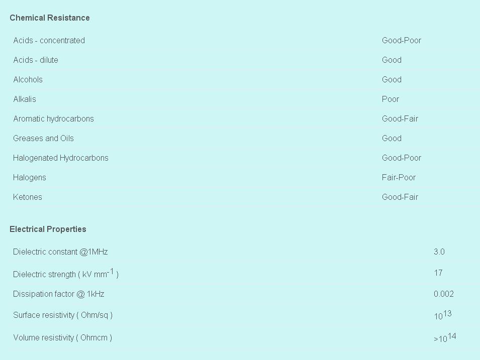
6 Vacuum Seals O-rings: main specifications and locations are presented in the table below: Vacuum Window Table 2: Vacuum seals Epidor. [3] The vacuum window goal is to allow transition (physical, electromagnetic and vacuum) between the signal and the triband feed. For this receiver, a vacuum window made of Mylar (Polyethylene terephthalate film, thickness 0.5 mm) was selected Intermediate stage and radiation shield The intermediate stage is an aluminum plate of 6 mm thickness and 342 mm diameter, screwed onto the first stage of the cold head. Attached to this plate there is an aluminum cylinder to cover the cold stage and reduce the radiation load. The radiation shield is covered with multilayer isolator, MLI (8 layers with a total thickness of 4 mm) to reduce the radiation thermal load between the intermediate and cold stages. The Mylar layers used are NRC-2, crinkled aluminized Mylar film mm, with a reflectivity of The NRC-2 exhibit excellent thermal insulation efficiencies when the pressure inside the receiver is less than 10E-4 mbar (the pressure reach inside the dewar is usually below 10E-6 mbar). On the intermediate stage, there are placed several housekeeping devices: temperature sensor, heating resistor, thermostat and zeolites based vacuum trap. These devices have the following characteristics: - Heating resistor: 100 Ω, 25 W. - Zeolites regeneration resistor: the vacuum trap includes a 100 Ω and 2.5 W regeneration resistor. - Temperature sensor: DT-670 Lakeshore Si-diode. - Thermostat: 70 ± 3. The housekeeping devices allow to achieve a better vacuum inside the cryostat and help to warm up faster the receiver in case it is necessary. Another important element, at the intermediate stage, is the infrared filter. It is located on the top cover of the radiation shield. The infrared filter is used to decrease the thermal load to the cold stage (infrared radiation that goes into the cryostat through the window of the 5
7 vacuum case). It is made of extruded polystyrene foam (3 ± 0.3 mm thickness, W/mK thermal conductivity at 40 C, 35 kg/m3 density). The filter consists of three foam layers separated by nylon washers 0.8 mm Cold stage Figure 3. Intermediate stage design and radiation shield. The cold stage consists of a copper plate of 8 mm thickness screwed onto the second stage of the cold head and other plates, where LNAs, hybrids, couplers, housekeeping devices, etc., are placed. The housekeeping elements have the same specifications than the used for the intermediate stage. The QRFH feed is connected directly to the copper plate to achieve temperatures under 20 K. Figure 4. Cold Cu plate design 6
8 2.4. Amplifier setting-up Figure 5. Cold stage plate designed for LNAs integration. The cryostat will contain broadband low noise amplifiers attached to both QRFH feed outputs. The optimum final setup is still being under study: - Balanced configuration. - Single LNA configuration. Before the amplifiers, connected directly to the feed outputs, there are the directional couplers for the calibration signal injection (noise and phase) Internal DC wiring There are 5 hermetic Fischer connectors at the vacuum case bottom plate: - One of them with 16 pin for monitoring signals and housekeeping. - Four of them with 11 pin for the amplifiers biasing signals. The next figures show the Fischer connectors pin-out (11 and 16 pin): Figure 6: 11 pin Fischer (connector view, red point up). Figure 7: 16 pin Fischer (connector view, red point up). The DC wiring will be done using small section long cables to reduce the load due to conduction. The pin number correspondence between the hermetic fischer connectors and the DB9 and DB15 connectors in the dewar bottom plate is always 1 to 1. 7
9 The next table indicates the pin-out association between connectors. Pin-Out DC connections Yebes Broad-Band receiver: QRFH Receiver House-keeping signals Fischer pin Signal DB25 pin Banana DB25 cart 1 ti ti tc tc tf tf free 8 free 9 calef_on red 5 10 regen_on yellow 1 11 gnd_res black calef_mon red (test) 8 13 regen_mon black (test) 2 14 free 15 free 16 free Table 3: Fischer Connector (C7) 16 pin (housekeeping) correspondence with the DB25 connector. Fischer Pin MDM9 Pin Signal 1 1 Gnd 2 2 Vd1 3 3 Vg1 4 4 Vd2 5 5 Vg2 6 6 Vd3 7 7 Vg3 Table 4: Fischer Connector (C1) 11 pin (A1 LNA) correspondence with the MDM9 connector. Fischer Pin MDM9 Pin Signal 1 1 Gnd 2 2 Vd1 3 3 Vg1 4 4 Vd2 5 5 Vg2 6 6 Vd3 7 7 Vg3 Table 5: Fischer Connector (C2) 11 pin (A2 LNA) correspondence with the MDM9 connector. 8
 11 pin (B2 LNA) correspondence with the MDM9 connector.")
10 Fischer Pin MDM9 Pin Signal 1 1 Gnd 2 2 Vd1 3 3 Vg1 4 4 Vd2 5 5 Vg2 6 6 Vd3 7 7 Vg3 Table 6: Fischer Connector (C3) 11 pin (B1 LNA) correspondence with the MDM9 connector. Fischer Pin MDM9 Pin Signal 1 1 Gnd 2 2 Vd1 3 3 Vg1 4 4 Vd2 5 5 Vg2 6 6 Vd3 7 7 Vg3 Table 7: Fischer Connector (C4) 11 pin (B2 LNA) correspondence with the MDM9 connector. Several pins and wires have been left free taking into account future upgrades (amplifiers changes) Low Noise Amplifiers biasing wiring Next figure show the pin-out for the amplifier biasing connectors: Figure 8. LNAs biasing pin-out. 9
11 Housekeeping wiring Figure 9: House-keeping circuit design. There is a 16 pin Fischer connector placed at the room temperature stage (300 K) for the cryostat internal monitoring signals: heating resistors, zeolites regenerators, temperature sensors and thermostats. Fischer Pin Signal Description 1 Ti+ Intermediate stage temperature sensor (+) 2 Ti- Intermediate stage temperature sensor (-) 3 Tc+ Cold stage temperature sensor (+) 4 Tc- Cold stage temperature sensor (-) 5 Tf+ Feed temperature sensor (+) 6 Tf- Feed temperature sensor (-) 9 Calef_on Signal to activate the heaters 10 Regen_on Signal to activate the zeolites regeneration 11 GND_res Ground 12 Calef_mon Heaters monitoring 13 Regen_mon Regenerators monitoring Table 8. Housekeeping signals description. A cable is supplied to connect the receiver with the different housekeeping signals. One end has the Fischer connector o be plugged to the receiver. The other end contains the following elements: 10
12 QRFH Receiver House-keeping signals Fischer pin Signal DB25 pin Banana DB25 cart 1 ti ti tc tc tf tf free 8 free 9 calef_on Yellow 5 10 regen_on Red 1 11 gnd_res Black calef_mon Black 8 13 regen_mon Red 2 14 free 15 free 16 free Table 9. Housekeeping 5 m cable description. So, there is a cable connecting the receiver (Fischer female connector) with the cart back platen (DB25 female connector). There is another cable connecting the cart back platen (DB25 female connector) with the temperatures monitoring system (Lakeshore DB25 male) and the power supply for the resistors. - DB-25 connector: to Lakeshore 218 system (positions one, two and three) DT 670 sensors. - Banana connectors: to power supply for the receiver heating and zeolites regenerating. 11
. The associated Sumitomo compressor is CNA-61C/D model.")
13 3. Cryogenic system This receiver uses a SHI (Sumitomo Heavy Industries) Cold Head Model SRDK-408S2, with the following characteristics: Figure 10. Typical refrigeration capacity of the model SRDK-408S2 cryocooler (50 Hz). The associated Sumitomo compressor is CNA-61C/D model. 12

14 4. Appendix 4.1. Vacuum transducer and controller 13

15 14 Diseño del Criostato del Receptor de Banda Ancha

16 4.2. Temperature sensors specifications 15

17 4.3. Temperature monitor 16

18 4.4. Vacuum window 17


19 18 Diseño del Criostato del Receptor de Banda Ancha
VGOS MEMO #042 MASSACHUSETTS INSTITUTE OF TECHNOLOGY HAYSTACK OBSERVATORY WESTFORD, MASSACHUSETTS August 22, 2016
 To: From: Subject: VGOS MEMO #042 MASSACHUSETTS INSTITUTE OF TECHNOLOGY HAYSTACK OBSERVATORY WESTFORD, MASSACHUSETTS 01886 Space Geodesy Project August 22, 2016 Ganesh Rajagopalan and Chris Eckert Failure
Cryogenic Systems and Receiver Maintenance
 Cryogenic Systems and Receiver Maintenance Christian Plötz Email: christian.ploetz@bkg.bund.de Federal Agency for Cartography and Geodesy Geodetic Observatory Wettzell Germany Objective Provide basic knowledge
The Low-Noise, Integrated Transformer Helium-4 Dipstick Insert
 The Low-Noise, Integrated Transformer Helium-4 Dipstick Insert Sang Lin Chu Georgia Institute Of Technology 837 State Street N.W. Atlanta, GA 30332 gte813m@prism.gatech.edu, sanglinchu@hotmail.com December
Anne-Laure Fontana, Catherine Boucher, Yves Bortolotti, Florence Cope, Bastien Lefranc, Alessandro Navarrini, Doris Maier, Karl-F.
 Multi-beam SIS Receiver Development Anne-Laure Fontana, Catherine Boucher, Yves Bortolotti, Florence Cope, Bastien Lefranc, Alessandro Navarrini, Doris Maier, Karl-F. Schuster & Irvin Still Institut t
Ku-Band Receiver System for SHAO
 Ku-Band Receiver System for SHAO Overview Brent Willoughby July 2014 Atacama Large Millimeter/submillimeter Array Expanded Very Large Array Robert C. Byrd Green Bank Telescope Very Long Baseline Array
K band Focal Plane Array: Mechanical and Cryogenic Considerations Steve White,Bob Simon, Mike Stennes February 20, 2008 COLD ELECTRONICS
 K band Focal Plane Array: Mechanical and Cryogenic Considerations Steve White,Bob Simon, Mike Stennes February 20, 2008 CRYOGENICS AND DEWAR DESIGN The dewar outside dimension must be less than the 36
AVN Training HartRAO 2016
 AVN Training HartRAO 2016 Microwave 1 Overview Introduction to basic components used in microwave receivers. Performance characteristics of these components. Assembly of components into a complete microwave
Influence of Temperature Variations on the Stability of a Submm Wave Receiver
 Influence of Temperature Variations on the Stability of a Submm Wave A. Baryshev 1, R. Hesper 1, G. Gerlofsma 1, M. Kroug 2, W. Wild 3 1 NOVA/SRON/RuG 2 DIMES/TuD 3 SRON / RuG Abstract Radio astronomy
Micro-manipulated Cryogenic & Vacuum Probe Systems
 Janis micro-manipulated probe stations are designed for non-destructive electrical testing using DC, RF, and fiber-optic probes. They are useful in a variety of fields including semiconductors, MEMS, superconductivity,
Coaxial Line Stretchers
 Coaxial Line Stretchers Frequency range (Note) Maximum Input NOTE: The frequency range will depend on the model. 1.Vibration 2.Shock DC to 10.0 GHz 50 W These coaxial line stretchers maintain an impedance
Optimizing Microwave Signal Transmissions In Extreme Cryogenic Environments Times Microwave Systems SiO2 Products
 Optimizing Microwave Signal Transmissions In Extreme Cryogenic Environments Times Microwave Systems Products Martin Winkler Product Manager Times Microwave Systems 358 Hall Avenue Wallingford, CT 06492
SERIESN50, COAXIAL CONNECTORS
 SERIESN50, COAXIAL CONNECTORS DESCRIPTION CONTENTS PAGE HUBER+SUHNER N connectors are available with 50 and 75 impedance. The frequency range extends to 18 GHz, depending on the connector and cable type.
Frequency Range: MHz. Efficiency: 80% Temperature Range: -20 to 65 C Max VSWR: 3:1. Class: Supply Voltage: 32.0V
 Part Number Revision 0.B Release Date October 19, 2007 Revision Notes Final production release Amplifier Name Technical Specifications Summary Frequency Range: 86-108 MHz P1dB: 500 Watts CW Class: C Supply
Progress on 30K-50K Two-Stage EM PT Cold Finger for Space Applications
 Progress on 30K-50K Two-Stage EM PT Cold Finger for Space Applications T. Prouvé 1, I. Charles 1, H. Leenders 2, J. Mullié 2, J. Tanchon 3, T. Trollier 3, T. Tirolien 4 1 Univ. Grenoble, Alpes, CEA INAC-SBT,
ALMA Interferometer and Band 7 Cartridge
 ALMA Interferometer and Band 7 Cartridge B7 Cartridge designed, assembled and tested by: S. Mahieu, D. Maier (mixer team lead), B. Lazareff (now at IPAG) G. Celestin, J. Chalain, D. Geoffroy, F. Laslaz,
Dinesh Micro Waves & Electronics
 Wave Guide Components RECTANGULAR WAVE GUDES Dinesh Microwaves and Electronics manufacturers of high power waveguide in the microwaves industry, this experience had resulted in designing, manufacturing
Performance evaluation of two RF power limiters based on PIN diodes
 Performance evaluation of two RF power limiters based on PIN diodes Marta Bautista Durán, José A. López-Pérez December 2017 IT-CDT 2017-19 Observatorio de Yebes Apdo. 148, E-19080 Guadalajara SPAIN 1 1
A SUBMILLIMETER SIS RECEIVER COOLED BY A COMPACT STIRLING-YT REFRIGERATOR
 Eighth International Symposium on Space Terahertz Technology. Harvard Universit y. March 1997 A SUBMILLIMETER SIS RECEIVER COOLED BY A COMPACT STIRLING-YT REFRIGERATOR J.Inatani, T.Noguchi, S.C.Shi, and
10. Mini Coax Connectors
 . Connectors The allows multi-pole coaxial data transmission for board-to-board, cableto-board and cable-to-cable applications with protection up to IP65 / IP67. At the same time, applications up to 2.5
Development of a Vibration Measurement Method for Cryocoolers
 REVTEX 3.1 Released September 2 Development of a Vibration Measurement Method for Cryocoolers Takayuki Tomaru, Toshikazu Suzuki, Tomiyoshi Haruyama, Takakazu Shintomi, Akira Yamamoto High Energy Accelerator
4. Superconducting sector magnets for the SRC 4.1 Introduction
 4. Superconducting sector magnets for the SRC 4.1 Introduction The key components for the realization for the SRC are: the superconducting sector magnet and the superconducting bending magnet (SBM) for
A Noise-Temperature Measurement System Using a Cryogenic Attenuator
 TMO Progress Report 42-135 November 15, 1998 A Noise-Temperature Measurement System Using a Cryogenic Attenuator J. E. Fernandez 1 This article describes a method to obtain accurate and repeatable input
Features. = +25 C, +Vdc = +6V, -Vdc = -5V
 HMC-C59 v.59 WIDEBAND LNA MODULE, - 2 GHz Typical Applications The HMC-C59 Wideband LNA is ideal for: Telecom Infrastructure Features Noise Figure:.8 db @ 8 GHz High Gain: 6 db @ 8 GHz PdB Output Power:
SMA Male Connector Crimp/Solder Attachment for RG174, RG316, RG188 Gold Plated
 SMA Male Connector Crimp/Solder Attachment for RG174, RG316, RG188 Gold Plated RF Connectors Technical Data Sheet PE45145 Configuration SMA Male Connector 50 Ohms Straight Body Geometry RG174, RG316, RG188
Study towards cryogenic Phased Array Radar Systems
 Study towards cryogenic Phased Array Radar Systems A. Froehlich, M. Tiesing and N. Ben Bekhti, F. Koenig, S. Putselyk, L. Naumann, F. Rahlf Fraunhofer Institute for High Frequency Physics and Radar Techniques
TNC SERIES General... 4 Interface... 5 Characteristics...6-7
 CONTENTS PAGE TNC SERIES General... 4 Interface... 5 Characteristics...6-7 TNC 50 Ω SERIES Plugs...8-9 Jacks...0- Jacks and receptacles... Receptacles...-4 Adapters... 5 Caps... 6 TNC 75 Ω SERIES Plugs...
MASSACHUSETTS INSTITUTE OF TECHNOLOGY HAYSTACK OBSERVATORY
 To: From: EDGES MEMO #073 MASSACHUSETTS INSTITUTE OF TECHNOLOGY HAYSTACK OBSERVATORY WESTFORD, MASSACHUSETTS 01886 Updated July 16, 2012 Telephone: 781-981-5407 Fax: 781-981-0590 EDGES Group Alan E.E.
Detector Systems. Graeme Carrad
 Detector Systems Graeme Carrad November 2011 The Basic Structure of a typical Radio Telescope Antenna Receiver Conversion Digitiser Signal Processing / Correlator They are much the same CSIRO. Radiotelescope
Radio Telescope Receivers
 Radio Telescope Receivers Alex Dunning 25 th September 2017 CSIRO ASTRONOMY AND SPACE SCIENCE A radio receiver is an electronic device that receives radio waves and converts the information carried by
A Low Noise GHz Amplifier
 A Low Noise 3.4-4.6 GHz Amplifier C. Risacher*, M. Dahlgren*, V. Belitsky* * GARD, Radio & Space Science Department with Onsala Space Observatory, Microtechnology Centre at Chalmers (MC2), Chalmers University
 INDEX Unflanged Elbows 7/8 Male - Male...2 1+5/8 Male - Male...3 1+5/8 Male - Female...4 1+5/8 Female - Female...5 3+1/8 Male - Male...6 Flanged Elbows 7/8...8 1+5/8...9 3+1/8...10 Coaxial Adaptors 7/8
SMA Description Applications Features
 MCX SMA Description SMA connectors are adaptable to interconnection requirements of both systems and components.s - Corm offers a wide variety of cable connectors,receptacles, feed thrus, end launches,
UHV Double-Ended SMA Feedthrough, , Conflat compatible flange
 SMA Interface SMA Interface Grounded and Feedthroughs UHV Double-Ended SMA Feedthrough, 110730, Conflat compatible flange UHV male SMA cable 5 assembly, 110755, Kapton insulated 50-ohm coaxial cable Features
ALMA Band-1: Key Components, Cartridge Design, and Test Plan
 ALMA Band-1: Key Components, Cartridge Design, and Test Plan Yuh-Jing Hwang, Chau-Ching Chiong, Yue-Fang Kuo, Ted Huang, Doug Henke, Marian Pospieszalski, Nicolas Reyes, Ciska Kemper, and Paul Ho ASIAA,
THE CRYOGENIC SYSTEM OF TESLA
 THE CRYOGENIC SYSTEM OF TESLA S. Wolff, DESY, Notkestr. 85, 22607 Hamburg, Germany for the TESLA collaboration Abstract TESLA, a 33 km long 500 GeV centre-of-mass energy superconducting linear collider
Labs. Introduction. Specialty Family
 INC. Labs Introduction Specialty Family Features K-Jumper: Affordable, High Performance Interconnect up to 35 GHz Space-Flex : Semi-Rigid and Flexible Cable Assemblies for S-Level Space T-Flex : Flexible
242, , FAX.
 TEL. 886 2 8994 1601, FAX. 886 2 8994 1602 sales@rfconnector.com.tw, www.rfconnector.com.tw General Information SMA SMB Subminiature Connectors Screw Lock Subminiature Connectors Snap Lock 50 Ω 18 GHz
EVLA Front-End CDR. EVLA Ka-Band (26-40 GHz) Receiver
 Receiver") EVLA Front-End CDR EVLA Ka-Band (26-40 GHz) Receiver 1 EVLA Ka-Band Receiver Overview 1) General Description 2) Block Diagram 3) Noise & Headroom Model 4) Feed & Thermal Gap 5) RF Tree - Phase-Shifter
EVLA Front-End CDR EVLA Ka-Band (26-40 GHz) Receiver 1 EVLA Ka-Band Receiver Overview 1) General Description 2) Block Diagram 3) Noise & Headroom Model 4) Feed & Thermal Gap 5) RF Tree - Phase-Shifter
SMB Connectors. Adaptors-50Ω. Plug to Plug. Jack to Jack. Plug to Jack. Bulkhead Jack to Jack
 SMB Connectors Adaptors-50Ω Plug to Plug 1P-801-00 Jack to Jack 1P-802-00 Plug to Jack 1P-803-00 Bulkhead Jack to Jack 1P-804-18 Mini-SMB 75Ω Straight Plug 1P75-111-00 Cable group RG316 Straight PCB Jack
10. Mini Coax Connectors
 . Connectors The allows multi-pole coaxial data transmission for board-to-board, cable-to-board and cable-to-cable applications with protection up to IP 65 / IP 67. At the same time, applications up to
RF Connectors Technical Data Sheet. Gold over Nickel Plated Beryllium Copper Contact. Size in [11.81 mm] . Weight lbs [3.18 g].
![RF Connectors Technical Data Sheet. Gold over Nickel Plated Beryllium Copper Contact. Size in [11.81 mm] . Weight lbs [3.18 g].](/thumbs/90/101629325.jpg "RF Connectors Technical Data Sheet. Gold over Nickel Plated Beryllium Copper Contact. Size in [11.81 mm] . Weight lbs [3.18 g].") RP SMA Male Connector Solder Attachment for PE-SR402AL, PE-SR402FL, PE-SR402FLJ, PE- SR402TN, RG402, Gold Plated Brass Body RF Connectors Technical Data Sheet PE44724 Configuration SMA Male Reverse Polarity
RP SMA Male Connector Solder Attachment for PE-SR402AL, PE-SR402FL, PE-SR402FLJ, PE- SR402TN, RG402, Gold Plated Brass Body RF Connectors Technical Data Sheet PE44724 Configuration SMA Male Reverse Polarity
The 144MHz Anglian 3 transverter
 The 144MHz Anglian 3 transverter A high performance 144/28MHz transverter G4DDK document issue 1 12/9/16 Introduction Anglian 3 is an update to the 144MHz Anglian 2 transverter. The Anglian 2 is no longer
Raytheon Stirling / PulseTube Cryocooler Maturation Programs
 Raytheon Stirling / PulseTube Cryocooler Maturation Programs C. S. Kirkconnell 1, R. C. Hon 1, and T. Roberts 2 1 Raytheon Space and Airborne Systems El Segundo, CA, 90245, USA 2 Air Force Research Laboratory/VSSS
ED701 General Industry Pressure Transmitter
 ED701 General Industry Pressure Transmitter Standard industrial process connections Complete range of electrical connections 4... 20 ma and Voltage outputs Accuracy: 0.1%, 0.2% and 0.4% FS Quick response
Agilent 8761A/B Microwave Switches
 Agilent 8761A/B Microwave Switches Product Overview Product Description The Agilent Technologies 8761A and 8761B are single-pole, double-throw coaxial switches with excellent electrical and mechanical
RF-LAMBDA LEADER OF RF BROADBAND SOLUTIONS
 Reflective Coaxial SP2T Switch 50 700MHz Electrical Specifications, TA = +25 C, Vdd = +5V/-28V, TTL = 0 / +5V Description Features Wide Band Operation 50-700MHz TTL compatible driver included Fast Switching
NATIONAL RADIO ASTRONOMY OBSERVATORY CHARLOTTESVILLE, VIRGINIA. ELECTRONICS DIVISION INTERNAL REPORT No. 275 CRYOGENIC, HEMT, LOW-NOISE RECEIVERS
 NATIONAL RADIO ASTRONOMY OBSERVATORY CHARLOTTESVILLE, VIRGINIA ELECTRONICS DIVISION INTERNAL REPORT No. 275 CRYOGENIC, HEMT, LOW-NOISE RECEIVERS FOR 1.3 TO 43 GHz RANGE S. WEINREB M. W. POSPIESZALSKI R.
Valve Island with Electronic I/O
 Screw in Temperature /Switch with display for ON/OFF Control Indication, monitoring, transmission and ON/OFF control in one device Extra large display Menu guided parametrisation Complete communication
ngvla Advanced Cryocoolers For ngvla NATIONAL RADIO ASTRONOMY OBSERVATORY Larry D Addario, Caltech ngvlaworkshop, Socorro, 2017 June 26
 NATIONAL RADIO ASTRONOMY OBSERVATORY Advanced Cryocoolers For ngvla Larry D Addario, Caltech ngvlaworkshop, Socorro, 2017 June 26 ngvla Outline How cold do we need to get? Tutorial on cryocoolers (just
and GHz. ECE Radiometer. Technical Description and User Manual
 E-mail: sales@elva-1.com http://www.elva-1.com 26.5-40 and 76.5-90 GHz ECE Radiometer Technical Description and User Manual November 2008 Contents 1. Introduction... 3 2. Parameters and specifications...
DS200ID-CD100. Specification highlights Symbol Unit Min Typ Max. Features. Applications: Linearity error maximum 2 ppm. MPS for particles accelerators
 Ultra-stable, high precision (ppm class) fluxgate technology DS Series current transducer for non-intrusive, isolated DC and AC current measurement up to 370A Features Linearity error maximum 2 ppm 100
RF-LAMBDA LEADER OF RF BROADBAND SOLUTIONS
 Absorptive Coaxial SP3T Switch 0.5-50GHz Electrical Specifications, T A = +25 C, Vdd = +5V/-5V, TTL = 0 / +5V Description PN: SP3T Absorptive Switch Low Power Cold Switching Parameter Min Typ Max Min Typ
Cable transducer Analog output / redundant Measuring length absolute up to 5 m
 Features Magnetic sensing method Resolution: 12 bit Interface analog 0...10 V / 0.. V /...20 ma Measuring length up to m Removable stickers for water outlet Teach inputs Extremely light thanks to housing
Coaxial Line Stretchers
 All non-rohs products have been discontinued, or will be discontinued soon. Please check the products status on the Hirose website RoHS search at www.hirose-connectors.com, or contact your Hirose sales
RP SMA Male Right Angle Connector Solder Attachment for PE-SR402AL, PE-SR402FL, RG402
 RP SMA Male Right Angle Connector Solder Attachment for PE-SR402AL, PE-SR402FL, RG402 RF Connectors Technical Data Sheet PE4790 Configuration SMA Male Reverse Polarity Connector MIL-STD-348 50 Ohms Right
Labs. Introduction. Specialty Family
 INC. Labs Introduction Specialty Family Features K-Jumper: Affordable, High Performance Interconnect up to 35 GHz Sta-Put: Zero Loading Test Cable Space-Flex : Semi-Rigid and Flexible Cable Assemblies
MIL-C-17 Standard RF Coaxial Cable Low Loss & Ultra Low Loss RF Microwave Cable ANTENNA & TEST Cable up to 26.5 GHz
 MIL-C-17 Standard RF Coaxial Cable Low Loss & Ultra Low Loss RF Microwave Cable ANTENNA & TEST Cable up to 26.5 GHz Low Loss Low Density PTFE Dielectric RF Microwave Coaxial Cable Silver Plated Copper
Revision 1.b Release Date July 29, 2007 This data sheet covers models 4379, 4472 Revision Notes Repl 0.d (Rev p/n 250W, B version of Comb)
") Part Number Revision 1.b Release Date July 29, 2007 This data sheet covers models 4379, 4472 Revision Notes Repl 0.d (Rev p/n 250W, B version of Comb) Amplifier Name Technical Specifications Summary Frequency
Part Number Revision 1.b Release Date July 29, 2007 This data sheet covers models 4379, 4472 Revision Notes Repl 0.d (Rev p/n 250W, B version of Comb) Amplifier Name Technical Specifications Summary Frequency
RF Components Product Catalogue
 RF Components Product Catalogue Government and Defence Broadcast Marine, Oil and Gas SNG and VSAT RF Engineering by Design Contents Splitters / Combiners Active Splitters and Combiners Page 3 Passive Splitters
Double-Ridged Waveguide Horn
 Model 3106 200 MHz 2 GHz Uniform Gain Power Handling up to 1.6 kw Model 3115 1 GHz 18 GHz Low VSWR Model 3116 18 GHz 40 GHz Quality Construction M O D E L 3 1 0 6 Double-Ridged Waveguide Horn PROVIDING
2.4mm coaxial connectors for frequency test measurements
 2.4mm coaxial connectors for frequency test measurements 2.4mm Series Functional diagram Straight plug H2.4-P-SS085 Plug side Attenuator PlugJack H2.4-AT (**)-PJ ** 0, 3, 6, 10, 20dB Features 1. Complies
1562 P150-UHF-13. Frequency Range: MHz. Efficiency: 45% Temperature Range: 0 to 70 C Max VSWR: 1.5:1. Supply Voltage: 32.
 1562 Part Number P150-UHF-13 Amplifier Name 1562 P150-UHF-13 Revision 1.f Release Date July 9th 2007 Revision Notes Frequency Range: 470-860 MHz P1dB: 55 Watts CW Class: AB Supply Voltage: 32.0V Gain:
Times Microwave Systems Hermetically Sealed Assemblies
 SCOPE This Specification details the Electrical, Mechanical and Environmental Characteristics of Times Microwave Systems MILTECH 480.48 Diameter Hermetically Sealed Coaxial Transmission Lines. This product
DS2000ICLA. Specification highlights Symbol Unit Min Typ Max. Features. Applications: 1 ppm linearity. MPS for particles accelerators.
 Ultra-stable, high precision (ppm class) fluxgate technology DS Series current transducer for non-intrusive, isolated DC and AC current measurement up to 3000A Features ppm linearity 0 ppm offset Current
High Frequency Single & Multi-chip Modules based on LCP Substrates
 High Frequency Single & Multi-chip Modules based on Substrates Overview Labtech Microwave has produced modules for MMIC s (microwave monolithic integrated circuits) based on (liquid crystal polymer) substrates
Manufacturers of RF and Microwave Components and Assemblies Specialist in RF Filters, Power amplifiers and RF Switches
 Manufacturers of RF and Microwave Components and Assemblies Specialist in RF Filters, Power amplifiers and RF Switches sales@cormic.com www.cormic.com P 724.940.7556 F 724.940.7707 RF & MICROWAVE FILTERS
SECTION 7 R114 / R115 / R116 / R117 / R112
 SECTION 7 7 smb / SMB-LOCK / SMC R114 / R115 / R116 / R117 / R112 Contents SMB Introduction... 7-4 to 7-5 Interface... 7-6 Characteristics... 7-7 to 7-8 Plugs... 7-8 to 7-9 Jacks...7-9 to 7-10 Bulkhead
Thin Film Deposition
 Thin Film Deposition Section Eleven 11 11.1 General Information 2 11.2 Deposition Monitors 3 11.3 Crystal Feedthroughs 4 11.4 s 5 11.5 Cables, s, Crystals & Accessories 6 Nor-Cal Products, Inc. 1967 South
SATELLITE RECEIVING SYSTEM (IF)
") SATELLITE RECEIVING SYSTEM (IF) The Contractor shall supply, install and commission an IF Satellite Receiving System of an approved manufacturer and design, capable of receiving and distributing present
SATELLITE RECEIVING SYSTEM (IF) The Contractor shall supply, install and commission an IF Satellite Receiving System of an approved manufacturer and design, capable of receiving and distributing present
Efficiency: 68% Temperature Range: +0 to 60 C Max VSWR: 5:1. Class: Supply Voltage:
 Part Number Revision 2.C Release Date July 11 2007 Revision Notes - updated new format Amplifier Name Technical Specifications Summary Frequency Range: P1dB: Class: Supply Voltage: 88-108 MHz 750 Watts
Conductivity Transmitter
 Conductivity Transmitter Programmable outputs: two transistor and single or dual analog 4-20 ma Removable backlighted display Universal process connection Type can be combined with... Three cell constants
CTE7000 Series Miniature pressure transmitters
 CTE7 Series FEATURES mbar to 7 bar gage bar to 7 bar absolute,, or output Single supply Field interchangeable Rugged stainless steel housing SERICE Pressure inlet: any non-ionic, non-corrosive media compatible
RF-LAMBDA LEADER OF RF BROADBAND SOLUTIONS
 LEADER OF RF BROADBAND SOLTIONS Absorptive Coaxial SP2T Switch.2 ~ Features Wide Band Operation.2- TTL compatible driver included Fast Switching Speed Low Insertion Loss and High Isolation Customization
PNRRKIT. Portable Networked Re-Radiating Kit Technical Product Data. Features. Description. Utilizes Existing Roof Antenna
 PNRRKIT Portable Networked Re-Radiating Kit Technical Product Data Features Utilizes Existing Roof Antenna Re-Radiating Amplifier with Power Supply Typical Gain 30dB Optional Mounting Kit Hardware Adjustable
141 SMNB Model Series
 HAND Coaxial TM Cable 50Ω DC to 12.5 GHz 141 SMNB Model Series The Big Deal N-Type (F) Bulkhead Connector to SMA (M) Hand Formable Tight Bend-Radius (8mm min.) Ideal for interconnect of assembled systems
db Systems Model 5100A-HS-ICE DME Antenna
 Installation Manual db Systems Model 5100A-HS-ICE DME Antenna HEATED RADOME HIGH PERFORMANCE DME ANTENNA MANUFACTURER db SYSTEMS, INC. 2005 SOUTH TURF SOD ROAD HURRICANE, UT 84737 DATE OF ORIGINAL ISSUE:
Coupling- / Decoupling Network. 150 khz 300 MHz. 150 khz 230 MHz. 10 khz 230 MHz. IEC and CISPR 15 / CISPR 22 IEC
 Coupling- / Decoupling Network 150 khz 300 MHz IEC 61000-4 - 6 and CISPR 15 / CISPR 22 150 khz 230 MHz IEC 61000-4 - 6 10 khz 230 MHz IEC 61000-4 - 6 and IEC 61326-3 - 2 and NE-21 Coupling and decoupling
Centro Astronómico de Yebes
 Centro Astronómico de Yebes CRYOGENIC AMPLIFIER REPORT Cryogenic LNAs for the RAEGE X-Band receiver: YXA 1181, YXA 1182, YXA 1183 Version 2 Centro Astronómico de Yebes Apartado 148 198 Guadalajara España
SECTION 14. DIN 1.0/2.3 / DIN 1.6/5.6 / Type 43 R118 / R120 / R129 / R214
 SECTION 14 14 DIN 1.0/2.3 / DIN 1.6/5.6 / Type 43 R118 / R120 / R129 / R214 Contents DIN 1.0/2.3 Introduction... 14-4 Interface... 14-4 Characteristics Eco... 14-5 Plugs Eco... 14-6 Jacks Eco... 14-6
Frequency Range: MHz. Efficiency: 10% Temperature Range: 0 to 60 C Max VSWR: 5:1. Class: Supply Voltage: 28.0V
 Part Number Revision 1.c Release Date July 24, 2007 Revision Notes Amplifier Name Technical Specifications Summary Frequency Range: 50-88 MHz P1dB: 60 Watts CW Class: A Supply Voltage: 28.0V Gain: 36dB
NATIONAL RADIO ASTRONOMY OBSERVATORY GREEN BANK, WEST VIRGINIA ECCOFOAM AS A DEWAR WAVEGUIDE VACUUM WINDOW. Richard F. Bradley and Roger D.
 NATIONAL RADIO ASTRONOMY OBSERVATORY GREEN BANK, WEST VIRGINIA ELECTRONICS DIVISION TECHNICAL NOTE NO. 125 Title: ECCOFOAM AS A DEWAR WAVEGUIDE VACUUM WINDOW Author(s): Richard F. Bradley and Roger D.
STANDARD COAXIAL CONNECTORS. Eco 7/16 series
 STANDARD COAXIAL CONNECTORS Eco 7/16 series Eco 7/16 INTRODUCTION GENERAL Standard coaxial connectors Screw on coupling Compliant to CECC and IEC standards 50 Ω APPLICATIONS Broadcast RF components (filters,
ph or ORP Transmitter
 ph or ORP Transmitter Programmable outputs: two transistor and single or dual analog 4-20 ma (Process + Temp) Removable backlighted display Universal process connection Compatible with 120 mm ph/ ORP probes
TESLA RF POWER COUPLERS DEVELOPMENT AT DESY.
 TESLA RF POWER COUPLERS DEVELOPMENT AT DESY. Dwersteg B., Kostin D., Lalayan M., Martens C., Möller W.-D., DESY, D-22603 Hamburg, Germany. Abstract Different RF power couplers for the TESLA Test Facility
87415A microwave system amplifier A microwave. system amplifier A microwave system amplifier A microwave.
 20 Amplifiers 83020A microwave 875A microwave 8308A microwave 8307A microwave 83006A microwave 8705C preamplifier 8705B preamplifier 83050/5A microwave The Agilent 83006/07/08/020/050/05A test s offer
High Accuracy Eddy Current Type Displacement Sensor GP-A SERIES. Resolution 0.04 % F.S., Linearity ±0.5 % F.S., IP67g environment resistance
 13 High Accuracy Eddy Current Type Sensor SERIES Related Information General terms and conditions... F- Glossary of terms... P.139 Sensor selection guide... P.9~ General precautions... P.1 PHOTO PHOTO
Pressure Transmitter SIL
 Pressure Transmitter SI Characteristics - TRANSDUCER - Pressure: Range: Output: Accuracy: Temperature of medium: Material enclosure: Pressure connection: Electrical connection: Protection: relative / absolute
Cu 0.37 Brass Cu 0.37 Brass
 To: From: EDGES MEMO #148 MASSACHUSETTS INSTITUTE OF TECHNOLOGY HAYSTACK OBSERVATORY WESTFORD, MASSACHUSETTS 01886 October 7, 2014 Telephone: 781-981-5400 Fax: 781-981-0590 EDGES Group Alan E.E. Rogers
Third Harmonic Superconducting passive cavities in ELETTRA and SLS
 RF superconductivity application to synchrotron radiation light sources Third Harmonic Superconducting passive cavities in ELETTRA and SLS 2 cryomodules (one per machine) with 2 Nb/Cu cavities at 1.5 GHz
OEM miniature resistance thermometer Models TR31-3 and TR31-K, thread-mounted
 Electrical temperature measurement OEM miniature resistance thermometer Models TR31-3 and TR31-K, thread-mounted WIKA data sheet TE 60.31 Applications Machine building, plant and vessel construction Propulsion
LTE high-performance coaxial cables (RG replacement)
") LTE high-performance coaxial cables (RG replacement) Center Conductor: See table below. Dielectric: LTE (extruded low-density PTFE) or low density / composite. Inner Shield: 875-892: None. 900-142: Flat
LTE high-performance coaxial cables (RG replacement) Center Conductor: See table below. Dielectric: LTE (extruded low-density PTFE) or low density / composite. Inner Shield: 875-892: None. 900-142: Flat
Features. = +25 C, +Vdc = +6V, -Vdc = -5V
 v3.7 WIDEBAND LNA MODULE, - 2 GHz amplifiers Typical Applications The Wideband LNA is ideal for: Telecom Infrastructure Microwave Radio & VSAT Military & Space Test Instrumentation Industrial Sensors Functional
Millikelvin measurement platform for SQUIDs and cryogenic sensors
 Cryoconference 2010 Millikelvin measurement platform for SQUIDs and cryogenic sensors M. Schmidt, J. Beyer, D. Drung, J.-H. Storm Physikalisch-Technische Bundesanstalt, Abbe Str. 2-22, 10587 Berlin, Germany
NON-AMPLIFIED HIGH SPEED PHOTODETECTOR USER S GUIDE
 NON-AMPLIFIED HIGH SPEED PHOTODETECTOR USER S GUIDE Thank you for purchasing your Non-amplified High Speed Photodetector. This user s guide will help answer any questions you may have regarding the safe
DTM.OCS.S/N - Modbus Level Transmitter
 Digital Submersible Level Transmitter with Modbus Interface DTM.OCS.S/N - Modbus Level Transmitter CUSTOMER BENEFITS High precision digital level transmitter with standard Modbus interface Fast customization
SURFACE MOUNT HIGH REPEATABILITY, BROADBAND TO-5 RELAYS DPDT DC-4 GHz
 SURFACE MOUNT HIGH REPEATABILITY, BROADBAND TO-5 RELAYS DPDT DC-4 GHz SERIES RELAY TYPE GRF7 GRF73 Repeatable, RF relay Sensitive, repeatable, RF relay DESCRIPTION The ultraminiature GRF7 and GRF73 relays
DSSIU-6-1U. Dedicated 6-channel system interface unit for ultra-stable, high precision fluxgate technology DS series current transducers.
 DSSIU-6-1U Dedicated 6-channel system interface unit for ultra-stable, high precision fluxgate technology DS series current transducers. Powers up to 6 x DS50 to DS2000 at the same time. Supports calibration
EVLA Receiver Issues. EVLA Advisory Committee Meeting, March 19-20, 2009
 EVLA Receiver Issues EVLA Advisory Committee Meeting, March 19-20, 2009 Robert Hayward - Systems Engineer for EVLA Front-Ends Gordon Coutts - Microwave Engineer, Front-End Group Sri Srikanth - Scientist/Research
Couplers for Project X. S. Kazakov, T. Khabiboulline
 Couplers for Project X S. Kazakov, T. Khabiboulline TTC meeting on CW-SRF, 2013 Requirements to Project X couplers Cavity SSR1 (325MHz): Cavity SSR2 (325MHz): Max. energy gain - 2.1 MV, Max. power, 1 ma
EVLA Receivers PDR. (4m, P,) L, S, C BAND RECEIVERS. AuthorDaniel (Mert) Mertely
 L, S, C BAND RECEIVERS. AuthorDaniel (Mert) Mertely") EVLA Receivers PDR (4m, P,) L, S, C BAND RECEIVERS Daniel (Mert) Mertely 1 Trx Projections EVLA RX FREQ RANGES AND OP TEMPS: REQUIRED vs. PROJECTED BND FRQ REQ CURNT CURNT CALC IDR RANGE Tsys (2) Tsys
EVLA Receivers PDR (4m, P,) L, S, C BAND RECEIVERS Daniel (Mert) Mertely 1 Trx Projections EVLA RX FREQ RANGES AND OP TEMPS: REQUIRED vs. PROJECTED BND FRQ REQ CURNT CURNT CALC IDR RANGE Tsys (2) Tsys