EVLA Receiver Issues. EVLA Advisory Committee Meeting, March 19-20, 2009
|
|
|
- Homer West
- 5 years ago
- Views:
Transcription
1 EVLA Receiver Issues EVLA Advisory Committee Meeting, March 19-20, 2009 Robert Hayward - Systems Engineer for EVLA Front-Ends Gordon Coutts - Microwave Engineer, Front-End Group Sri Srikanth - Scientist/Research Engineer, CDL Mike Stennes - Microwave Engineer, Green Bank
2 Past Front-End Issues At the EAC Meeting in Sept 2007, the most pressing issue reported in the EVLA Front-End receiver program was the development of wideband Orthomode Transducers (OMTs) A plan was presented which laid out a roadmap for obtaining Octave band Quadridge OMTs at L, S & C-Band Two paths for developing a compact OMT for X-Band This plan has been implemented and we can now report The L, S & C-Band Quadridge OMT designs are complete The S & C-Band OMTs are now in full production The L-Band OMT is undergoing final cryogenic tests t Two different X-Band OMT designs have been fabricated and are in the process of being evaluated EVLA Advisory Committee Meeting March 19-20,
3 Band L S C X OMT Requirements All EVLA receivers use Low-Loss Circular Polarizers Freq (GHz) Bandwidth Ratio 2.00:1 2.00:1 2.00:1 1.50:1 Circular Polarizer Type Quad-Ridge OMT + 90 degree Hybrid Coupler? Planar or Turnstile Junction? Ku :1 Srikanth Phase-Shifter K :1 + Ka :1 Wollack OMT Q :1 Commercial Sloping Septum R. Hayward EVLA Advisory Committee Meeting March 19-20,
4 Wideband Quadridge OMT Development Past History Paul Lilie began OMT development effort in 2001 Novel square cross-sectionsection OMT structure for L-Band (1-2 GHz) Trapped Mode suppression feature After extensive HFSS simulations, a Version 1 Prototype was machined & preliminary evaluation began in mid 2005 Cryogenic testing began Feb 2006 and this OMT was eventually installed in a modified VLA L-Band Dewar on Ant 14 in Oct 2006 Lilie retired in July 2006 Lisa Locke hired in early 2004 Worked closely with Lilie Helped scale L-Band OMT to C-Band (4-8 GHz) Evaluation of machined Version 1 Prototype began Oct 2006 Resigned in Dec 2006 to return to the NWT Mike Stennes at Green Bank was contracted in May 2007 to work on OMTs Scaled the C-Band design to S-Band (2-4 GHz) Evaluation of Version 1 Prototype began in Jan 2008 R. Hayward EVLA Advisory Committee Meeting March 19-20,
5 Wideband OMT Development Recent History Gordon Coutts hired in Sept 2007 Worked on refining the Lilie Version 1 design for improved performance, including a new taper profile, coaxial probe matching, shorting pins and a method to make the assembly easier and more repeatable C-Band: With Hollis Dinwiddie (ME), the mechanical design was finalized and drawings prepared for mass production C-Band Version 2 began testing April 2008 First EVLA-compliant 4-8 GHz receiver installed on Antenna 2 in May 2008 Total of 7 antennas now outfitted S-Band: With Dinwiddie, Mike Stennes & Jake Scarborough (ME), the mechanical design of the OMT was finalized & and the modifications i necessary to use the old VLA L-Band Dewar were developed S-Band Version 2 began testing July 2008 Prototype S-Band receiver installed on Antenna 28 in Jan 2009 L-Band: L-Band Version 2 began testing Sept 2008 New cryostat designed by Dinwiddie to accommodate the 2.75 foot long OMT (corresponds to 2.32λ max ) Cryogenic evaluation of the Prototype receiver & OMT currently underway R. Hayward EVLA Advisory Committee Meeting March 19-20,


6 OMT Structure Input impedance: f min f max 2 Coax Outputs Circular Waveguide Input z Output y impedance: x 50Ω 2 Coax Outputs z y x 6


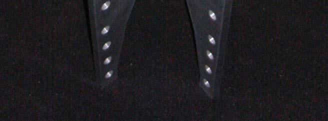

7 S-Band OMT Fabrication Set screw holes for shorting pins Locator block Absorber Coax Feeds S-Band OMT ridge assembly Fully assembled S-Band OMT EVLA Advisory Committee Meeting March 19-20,
8 Refle e ction M ag. ( d B) S-Band OMT Performance Meas. Reflection (Front Probe) Meas. Reflection (Back Probe) Sim. Reflection (Back Probe) Sim. Reflection (Front Probe) Maximum Reflection Specification Freq (GHz) Measured S-Band Return Loss Loss Mag (d db) Insertion Isolation Mag. (db) Insertion Loss (Front Probe) Insertion Loss (Back Probe) Freq (GHz) Measured S-Band OMT Isolation EVLA Advisory Committee Meeting Freq (GHz) March 19-20,
9 L & C-Band OMT Performance Insertion Lo oss (db) Reflection Mag. (db) Insertion Loss (Front Probe) -1.4 Insertion Loss (Front Probe) Freq (GHz) Measured L-Band Insertion Loss Insertion Lo oss (db) Insertion Loss (Front Probe) -1.4 Insertion Loss (Front Probe) Freq (GHz) Measured C-Band Insertion Loss L, S&C-Band OMT Good to Go Reflection (Front Probe) Reflection (Back Probe) Max. Reflection Specification Freq. (GHz) Measured L-Band Return Loss Reflection Mag gnitude (db) Reflection (Front Probe) Reflection (Back Probe) Max. Reflection Specification Freq. (GHz) Measured C-Band Return Loss 9
10 X-Band (8-12 GHz) Transition & EVLA Receivers VLA has a decent (albeit narrow) X-Band system stem These existing GHz receivers have been installed on EVLA antennas Typically used for First Fringes New 8-12 GHz system prototyped t in with production scheduled for 2010 But there are a number of design issues R. Hayward 10 EVLA Advisory Committee Meeting March 19-20, 2008
11 X-Band OMT Development Effort Constraints The 8-12 GHz polarizer needed for the X-Band receiver presents us with several design problems: Quad-ridge OMT is impractical (very small coaxial probes) Ku/K/Ka-style waveguide phase-shifter & OMT too large (over 2 feet long) and would be hard to cool The current GHz VLA X-Band Dewar uses a Model 22 refrigerator and we would prefer to use it rather than a new beefier Model 350 fridge Each EVLA Antenna s 3 compressors can cool two Model 350's plus a Model 22 but not three Model 350's If the new X-Band Rx needs a Model 350, then we have to add a 4 th compressor (~$250K plus increased operating costs) or modify one of the compressors on each antenna for extra capacity (~$30K) but with a sizable risk of reduced reliability The ideal solution would be to have the new wideband polarizer fit inside the existing X-Band Dewar with minimal modifications Next best would be to have a design that might require a new taller and/or fatter Dewar but still allow us to reuse the Model 22 fridge R. Hayward 11 EVLA Advisory Committee Meeting March 19-20, 2008
12 X-Band OMT Development Effort Solutions The bulk of the X-Band OMT development effort has been farmed out to our NRAO sister labs: At the CDL, Sri Srikanth has designed an all-waveguide solution Based on a Mitsubishi turnstile junction design At Green Bank, Mike Stennes has designed a planar OMT Design replaces the coaxial probes with a microstrip circuit and uses two 180 hybrid couplers to combine the signals from the opposing probes Likely to be rather lossy but allows the 90 hybrid (needed to create circular polarization) and the Cal Coupler to be fabricated on the same circuit board Two versions of microstrip circuits are being explored Standard Gold on Alumina High Temperature Superconductor (HTS) Both OMT designs are currently being evaluated By the middle of 2009 we should be in a position to select the design that best meets both our performance requirements and practical constraints so production can begin in early 2010 (schedule driven by budget) R. Hayward 12 EVLA Advisory Committee Meeting March 19-20, 2008


13 Compact OMT Sri Srikanth NRAO-CDL Port 1 Port 3 Port 3 Port 2 Port 2 Top View - Input Bottom View - Outputs CST Microwave Studio Model EVLA Advisory Committee Meeting March 19-20,
14 Compact OMT p Mechanical Design (Mike Solatka, NRAO-CDL)

15 Compact OMT CST Simulations INSERTION LOSS CROSS POLARIZATION INPUT RETURN LOSS


 EVLA")


16 Compact OMT Machined Hardware (Robert Meek, CDL machinist ) EVLA Advisory Committee Meeting March 19-20,
17 Compact OMT - Summary Full waveguide band (8-12 GHz) seems feasible (CST simulation) Return loss -18 db Insertion loss dB Crosspol. -50 db Compact Design : Height = 2.7 & Cross-section = 9.3 diameter Fabrication - all parts are machined (no electroforming required) Length of Circular Polarizer: Circular to square transition = 2.3" Phase Shifter = 8.1" 45 Twist = 3.5 OMT = Dimensions of RF tree L x W = 16.6 x 9.3 Indeed compact but too big to fit in the existing VLA Dewar Will likely provide the solution with lowest-loss and best ellipticity Testing to begin in late March 2009
18 Planar OMT Schematic Diagram Mike Stennes, NRAO-Green Bank OMT Degree Hybrid RCP Cal Coupler 90-Degree Hybrid LCP Cal Coupler 180-Degree Hybrid Schematic diagram of planar OMT EVLA Advisory Committee Meeting March 19-20,


19 Planar OMT Circular Waveguide Interface Planar OMT with circular waveguide interface EVLA Advisory Committee Meeting March 19-20,


")

20 Planar OMT Layout 90 Hybrid Wire Bonding Trace Jump Microstrip Circuit Layout Version 1:Gold on Alumina Version 2:HTS - YBCO/MgO (Yttrium Barium Copper Oxide on a Magnesium Oxide buffer Layer) EVLA Advisory Committee Meeting March 19-20,


21 Planar OMT Package Photograph of the OMT Prototype #1 Mechanical model of cryostat layout EVLA Advisory Committee Meeting March 19-20,
22 Degree Hybrid: Amplitude Balance (Model) 180 Degree Hybrid: Phase Difference (Model) Planar OMT M. Stennes 1/21/2009 M. Stennes 1/21/ Simulations and Early Test Results Waveguide Probes: Return Loss M. Stennes 12/13/2008 Measured Model Waveguide probes Sii, db EVLA X-Band 90-Deg Hybrid Coupler Amplitude Balance M. Stennes 2/21/ Hybrid Coupler 90 Hybrid Coupler Measured Model Frequency, GHz Sii, db EVLA X-Band 90-Deg Hybrid Coupler Phase Balance M. Stennes 2/21/2009 Measured Model Frequency, GHz EVLA Advisory Committee Meeting March 19-20,
23 Planar OMT Estimates Frequency (GHz) LNA Noise Temperature Receiver Temperature (K) Au/Alumina HTS Item Au/Alumina HTS Microstrip circuits Gold plating of chip carriers CDL 600 G10 fiberglass Brass, aluminum blocks Kovar sheet Totals $445 $3,220 EVLA Advisory Committee Meeting March 19-20,
24 Planar OMT Parameter Au/Alumina at Room Temperature Au/Alumina at Cryogenic Temperature HTS at Cryogenic Temperature Mechanical Fit of OMT Done Done Done Matching dissimilar coefficients of thermal expansion (alumina & MgO substrates vs. Done Done Done brass housings) to avoid breakage Hermetic Packaging of YBCO film TBD Return Loss 14 db TBD TBD Insertion Loss 1.5 db TBD TBD Polarization Isolation 16 db TBD TBD Still to come (March April 2009): Additional tests on Au/Alumina OMT Cryogenic tests of Au/Alumina OMT More testing of HTS circuits Cryogenic tests of HTS OMT EVLA Advisory Committee Meeting March 19-20,
25 How Do We Decide on Which X-Band OMT to Adopt? For the Planar OMT design, which has the highest risk, we will have full system tests in a modified VLA receiver. Including a comparison of Au/Alumina versus HTS circuits For the all-waveguide Compact OMT design, we will have bench tests of the IL & RL of the various components in the RF tree. Will not have any cryogenic tests (since this would require a brand new cryostat to be designed and built) But we can easily predict the cryogenic performance of an allwaveguide circular polarizer based on the K & Ka-Band designs So we will have to compare the cryogenic performance of the Planar OMT in a prototype Rx with bench tests of a warm Compact OMT As the performance of the Planar design is much more critical on temperature (especially the HTS option), this plan works for us EVLA Advisory Committee Meeting March 19-20,

")
 K-Band 18-26.")

26 VLA/EVLA EVLA Project Book - T Rx Requirements (Band Center) Band L S C X Ku K Ka Q T Rx versus Frequency T Rx Simple Noise Model 45 L-Band 1-2 GHz(Interim) S-Band 2-4 GHz 40 C-Band 4-8 GHz X-Band 8-12 GHz (VLA) Receiver Temperature (K K) L#32(i) Ku-Band GHz (N/A) K-Band GHz Ka-Band GHz Q-Band GHz Q#18 X#01(t) A# S#01 C#20 K# Frequency (GHz) T Rx = m F + b ; m = 0.5ºK/ GHz ; b = 8ºK
27 Receiver Production Status Summary (as of March 2009) Interim EVLA Comment Antennas 21 Target to complete upgrades in 2010 Q3 L (1 2 GHz) 21 0 Prototype testing; Production begins 2009 Q2 S (2 4 GHz) 1 Prototype evaluated; Production underway C (4 8 GHz) 14 7 Wideband Rx Production/Retrofits underway X (8 12 GHz) 21 0 OMT Testing & Rx Prototyping; Production 2010 Q1 Ku (12 18 GHz 0 Prototype Rx being assembled; Production 2009 Q4 K (18 26 GHz) 21 Full Production Ka (26 40 GHz) 8 Accelerated Production (1/month) Q (40 50 GHz) 21 Full Production EVLA Advisory Committee Meeting March 19-20,
28 Prototype L-Band Receiver New cryostat designed by Hollis Dinwiddie to accommodate the 2.75 foot long OMT Hope to use a Model 350 fridge (backup plan = Model 1020) First cool-down March 2009 Future tests include Cryogenic RF Axial Ratio EVLA Advisory Committee Meeting March 19-20,
29 Questions? R. Hayward 29 EVLA Advisory Committee Meeting March 19-20, 2008
Atacama Large Millimeter/submillimeter Array Expanded Very Large Array Robert C. Byrd Green Bank Telescope Very Long Baseline Array
 Atacama Large Millimeter/submillimeter Array Expanded Very Large Array Robert C. Byrd Green Bank Telescope Very Long Baseline Array A Planar OMT for the 8-12 GHz Receiver Front-End Michael Stennes October
EVLA Front-End CDR. EVLA Ka-Band (26-40 GHz) Receiver
 Receiver") EVLA Front-End CDR EVLA Ka-Band (26-40 GHz) Receiver 1 EVLA Ka-Band Receiver Overview 1) General Description 2) Block Diagram 3) Noise & Headroom Model 4) Feed & Thermal Gap 5) RF Tree - Phase-Shifter
EVLA Front-End CDR EVLA Ka-Band (26-40 GHz) Receiver 1 EVLA Ka-Band Receiver Overview 1) General Description 2) Block Diagram 3) Noise & Headroom Model 4) Feed & Thermal Gap 5) RF Tree - Phase-Shifter
EVLA Receivers PDR. (4m, P,) L, S, C BAND RECEIVERS. AuthorDaniel (Mert) Mertely
 L, S, C BAND RECEIVERS. AuthorDaniel (Mert) Mertely") EVLA Receivers PDR (4m, P,) L, S, C BAND RECEIVERS Daniel (Mert) Mertely 1 Trx Projections EVLA RX FREQ RANGES AND OP TEMPS: REQUIRED vs. PROJECTED BND FRQ REQ CURNT CURNT CALC IDR RANGE Tsys (2) Tsys
EVLA Receivers PDR (4m, P,) L, S, C BAND RECEIVERS Daniel (Mert) Mertely 1 Trx Projections EVLA RX FREQ RANGES AND OP TEMPS: REQUIRED vs. PROJECTED BND FRQ REQ CURNT CURNT CALC IDR RANGE Tsys (2) Tsys
Turnstile Junction Orthomode Transducer An option for EVLA X-Band Receiver X-Band OMT Design Review Meeting; AOC, Socorro; October1, 2009
 Turnstile Junction Orthomode Transducer An option for EVLA X-Band Receiver X-Band OMT Design Review Meeting; AOC, Socorro; October1, 2009 Sivasankaran Srikanth, Miles Solatka & Michael Meek Scientist/Research
NATIONAL RADIO ASTRONOMY OBSERVATORY Socorro, NM ELECTRONICS DIVISION TECHNICAL NOTE NO. 217
 NATIONAL RADIO ASTRONOMY OBSERVATORY Socorro, NM ELECTRONICS DIVISION TECHNICAL NOTE NO. 217 Preliminary Measured Results of a Diagonal Quadruple-Ridged Ku-Band OMT Gordon Coutts November 29, 21 Preliminary
EVLA Front-End CDR. Overview & System Requirements
 EVLA Front-End CDR Overview & System Requirements 1 Overview & System Requirements Introduction to the EVLA Front-End Task EVLA vs. VLA Feeds Receivers System Requirements, including: System Temperatures
EVLA Front-End CDR. Plans for S (2-4), X (8-12) & Ku (12-18 GHz) Receiver Bands
, X (8-12) & Ku (12-18 GHz) Receiver Bands") EVLA Front-End CDR Plans for S (2-4), X (8-12) & Ku (12-18 GHz) Receiver Bands 1 Contents S-Band Receiver EVLA Design X-Band Receiver EVLA Design EVLA Transition Ku-Band Receiver EVLA Design 2 EVLA S-Band
EVLA Front-End CDR Plans for S (2-4), X (8-12) & Ku (12-18 GHz) Receiver Bands 1 Contents S-Band Receiver EVLA Design X-Band Receiver EVLA Design EVLA Transition Ku-Band Receiver EVLA Design 2 EVLA S-Band
EVLA Memo 151 EVLA Antenna Polarization at L, S, C, and X Bands
 EVLA Memo 11 EVLA Antenna Polarization at L, S, C, and X Bands Rick Perley and Bob Hayward April 28, 211 Abstract The method described in EVLA Memo #131 for determining absolute antenna cross-polarization
NATIONAL RADIO ASTRONOMY OBSERVATORY Socorro, NM ELECTRONICS DIVISION TECHNICAL NOTE NO. 217
 NATIONAL RADIO ASTRONOMY OBSERVATORY Socorro, NM ELECTRONICS DIVISION TECHNICAL NOTE NO. 217 Preliminary Measured Results of a Diagonal Quadruple-Ridged Ku-Band OMT Gordon Courts November 29,2010 Preliminary
5 RECEIVERS TABLE TBD: EVLA RECEIVER FREQUENCY RANGES AND OPERATING TEMPERATURES
 EVLA Project Book, Chapter 5. 5 RECEIVERS Robert Hayward, Ed Szpindor, and Daniel J. Mertely Last changed 2001-Oct-30 Revision History 2001-July-01: Initial release. 2001-Oct-01: Sys-def & detail added.
EVLA Memo 60. The Circular Polarization Characteristics of the New VLA K-Band Receiver System
 EVLA Memo 6 The Circular Polarization Characteristics of the New VLA K-Band Receiver System Robert Hayward, Edward Szpindor, Darrell Hicks National Radio Astronomy Observatory 18 June 23 Abstract : The
K band Focal Plane Array: Mechanical and Cryogenic Considerations Steve White,Bob Simon, Mike Stennes February 20, 2008 COLD ELECTRONICS
 K band Focal Plane Array: Mechanical and Cryogenic Considerations Steve White,Bob Simon, Mike Stennes February 20, 2008 CRYOGENICS AND DEWAR DESIGN The dewar outside dimension must be less than the 36
Development of a Wideband Ortho-Mode Transducer
 Development of a Wideband Ortho-Mode Transducer Dirk de Villiers University of Stellenbosch 03 December 2008 Departement Elektriese en Elektroniese Ingenieurswese Department of Electrical and Electronic
A Turnstile Junction Waveguide Orthomode Transducer for the 1 mm Band
 A Turnstile Junction Waveguide Orthomode Transducer for the 1 mm Band Alessandro Navarrini, Richard L. Plambeck, and Daning Chow Abstract We describe the design and construction of a waveguide orthomode
Design of Wideband Quad-Ridged Waveguide Orthomode Transducer at L-Band
 Progress In Electromagnetics Research C, Vol. 72, 115 122, 217 Design of Wideband Quad-Ridged Waveguide Orthomode Transducer at L-Band Jin Fan 1, 2, 3, *,YihuaYan 3, 4, Chengjin Jin 1, 2,DezhiZhan 1, 2,
EVLA Memo #119 Wide-Band Sensitivity and Frequency Coverage of the EVLA and VLA L-Band Receivers
 EVLA Memo #119 Wide-Band Sensitivity and Frequency Coverage of the EVLA and VLA L-Band Receivers Rick Perley and Bob Hayward January 17, 8 Abstract We determine the sensitivities of the EVLA and VLA antennas
ALMA MEMO #360 Design of Sideband Separation SIS Mixer for 3 mm Band
 ALMA MEMO #360 Design of Sideband Separation SIS Mixer for 3 mm Band V. Vassilev and V. Belitsky Onsala Space Observatory, Chalmers University of Technology ABSTRACT As a part of Onsala development of
Modular High Power Ku-Band Polarisation Devices for Space Applications. Philipp Kohl
 Modular High Power Ku-Band Polarisation Devices for Space Applications Philipp Kohl 28-29.04.2015 Outline Motivation Mission Scenarios Investigated Polarisation Devices Polarisation Device Principle Requirements
Summary Report / EVLA FE PDR
 Summary Report / EVLA FE PDR This report is a summary of the findings of the EVLA FE PDR Review Panel and the responses by the Task Leader. The report is based on a top level presentation of the design
SAGE Millimeter, Inc.
 Description: Model SAF-2434233-328-S1-28-DP is a dual polarized, WR-28 scalar feed horn antenna assembly that covers several popular G bands in the frequency range of 24 to 42 GHz. The antenna features
University, 50 Nanyang Avenue, Singapore , Singapore. Industrial Road, ST Electronics Paya Lebar Building, Singapore , Singapore
 Progress In Electromagnetics Research Letters, Vol. 27, 1 8, 211 DUAL-BAND ORTHO-MODE TRANSDUCER WITH IRREGULARLY SHAPED DIAPHRAGM Y. Tao 1, Z. Shen 1, *, and G. Liu 2 1 School of Electrical and Electronic
ALMA Band 1. Charles Cunningham and Stéphane Claude. IRMMW-THZ 2005, Williamsburg. IRMMW-THZ 2005, Williamsburg
 ALMA Band 1 Charles Cunningham and Stéphane Claude Canadian Users - ALMA Canadian LRP 2010 The Atacama Large Millimetre Array is the top priority in LRP2000 The Atacama Large Millimetre Array (ALMA) is
Transmitarrays, reflectarrays and phase shifters for wireless communication systems. Pablo Padilla de la Torre Universidad de Granada
 Transmitarrays, reflectarrays and phase shifters for wireless communication systems Pablo Padilla de la Torre Universidad de Granada Outline 1. Introduction to Transmitarray and Reflectarray structures
Figure 1 Schematic diagram of a balanced amplifier using two quadrature hybrids (eg Lange Couplers).
.") 1 of 14 Balanced Amplifiers The single amplifier meets the specification for noise figure and again but fails to meet the return loss specification due to the large mis-matches on the input & outputs.
1 of 14 Balanced Amplifiers The single amplifier meets the specification for noise figure and again but fails to meet the return loss specification due to the large mis-matches on the input & outputs.
Full-Waveguide Band Orthomode Transducer for the 3 mm and 1 mm Bands. 2 Fabrication and Testing of 3 mm Band OMT
 14th International S y mposium on Space Terahertf. Technology Full-Waveguide Band Orthomode Transducer for the 3 mm and 1 mm Bands Gopal Narayanan l, and Neal Erickson Department of Astronomy, University
A HIGH-POWER LOW-LOSS MULTIPORT RADIAL WAVEGUIDE POWER DIVIDER
 Progress In Electromagnetics Research Letters, Vol. 31, 189 198, 2012 A HIGH-POWER LOW-LOSS MULTIPORT RADIAL WAVEGUIDE POWER DIVIDER X.-Q. Li *, Q.-X. Liu, and J.-Q. Zhang School of Physical Science and
A Broadband W-band Orthomode Transducer for KVN Polarization Observations
 Technical Paper J. Astron. Space Sci. 30(4), 345-353 (2013) A Broadband W-band Orthomode Transducer for KVN Polarization Observations Moon-Hee Chung, Do-Heung Je, Seung-Rae Kim Korea Astronomy & Space
Dinesh Micro Waves & Electronics
 Wave Guide Components RECTANGULAR WAVE GUDES Dinesh Microwaves and Electronics manufacturers of high power waveguide in the microwaves industry, this experience had resulted in designing, manufacturing
Micromachined microwave circuits at Birmingham. M J Lancaster P S Hall, P Gardner, F Huang, Y Wang, M Ke K Jiang, P Prewett
 Micromachined microwave circuits at Birmingham M J Lancaster P S Hall, P Gardner, F Huang, Y Wang, M Ke K Jiang, P Prewett Department of Electronic, Electrical and Computer Engineering and Department of
Wideband Passive Circuits for Sideband Separating Receivers
 Wideband Passive Circuits for Sideband Separating Receivers Hawal Rashid 1*, Denis Meledin 1, Vincent Desmaris 1, and Victor Belisky 1 1 Group for Advanced Receiver Development (GARD), Chalmers University,
ENGAT00000 to ENGAT00010
 Wideband Fixed Attenuator Family, DIE, DC to 50 GHz ENGAT00000 / 00001 / 00002 / 00003 / 00004 / 00005 / 00006 / 00007 / 00008 / 00009 / 00010 Typical Applications ENGAT00000 to ENGAT00010 Features Space
A DUAL-PORTED PROBE FOR PLANAR NEAR-FIELD MEASUREMENTS
 A DUAL-PORTED PROBE FOR PLANAR NEAR-FIELD MEASUREMENTS W. Keith Dishman, Doren W. Hess, and A. Renee Koster ABSTRACT A dual-linearly polarized probe developed for use in planar near-field antenna measurements
RESEARCH AND DESIGN OF QUADRUPLE-RIDGED HORN ANTENNA. of Aeronautics and Astronautics, Nanjing , China
 Progress In Electromagnetics Research Letters, Vol. 37, 21 28, 2013 RESEARCH AND DESIGN OF QUADRUPLE-RIDGED HORN ANTENNA Jianhua Liu 1, Yonggang Zhou 1, 2, *, and Jun Zhu 1 1 College of Electronic and
MICROSTRIP PHASE INVERTER USING INTERDIGI- TAL STRIP LINES AND DEFECTED GROUND
 Progress In Electromagnetics Research Letters, Vol. 29, 167 173, 212 MICROSTRIP PHASE INVERTER USING INTERDIGI- TAL STRIP LINES AND DEFECTED GROUND X.-C. Zhang 1, 2, *, C.-H. Liang 1, and J.-W. Xie 2 1
A BROADBAND POLARIZATION SELECTABLE FEED FOR COMPACT RANGE APPLICATIONS
 A BROADBAND POLARIZATION SELECTABLE FEED FOR COMPACT RANGE APPLICATIONS Carl W. Sirles ATDS Howland 454 Atwater Court, Suite 17 Buford, GA 3518 Abstract Many aircraft radome structures are designed to
insert link to the published version of your paper
 Citation Niels Van Thienen, Wouter Steyaert, Yang Zhang, Patrick Reynaert, (215), On-chip and In-package Antennas for mm-wave CMOS Circuits Proceedings of the 9th European Conference on Antennas and Propagation
Phased Array Polarization Switches
 APPLICATION NOTE March 2003 Page 1 of 9 Application Note POL-1 Phased Array Polarization Switches PREPARED BY: EMS TECHNOLOGIES, INC. SPACE AND TECHNOLOGY - ATLANTA 660 ENGINEERING DRIVE P.O. BOX 7700
Newsletter 5.4. New Antennas. The profiled horns. Antenna Magus Version 5.4 released! May 2015
 Newsletter 5.4 May 215 Antenna Magus Version 5.4 released! Version 5.4 sees the release of eleven new antennas (taking the total number of antennas to 277) as well as a number of new features, improvements
Two octaves bandwidth passive balun for the eleven feed for reflector antennas Zamanifekri, A.; Yang, J.
 Two octaves bandwidth passive balun for the eleven feed for reflector antennas Zamanifekri, A.; Yang, J. Published in: Proceedings of 2010 IEEE International Symposium on Antennas and Propagation, Toronto,
A DUAL-PORTED, DUAL-POLARIZED SPHERICAL NEAR-FIELD PROBE
 A DUAL-PORTED, DUAL-POLARIZED SPHERICAL NEAR-FIELD PROBE by J. R. Jones and D. P. Hardin Scientific-Atlanta, Inc. Spherical near-field testing of antennas requires the acquisition of a great volume of
High-Performance Dual-Circularly Polarized Reflector Antenna Feed
 High-Performance Dual-Circularly Polarized Reflector Antenna Feed Joo-Young Lim, Jargalsaikhan Nyambayar, Je-Young Yun, Dong-Hyun Kim, Tae-Hyung Kim, Bierng-Chearl Ahn, and Jae-Hoon Bang This paper presents
ACompactN-Way Wilkinson Power Divider Using a Novel Coaxial Cable Implementation for VHF Band
 Progress In Electromagnetics Research Letters, Vol. 62, 49 55, 2016 ACompactN-Way Wilkinson Power Divider Using a Novel Coaxial Cable Implementation for VHF Band S. S. Kakatkar *,PrafullIrpache,andK.P.Ray
SAGE Millimeter, Inc.
 Description: Model SAM-5735930395-15-L1-4W is a linear polarized, 58 GHz microstrip patch 1 x 4 array antenna. The antenna array implements four individual antenna ports so that beamforming can be achieved
DOUBLE-RIDGED ANTENNA FOR WIDEBAND APPLI- CATIONS. A. R. Mallahzadeh and A. Imani Electrical Engineering Department Shahed University Tehran, Iran
 Progress In Electromagnetics Research, PIER 91, 273 285, 2009 DOUBLE-RIDGED ANTENNA FOR WIDEBAND APPLI- CATIONS A. R. Mallahzadeh and A. Imani Electrical Engineering Department Shahed University Tehran,
ALMA Interferometer and Band 7 Cartridge
 ALMA Interferometer and Band 7 Cartridge B7 Cartridge designed, assembled and tested by: S. Mahieu, D. Maier (mixer team lead), B. Lazareff (now at IPAG) G. Celestin, J. Chalain, D. Geoffroy, F. Laslaz,
RF Technologies for Space Applications Oscar A. Peverini
 SATCOM research activities @ CNR-IEIIT RF Technologies for Space Applications Oscar A. Peverini Introduction Development of radio-frequency antenna-feed systems for satellite applications in the framework
A broadband 180 hybrid ring coupler using a microstrip-to-slotline inverter Riaan Ferreira and Johan Joubert
 A broadband 180 hybrid ring coupler using a microstrip-to-slotline inverter Riaan Ferreira and Johan Joubert Centre for Electromagnetism, Department of EEC Engineering, University of Pretoria, Pretoria,
3dB HYBRID COUPLER. Amplitude Balance db (max) ± ± to +85
 ± ± to +85") FEATURES High Power Low Profile Surface Mount Package Very Low Insertion Loss Excellent Amplitude and Phase Balance High Isolation RoHS Tape and Reel for High Volume Production APPLICATIONS Power Amplifiers
FEATURES High Power Low Profile Surface Mount Package Very Low Insertion Loss Excellent Amplitude and Phase Balance High Isolation RoHS Tape and Reel for High Volume Production APPLICATIONS Power Amplifiers
2 to 4 GHz Frequency Discriminator for RF Front-End Instantaneous Frequency Measurement Receivers
 Progress In Electromagnetics Research C, Vol. 73, 27 36, 217 2 to 4 GHz Frequency Discriminator for RF Front-End Instantaneous Frequency Measurement Receivers Hazem Deeb 1, *,KhaledYazbek 2, and Adnan
Research Article Compact and Wideband Parallel-Strip 180 Hybrid Coupler with Arbitrary Power Division Ratios
 Microwave Science and Technology Volume 13, Article ID 56734, 1 pages http://dx.doi.org/1.1155/13/56734 Research Article Compact and Wideband Parallel-Strip 18 Hybrid Coupler with Arbitrary Power Division
Bandpass-Response Power Divider with High Isolation
 Progress In Electromagnetics Research Letters, Vol. 46, 43 48, 2014 Bandpass-Response Power Divider with High Isolation Long Xiao *, Hao Peng, and Tao Yang Abstract A novel wideband multilayer power divider
with a Suspended Stripline Feeding
 Wide Band and High Gain Planar Array with a Suspended Stripline Feeding Network N. Daviduvitz, U. Zohar and R. Shavit Dept. of Electrical and Computer Engineering Ben Gurion University i of the Negev,
Design of Tri-frequency Mode Transducer
 78 Design of Tri-frequency Mode Transducer V. K. Singh, S. B. Chakrabarty Microwave Sensors Antenna Division, Antenna Systems Area, Space Applications Centre, Indian Space Research Organization, Ahmedabad-3815,
Ku-Band Receiver System for SHAO
 Ku-Band Receiver System for SHAO Overview Brent Willoughby July 2014 Atacama Large Millimeter/submillimeter Array Expanded Very Large Array Robert C. Byrd Green Bank Telescope Very Long Baseline Array
Development of a Smooth Taper Double-Ridge Waveguide Orthomode Transducer for a New 100 GHz Band Z-Machine Receiver for the NRO 45-m Radio Telescope
 PUBLICATIONS OF THE ASTRONOMICAL SOCIETY OF THE PACIFIC, 125:213 217, 2013 February 2013. The Astronomical Society of the Pacific. All rights reserved. Printed in U.S.A. Development of a Smooth Taper Double-Ridge
Chapter 5. Array of Star Spirals
 Chapter 5. Array of Star Spirals The star spiral was introduced in the previous chapter and it compared well with the circular Archimedean spiral. This chapter will examine the star spiral in an array
RF Components Product Catalogue
 RF Components Product Catalogue Government and Defence Broadcast Marine, Oil and Gas SNG and VSAT RF Engineering by Design Contents Splitters / Combiners Active Splitters and Combiners Page 3 Passive Splitters
Return loss (db) Insertion loss (db) .56±.06 TBD. GND / DC Feed 1 + RF GND 2. Unbalanced Port Balanced Port Balanced Port.
 Insertion loss (db) .56±.06 TBD. GND / DC Feed 1 + RF GND 2. Unbalanced Port Balanced Port Balanced Port.") Model BD6N5AHF Ultra Low Profile 44 Balun 5Ω to Ω Balanced Description The BD6N5AHF is a low cost, low profile sub-miniature unbalanced to balanced transformer designed for differential inputs and output
Model BD6N5AHF Ultra Low Profile 44 Balun 5Ω to Ω Balanced Description The BD6N5AHF is a low cost, low profile sub-miniature unbalanced to balanced transformer designed for differential inputs and output
SPECIFICATION. Low Profile Stacked Patch Antenna. Highest Accuracy, Lowest Profile Low Axial Ratio. Wideband GNSS Antenna. GPS L1+L2 Band Operation
 SPECIFICATION Patent Pending Part No: GPDF.47.8.A.02 Product Name: Embedded 47.5*47.5*8mm GPS L1/L2 Low Profile Stacked Patch Antenna Features: Highest Accuracy, Lowest Profile Low Axial Ratio Wideband
Development Status of KSTAR LHCD System
 Development Status of KSTAR LHCD System September 24, 2004 Y. S. Bae,, M. H. Cho, W. Namkung Plasma Sheath Lab. Department of Physics, Pohang University of Science and Technology LHCD system overview Objectives
SMT Hybrid Couplers, RF Parameters and Applications
 SMT Hybrid Couplers, RF Parameters and Applications A 90 degree hybrid coupler is a four-port device used to equally split an input signal into two signals with a 90 degree phase shift between them. The
High Power 12-Element Triangular-Grid Rectangular Radial Line Helical Array Antenna
 Progress In Electromagnetics Research C, Vol. 55, 17 24, 2014 High Power 12-Element Triangular-Grid Rectangular Radial Line Helical Array Antenna Xiang-Qiang Li *, Qing-Xiang Liu, and Jian-Qiong Zhang
Broadband Rectangular Waveguide to GCPW Transition
 Progress In Electromagnetics Research Letters, Vol. 46, 107 112, 2014 Broadband Rectangular Waveguide to GCPW Transition Jun Dong 1, *, Tao Yang 1, Yu Liu 1, Ziqiang Yang 1, and Yihong Zhou 2 Abstract
Dual Feed Microstrip Patch Antenna for Wlan Applications
 IOSR Journal of Electronics and Communication Engineering (IOSR-JECE) e-issn: 2278-2834,p- ISSN: 2278-8735.Volume 10, Issue 5, Ver. I (Sep - Oct.2015), PP 01-05 www.iosrjournals.org Dual Feed Microstrip
Octave Bandwidth Printed Circuit Phased Array Element
 Octave Bandwidth Printed Circuit Phased Array Element Paul G. Elliot, Lead Engineer MITRE Corporation Bedford, MA 01720 Anatoliy E. Rzhanov *, Sr. Scientist Magnetic Sciences Acton, MA 01720 Abstract A
Newsletter 3.1. Antenna Magus version 3.1 released! New antennas in the database. Square pin-fed septum horn. July 2011
 Newsletter 3.1 July 2011 Antenna Magus version 3.1 released! Antenna Magus 3.0 was such a feature laden release that not all of the new features could be mentioned in the newsletter, so we decided to rather
L-BAND COPLANAR SLOT LOOP ANTENNA FOR INET APPLICATIONS
 L-BAND COPLANAR SLOT LOOP ANTENNA FOR INET APPLICATIONS Jeyasingh Nithianandam Electrical and Computer Engineering Department Morgan State University, 500 Perring Parkway, Baltimore, Maryland 5 ABSTRACT
A Spiral Antenna with Integrated Parallel-Plane Feeding Structure
 Progress In Electromagnetics Research Letters, Vol. 45, 45 50, 2014 A Spiral Antenna with Integrated Parallel-Plane Feeding Structure Huifen Huang and Zonglin Lv * Abstract In practical applications, the
Combined Band MHz. Fig. 1 Typical Diplexer Filter Combiner Fig. 2 Typical Diplexer Combiner
 Choosing the Best Power Divider for the Task of Signal Combining As systems become more and more complex, choosing how best to combine two or more RF signals has become a far more difficult question to
A Miniaturized Multi-Channel TR Module Design Based on Silicon Substrate
 Progress In Electromagnetics Research Letters, Vol. 74, 117 123, 2018 A Miniaturized Multi-Channel TR Module Design Based on Silicon Substrate Jun Zhou 1, 2, *, Jiapeng Yang 1, Donglei Zhao 1, and Dongsheng
National Astronomy and Ionosphere Center Research and Development Laboratory 124 Maple Ave Ithaca, NY TECHNICAL REPORT
 National Astronomy and Ionosphere Center Research and Development Laboratory 124 Maple Ave Ithaca, NY 14867 TECHNICAL REPORT April 21, 1999 To: NAIC Staff From: Eugene Lauria Subj: Trap issue in reference
Microwave Components and Assemblies P A S Q U A L I
 Microwave Components and Assemblies P A S Q U A L I m i c r o w a v e s y s t e m s 01 GRUPPO PASQUALI IS: P A S Q U A L I m i c r o w a v e s y s t e m s Microwave components manufacturing and mechanical
Broadband Balanced Microstrip Antenna Fed by a Waveguide Coupler
 278 Broadband Balanced Microstrip Antenna Fed by a Waveguide Coupler R. Gotfrid*, Z. Luvitzky*, H. Matzner* and E. Levine** * HIT, Holon Institute of Technology Department of Communication Engineering,
NATIONAL RADIO ASTRONOMY OBSERVATORY CHARLOTTESVILLE, VIRGINIA. ELECTRONICS DIVISION INTERNAL REPORT No. 275 CRYOGENIC, HEMT, LOW-NOISE RECEIVERS
 NATIONAL RADIO ASTRONOMY OBSERVATORY CHARLOTTESVILLE, VIRGINIA ELECTRONICS DIVISION INTERNAL REPORT No. 275 CRYOGENIC, HEMT, LOW-NOISE RECEIVERS FOR 1.3 TO 43 GHz RANGE S. WEINREB M. W. POSPIESZALSKI R.
Low-Profile Wideband Circularly Polarized Patch Antenna Using Asymmetric Feeding
 Progress In Electromagnetics Research Letters, Vol. 48, 21 26, 2014 Low-Profile Wideband Circularly Polarized Patch Antenna Using Asymmetric Feeding Yang-Tao Wan *, Fu-Shun Zhang, Dan Yu, Wen-Feng Chen,
Compact Wideband Quadrature Hybrid based on Microstrip Technique
 Compact Wideband Quadrature Hybrid based on Microstrip Technique Ramy Mohammad Khattab and Abdel-Aziz Taha Shalaby Menoufia University, Faculty of Electronic Engineering, Menouf, 23952, Egypt Abstract
A Wideband Magneto-Electric Dipole Antenna with Improved Feeding Structure
 ADVANCED ELECTROMAGNETICS, VOL. 5, NO. 2, AUGUST 2016 ` A Wideband Magneto-Electric Dipole Antenna with Improved Feeding Structure Neetu Marwah 1, Ganga P. Pandey 2, Vivekanand N. Tiwari 1, Sarabjot S.
"Octave" Project: Application of Superwide-Band Technologies for the RATAN-600 Continuum radiometers
 : Application of Superwide-Band Technologies for the RATAN-600 Continuum radiometers E-mail: marat@sao.ru A.B.Berlin, Saint Petersburg Branch 196140,Saint Petersburg, Russia E-mail: abb_36@mail.ru N.A.Nizhel
Measurements with Scattering Parameter By Joseph L. Cahak Copyright 2013 Sunshine Design Engineering Services
 Measurements with Scattering Parameter By Joseph L. Cahak Copyright 2013 Sunshine Design Engineering Services Network Analyzer Measurements In many RF and Microwave measurements the S-Parameters are typically
High Power Ka-Band SPDT Switch
 High Power Ka-Band SPDT Switch Key Features and Performance 27-46 GHz Frequency Range > 33 dbm Input P1dB @ V C = 7.5V On Chip Biasing Resistors On Chip DC Blocks < 0.9 db Typical Insertion Loss < 4ns
ISSCC 2006 / SESSION 10 / mm-wave AND BEYOND / 10.1
 10.1 A 77GHz 4-Element Phased Array Receiver with On-Chip Dipole Antennas in Silicon A. Babakhani, X. Guan, A. Komijani, A. Natarajan, A. Hajimiri California Institute of Technology, Pasadena, CA Achieving
Investigation of Dual Meander Slot to Microstrip Patch Antenna
 IOSR Journal of Electronics and Communication Engineering (IOSR-JECE) ISSN: 2278-2834, ISBN: 2278-8735. Volume 3, Issue 6(Nov. - Dec. 2012), PP 01-06 Investigation of Dual Meander Slot to Microstrip Patch
Design of a 915 MHz Patch Antenna with structure modification to increase bandwidth
 Fidel Amezcua Professor: Ray Kwok Electrical Engineering 172 28 May 2010 Design of a 915 MHz Patch Antenna with structure modification to increase bandwidth 1. Introduction The objective presented in this
A Wideband Dual-polarized Modified Bowtie Antenna for 2G/3G/LTE Base-station Applications
 Progress In Electromagnetics Research Letters, Vol. 61, 131 137, 2016 A Wideband Dual-polarized Modified Bowtie Antenna for 2G/3G/LTE Base-station Applications Zhao Yang *, Cilei Zhang, Yingzeng Yin, and
Technologies for Radio Astronomy Mark Bowen Acting Theme Leader Technologies for Radio Astronomy October 2012 CSIRO ASTRONOMY AND SPACE SCIENCE
 Technologies for Radio Astronomy Mark Bowen Acting Theme Leader Technologies for Radio Astronomy October 2012 CSIRO ASTRONOMY AND SPACE SCIENCE Outline Current Projects CABB ATCA C/X Upgrade FAST Parkes
Broadband transition between substrate integrated waveguide and rectangular waveguide based on ridged steps
 This article has been accepted and published on J-STAGE in advance of copyediting. Content is final as presented. IEICE Electronics Express, Vol.* No.*,*-* Broadband transition between substrate integrated
COMPARSION OF MICRO STRIP RECTANGULAR & SQUARE PATCH ANTENNA for 5GHZ
 COMPARSION OF MICRO STRIP RECTANGULAR & SQUARE PATCH ANTENNA for 5GHZ 1 VIVEK SARTHAK, 2 PANKAJ PATEL 1 Department of Electronics and Communication Engineering, DCRUST Murthal, IGI Sonepat, Haryana 2 Assistant
COMPACT PLANAR MICROSTRIP CROSSOVER FOR BEAMFORMING NETWORKS
 Progress In Electromagnetics Research C, Vol. 33, 123 132, 2012 COMPACT PLANAR MICROSTRIP CROSSOVER FOR BEAMFORMING NETWORKS B. Henin * and A. Abbosh School of ITEE, The University of Queensland, QLD 4072,
EVLA Antenna and Array Performance. Rick Perley
 EVLA Antenna and Array Performance System Requirements EVLA Project Book, Chapter 2, contains the EVLA system requirements. For most, astronomical tests are necessary to determine if the array meets requirements.
Performance Analysis of Different Ultra Wideband Planar Monopole Antennas as EMI sensors
 International Journal of Electronics and Communication Engineering. ISSN 09742166 Volume 5, Number 4 (2012), pp. 435445 International Research Publication House http://www.irphouse.com Performance Analysis
Broadband electronically tunable reflection-based phase shifter for active-steering microwave reflectarray systems in Ku-band
 Broadband electronically tunable reflection-based phase shifter for active-steering microwave reflectarray systems in Ku-band Pablo Padilla, Juan F.Valenzuela-Valdés Jose Luis Padilla, Jose Manuel Fernández-González
Application Note 5525
 Using the Wafer Scale Packaged Detector in 2 to 6 GHz Applications Application Note 5525 Introduction The is a broadband directional coupler with integrated temperature compensated detector designed for
Ultra Wideband (UWB) Antenna Progress Report January/February. By: Ross Stange Advisor: Dr. Prasad Shastry Bradley University
 Antenna Progress Report January/February. By: Ross Stange Advisor: Dr. Prasad Shastry Bradley University") Ultra Wideband (UWB) Antenna Progress Report January/February By: Ross Stange Advisor: Dr. Prasad Shastry Bradley University Outline of Presentation Summary on Antennas and UWB - Introduction to Antennas
Ultra Wideband (UWB) Antenna Progress Report January/February By: Ross Stange Advisor: Dr. Prasad Shastry Bradley University Outline of Presentation Summary on Antennas and UWB - Introduction to Antennas
Physically and Electrically Large Antennas for Antenna Pattern Measurements and Radar Cross Section Measurements in the Upper VHF and UHF bands
 Physically and Electrically Large Antennas for Antenna Pattern Measurements and Radar Cross Section Measurements in the Upper VHF and UHF bands Vince Rodriguez, PhD Product Manager, Antennas ETS-Lindgren,
Diseño del Criostato del Receptor de Banda Ancha
 Diseño del Criostato del Receptor de Banda Ancha José Manuel Serna, Beatriz Vaquero, Félix Tercero, Samuel López Informe Técnico IT-CDT 2015-18 [Los desarrollos descritos en este informe técnico han sido
Design of a Compact and High Selectivity Tri-Band Bandpass Filter Using Asymmetric Stepped-impedance Resonators (SIRs)
") Progress In Electromagnetics Research Letters, Vol. 44, 81 86, 2014 Design of a Compact and High Selectivity Tri-Band Bandpass Filter Using Asymmetric Stepped-impedance Resonators (SIRs) Jun Li *, Shan
Progress In Electromagnetics Research Letters, Vol. 44, 81 86, 2014 Design of a Compact and High Selectivity Tri-Band Bandpass Filter Using Asymmetric Stepped-impedance Resonators (SIRs) Jun Li *, Shan
EVLA Project Book, Chapter 4 4 Antennas and Feeds. Jim Ruff, Ed Szpindor, S. Srikanth Last changed 2002-Feb-28
 EVLA Project Book, Chapter 4 4 Antennas and Feeds Jim Ruff, Ed Szpindor, S. Srikanth Last changed 2002-Feb-28 Revision History: 2002-Feb-28, Rev C Add paragraph on RFI; identify cable, tubing, and ducting
EVLA Memo #168 Assessing the Impact of Using Three Cryogenic Compressors on the Performance of the EVLA
 EVLA Memo #168 Assessing the Impact of Using Three Cryogenic Compressors on the Performance of the EVLA E. Momjian, S. Durand, R. Perley & J. Gregg NRAO April 6, 2013 Abstract We present dewar temperature
You will need the following pieces of equipment to complete this experiment: Wilkinson power divider (3-port board with oval-shaped trace on it)
") UNIVERSITY OF TORONTO FACULTY OF APPLIED SCIENCE AND ENGINEERING The Edward S. Rogers Sr. Department of Electrical and Computer Engineering ECE422H1S: RADIO AND MICROWAVE WIRELESS SYSTEMS EXPERIMENT 1:
UNIVERSITY OF TORONTO FACULTY OF APPLIED SCIENCE AND ENGINEERING The Edward S. Rogers Sr. Department of Electrical and Computer Engineering ECE422H1S: RADIO AND MICROWAVE WIRELESS SYSTEMS EXPERIMENT 1:
High Frequency Single & Multi-chip Modules based on LCP Substrates
 High Frequency Single & Multi-chip Modules based on Substrates Overview Labtech Microwave has produced modules for MMIC s (microwave monolithic integrated circuits) based on (liquid crystal polymer) substrates