4. Superconducting sector magnets for the SRC 4.1 Introduction
|
|
|
- Barrie Riley
- 6 years ago
- Views:
Transcription
1 4. Superconducting sector magnets for the SRC 4.1 Introduction The key components for the realization for the SRC are: the superconducting sector magnet and the superconducting bending magnet (SBM) for beam injection. Construction of the sector magnet of the SRC is challenging in the sense that the SRC is the world s first superconducting ring cyclotron. After the design change that is described in Section 3.4 of Chapter 3 ( Overview and construction status of the RIBF accelerators ), newly designed sector magnets started to be fabricated in Installation of them into the SRC vault started in the spring of 2003 and their assembly was completed in September As of October, the sector magnets are cooled at 4.5 K and their excitation is scheduled to carry out soon. Fabrication of the SBM is also challenging because it has a negative curvature, for which the coil winding is very difficult. The SBM was completed in 2003 and successfully tested. In this report are described the status of the sector magnets of the SRC as well as that of the SBM. For some more details, refer to the corresponding reports in the attached document Collected papers on the accelerators for the RIKEN RI beam factory ( ). 1
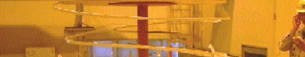
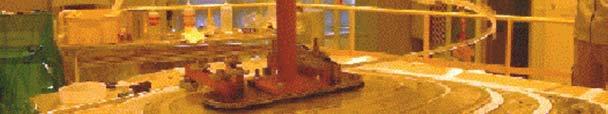
2 4.2 Superconducting sector magnet Outline Cross-sectional and plan views of the sector magnet are shown in Fig The sector magnet is 7.2 m in length and 6 m in height. The weight is about 800 t per each. The sector angle is 25 deg. The maximum sector field is 3.8 T, which is required to accelerate U 88+ ions at 350 MeV/nucleon. Main components of the sector magnet are: a pair of superconducting main coils, four sets of superconducting trim coils, their cryostat, thermal insulation support links, twenty-two pairs of normal conducting trim coils, warm-poles and a yoke. Figs and show a cross section of these components and a bird s-eye view of their assembly, respectively. A photograph of the whole sector magnets assembled in the SRC vault is shown in Fig Superconductor The superconductor that is used for the superconducting main and trim coils has a rectangular shape consisting of a Rutherford-type Nb-Ti cable located at the center of conductor and a stabilizer housing. The conductors cross-sectional area measures 8 mm by 15 mm. The stabilizer material is Al-alloy with 1,000 ppm Ni, which gives a high 0.2 %-yield strength of about 55 MPa at room temperature. The residual resistivity ratio is greater than The cable is composed of ten strands of 1.18 mm in diameter, each being composed of about 960 filaments of 28 mm in diameter. The Cu/Nb-Ti ratio, the residual resistivity ratio of Cu stabilizer and the critical currents of the strand are 0.84, 100 and >16,000 A (5 T), >13,000 A (6 T) and >9,500 A (7 T) at 4.3 K, respectively. The conductor s cross section is shown in Fig Main Coil A solenoid winding with a total turn number of 396 (22x18 in the horizontal and vertical directions, respectively) is adopted for the main coil with cooling gaps of 0.8 mm and 1.5 mm horizontally and vertically, respectively. The maximum current of the main coil is 5,000 A, giving the maximum magneto-motive force per sector of 4.0 MA. Cross-sectional area of the coil measures 208 mm by 284 mm. The maximum current density is 34 A/mm 2. The main coil is designed based on Maddock s partial stabilization criterion. Cryogenic stabilized current at 6 T estimated from the measured resistivity and heat flux is greater than 6,000 A, which has been confirmed by the test using a small model coil. Operational point of the main coil is shown in Fig along with that of the trim coil. The maximum total stored energy of the 2
3 main coils is 235 MJ. The main coil vessel, the cross section of which is shown in Fig , is made of stainless steel; its thickness is 50 or 60 mm. The C-shaped vessel is made first, and then the coil winding is performed with a tension stress of 20 MPa. Next, the outer plate is attached with screws made of high-strength stainless steel (A286), and finally thin seal covers with an L-shaped cross section are welded to the vessel. Pre-stress to the coil is applied at a pressure of 10 MPa with a wedge and the outer plate vertically and horizontally, respectively. The vessel is designed in such a way that there is no straight section for the coil winding. The horizontal electromagnetic force of about 2.6 MN/m is exerted on the long section of the vessel covering the beam acceleration area. In order to sustain this force, a pair of connecting plates is attached to the both sides of this section. The plate is 1 m in width and 25 mm in thickness. One of these plates crosses through the rectangular hole (1.5 m in width and 160 mm in height) of the warm iron pole. The maximum deformation of the vessel is 1.8 mm. Fabrication of the coil vessel, coil winding and welding of the seal covers were conducted with an accuracy of 0.2 mm, 0.6 mm and 0.2 mm, respectively. Figs and show photographs of the coil winding and the welding of the L-shaped seal covers, respectively. Trim coil Superconducting trim coils consist of four sets (parameters) as shown in Fig A double-pancake winding is adopted, in which the coils are indirectly cooled by forced twophase helium through tubes engraved on the coil case as shown in Fig The maximum current is 3,000 A. The coil case is made of two Al-alloy plates that sandwich the trim coils. The LHe cooling tubes are arranged with a pitch of 300 mm. The heat-transfer coefficient measured with a model is over 50 Ω/m 2 /K. Operational point of the trim coil is shown in Fig A photograph of the winding of the trim coils is shown in Fig The coil case is divided into two parts, each containing two of the four sets. The calculated maximum deformation of the case due to electromagnetic forces is about 1 mm. These coil cases are attached to the main coil vessel with screws. Twenty-two pairs of normal-conducting trim coils are attached on the surface of the beam chamber. The maximum currents of the trim coils are 600, 800 and 1,200 A according to the region where they are placed. The coil is made of a double-tube consisting of a copper conductor of 10 mm in diameter covered with a stainless steel of 17 mm in diameter with an insulator in between. 3
4 Power supply The power supplies of the main coils are composed of one main power supply with a maximum current of 5,200 A and six auxiliaries with that of 100 A which are used to adjust differences of magnetic fields among the sector magnets. The power supplies of the trim coils are composed of four main power supplies with the maximum current of 3,200 A, two auxiliaries with that of 400 A, and six auxiliaries with that of 100 A. The stability of the main power supplies for the main and trim coils is within 10 ppm per 8 h. In order to protect the superconducting main and trim coils, the quench characteristics were calculated in terms of current decay, temperature rise, and voltage development. The simulation shows that the optimal resistance of the dump resistor should be 0.3 Ω and 0.05 Ω for the main coil and the trim coil, respectively. The temperature of the main coil rises up to about 140 K. The maximum voltage applied between the main coil and the coil vessel can be half of 1,500 V, by taking the earth at the middle point of the dump resistor. The time constant of the main coil is thus 60 s (the self-inductance of the main coil is 18.8 H). The dump resistor is made of steel with a weight of 2 t and is air-cooled. Thermal shield The 4.5 K cold masses are covered with a total area of 110 m 2 (per sector magnet) of 70 K thermal radiation shields. The thermal shields are composed of stainless steel plates of 3 mm in thickness and multi-layer insulators. GHe cooling tubes are attached to the surfaces of the plates. For the multi-layer insulators, two types are used according to the radiation environment: one is polyimide sheets that are vacuum-evaporated with Al on both sides, and the other polyester sheets. The former is used for a quarter of their total areas that would be exposed to high radiation. Cryostat Conceptual drawing of the cryostat, beam chamber and normal-conducting trim coils is shown in Fig ; a photograph of them is shown in Fig The side walls of the cryostat are made of stainless steel. The upper and lower walls, which constitute part of a pole, are made of steel. The side walls and the upper and lower walls are welded to each other. The maximum deformation of the walls due to atmospheric pressure is 5 mm. The beam chamber, which constitutes part of the cryostat, is made of stainless steel. The gap aperture of the chamber is 90 mm in which the injection and extraction elements are placed. 4
5 Thermal-insulation support The cold mass is supported with a total of 17 thermal-insulation support links as shown in Fig A multi-cylinder type of support link used for the radial support is designed to sustain the radial shifting force of 90 kn. It is fixed on the surface of the back yoke. The vertical and azimuthal supports are made of titanium-alloy rod. The structural analysis shows that the minimum natural frequency (22 Hz) is larger than 20 Hz, which is adopted as the threshold value for reactors in Japan. The entire system of support links is thus designed to sustain the additional force due to an earthquake of 980 Gal and 490 Gal in the horizontal and vertical directions, respectively. Pole and yoke The pole is divided into two pieces in order to make a hole through which the connecting plate of the main coil vessel passes, as shown in Fig The slabs of the upper and lower yokes are stacked in the horizontal direction in order to keep the deformation due to electromagnetic forces as small as possible. The typical slab is 5.7 m (length) x 0.3 m (thickness) x 2.2 m (width). The weight of the yoke per sector is about 750 t. The carbon content of the pure iron is less than 0.01 %. Magnetic shield For magnetic shielding, iron slabs are bridged on the top and bottom pf the valley regions between the neighboring sector magnets. Other slabs are placed vertically between these top and bottom slabs and between the back yokes of the sector magnets. Cross-sectional and plan views of the magnetic shield are shown in Fig The vertical outside slabs are assembled to form a double-leafed hinged door to be opened when the maintenance is carried out for the rf resonators, vacuum pumps and so on in the valley region. Instrumentation A total of about 350 temperature sensors and 430 strain gauges are mounted at the periphery of the cold mass. They have a possibility of being exposed to high radiation doses. Therefore, radiation effects on the cryogenic temperature sensors such as Cernox TM, Carbonglass TM resistor (CGR) and PtCo were tested using 210 MeV prton beams from the RRC. 5
6 Cryogenic cooling system The cryogenic cooling system is a closed-circuit system without liquid nitrogen; it consists of a control Dewar vessel connected to the six cryostats of the sector magnets and the cryostat of the SBM, a refrigerator, three compressors and four reservoir tanks for GHe. Figure shows photographs of the refrigerator, the compressors and the buffer tanks. The control Dewar vessel is located on the top of the six sector magnets. The outer cryostat vessel of the control Dewar measures 2.5 m in diameter by 3.7 m in height; the volume of the helium vessel is about 2300 L, in which about 1700 L of LHe is stored. The connection of the main and trim coils among the six sector magnets is made inside the Dewar (see Fig ), and all of six types of current leads for the coils are set on the top of the Dewar. The total heat load is 350 W at 4.5 K: 295 W for the sector magnets, 10 W for the control Dewar vessel and 45 W for the transfer tubes. The refrigerator has a cooling power of 620 W at 4.5 K for the coils, 4000 W at 70 K for the thermal radiation shields, 4 g/s for the current leads. The total equivalent refrigeration capacity at 4.5 K is approximately 1,100 W, which was confirmed by the recent test on the refrigerator. The refrigerator is of TCF200S type of LINDE. Each of the three compressors (one is a spare) has an electric power of 315 kw and a gas flow rate of 74 g/s. Each of the four reservoir tanks has a volume of 100 m 3 ; its size is 15 m in height and 3 m in diameter. The designed pressure of the tank is 2 MPa. One of the four reservoir tanks is used as a buffer tank in regular operation, and the other three are used to recover evaporated helium as through a recovery tube line when the coils quench. It is estimated that it takes 21 days to cool a total of 140 t of the cold masses from room temperature to 4.5 K with this system. Change of the floor level The floor level of the SRC vault has been monitored as shown in Fig to see how much the floor sunk due to such heavy weight as 8300 t. The data suggests that the floor around the north and east wall sank by 2 mm after the installation of the parts of the SRC, and then they stayed there for several months. The lower yoke level was re-adjusted after this measurement. The yoke levels were measured again two months later, suggesting that the upper surface of the lower yokes was tilted by 0.5 mm in 20 m. However, we judge that this tilt is not harmful to the performance of the SRC. We plan to continue the monitoring. 6
7 Cool-down test The assembly of the sector magnets was completed in September The cool-down started on September 19. The temperature of the sector magnets has been decreased smoothly by keeping the temperature difference between the inlet and outlet of the coil vessels as well as between the upper and lower parts less than 50 K and 20 K, respectively. On October 13, the resistance of the coils became zero (superconducting), which means that the temperature at that time was less than 10 K. As of October 15, the temperature of the main coil and trim coil has reached around 4.5 K and the total volume of them is filled with liquid He. The excitation test of the sector magnets is scheduled for a week from around October 20, after which the magnetic field mapping will be carried out for about three months. Figures show a schematic diagram for the cool-down, trend graphs of the temperature, the pressure of the cryostat vacuum chamber and the resistance of the coil, respectively. 7
 and plan (upper")
8 Figure Cross-sectional (lower figure) and plan (upper figure) views of the sector magnet. 8


9 Figure Cross-sectional view of the main coil, trim coil, pole, yoke and others. Figure Bird s eye view of the sector magnet assembly except for the back yoke. 9


10 Figure a. Photograph of the completed sector magnets in the SRC vault. Figure b. Same as for Fig a. 10


11 Figure Cross section of the superconductor. Figure Operational points of the main and trim coils. 11


12 Figure Cross section of the main coil vessel. Figure Photograph of the main coil winding. Vertical GFRP spacers can be seen. 12


13 Figure Photograph of the welding of the L-shaped seal covers. Figure Plan view of the superconducting trim coils. 13


14 Figure Cross-sectional view of the superconducting trim coil. Figure Photograph of the rim coil winding. 14


15 Figure Conceptual drawing of the cryostat, beam chamber and normalconducting trim coils. Figure Photograph of the cryostat and beam chamber. Some normalconducting trim coils can be seen on the surface of the beam chamber. 15


16 Figure Thermal insulation supports. Figure Cross-sectional view of the pole, connecting plate and thermal insulation supports. 16

17 Figure Cross-sectional and plan views of the magnetic shield. 17
18 Figure Cryogenic cooling system. 18

19 Figure Photograph of the inside of the control Dewar. The main and trim coils for the six sector magnets are connected here in series. A heat transfer device consisting of four turns of tubes to produce two-phase helium for the trim coils can be seen on the inner surface of the vessel Figure Subsidence of the floor level in the SRC. Periods 1, 2, and 3 indicate the following. 1: Delivery of slabs for the yoke and the shield into the SRC and Big-RIPS vaults, 2: Assembly of the lower yokes and 3: Transfer of most slabs from the Big-RIPS vaults into the SRC vaults. 19

20 Figure Schematic diagram for the cool-down of the sector magnet. Figure Trend graph of the temperature during the cool-down. 20
21 Figure Trend graph of the pressure in the cryostat chamber. Figure Trend graph of the resistance of the coil. The resistance drops to zero on October 13 at around 1:30. 21
22 4.3 SBM Outline The superconducting bending magnet (SBM) is used as one of the beam injection elements. It guides beams into the sector magnet. The main parameters of the SBM are listed in Table It needs to generate a magnetic field of 3.8 T along the beam trajectory that has a curvature of 1.2 m. Structure Figure shows a cross-sectional and plan views of the SBM. The SBM consists mainly of coil, iron pole and yoke. Flat coils are adopted for the coils since they can be wound and supported easily. The iron pole is cold and used as the mandrel for the coil winding. The yoke is divided into two parts: cold yoke and warm yoke. The cold yoke is of an H-type. This configuration makes shifting forces and unbalanced forces on the cold mass small. The weight of the cold mass is about 3 t. The two coil casings including the cold poles are attached to the cold yoke. A C-type design is adopted for the warm yoke because the available space in the side of the sector magnet is very limited. A warm duct for ion beams is installed in the gap of the poles. Iron shims and water-cooled baffle slits are attached to the duct. The cold mass of the SBM is installed in the vacuum vessel made of structural iron of 20 mm thickness. It works as a part of the yoke, which makes shifting and unbalanced forces small. The beam tube is connected to the vessel at its ends. The cold mass is supported by three types of thermal insulation supports from room temperature as shown in Fig They were designed to support the cold mass stably against the shifting and unbalanced force as well as against an earthquake of as big as 980 Gal and 490 Gal in the horizontal and vertical direction, respectively. Two-dimensional analysis was carried out to optimize the geometry of the coils, yokes and iron shims. Magnetic forces on the cold mass were calculated for the mechanical design. The geometry of the yokes is optimized so that shifting forces and unbalanced forces on the cold mass are minimized. Three-dimensional field analysis was carried out to study the maximum fields at the coil end and the effective field lengths. Coupling of the field of the SBM with those from the sector magnets is studied using a model that includes the SBM and two sector magnets. The generated field of the SBM decreases by 5 % compared to the standalone excitation. 22
23 Superconductor, coil winding and fabrication Rectangular monolithic NbTi wire of 0.8 mm x 2.4 mm in size was adopted for easier winding. The conductor is coated with polyimide of 50 µm in thickness for electrical insulation. Polyimide was adopted because of its strength against radiation. The operation point is less than 30 % of the critical current. The overall current density of the coil to achieve the required field is about 150 A/mm 2. This value of current density was selected from the experience of the test coil. Coil winding is one of the key issues for the fabrication of the SBM because the coils of the SBM have negative curvature, which is impossible to wind with any tension. The winding method shown in Fig was adopted. In the first step the coil is wound with a tension in a shape that has no negative curvature. The circumference of the coil is taken to be the same as that of the final shape of the SBM coil. After winding of a few layers, the layers are pushed to the mandrel to make the proper shape of the coil. The merit of this method is that the time for winding can be saved without the decrease in performance. This method was successfully applied to the real coil production. After completion of the winding, the coil is impregnated in the vacuum vessel. Figure shows the completed coil. The coil casing is partially covered by seal covers for He tightness. Difference of the real coil shape from the designed one was less than 1 mm, which is allowable to keep the flattness of the field along the trajectory. After the installation of the coils, pre-stresses are applied on the coils by about two hundred set bolts. Figure shows the process of the assembling of the cold mass and piping. The SBM assembled with the control Dewar is shown in Figure Cryogenic cooling system Total heat leaks to the cryostat are estimated to be about 56 W at 80 K, about 15 W at 4.5 K and 1.7 l/h for the current leads. Gas helium for the thermal shield and 4.5 K liquid helium for the coil cooling are supplied to the SBM cryostat by the big refrigeration system of the sector magnets. The current leads are installed in the He reservoir placed near the SBM magnet. Cooling of the SBM without the reservoir for the sector magnet is also possible by replacing it with a conventional liquid He Dewar. Coil protection A quench protection system is installed to dump the current safely. A dump resistance of 2.5 Ω is connected in parallel to the coil. The maximum temperature in the coil is estimated to be about 270 K from the hot spot model and maximum voltage on the coil is about 450 V 23
24 because the resistor is terminated to the ground in the middle of it. Cool-down and excitation test The cool-down test of the SBM was carried out in stand-alone immediately after it was completed in August Figure shows the trend of the coil temperature during the test. It took about 100 hours to cool the cold mass of about 3 t down from the room temperature to 4.3 K. The coolant was changed from liquid nitrogen to gas helium at about 110 K in order to prevent liquid nitrogen from remaining in the coil vessels. Figure shows the excitation curve obtained together with the history of quenches. The magnet reached the designed field after the first quench, which occurred at 315 A. Training effects were clearly observed. Magnetic fields along the beam trajectory were also measured to get effective lengths and field uniformity at various excitation levels. The measured effective length agrees with the designed value, though it differs by about 1.6 % for some excitation levels. 24
25 Table Main parameters of the SBM. Item Value Type Flat coil, Iron pole Iron Yoke (Cold and Warm) Required field A Maximum field in 4.2 T the coil Stored Energy 0.56 MJ Homogeneity few x 10-3 Beam bore 40 (H) x 30 (V) mm 2 Radius mm (Room temperature) Angle degree Coil cross section 55 x 58 mm 2 25
 and cross sectional view (b) of the SBM.")
26 Figure Plan view (a) and cross sectional view (b) of the SBM. Figure Concept of the coil winding. 26


27 Figure Photograph of the completed coil. Figure Assembling of the cold mass. 27

28 Figure Photograph of the completed SBM. Figure Trend graph of the coil temperature during the col-down. 28

29 Figure Excitation curve obtained together with the history of quenches. 29
Physical Design of Superconducting Magnet for ADS Injection I
 Submitted to Chinese Physics C' Physical Design of Superconducting Magnet for ADS Injection I PENG Quan-ling( 彭全岭 ), WANG Bing( 王冰 ), CHEN Yuan( 陈沅 ) YANG Xiang-chen( 杨向臣 ) Institute of High Energy Physics,
SPECIFICATIONS FOR A 4.7 TESLA/310MM BORE ACTIVELY SHIELDED MAGNET SYSTEM
 SPECIFICATIONS FOR A 4.7 TESLA/310MM BORE ACTIVELY SHIELDED MAGNET SYSTEM Prepared by:- Magnex Scientific Limited The Magnet Technology Centre 6 Mead Road Oxford Industrial Park Yarnton, Oxford OX5 1QU,
2.3 PF System. WU Weiyue PF5 PF PF1
 2.3 PF System WU Weiyue 2.3.1 Introduction The poloidal field (PF) system consists of fourteen superconducting coils, including 6 pieces of central selenoid coils, 4 pieces of divertor coils and 4 pieces
DEVELOPMENT OF A BETA 0.12, 88 MHZ, QUARTER WAVE RESONATOR AND ITS CRYOMODULE FOR THE SPIRAL2 PROJECT
 DEVELOPMENT OF A BETA 0.12, 88 MHZ, QUARTER WAVE RESONATOR AND ITS CRYOMODULE FOR THE SPIRAL2 PROJECT G. Olry, J-L. Biarrotte, S. Blivet, S. Bousson, C. Commeaux, C. Joly, T. Junquera, J. Lesrel, E. Roy,
The Results of the KSTAR Superconducting Coil Test
 K orea S uperconducting T okamak A dvanced R esearch The Results of the KSTAR Superconducting Coil Test Nov. 5 2004 Presented by Yeong-KooK Oh Y. K. Oh, Y. Chu, S. Lee, S. J. Lee, S. Baek, J. S. Kim, K.
SPECIFICATION FOR A 7.0 TESLA/400MM ROOM TEMPERATURE BORE MAGNET SYSTEM
 SPECIFICATION FOR A 7.0 TESLA/400MM ROOM TEMPERATURE BORE MAGNET SYSTEM Prepared by:- Magnex Scientific Limited The Magnet Technology Centre 6 Mead Road Oxford Industrial Park Yarnton, Oxford OX5 1QU,
STATUS OF THE KOLKATA K500 SUPERCONDUCTING CYCLOTRON
 STATUS OF THE KOLKATA K500 SUPERCONDUCTING CYCLOTRON Rakesh K. Bhandari (for VECC Staff) Variable Energy Cyclotron Centre, Department of Atomic Energy, Kolkata 700 064, India Abstract A superconducting
STATUS OF THE SUPERCONDUCTING CYCLOTRON PROJECT AT VECC
 STATUS OF THE SUPERCONDUCTING CYCLOTRON PROJECT AT VECC Bikash Sinha and R. K. Bhandari Variable Energy Cyclotron Centre, Department of Atomic Energy, Kolkata 700 064, India Abstract A superconducting
SPECIFICATIONS FOR AN MRBR 7.0 TESLA / 210MM ACTIVELY SHIELDED MAGNET SYSTEM
 SPECIFICATIONS FOR AN MRBR 7.0 TESLA / 210MM ACTIVELY SHIELDED MAGNET SYSTEM Prepared by:- Magnex Scientific Limited The Magnet Technology Centre 6 Mead Road Oxford Industrial Park Yarnton, Oxford OX5
TECHNICAL SPECIFICATIONS. FOR AN MRBR 7.0 TESLA / 160mm ACTIVELY SHIELDED ROOM TEMPERATURE BORE MAGNET SYSTEM
 TECHNICAL SPECIFICATIONS FOR AN MRBR 7.0 TESLA / 160mm ACTIVELY SHIELDED ROOM TEMPERATURE BORE MAGNET SYSTEM Prepared by:- Magnex Scientific Limited The Magnet Technology Centre 6 Mead Road Oxford Industrial
PRELIMINARY SPECIFICATIONS MRBR 7.0 TESLA / 210MM ACTIVELY SHIELDED CRYO-COOLED MAGNET SYSTEM
 PRELIMINARY SPECIFICATIONS MRBR 7.0 TESLA / 210MM ACTIVELY SHIELDED CRYO-COOLED MAGNET SYSTEM Prepared by:- Magnex Scientific Limited The Magnet Technology Centre 6 Mead Road Oxford Industrial Park Yarnton,
Magnets Y.C. Saxena Institute for Plasma Research. 1/16/2007 IPR Peer Review Jan
 Magnets Y.C. Saxena Institute for Plasma Research 1/16/2007 IPR Peer Review 15-17 Jan 2007 1 Magnet Development Program driven by Laboratory Scale Experiments ADITYA Tokamak SST-1 Tokamak 1/16/2007 IPR
Testing of the Toroidal Field Model Coil (TFMC)
") 1 CT/P 14 Testing of the Toroidal Field Model Coil (TFMC) E. Salpietro on behalf of the ITER-TFMC Team EFDA-CSU, Garching,, Germany ettore.salpietro@tech.efda.org Abstract The paper shortly describes the
1 CT/P 14 Testing of the Toroidal Field Model Coil (TFMC) E. Salpietro on behalf of the ITER-TFMC Team EFDA-CSU, Garching,, Germany ettore.salpietro@tech.efda.org Abstract The paper shortly describes the
Cryogenic Testing of Superconducting Corrector Magnets for the LHC Main Dipole
 Cryogenic Testing of Superconducting Corrector Magnets for the LHC Main Dipole A.M. Puntambekar SC Tech Lab, AAMD Div. Raja Ramanna Centre For Advanced Technology, Indore Workshop on Cryogenic Science
HIGH MAGNETIC FIELD SUPERCONDUCTING MAGNETS FABRICATED IN BUDKER INP FOR SR GENERATION
 HIGH MAGNETIC FIELD SUPERCONDUCTING MAGNETS FABRICATED IN BUDKER INP FOR SR GENERATION K.V. Zolotarev *, A.M. Batrakov, S.V. Khruschev, G.N. Kulipanov, V.H. Lev, N.A. Mezentsev, E.G. Miginsky, V.A. Shkaruba,
TESLA Quad Package With BPM
 TESLA Quad Package With BPM H. Brueck, DESY Zeuthen, January 22, 2004 Technology Working Group 1 Topics The TESLA Quadrupole Package Status of Components Magnet Feedthroughs HTc Leads BPM Test in ACC6
Brett Parker, representing the
 Compact Superconducting Magnet Solution for the 20 mr Crossing Angle Final Focus Brett Parker, representing the Brookhaven Superconducting Magnet Division Message: Progress continues on the compact superconducting
HTS PARTIAL CORE TRANSFORMER- FAULT CURRENT LIMITER
 EEA CONFERENCE & EXHIBITION 2013, 19-21 JUNE, AUCKLAND HTS PARTIAL CORE TRANSFORMER- FAULT CURRENT LIMITER JIT KUMAR SHAM*, UNIVERSITY OF CANTERBURY, CHRISTCHURCH, NEW ZEALAND PROF. PAT BODGER, UNIVERSITY
Superconducting Magnets theory and design. Guillaume Donnier-Valentin
 Superconducting Magnets theory and design Guillaume Donnier-Valentin Cryocourse September 2011 1 Superconducting wire Critical parameters Critical temperature Critical magnetic field Critical current density
Figure 1. TAMU1 dipole cross-section. Figure 2. Completed TAMU1 dipole and group that built it.
 Testing of TAMU1 Dipole Team that built it: C. Battle, R. Blackburn, N. Diaczenko, T. Elliott, R. Gaedke, W. Henchel, E. Hill, M. Johnson, H. Kautzky, J. McIntyre, P. McIntyre, A. Sattarov Team that tested
Residual Resistivity Ratio (RRR) Measurements of LHC Superconducting NbTi Cable Strands
 Measurements of LHC Superconducting NbTi Cable Strands") EUROPEAN ORGANIZATION FOR NUCLEAR RESEARCH European Laboratory for Particle Physics Large Hadron Collider Project LHC Project Report 896 Residual Resistivity Ratio (RRR) Measurements of LHC Superconducting
EUROPEAN ORGANIZATION FOR NUCLEAR RESEARCH European Laboratory for Particle Physics Large Hadron Collider Project LHC Project Report 896 Residual Resistivity Ratio (RRR) Measurements of LHC Superconducting
High Voltage Instrumentation Cables for the ITER Superconducting Magnet Systems
 High Voltage Instrumentation Cables for the ITER Superconducting Magnet Systems Summary for Call for Nominations 1. Background and scope ITER will be the world's largest experimental facility to demonstrate
COIL WINDING ISSUES P. Fabbricatore INFN Genova LCD - Magnet 13Oct09. Coil winding issues
 Coil winding issues Based on experience acquired with CMS coil construction, some preliminary considerations about the envisaged winding (and in general manufacturing) issues of a large superconducting
RF STATUS OF SUPERCONDUCTING MODULE DEVELOPMENT SUITABLE FOR CW OPERATION: ELBE CRYOSTATS
 RF STATUS OF SUPERCONDUCTING MODULE DEVELOPMENT SUITABLE FOR CW OPERATION: ELBE CRYOSTATS J. Teichert, A. Büchner, H. Büttig, F. Gabriel, P. Michel, K. Möller, U. Lehnert, Ch. Schneider, J. Stephan, A.
THE CRYOGENIC SYSTEM OF TESLA
 THE CRYOGENIC SYSTEM OF TESLA S. Wolff, DESY, Notkestr. 85, 22607 Hamburg, Germany for the TESLA collaboration Abstract TESLA, a 33 km long 500 GeV centre-of-mass energy superconducting linear collider
Use of inductive heating for superconducting magnet protection*
 PSFC/JA-11-26 Use of inductive heating for superconducting magnet protection* L. Bromberg, J. V. Minervini, J.H. Schultz, T. Antaya and L. Myatt** MIT Plasma Science and Fusion Center November 4, 2011
Insertion Devices Lecture 4 Undulator Magnet Designs. Jim Clarke ASTeC Daresbury Laboratory
 Insertion Devices Lecture 4 Undulator Magnet Designs Jim Clarke ASTeC Daresbury Laboratory Hybrid Insertion Devices Inclusion of Iron Simple hybrid example Top Array e - Bottom Array 2 Lines of Magnetic
Final Publishable Summary
 Final Publishable Summary Task Manager: Dr. Piotr Klimczyk Project Coordinator: Mr. Stefan Siebert Dr. Brockhaus Messtechnik GmbH & Co. KG Gustav-Adolf-Str. 4 D-58507 Lüdenscheid +49 (0)2351 3644-0 +49
CONSTRUCTION AND TESTING OF ARC DIPOLES AND QUADRUPOLES FOR THE RELATIVISTIC HEAVY ION COLLIDER (RHIC) AT BNL *
 AT BNL *") 996 IEEE. Personal use of this material is permitted. However, permission to reprint/republish this material for advertising or promotional purposes or for creating new collective works for resale or redistribution
996 IEEE. Personal use of this material is permitted. However, permission to reprint/republish this material for advertising or promotional purposes or for creating new collective works for resale or redistribution
MULTIPACTING IN THE CRAB CAVITY
 MULTIPACTING IN TH CRAB CAVITY Y. Morita, K. Hara, K. Hosoyama, A. Kabe, Y. Kojima, H. Nakai, KK, 1-1, Oho, Tsukuba, Ibaraki 3-81, JAPAN Md. M. Rahman, K. Nakanishi, Graduate University for Advanced Studies,
two pairs of dipole steering windings that t inside the quadrupole yoke an RF beam position monitor (BPM) consisting of a pill box RF cavity,
 consisting of a pill box RF cavity,") Chapter 6 Quadrupole Package The quadrupole package is shown in Fig. 6.1. It consists of a superferric quadrupole doublet powered in series enclosed in a stainless steel vessel and cooled by 4 K LHe; two
Chapter 6 Quadrupole Package The quadrupole package is shown in Fig. 6.1. It consists of a superferric quadrupole doublet powered in series enclosed in a stainless steel vessel and cooled by 4 K LHe; two
CHAPTER 7 MAIN MAGNETS IN THE ARCS
 CHAPTER 7 MAIN MAGNETS IN THE ARCS 7.1 OVERVIEW 7.1.1 Superconducting Technology for Accelerator Magnets The Large Hadron Collider relies heavily on superconducting magnets which are at the edge of the
Tuning systems for superconducting cavities at Saclay
 Tuning systems for superconducting cavities at Saclay 1 MACSE: 1990: tuner in LHe bath at 1.8K TTF: 1995 tuner at 1.8K in the insulating vacuum SOLEIL: 1999 tuner at 4 K in the insulating vacuum Super-3HC:
Superconducting Septa and Fast Ramped cos(θ) Magnets
 Magnets") Superconducting Septa and Fast Ramped cos(θ) Magnets K. Sugita, E. Fischer, H. Müller, P. Schnizer Superconducting Magnets and Testing Group, Primary Beams, FAIR@GSI, GSI 23-27 March 2015 FCC Week 2015
Superconducting Septa and Fast Ramped cos(θ) Magnets K. Sugita, E. Fischer, H. Müller, P. Schnizer Superconducting Magnets and Testing Group, Primary Beams, FAIR@GSI, GSI 23-27 March 2015 FCC Week 2015
Liquid Helium Heat Load Within the Cornell Mark II Cryostat
 SRF 990615-07 Liquid Helium Heat Load Within the Cornell Mark II Cryostat E. Chojnacki, S. Belomestnykh, and J. Sears Floyd R. Newman Laboratory of Nuclear Studies Cornell University, Ithaca, New York
Particulate Control O&M Training. APC/PCUG Conference July 12-16, 2009 The Woodlands, TX
 Particulate Control O&M Training APC/PCUG Conference July 12-16, 2009 The Woodlands, TX WPCA Particulate Training Seminar July 11, 2009 ESP Power Supply Choices Slide No 1 Precipitator Power Supplies Conventional
Development of a Vibration Measurement Method for Cryocoolers
 REVTEX 3.1 Released September 2 Development of a Vibration Measurement Method for Cryocoolers Takayuki Tomaru, Toshikazu Suzuki, Tomiyoshi Haruyama, Takakazu Shintomi, Akira Yamamoto High Energy Accelerator
Basic Principles and Operation of Transformer
 Basic Principles and Operation of Transformer CONSTRUCTIONAL ASPECTS Cores In order to enhance core s magnetic properties, it is constructed from an iron and silicon mixture (alloy). The magnetic core
ITER NEWSLINE - Central solenoid fabrication: a photo reportage. 18 Jul, https://www.iter.org/newsline/-/2459
 ITER NEWSLINE - 18 Jul, 2016 https://www.iter.org/newsline/-/2459 Central solenoid fabrication: a photo reportage Central solenoid fabrication: a photo reportage Inside of a purpose-built facility at General
Superconducting Magnets Quench Propagation and Protection
 1 Superconducting Magnets Quench Propagation and Protection Herman ten Kate CERN Accelerator School on Superconductivity for Accelerators, Erice 2013 2 1 Quench Protection, what for? Superconducting coil
Roman Pots. Marco Oriunno SLAC, PPA. M.Oriunno, SLAC
 Roman Pots Marco Oriunno SLAC, PPA The Roman Pot technique 1. The Roman Pot, an historically successful technique for near beam physics: ISR, SPS, TEVATRON, RICH, DESY 2. A CERN in-house technology: ISR,
Packaging of Cryogenic Components
 Packaging of Cryogenic Components William J. Schneider Senior Mechanical Engineer Emeritus November 19-23 2007 1 Packaging of Cryogenic Components Day one Introduction and Overview 2 What is important?
Status of the KSTAR Superconducting Magnet System Development
 Status of the KSTAR Superconducting Magnet System Development K. Kim, H. K. Park, K. R. Park, B. S. Lim, S. I. Lee, Y. Chu, W. H. Chung, Y. K. Oh, S. H. Baek, S. J. Lee, H. Yonekawa, J. S. Kim, C. S. Kim,
Vibration studies of a superconducting accelerating
 Vibration studies of a superconducting accelerating module at room temperature and at 4.5 K Ramila Amirikas, Alessandro Bertolini, Wilhelm Bialowons Vibration studies on a Type III cryomodule at room temperature
Tutorial: designing a converging-beam electron gun and focusing solenoid with Trak and PerMag
 Tutorial: designing a converging-beam electron gun and focusing solenoid with Trak and PerMag Stanley Humphries, Copyright 2012 Field Precision PO Box 13595, Albuquerque, NM 87192 U.S.A. Telephone: +1-505-220-3975
Chapter 3. Experimental set up. 3.1 General
 Chapter 3 Experimental set up 3.1 General Experimental set up and various swirl flow generators such as full length twisted tapes, increasing and decreasing order of twist ratio sets and full length screw
Cryogenic Operations at SLAC
 Cryogenic Operations at SLAC J. G. Weisend II, A. Candia, W.W. Craddock, E. Thompson CryoOps 2006 5/30/2006 J. G. Weisend II 1 What Do We Do? Cryogenics at SLAC involve: Large scale He refrigerator operation
KSTAR Construction and Commissioning
 KSTAR Construction and Commissioning H. L. Yang, J. S. Bak, Y. S. Kim, Y. K. Oh, I. S. Whang, Y. S. Bae, Y. M. Park, K. W. Cho, Y. J. Kim, K. R. Park, W. C. Kim, M. K. Park, T. H. Ha and the KSTAR Team
HIGH POWER INPUT COUPLERS FOR THE STF BASELINE CAVITY SYSTEM AT KEK
 HIGH POWER INPUT COUPLERS FOR THE STF BASELINE CAVITY SYSTEM AT KEK E. Kako #, H. Hayano, S. Noguchi, T. Shishido, K. Watanabe and Y. Yamamoto KEK, Tsukuba, Ibaraki, 305-0801, Japan Abstract An input coupler,
PROGRESS IN IFMIF HALF WAVE RESONATORS MANUFACTURING AND TEST PREPARATION
 PROGRESS IN IFMIF HALF WAVE RESONATORS MANUFACTURING AND TEST PREPARATION G. Devanz, N. Bazin, G. Disset, H. Dzitko, P. Hardy, H. Jenhani, J. Neyret, O. Piquet, J. Plouin, N. Selami, CEA-Saclay, France
Third Harmonic Superconducting passive cavities in ELETTRA and SLS
 RF superconductivity application to synchrotron radiation light sources Third Harmonic Superconducting passive cavities in ELETTRA and SLS 2 cryomodules (one per machine) with 2 Nb/Cu cavities at 1.5 GHz
The ATLAS Toroid Magnet
 The ATLAS Toroid Magnet SUN Zhihong CEA Saclay DAPNIA/SIS 1 The ATLAS Magnet System The ATLAS Barrel Toroid Mechanical computations on the Barrel Toroid structure Manufacturing and assembly of the Barrel
INSTRUMENTATION AND CONTROL SYSTEM FOR THE INTERNATIONAL ERL CRYOMODULE
 INSTRUMENTATION AND CONTROL SYSTEM FOR THE INTERNATIONAL ERL CRYOMODULE S. M. Pattalwar, R. Bate, G. Cox, P.A. McIntosh and A. Oates, STFC, Daresbury Laboratory, Warrington, UK Abstract ALICE is a prototype
TESLA RF POWER COUPLERS DEVELOPMENT AT DESY.
 TESLA RF POWER COUPLERS DEVELOPMENT AT DESY. Dwersteg B., Kostin D., Lalayan M., Martens C., Möller W.-D., DESY, D-22603 Hamburg, Germany. Abstract Different RF power couplers for the TESLA Test Facility
LHC ARC DIPOLE STATUS REPORT
 LHC ARC DIPOLE STATUS REPORT C.Wyss, CERN, Geneva, Switzerland # Abstract The LHC, a 7 Tev proton collider presently under construction at CERN, requires 1232 superconducting (SC) dipole magnets, featuring
INDUCTORS WITH MAGNETIC FLUX CONTROLLERS FOR NEW INDUCTION BRAZING INSTALLATIONS. Auburn Hills, MI , USA,
 Various Brazing стр. 1 HES 2004 INDUCTORS WITH MAGNETIC FLUX CONTROLLERS FOR NEW INDUCTION BRAZING INSTALLATIONS Dr. V. Nemkov (1) and Dr. V. Vologdin (2) (1) Centre for Induction Technology, Inc., 1388
K band Focal Plane Array: Mechanical and Cryogenic Considerations Steve White,Bob Simon, Mike Stennes February 20, 2008 COLD ELECTRONICS
 K band Focal Plane Array: Mechanical and Cryogenic Considerations Steve White,Bob Simon, Mike Stennes February 20, 2008 CRYOGENICS AND DEWAR DESIGN The dewar outside dimension must be less than the 36
The Superconducting Strand for the CMS Solenoid Conductor
 The Superconducting Strand for the CMS Solenoid Conductor B. Curé, B. Blau, D. Campi, L. F. Goodrich, I. L. Horvath, F. Kircher, R. Liikamaa, J. Seppälä, R. P. Smith, J. Teuho, and L. Vieillard Abstract-
Transformer Winding Design. The Design and Performance of Circular Disc, Helical and Layer Windings for Power Transformer Applications
 The Design and Performance of Circular Disc, Helical and Layer Windings for Power Transformer Applications Minnesota Power Systems Conference November 3 5, 2009 Earl Brown Heritage Center University of
Cryogenics for Large Accelerators
 Cryogenics for Large Accelerators Dr. Sergiy Putselyk Deutsches Elektronen-Synchrotron (DESY) MKS Division Notkestrasse 85 22607 Hamburg (Germany) Phone: +49 40 89983492 Fax: +49 40 89982858 E-Mail: Sergiy.Putselyk@desy.de
Smart Electromagnetic Flowmeter Open channel Flowmeter Detector
 No. SS2-MGN200-0200 MagneW3000 PLUS Smart Electromagnetic Flowmeter Open channel Flowmeter Detector Model NNK150/951 OVERVIEW The MagneW3000 PLUS Electromagnetic Flowmeter is submersible type of flowmeter
IAEA-CN-94/FT/2-2 Test Results on Systems Developed for SST-1 Tokamak
 Test Results on Systems Developed for SST-1 Tokamak D. Bora, and SST-1 TEAM Institute for Plasma Research, Bhat, Gandhinagar 382 428, INDIA e-mail: dbora@ipr.res.in Abstract. Steady state Superconducting
TRANSFORMER TECHNOLOGY GPT
 Core-Form TRANSFORMER TECHNOLOGY GlobalPT Corporation performs research and engineering developments and co-ordination of works of technical partners in the field of technological progress and commercial
2008 JINST 3 S Magnets. Chapter Overview. 3.2 Superconducting cable
 Chapter 3 Magnets 3.1 Overview The Large Hadron Collider relies on superconducting magnets that are at the edge of present technology. Other large superconducting accelerators (Tevatron-FNAL, HERA-DESY
New Superconducting Toroidal Magnet System for IAXO, the International AXion Observatory
 New Superconducting Toroidal Magnet System for IAXO, the International AXion Observatory I. Shilon, A. Dudarev, H. Silva, U. Wagner, and H. H. J. ten Kate European Organization for Nuclear Research (CERN),
Development of Concave and Convex Roll Defect Inspection Technology for Steel Sheets by Magnetic Flux Leakage Testing Method
 19 th World Conference on Non-Destructive Testing 16 Development of Concave and Convex Roll Inspection Technology for Steel Sheets by Magnetic Flux Leakage Testing Method Yasuhiro MATSUFUJI 1, Takahiro
Conceptual Design of Superferric Magnets for PS2
 High Energy High Intensity Hadron Beams EDMS Nr: 871183.v3 Conceptual Design of Superferric Magnets for PS2 L. Bottura, R. Maccaferri, C. Maglioni, V. Parma, G. de Rijk, L. Rossi, W. Scandale, L. Serio,
1. A sinusoidal ac power supply has rms voltage V and supplies rms current I. What is the maximum instantaneous power delivered?
 1. A sinusoidal ac power supply has rms voltage V and supplies rms current I. What is the maximum instantaneous power delivered? A. VI B. VI C. VI D. VI. An alternating current supply of negligible internal
Tests of the Spoke Cavity RF Source and Cryomodules in Uppsala
 FREIA Report 2012/03 October 2012 DEPARTMENT OF PHYSICS AND ASTRONOMY UPPSALA UNIVERSITY Tests of the Spoke Cavity RF Source and Cryomodules in Uppsala ESS TDR Contribution R. Ruber, T. Ekelöf, R.A. Yogi.
MRI SYSTEM COMPONENTS Module One
 MRI SYSTEM COMPONENTS Module One 1 MAIN COMPONENTS Magnet Gradient Coils RF Coils Host Computer / Electronic Support System Operator Console and Display Systems 2 3 4 5 Magnet Components 6 The magnet The
Physics, Technologies and Status of the Wendelstein 7-X Device
 Physics, Technologies and Status of the Wendelstein 7-X Device F. Wagner on behalf of the W7-X team IPP, BI-Greifswald, EURATOM association Stellarators: toroidal devices with external confinement External
CHAPTER 2 ELECTROMAGNETIC FORCE AND DEFORMATION
 18 CHAPTER 2 ELECTROMAGNETIC FORCE AND DEFORMATION 2.1 INTRODUCTION Transformers are subjected to a variety of electrical, mechanical and thermal stresses during normal life time and they fail when these
Multipole Magnets with High Field Uniformity over Full Length for Super Separator Spectrometer
 1 Multipole Magnets with High Field Uniformity over Full Length for Super Separator Spectrometer S. Manikonda, R. Meinke, J. Nolen, V. Prince and G. Stelzer Abstract First few nested superconducting multipole
Recent Progress in the Superconducting RF Program at TRIUMF/ISAC
 Recent Progress in the Superconducting RF Program at TRIUMF/ISAC Abstract R.E. Laxdal, K. Fong, M. Laverty, A. Mitra, R. Poirier, I. Sekachev, V. Zvyagintsev, TRIUMF, Vancouver, BC, V6T2A3, Canada A heavy
Micro-manipulated Cryogenic & Vacuum Probe Systems
 Janis micro-manipulated probe stations are designed for non-destructive electrical testing using DC, RF, and fiber-optic probes. They are useful in a variety of fields including semiconductors, MEMS, superconductivity,
GOVERNMENT COLLEGE OF ENGINEERING, BARGUR
 1. Which of the following is the major consideration to evolve a good design? (a) Cost (b) Durability (c) Compliance with performance criteria as laid down in specifications (d) All of the above 2 impose
5.4 Production of the R.F. Magnetic Field 5.11
 Chapter 5 - Experimental Apparatus 5.1 Introduction 5.1 5.2 Large System 5.1 5.3 The Solenoid 5.'7 5.4 Production of the R.F. Magnetic Field 5.11 5.5 Small System 5. 5.1 5.1 Introduction Details of the
PI piezo Life Time Test Report. A. Bosotti, R. Paparella, F. Puricelli
 PI piezo Life Time Test Report A. Bosotti, R. Paparella, F. Puricelli 1. Introduction...3 1.1. Vacuum...4 1.2. Temperature...4 1.3. Preload...4 1.4. Driving signal...4 2. General features and conceptual
PES & IAS NY Chapter And NY LMAG June 23 rd, 2015
 PES & IAS NY Chapter And NY LMAG June 23 rd, 2015 High Temperature Insulation Systems and their use in Mobile Transformers Myron B. Bell, PE mbell@deltastar.com Delta Star, Inc. June 23 rd 2015 Introduction
Induction heating of internal
 OPTIMAL DESIGN OF INTERNAL INDUCTION COILS The induction heating of internal surfaces is more complicated than heating external ones. The three main types of internal induction coils each has its advantages
Study of Design of Superconducting Magnetic Energy Storage Coil for Power System Applications
 Study of Design of Superconducting Magnetic Energy Storage Coil for Power System Applications Miss. P. L. Dushing Student, M.E (EPS) Government College of Engineering Aurangabad, INDIA Dr. A. G. Thosar
A few results [2,3] obtained with the individual cavities inside their horizontal cryostats are summarized in Table I and a typical Q o
![A few results [2,3] obtained with the individual cavities inside their horizontal cryostats are summarized in Table I and a typical Q o](/thumbs/78/77724292.jpg "A few results [2,3] obtained with the individual cavities inside their horizontal cryostats are summarized in Table I and a typical Q o") Particle Accelerators, 1990, Vol. 29, pp. 47-52 Reprints available directly from the publisher Photocopying permitted by license only 1990 Gordon and Breach, Science Publishers, Inc. Printed in the United
Particle Accelerators, 1990, Vol. 29, pp. 47-52 Reprints available directly from the publisher Photocopying permitted by license only 1990 Gordon and Breach, Science Publishers, Inc. Printed in the United
Magnet technology Insights & recent UHF results
 Magnet technology Insights & recent UHF results Daniel Baumann, Rainer Kümmerle Bruker Biospin AG Switzerland 25. November 2016 Brussels Innovation with Integrity Innovation with Integrity 1 GHz Aeon at
Available online at ScienceDirect. Physics Procedia 81 (2016 )
") Available online at www.sciencedirect.com ScienceDirect Physics Procedia 81 (2016 ) 182 186 28th International Symposium on Superconductivity, ISS 2015, November 16-18, 2015, Tokyo, Japan Construction
Available online at www.sciencedirect.com ScienceDirect Physics Procedia 81 (2016 ) 182 186 28th International Symposium on Superconductivity, ISS 2015, November 16-18, 2015, Tokyo, Japan Construction
HIGH POWER COUPLER FOR THE TESLA TEST FACILITY
 Abstract HIGH POWER COUPLER FOR THE TESLA TEST FACILITY W.-D. Moeller * for the TESLA Collaboration, Deutsches Elektronen-Synchrotron DESY, D-22603 Hamburg, Germany The TeV Energy Superconducting Linear
Design study for JT-60SA ECRF system and the latest results of JT-60U ECRF system
 Japan-Korea : Workshop on Physics of Wave Heating and Current Drive, NFRI, Daejon, Korea, Jan. 14-15, 2008 R F &LHRF& ECRF ICRF JT - 60 JT-60 RF group Japan Atomic Energy Agency Design study for JT-60SA
Large Superconducting Magnet Systems
 Large Superconducting Magnet Systems P. Védrine 1 CEA Saclay, Gif sur Yvette Cedex, France Abstract The increase of energy in accelerators over the past decades has led to the design of superconducting
S. Ghosh On behalf of Linac, IFR, Cryogenics, RF and beam transport group members. Inter University Accelerator Centre New Delhi India
 S. Ghosh On behalf of Linac, IFR, Cryogenics, RF and beam transport group members Inter University Accelerator Centre New Delhi 110067 India Highlights of presentation 1. Introduction to Linear accelerator
KEK ERL CRYOMODULE DEVELOPMENT
 KEK ERL CRYOMODULE DEVELOPMENT H. Sakai*, T. Furuya, E. Kako, S. Noguchi, M. Sato, S. Sakanaka, T. Shishido, T. Takahashi, K. Umemori, K. Watanabe and Y. Yamamoto KEK, 1-1, Oho, Tsukuba, Ibaraki, 305-0801,
QUARTER WAVE COAXIAL LINE CAVITY FOR NEW DELHI LINAC BOOSTER*
 QUARTER WAVE COAXIAL LINE CAVITY FOR NEW DELHI LINAC BOOSTER* P.N. Prakash and A.Roy Nuclear Science Centre, P.O.Box 10502, New Delhi 110 067, INDIA and K.W.Shepard Physics Division, Argonne National Laboratory,
Operation Status of KEK Accelerator Cryogenic Systems
 Operation Status of KEK Accelerator Cryogenic Systems NAKAI Hirotaka, HARA Kazufumi, HONMA Teruya, KOJIMA Yuuji, NAKANISHI Kota and SHIMIZU Hirotaka (KEK, Japan) Outline Overview of KEK cryogenic systems
INSTALLATION MANUAL FORTRESS SERIES
 Guardian Security Structures TEL 1-406-212-2334 EMAIL rg@gssdoors.com WEB www.gssdoors.com FORTRESS SERIES GENERAL INSTALLATION GUIDELINES 1. The door frame is installed using 16 bolt screws 7,5 mm in
Engineering Aspects of Compact Stellarators *
 1 IAEA-CN-94/FT/2-4 Engineering Aspects of Compact Stellarators * B. E. Nelson 1, A. Brooks 2, R. D. Benson 1, L. A. Berry 1, T. G. Brown 2, J. Chrzanowski 2, M. J. Cole 1, F. Dahlgren 2, H. M. Fan 2,
Chapter 9. Magnet System. 9.1 Magnets in the Arc and Straight Sections
 Chapter 9 Magnet System This chapter discusses the parameters and the design of the magnets to use at KEKB. Plans on the magnet power supply systems, magnet installation procedure and alignment strategies
1. Enumerate the most commonly used engineering materials and state some important properties and their engineering applications.
 Code No: R05310305 Set No. 1 III B.Tech I Semester Regular Examinations, November 2008 DESIGN OF MACHINE MEMBERS-I ( Common to Mechanical Engineering and Production Engineering) Time: 3 hours Max Marks:
HTC Technical Manual
 10.04.009 Table of contents 1. General...3. Technical details...3.1. Primary winding...3.. Secondary winding...3.3. Top terminal...3.4. Rotary spark gap...3.5. Safety spark gap...4 3. Measurements...5
Superconducting RF Cavity Performance Degradation after Quenching in Static Magnetic Field
 Superconducting RF Cavity Performance Degradation after Quenching in Static Magnetic Field T. Khabiboulline, D. Sergatskov, I. Terechkine* Fermi National Accelerator Laboratory (FNAL) *MS-316, P.O. Box
Diseño del Criostato del Receptor de Banda Ancha
 Diseño del Criostato del Receptor de Banda Ancha José Manuel Serna, Beatriz Vaquero, Félix Tercero, Samuel López Informe Técnico IT-CDT 2015-18 [Los desarrollos descritos en este informe técnico han sido
Status of JT-60SA Project
 Status of JT-60SA Project P. Barabaschi a, E. DiPietro a, Y. Kamada b, Y. Ikeda b, S. Ishida c, H. Shirai c, and the JT-60SA Team a JT-60SA EU Home Team, Fusion for Energy, Boltzmannstrasse 2, Garching,
Smart Electromagnetic Flowmeter Open channel Flowmeter Detector
 Magne3000 PLUS Smart Electromagnetic Flowmeter Open channel Flowmeter Detector Model NNK150/951 OVERVIE The Magne3000 PLUS Electromagnetic Flowmeter is submersible type of flowmeter mainly used for flow