Figure 1. TAMU1 dipole cross-section. Figure 2. Completed TAMU1 dipole and group that built it.
|
|
|
- Albert Fowler
- 5 years ago
- Views:
Transcription


1 Testing of TAMU1 Dipole Team that built it: C. Battle, R. Blackburn, N. Diaczenko, T. Elliott, R. Gaedke, W. Henchel, E. Hill, M. Johnson, H. Kautzky, J. McIntyre, P. McIntyre, A. Sattarov Team that tested it: P. Bish, T. Elliott, R. Hannaford, A. Lietzke, A. McInturff, P. McIntyre Abstract. The NbTi model dipole TAMU1 was successfully tested at Lawrence Berkeley Lab. The dipole reached 84% of short-sample current on the first quench, and trained rapidly to 96%. Notwithstanding a variety of component failures during fabrication and assembly, the dipole still had sufficient provisions for monitoring and quench firing to permit a fairly extensive study of its performance. The quench heaters were capable of inducing quench in <10 msec. The splice resistance was measured to be 0.28 nω, consistent with excellent splice contact. AC loss properties were studied during ramp studies. Ramps to 1,000 A/s were sustained. The dipole is a success. The superconducting magnet TAMU1 is a NbTi block-coil dipole, designed and built at Texas A&M University. 1. The magnet was built as a learning model, to evaluate construction techniques and materials that will be necessary for subsequent high-field Nb 3 Sn dipoles. The coil was fabricated using the insulation materials (S-glass cloth, mica paper), vacuum impregnation, and provisions for stress management that are being developed for use in a 12 Tesla Nb 3 Sn dipole 2. Figure 1 shows the cross-section of the dipole and its flux return. Its principal parameters are given in Table 1. The coil is asymmetric, built in the geometry that would be needed for a flux-coupled dual-bore dipole. The superconducting cable is SSC inner cable, having the properties given in Table 2. Figure 1. TAMU1 dipole cross-section. Figure 2. Completed TAMU1 dipole and group that built it.
2
3 Table 1. Main parameters of the TAMU1 dipole. Maximum field 6.88 Tesla Maximum current 8.55 ka Inductance 3.5 mh Stored energy 70 kj Overall length 110 cm Body length 50 cm Beam tube diameter 2.5 cm Table 2. Properties of SSC inner cable used in the coil. Strand diameter 0.8 mm j 4.2 K, 5 T 2,846 A/mm 2 Cu/SC ratio 1.3 # strands 30 Cable width mm Cable thickness 1.37 mm Table 3. Properties of the windings. winding Maximum 8.8 T T # turns Self-inductance mh Total mutual inductance mh 1, , , Figure 3. Schematic showing voltage taps (V), splices (S), quench heaters (Q), and spot heater (S). The coil is wound in three double-windings (1,2; 3,4: 5,6 in Figure 3). summarizes the properties of each winding. Each double-winding is wound two-in-hand with an S-transition at the inner boundary. Successive double-windings are connected by a splice (S i ). The windings were instrumented with voltage taps V i, quench heaters Q i, and spot heaters H i. Although all windings were instrumented when the dipole was built, a number of the taps and heaters were damaged in impregnation and preloading so that they were either shorted to ground, open, or internally shorted. The surviving elements were located as indicated in Figure 3, and provided an adequate basis to protect the magnet (with Q 2, Q 4, and Q 5 we were able to force quench in each double-winding), monitor the voltage across each winding, and launch a local quench (spot heater H 4 one turn in from the outside of winding 4). The coil was preloaded within its flux return by a pattern of large bolts visible in Figure 2. Unfortunately the coil attained a horizontal bow of ~2 mm during vacuum impregnation. In order to provide uniform contact along the sides of the coil within the flux return, it was necessary to apply a smart shim of S-glass-reinforced epoxy. As a consequence it was not
4 possible to close the rib/plate structure that was designed to provide stress management, so that the preload of the flux return is delivered directly to the coil. Several intermittent shorts from coil to case were encountered as we delivered preload. We were able to preload to 50 tons, ~30% of the maximum calculated Lorentz stress, without introducing any shorts. We elected to adopt this as a working preload. As the coil is excited to full field, the Lorentz load will exceed the preload and the retaining bolts will stretch according to their elastic modulus the total bolt strain is calculated to be ~200 µm. The resulting coil motion could produce quenches at high field. In preparation for testing, the resistances of all windings were measured to check for turn-toturn shorts. An imbalance equivalent to two turns was observed between V 1 and V 2, which was due to the placement of the voltage tap one turn in from the S-transition between coils 1 and 2. A turn-to-turn short is discovered and removed. The dipole was cooled to 4.5 K, and all windings were checked for turn-to-turn shorts by driving a triangular current waveform through the coil. The rate-of-rise was twice the rate-offall, so that the inductance of each winding could be checked independently at two frequencies. Figure 4 shows the voltage response. The voltages across coils 1 and 2 were observed to be mismatched by a ratio ~1.7, much more than the resistive mismatch ratio of 1.22 from the location of the voltage tap, indicating that there was a turn-to-turn short. The short presumably had high enough resistance that it did not perturb the resistance check at room temperature, but provided a parallel current path in AC response. Such a short could pose a serious hazard in a quench from high-current operation. We decided to attempt to remove it by exercising the coil on a continuous sawtooth ramp to 300 A peak current, and increasing the ramp rate in a succession of steps until the coil quenched from AC heating. The rationale was that a substantial but limited energy would be dumped through the short in an impulse during quench. It was hoped that the impulse would be sufficient to burn out the short without damaging the coil. Figure 5 shows the temperatures measured at the locations T 1, T 7, and T 8 indicated in Figure 3. The Each succeeding plateau region corresponds to a continuous ramp to 300 A, at a succession of increasing ramp rates: 50 A/s, 100 A/s, 200 A/s, 300 A/s, 400 A/s, 500 A/s, and finally 600 A/s. At 600 A/s, the coil temperature reached the critical temperature T c = 9.3 K, and the coil quenched. After recovery, the coil did not quench during a repeated 600 A/s ramp sequence, but did with a 700 A/s ramp sequence. Something in the coil had changed to produce this change in behavior. We then measured the voltages across the windings during a ramp to 300 A with 400 A/s up and 200 A/s down. Figure 6 shows the response. All windings exhibited inductances that were consistent with their calculated inductances L i, indicating that the short had been successfully removed.
5 Figure 4. Voltage response to triangular current ramp (20 A max). Figure 5. Temperature response in coil during current ramp sequence. Figure 6. Voltage response to current ramp after ramp processing.


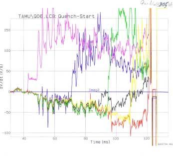
6 Evaluation of quench heater operation We next increased coil current to 2,000 A, and fired current pulses to the three quench heaters Q i, in order to evaluate their effectiveness in initiating quench in the coils that they contacted. Each heater has a room-temperature resistance of ~1.5 Ω, and is situated to face the edge surfaces of all turns of a winding in the end region, as shown in Figure 7. Although two heaters were installed on each of the six windings, only three were operational by the time of testing. Fortunately the three operational heaters were on windings 2, 4, and 5, so that we were able to fire quench in at least one coil of each double-winding. At 2,000 A coil current we fired all three heaters, each with a current pulse of ~50 A for ~30 ms, corresponding to an adiabatic temperature of ~200 K. The voltage response across each coil is shown in Figure 8. On the voltage plot, a positive voltage corresponds to a resistive voltage, while a negative voltage corresponds to an inductive response as the coil current decreases. The three windings with heaters were successfully quenched, while the other three windings remained unquenched for ~100 ms and then quenched. We thus validated that the quench heaters worked successfully. Figure 7. Quench heater: a) foil heater; b) heater installed with S-glass insulation to coil and mica paper insulation to rib. Figure 8. Voltage response following firing of quench heaters (2,000 A coil current).
7 Protection strategy during high-current testing. The magnet was protected by three provisions:! When a voltage pulse was detected across the voltage taps of any coil, signaling a quench, the power supply was immediately phased back so that no further energy was delivered to the magnet;! After a delay of 50 ms, the three quench heaters were fired to initiate quench in all three double-windings;! After a delay of 150 ms, energy was extracted externally by firing a circuit that inserted an external resistor in the coil circuit. Figure 9 shows the timing of the quench heater firings and energy extraction after detection of a quench. The delays were introduced to enable us to identify which coil quenched and to observe the initial development of quench in that and other coils. Q 4 was fired ~10 ms later than Q 2 and Q 5, as indicated in Figure 9 High-current testing of the dipole. We then increased the coil current to measure the maximum field that could be achieved. The current was ramped at 10 A/s. The first quench occurred at a current of 7,200 A, 84% of short-sample current j c = 8,550 A. Figure 10 shows the training history during a sequence of 9 quenches. The dipole attained a reproducible quench current of ~8,020 A, 94% of short-sample. Some of the features of the quench behavior of the TAMU1 dipole are illustrated in Figure 11. Quench 2 appears to have been initiated by a major mechanical motion (the huge spike in all traces). Windings 5 and 6 quenched simultaneously. The other windings remained superconducting until the quench heaters were fired. In Quench 6 also, a mechanical motion excited all windings, and after a delay of ~3 ms winding 3 quenched. Winding 4 then quenched after a delay of ~28 ms, and then the quench heaters initiated quench in windings 2 and 5 In Quench 8, winding 6 quenched first after a fast transient. In the progression of the quench in winding 6, one can see a particularly clear progression of the quench by jump step from turn to turn. The successive voltage spikes occur when the heat from the quenched region on one turn is conducted through the turn-to-turn insulation sufficiently to quench the same region on its neighboring turns. The jump-step time is ~4 ms.
8 Figure 9. Timing of quench heater firings and energy extraction following detection of a quench. TAMU-1 Quench History 8 6 Iq (KA) 4 2 System Training Ramp-Rate Ramp # Figure 10. Training history of TAMU1.

9 Quench 2 Quench 6

10 Quench 8 Figure 11. Voltage response during quench, for three quenches: a) quench 7,650 A; b) quench 8,050 A; quench 8,020 A. Measurement of splice resistance. We measured the voltage across the splice joints at a succession of coil currents, in order to determine the splice resistance. The data on splice S1 is shown in Figure 12. For splice S2, the common-mode noise on the voltage taps was too great to make reliable measurements. On splice S1, there was a thermal gradient offset of ~-1 µv. The measurements were however reproducible and enable an accurate measurement of the slope: R = 0.28 nω. 1 Voltage (µv) nω Current (ka) Figure 12. Measurement of splice resistance for splice S1.
11 Ramp rate studies. We studied AC losses by measuring the quench current as a function of ramp rate. The results are presented in Figure 13. Quench current fell to 50% at a ramp rate of ~1,500 A/s. quench current (ka) di/dt (A/s) Figure 13. Dependence of quench current on ramp rate. Spot heater studies. We pulsed the spot heater H 4 on winding 4, in order to evaluate its operation in initiating a local quench. We excited it with a current pulse of 2 A for 10 ms. This pulse, limited by lead resistance, was adequate, but only barely so, to fire a quench. We will need to re-design the spot heaters for our next dipole. 1 Blackburn et al., 12 Tesla hybrid block-coil dipole for future hadron colliders, Proc. Applied Superconductivity Conf., Virginia Beach, VA Sept , C. Battle et al., Optimized block-coil dipoles for future hadron colliders, Proc. Int'l. Conf. on Magnet Technology, Jacksonville, FL, Sept , 1999.
2.3 PF System. WU Weiyue PF5 PF PF1
 2.3 PF System WU Weiyue 2.3.1 Introduction The poloidal field (PF) system consists of fourteen superconducting coils, including 6 pieces of central selenoid coils, 4 pieces of divertor coils and 4 pieces
Physical Design of Superconducting Magnet for ADS Injection I
 Submitted to Chinese Physics C' Physical Design of Superconducting Magnet for ADS Injection I PENG Quan-ling( 彭全岭 ), WANG Bing( 王冰 ), CHEN Yuan( 陈沅 ) YANG Xiang-chen( 杨向臣 ) Institute of High Energy Physics,
Cryogenic Testing of Superconducting Corrector Magnets for the LHC Main Dipole
 Cryogenic Testing of Superconducting Corrector Magnets for the LHC Main Dipole A.M. Puntambekar SC Tech Lab, AAMD Div. Raja Ramanna Centre For Advanced Technology, Indore Workshop on Cryogenic Science
Magnets Y.C. Saxena Institute for Plasma Research. 1/16/2007 IPR Peer Review Jan
 Magnets Y.C. Saxena Institute for Plasma Research 1/16/2007 IPR Peer Review 15-17 Jan 2007 1 Magnet Development Program driven by Laboratory Scale Experiments ADITYA Tokamak SST-1 Tokamak 1/16/2007 IPR
Residual Resistivity Ratio (RRR) Measurements of LHC Superconducting NbTi Cable Strands
 Measurements of LHC Superconducting NbTi Cable Strands") EUROPEAN ORGANIZATION FOR NUCLEAR RESEARCH European Laboratory for Particle Physics Large Hadron Collider Project LHC Project Report 896 Residual Resistivity Ratio (RRR) Measurements of LHC Superconducting
EUROPEAN ORGANIZATION FOR NUCLEAR RESEARCH European Laboratory for Particle Physics Large Hadron Collider Project LHC Project Report 896 Residual Resistivity Ratio (RRR) Measurements of LHC Superconducting
4. Superconducting sector magnets for the SRC 4.1 Introduction
 4. Superconducting sector magnets for the SRC 4.1 Introduction The key components for the realization for the SRC are: the superconducting sector magnet and the superconducting bending magnet (SBM) for
The Results of the KSTAR Superconducting Coil Test
 K orea S uperconducting T okamak A dvanced R esearch The Results of the KSTAR Superconducting Coil Test Nov. 5 2004 Presented by Yeong-KooK Oh Y. K. Oh, Y. Chu, S. Lee, S. J. Lee, S. Baek, J. S. Kim, K.
A new hybrid protection system for high-field superconducting magnets
 A new hybrid protection system for high-field superconducting magnets Abstract E Ravaioli 1,2, V I Datskov 1, G Kirby 1, H H J ten Kate 1,2, and A P Verweij 1 1 CERN, Geneva, Switzerland 2 University of
Lawrence Berkeley National Laboratory Lawrence Berkeley National Laboratory
 Lawrence Berkeley National Laboratory Lawrence Berkeley National Laboratory Title Magnet R&D for the US LHC Accelerator Research Program (LARP) Permalink https://escholarship.org/uc/item/6zf7j42r Author
Brett Parker, representing the
 Compact Superconducting Magnet Solution for the 20 mr Crossing Angle Final Focus Brett Parker, representing the Brookhaven Superconducting Magnet Division Message: Progress continues on the compact superconducting
TESLA Quad Package With BPM
 TESLA Quad Package With BPM H. Brueck, DESY Zeuthen, January 22, 2004 Technology Working Group 1 Topics The TESLA Quadrupole Package Status of Components Magnet Feedthroughs HTc Leads BPM Test in ACC6
SPECIFICATIONS FOR A 4.7 TESLA/310MM BORE ACTIVELY SHIELDED MAGNET SYSTEM
 SPECIFICATIONS FOR A 4.7 TESLA/310MM BORE ACTIVELY SHIELDED MAGNET SYSTEM Prepared by:- Magnex Scientific Limited The Magnet Technology Centre 6 Mead Road Oxford Industrial Park Yarnton, Oxford OX5 1QU,
Correlation between voltage current relation and current distribution in superconducting cables
 Physica C 401 (2004) 129 134 www.elsevier.com/locate/physc Correlation between voltage current relation and current distribution in superconducting cables A. Kuijper a, *, A.P. Verweij a, H.H.J. ten Kate
28/11/2016 Juan Carlos Perez TE-MSC-MDT Jose Ferradas TE-MSC-MDT
 TE-MSC-MDT 28/11/2016 Juan Carlos Perez Jose Ferradas TE-MSC-MDT TE-MSC-MDT Outline Description and status of the project Project TE3536 at Laboratory 927 Magnet Design and Technology (MDT) Main results
Tutorial: designing a converging-beam electron gun and focusing solenoid with Trak and PerMag
 Tutorial: designing a converging-beam electron gun and focusing solenoid with Trak and PerMag Stanley Humphries, Copyright 2012 Field Precision PO Box 13595, Albuquerque, NM 87192 U.S.A. Telephone: +1-505-220-3975
TECHNICAL SPECIFICATIONS. FOR AN MRBR 7.0 TESLA / 160mm ACTIVELY SHIELDED ROOM TEMPERATURE BORE MAGNET SYSTEM
 TECHNICAL SPECIFICATIONS FOR AN MRBR 7.0 TESLA / 160mm ACTIVELY SHIELDED ROOM TEMPERATURE BORE MAGNET SYSTEM Prepared by:- Magnex Scientific Limited The Magnet Technology Centre 6 Mead Road Oxford Industrial
COIL WINDING ISSUES P. Fabbricatore INFN Genova LCD - Magnet 13Oct09. Coil winding issues
 Coil winding issues Based on experience acquired with CMS coil construction, some preliminary considerations about the envisaged winding (and in general manufacturing) issues of a large superconducting
CONSTRUCTION AND TESTING OF ARC DIPOLES AND QUADRUPOLES FOR THE RELATIVISTIC HEAVY ION COLLIDER (RHIC) AT BNL *
 AT BNL *") 996 IEEE. Personal use of this material is permitted. However, permission to reprint/republish this material for advertising or promotional purposes or for creating new collective works for resale or redistribution
996 IEEE. Personal use of this material is permitted. However, permission to reprint/republish this material for advertising or promotional purposes or for creating new collective works for resale or redistribution
The Superconducting Strand for the CMS Solenoid Conductor
 The Superconducting Strand for the CMS Solenoid Conductor B. Curé, B. Blau, D. Campi, L. F. Goodrich, I. L. Horvath, F. Kircher, R. Liikamaa, J. Seppälä, R. P. Smith, J. Teuho, and L. Vieillard Abstract-
SPECIFICATION FOR A 7.0 TESLA/400MM ROOM TEMPERATURE BORE MAGNET SYSTEM
 SPECIFICATION FOR A 7.0 TESLA/400MM ROOM TEMPERATURE BORE MAGNET SYSTEM Prepared by:- Magnex Scientific Limited The Magnet Technology Centre 6 Mead Road Oxford Industrial Park Yarnton, Oxford OX5 1QU,
Superconducting Magnets Quench Propagation and Protection
 1 Superconducting Magnets Quench Propagation and Protection Herman ten Kate CERN Accelerator School on Superconductivity for Accelerators, Erice 2013 2 1 Quench Protection, what for? Superconducting coil
KSTAR Construction and Commissioning
 KSTAR Construction and Commissioning H. L. Yang, J. S. Bak, Y. S. Kim, Y. K. Oh, I. S. Whang, Y. S. Bae, Y. M. Park, K. W. Cho, Y. J. Kim, K. R. Park, W. C. Kim, M. K. Park, T. H. Ha and the KSTAR Team
HIGH critical current density
 2470 IEEE TRANSACTIONS ON APPLIED SUPERCONDUCTIVITY, VOL. 19, NO. 3, JUNE 2009 Self Field Instability in High-J c Nb 3 Sn Strands With High Copper Residual Resistivity Ratio Bernardo Bordini and Lucio
Name: Lab Partner: Section: The purpose of this lab is to study induction. Faraday s law of induction and Lenz s law will be explored. B = B A (8.
 Chapter 8 Induction - Faraday s Law Name: Lab Partner: Section: 8.1 Purpose The purpose of this lab is to study induction. Faraday s law of induction and Lenz s law will be explored. 8.2 Introduction It
Protection of Hardware: Powering Systems (Power Converter, Normal Conducting, and Superconducting Magnets)
") Protection of Hardware: Powering Systems (Power Converter, Normal Conducting, and Superconducting Magnets) H. Pfeffer, B. Flora, and D. Wolff US Particle Accelerator School, Batavia, IL, USA Abstract Along
Protection of Hardware: Powering Systems (Power Converter, Normal Conducting, and Superconducting Magnets) H. Pfeffer, B. Flora, and D. Wolff US Particle Accelerator School, Batavia, IL, USA Abstract Along
Impulse testing of coils and magnets: present experience and future plans
 Impulse testing of coils and magnets: present experience and future plans M. Marchevsky, E. Ravaioli, LBNL G. Ambrosio, FNAL M. Marchevsky 1 Impulse testing for LARP magnets Impulse testing is a key electrical
PRELIMINARY SPECIFICATIONS MRBR 7.0 TESLA / 210MM ACTIVELY SHIELDED CRYO-COOLED MAGNET SYSTEM
 PRELIMINARY SPECIFICATIONS MRBR 7.0 TESLA / 210MM ACTIVELY SHIELDED CRYO-COOLED MAGNET SYSTEM Prepared by:- Magnex Scientific Limited The Magnet Technology Centre 6 Mead Road Oxford Industrial Park Yarnton,
Magnetics Design. Specification, Performance and Economics
 Magnetics Design Specification, Performance and Economics W H I T E P A P E R MAGNETICS DESIGN SPECIFICATION, PERFORMANCE AND ECONOMICS By Paul Castillo Applications Engineer Datatronics Introduction The
FGJTCFWP"KPUVKVWVG"QH"VGEJPQNQI[" FGRCTVOGPV"QH"GNGEVTKECN"GPIKPGGTKPI" VGG"246"JKIJ"XQNVCIG"GPIKPGGTKPI
 FGJTFWP"KPUKWG"QH"GEJPQNQI[" FGRTOGP"QH"GNGETKEN"GPIKPGGTKPI" GG"46"JKIJ"XQNIG"GPIKPGGTKPI Resonant Transformers: The fig. (b) shows the equivalent circuit of a high voltage testing transformer (shown
CHAPTER 2 ELECTROMAGNETIC FORCE AND DEFORMATION
 18 CHAPTER 2 ELECTROMAGNETIC FORCE AND DEFORMATION 2.1 INTRODUCTION Transformers are subjected to a variety of electrical, mechanical and thermal stresses during normal life time and they fail when these
HIGH MAGNETIC FIELD SUPERCONDUCTING MAGNETS FABRICATED IN BUDKER INP FOR SR GENERATION
 HIGH MAGNETIC FIELD SUPERCONDUCTING MAGNETS FABRICATED IN BUDKER INP FOR SR GENERATION K.V. Zolotarev *, A.M. Batrakov, S.V. Khruschev, G.N. Kulipanov, V.H. Lev, N.A. Mezentsev, E.G. Miginsky, V.A. Shkaruba,
SPECIFICATIONS FOR AN MRBR 7.0 TESLA / 210MM ACTIVELY SHIELDED MAGNET SYSTEM
 SPECIFICATIONS FOR AN MRBR 7.0 TESLA / 210MM ACTIVELY SHIELDED MAGNET SYSTEM Prepared by:- Magnex Scientific Limited The Magnet Technology Centre 6 Mead Road Oxford Industrial Park Yarnton, Oxford OX5
25th SOFT Page 1 of 11
 Experiences from Design and Production of Wendelstein 7-X Magnets K. Riße for the W7-X team Max-Planck Institut für Plasmaphysik, EURATOM Association, Teilinstitut Greifswald, Wendelsteinstraße 1, D 17491
2 Single-mode Diode Laser and Optical Fiber
 A Novel Technique for Minimum Quench Energy Measurements in Superconductors Using a Single-Mode Diode Laser F. Trillaud (a), F. Ayela (b), A. Devred (a),(c), M. Fratini (d), D. Lebœuf (a) and P. Tixador
w Fermi National Accelerator Laboratory
 w Fermi National Accelerator Laboratory FERMILAB-TM-2082 Design Study of 45-mm Bore Dipole for 11 to 12 Tesla Field Magnet Ryuji Yamada and Jonathan Moeller Fermi National Accelerator Laboratory P. 0.
Lumped Network Model of a Resistive Type High T c fault current limiter for transient investigations
 Lumped Network Model of a Resistive Type High T c fault current limiter for transient investigations Ricard Petranovic and Amir M. Miri Universität Karlsruhe, Institut für Elektroenergiesysteme und Hochspannungstechnik,
Update on REBCO accelerator magnet technology development at LBNL and research plan for fusion magnets
 Update on REBCO accelerator magnet technology development at LBNL and research plan for fusion magnets Xiaorong Wang Superconducting Magnet Program, LBNL CCA Workshop, Aspen CO, 9/12/2016 Acknowledgment
Testing of the Toroidal Field Model Coil (TFMC)
") 1 CT/P 14 Testing of the Toroidal Field Model Coil (TFMC) E. Salpietro on behalf of the ITER-TFMC Team EFDA-CSU, Garching,, Germany ettore.salpietro@tech.efda.org Abstract The paper shortly describes the
1 CT/P 14 Testing of the Toroidal Field Model Coil (TFMC) E. Salpietro on behalf of the ITER-TFMC Team EFDA-CSU, Garching,, Germany ettore.salpietro@tech.efda.org Abstract The paper shortly describes the
Use of inductive heating for superconducting magnet protection*
 PSFC/JA-11-26 Use of inductive heating for superconducting magnet protection* L. Bromberg, J. V. Minervini, J.H. Schultz, T. Antaya and L. Myatt** MIT Plasma Science and Fusion Center November 4, 2011
STATUS OF THE KOLKATA K500 SUPERCONDUCTING CYCLOTRON
 STATUS OF THE KOLKATA K500 SUPERCONDUCTING CYCLOTRON Rakesh K. Bhandari (for VECC Staff) Variable Energy Cyclotron Centre, Department of Atomic Energy, Kolkata 700 064, India Abstract A superconducting
Rayleigh Pulse Forming Network. Part II Assessment of sensitivity
 Rayleigh Pulse Forming Network Part II Assessment of sensitivity The pulse forming networks we looked at in Part I of this paper were ideal. The capacitors and inductors did not suffer from any internal
Superconducting Septa and Fast Ramped cos(θ) Magnets
 Magnets") Superconducting Septa and Fast Ramped cos(θ) Magnets K. Sugita, E. Fischer, H. Müller, P. Schnizer Superconducting Magnets and Testing Group, Primary Beams, FAIR@GSI, GSI 23-27 March 2015 FCC Week 2015
Superconducting Septa and Fast Ramped cos(θ) Magnets K. Sugita, E. Fischer, H. Müller, P. Schnizer Superconducting Magnets and Testing Group, Primary Beams, FAIR@GSI, GSI 23-27 March 2015 FCC Week 2015
Intermittent Beam Kicker Systems for Møller Measurement in G 0 Back Angle Experiments at 80 μa Beam. C. Yan. Abstract
 Jlab-TN-06-002 Intermittent Beam Kicker Systems for Møller Measurement in G 0 Back Angle Experiments at 80 μa Beam C. Yan Abstract Two identical fast beam kicker systems (FWHM ~ 2 μs) were installed at
MATEFU Insulation co-ordination and high voltage testing of fusion magnets
 Stefan Fink: MATEFU Insulation co-ordination and high voltage testing of fusion magnets Le Chateau CEA Cadarache, France April 7th, 29 Insulation co-ordination Some principle considerations of HV testing
ISO INTERNATIONAL STANDARD. Non-destructive testing Acoustic emission inspection Secondary calibration of acoustic emission sensors
 INTERNATIONAL STANDARD ISO 12714 First edition 1999-07-15 Non-destructive testing Acoustic emission inspection Secondary calibration of acoustic emission sensors Essais non destructifs Contrôle par émission
HTS PARTIAL CORE TRANSFORMER- FAULT CURRENT LIMITER
 EEA CONFERENCE & EXHIBITION 2013, 19-21 JUNE, AUCKLAND HTS PARTIAL CORE TRANSFORMER- FAULT CURRENT LIMITER JIT KUMAR SHAM*, UNIVERSITY OF CANTERBURY, CHRISTCHURCH, NEW ZEALAND PROF. PAT BODGER, UNIVERSITY
CHAPTER 3 SHORT CIRCUIT WITHSTAND CAPABILITY OF POWER TRANSFORMERS
 38 CHAPTER 3 SHORT CIRCUIT WITHSTAND CAPABILITY OF POWER TRANSFORMERS 3.1 INTRODUCTION Addition of more generating capacity and interconnections to meet the ever increasing power demand are resulted in
Designing an MR compatible Time of Flight PET Detector Floris Jansen, PhD, Chief Engineer GE Healthcare
 GE Healthcare Designing an MR compatible Time of Flight PET Detector Floris Jansen, PhD, Chief Engineer GE Healthcare There is excitement across the industry regarding the clinical potential of a hybrid
OPERATION AND MAINTENANCE MANUAL TRIAXIAL ACCELEROMETER MODEL PA-23 STOCK NO
 OPERATION AND MAINTENANCE MANUAL TRIAXIAL ACCELEROMETER MODEL PA-23 STOCK NO. 990-60700-9801 GEOTECH INSTRUMENTS, LLC 10755 SANDEN DRIVE DALLAS, TEXAS 75238-1336 TEL: (214) 221-0000 FAX: (214) 343-4400
DETECTING SHORTED TURNS
 VOLTECH NOTES DETECTING SHORTED TURNS 104-029 issue 2 Page 1 of 8 1. Introduction Inductors are made up of a length of wire, usually wound around a core. The core is usually some type of magnetic material
Bucking Coils produce Energy Gain Cyril Smith, 2015
 Bucking Coils produce Energy Gain Cyril Smith, 015 1. Introduction There are many claims of overunity for systems that employ bucking coils. These are coils mounted on a common core and connected in series
Status of the KSTAR Superconducting Magnet System Development
 Status of the KSTAR Superconducting Magnet System Development K. Kim, H. K. Park, K. R. Park, B. S. Lim, S. I. Lee, Y. Chu, W. H. Chung, Y. K. Oh, S. H. Baek, S. J. Lee, H. Yonekawa, J. S. Kim, C. S. Kim,
Multipole Magnets with High Field Uniformity over Full Length for Super Separator Spectrometer
 1 Multipole Magnets with High Field Uniformity over Full Length for Super Separator Spectrometer S. Manikonda, R. Meinke, J. Nolen, V. Prince and G. Stelzer Abstract First few nested superconducting multipole
MULTIPACTING IN THE CRAB CAVITY
 MULTIPACTING IN TH CRAB CAVITY Y. Morita, K. Hara, K. Hosoyama, A. Kabe, Y. Kojima, H. Nakai, KK, 1-1, Oho, Tsukuba, Ibaraki 3-81, JAPAN Md. M. Rahman, K. Nakanishi, Graduate University for Advanced Studies,
CURRENT interrupting tests constitute an important part. Medium Voltage Laboratory for Load Break Switch Development. Erik Jonsson and Magne Runde
 1 Medium Laboratory for Load Break Switch Development Erik Jonsson and Magne Runde Abstract A new, directly powered laboratory for studying current interruption in medium voltage load break switches has
High current and high power superconducting rectifiers
 Results on three experimental superconducting rectifiers are reported. Two of them are ka low frequency flux pumps, one thermally and magnetically switched. The third is a low,current high-frequency magnetically
HTC Technical Manual
 10.04.009 Table of contents 1. General...3. Technical details...3.1. Primary winding...3.. Secondary winding...3.3. Top terminal...3.4. Rotary spark gap...3.5. Safety spark gap...4 3. Measurements...5
Superconducting Magnets theory and design. Guillaume Donnier-Valentin
 Superconducting Magnets theory and design Guillaume Donnier-Valentin Cryocourse September 2011 1 Superconducting wire Critical parameters Critical temperature Critical magnetic field Critical current density
LHC BEAM ENERGY IN 2012
 LHC BEAM ENERGY IN 2012 A. Siemko, Z. Charifoulline, K. Dahlerup-Petersen, R. Denz, E. Ravaioli, R. Schmidt, A. Verweij CERN, Geneva, Switzerland Abstract The interconnections between the LHC main magnets
Status of ATLAS & CMS Experiments
 Status of ATLAS & CMS Experiments Atlas S.C. Magnet system Large Air-Core Toroids for µ Tracking 2Tesla Solenoid for inner Tracking (7*2.5m) ECAL & HCAL outside Solenoid Solenoid integrated in ECAL Barrel
DesignCon Noise Injection for Design Analysis and Debugging
 DesignCon 2009 Noise Injection for Design Analysis and Debugging Douglas C. Smith, D. C. Smith Consultants [Email: doug@dsmith.org, Tel: 408-356-4186] Copyright! 2009 Abstract Troubleshooting PCB and system
Small and light weight at 32kg Peak continuous fields up to 3.7 T for 5mm pole face diameter at 2mm gap Any mounting orientation Fast cycle times
 OVERVIEW The 3480 dipole electromagnet is a light weight versatile system that can provide fields approaching 4 Tesla. At 32 kg this magnet can easily be moved between applications and can be operated
Inductance. Chapter 30. PowerPoint Lectures for University Physics, Thirteenth Edition Hugh D. Young and Roger A. Freedman. Lectures by Wayne Anderson
 Chapter 30 Inductance PowerPoint Lectures for University Physics, Thirteenth Edition Hugh D. Young and Roger A. Freedman Lectures by Wayne Anderson Goals for Chapter 30 To learn how current in one coil
Transformer Winding Design. The Design and Performance of Circular Disc, Helical and Layer Windings for Power Transformer Applications
 The Design and Performance of Circular Disc, Helical and Layer Windings for Power Transformer Applications Minnesota Power Systems Conference November 3 5, 2009 Earl Brown Heritage Center University of
Laboratory Project 2: Electromagnetic Projectile Launcher
 2240 Laboratory Project 2: Electromagnetic Projectile Launcher K. Durney and N. E. Cotter Electrical and Computer Engineering Department University of Utah Salt Lake City, UT 84112 Abstract-You will build
EuCARD-2 Enhanced European Coordination for Accelerator Research & Development. Journal Publication
 CERN-ACC-2016-0094 EuCARD-2 Enhanced European Coordination for Accelerator Research & Development Journal Publication Advances in Fiber Optic Sensors Technology Development for temperature and strain measurements
LHC ARC DIPOLE STATUS REPORT
 LHC ARC DIPOLE STATUS REPORT C.Wyss, CERN, Geneva, Switzerland # Abstract The LHC, a 7 Tev proton collider presently under construction at CERN, requires 1232 superconducting (SC) dipole magnets, featuring
2008 JINST 3 S Magnets. Chapter Overview. 3.2 Superconducting cable
 Chapter 3 Magnets 3.1 Overview The Large Hadron Collider relies on superconducting magnets that are at the edge of present technology. Other large superconducting accelerators (Tevatron-FNAL, HERA-DESY
Development of Concave and Convex Roll Defect Inspection Technology for Steel Sheets by Magnetic Flux Leakage Testing Method
 19 th World Conference on Non-Destructive Testing 16 Development of Concave and Convex Roll Inspection Technology for Steel Sheets by Magnetic Flux Leakage Testing Method Yasuhiro MATSUFUJI 1, Takahiro
EuCARD-2 Enhanced European Coordination for Accelerator Research & Development. Journal Publication
 CERN-ACC-2014-0309 EuCARD-2 Enhanced European Coordination for Accelerator Research & Development Journal Publication Fiber Bragg Grating Sensor as Valuable Technological Platform for New Generation of
Generator Users Group Annual Conference Core testing, low and high flux, tap. Mladen Sasic, IRIS Power
 Generator Users Group Annual Conference 2015 Core testing, low and high flux, tap Mladen Sasic, IRIS Power Stator Cores Cores provide low reluctance paths for working magnetic fluxes Support stator winding,
Investigation of a Voltage Probe in Microstrip Technology
 Investigation of a Voltage Probe in Microstrip Technology (Specifically in 7-tesla MRI System) By : Mona ParsaMoghadam Supervisor : Prof. Dr. Ing- Klaus Solbach April 2015 Introduction - Thesis work scope
QUENCH PROTECTION IN THE SLACÊLINEARÊCOLLIDERÊFINALÊFOCUSÊTRIPLET * RICHARD L. TAYLOR
 SLACÐPUBÐ5636 December 1991 (I) QUENCH PROTECTION IN THE SLACÊLINEARÊCOLLIDERÊFINALÊFOCUSÊTRIPLET * RICHARD L. TAYLOR Stanford Linear Accelerator Center, Stanford University, Stanford, CA 94305 and J.
AP Physics C. Alternating Current. Chapter Problems. Sources of Alternating EMF
 AP Physics C Alternating Current Chapter Problems Sources of Alternating EMF 1. A 10 cm diameter loop of wire is oriented perpendicular to a 2.5 T magnetic field. What is the magnetic flux through the
High Voltage Engineering
 High Voltage Engineering Course Code: EE 2316 Prof. Dr. Magdi M. El-Saadawi www.saadawi1.net E-mail : saadawi1@gmail.com www.facebook.com/magdi.saadawi 1 Contents Chapter 1 Introduction to High Voltage
Superconducting RF Cavity Performance Degradation after Quenching in Static Magnetic Field
 Superconducting RF Cavity Performance Degradation after Quenching in Static Magnetic Field T. Khabiboulline, D. Sergatskov, I. Terechkine* Fermi National Accelerator Laboratory (FNAL) *MS-316, P.O. Box
For ultra-high precision measurement of current: DC, AC, pulsed..., with galvanic separation between primary and secondary. Applications.
 Current Transducer IT 700-S ULTRASTAB I PM = 700 A For ultra-high precision measurement of current: DC, AC, pulsed..., with galvanic separation between primary and secondary. Features Closed loop (compensated)
Design of Kicker Magnet and Power Supply Unit for Synchrotron Beam Injection. BymWANG
 he submitte~~ manuscript has been authored by a contractor of the U. S. Government under contract No. W 31 109-ENG 38. Accordingly, the U. S. Government retains a nonexclusive, royalty"free license to
RAVEN, A 5 kj, 1.5 MV REPETITIVE PULSER* G. J. Rohwein Sandia National Laboratories Albuquerque, New Mexico 87185
 RAVEN, A 5 kj, 1.5 MV REPETITIVE PULSER* G. J. Rohwein Sandia National Laboratories Albuquerque, New Mexico 87185 Summary RAVEN, a 5 kj, 1.5 MV repetitive pulser, was built to test the performance of high
CERN (The European Laboratory for Particle Physics)
") 462 IEEE TRANSACTIONS ON INSTRUMENTATION AND MEASUREMENT, VOL. 48, NO. 2, APRIL 1999 The Measurement Challenge of the LHC Project Gunnar Fernqvist Abstract In 2005, CERN is planning to commission its next
462 IEEE TRANSACTIONS ON INSTRUMENTATION AND MEASUREMENT, VOL. 48, NO. 2, APRIL 1999 The Measurement Challenge of the LHC Project Gunnar Fernqvist Abstract In 2005, CERN is planning to commission its next
RESULTS ON FIELD MEASUREMENTS IN A FLAT POLE MAGNET WITH THE CURRENT CARING SHEETS
 CBN 14-01 March 10, 2014 RESULTS ON FIELD MEASUREMENTS IN A FLAT POLE MAGNET WITH THE CURRENT CARING SHEETS Alexander Mikhailichenko Abstract. The results of measurements with a gradient magnet, arranged
AC loss in the superconducting cables of the CERN Fast Cycled Magnet Prototype
 Available online at www.sciencedirect.com Physics Procedia 36 (2012 ) 1087 1092 Superconductivity Centennial Conference AC loss in the superconducting cables of the CERN Fast Cycled Magnet Prototype F.
A few results [2,3] obtained with the individual cavities inside their horizontal cryostats are summarized in Table I and a typical Q o
![A few results [2,3] obtained with the individual cavities inside their horizontal cryostats are summarized in Table I and a typical Q o](/thumbs/78/77724292.jpg "A few results [2,3] obtained with the individual cavities inside their horizontal cryostats are summarized in Table I and a typical Q o") Particle Accelerators, 1990, Vol. 29, pp. 47-52 Reprints available directly from the publisher Photocopying permitted by license only 1990 Gordon and Breach, Science Publishers, Inc. Printed in the United
Particle Accelerators, 1990, Vol. 29, pp. 47-52 Reprints available directly from the publisher Photocopying permitted by license only 1990 Gordon and Breach, Science Publishers, Inc. Printed in the United
TRAFTOR WINDINGS CHANGING THE RULES TOROIDAL INDUCTORS & TRANSFORMERS SOLUTIONS PROVIDER AND MANUFACTURER
 TRAFTOR WINDINGS CHANGING THE RULES TOROIDAL INDUCTORS & TRANSFORMERS SOLUTIONS PROVIDER AND MANUFACTURER PRODUCT RANGE POWER INDUCTORS Toroidal technology, driven by 20 years of R&D. POWER TRANSFORMERS
Design and construction of double-blumlein HV pulse power supply
 Sādhan ā, Vol. 26, Part 5, October 2001, pp. 475 484. Printed in India Design and construction of double-blumlein HV pulse power supply DEEPAK K GUPTA and P I JOHN Institute for Plasma Research, Bhat,
HIGH VOLTAGE ENGINEERING(FEEE6402) LECTURER-24
 LECTURER-24") LECTURER-24 GENERATION OF HIGH ALTERNATING VOLTAGES When test voltage requirements are less than about 300kV, a single transformer can be used for test purposes. The impedance of the transformer should
LECTURER-24 GENERATION OF HIGH ALTERNATING VOLTAGES When test voltage requirements are less than about 300kV, a single transformer can be used for test purposes. The impedance of the transformer should
Transformers. Objectives
 Transformers Objectives Explain mutual inductance Describe how a transformer is constructed and how it works Explain how a step-up transformer works Explain how a step-down transformer works Discuss the
Applications of the LM392 Comparator Op Amp IC
 Applications of the LM392 Comparator Op Amp IC The LM339 quad comparator and the LM324 op amp are among the most widely used linear ICs today. The combination of low cost, single or dual supply operation
LINEAR INDUCTION ACCELERATOR WITH MAGNETIC STEERING FOR INERTIAL FUSION TARGET INJECTION
 LINEAR INDUCTION ACCELERATOR WITH MAGNETIC STEERING FOR INERTIAL FUSION TARGET INJECTION Ronald Petzoldt,* Neil Alexander, Lane Carlson, Eric Cotner, Dan Goodin and Robert Kratz General Atomics, 3550 General
Design of ESS-Bilbao RFQ Linear Accelerator
 Design of ESS-Bilbao RFQ Linear Accelerator J.L. Muñoz 1*, D. de Cos 1, I. Madariaga 1 and I. Bustinduy 1 1 ESS-Bilbao *Corresponding author: Ugaldeguren III, Polígono A - 7 B, 48170 Zamudio SPAIN, jlmunoz@essbilbao.org
Simulations of W7-X magnet system fault scenarios involving short circuits
 Simulations of W7-X magnet system fault scenarios involving short circuits M. Köppen *, J. Kißlinger, Th. Rummel, Th. Mönnich, F. Schauer, V. Bykov Max-Planck-Institut für Plasmaphysik, Euratom Association,
Design Study. Reducing Core Volume in Matrix Transformers
 Design Study Reducing Core Volume in Matrix Transformers It is desirable to minimize the volume of a transformer core. It saves weight, space and cost. Some magnetic materials are quite expensive, and
Electron Spin Resonance v2.0
 Electron Spin Resonance v2.0 Background. This experiment measures the dimensionless g-factor (g s ) of an unpaired electron using the technique of Electron Spin Resonance, also known as Electron Paramagnetic
Final Publishable Summary
 Final Publishable Summary Task Manager: Dr. Piotr Klimczyk Project Coordinator: Mr. Stefan Siebert Dr. Brockhaus Messtechnik GmbH & Co. KG Gustav-Adolf-Str. 4 D-58507 Lüdenscheid +49 (0)2351 3644-0 +49
Figure 4.1 Vector representation of magnetic field.
 Chapter 4 Design of Vector Magnetic Field Sensor System 4.1 3-Dimensional Vector Field Representation The vector magnetic field is represented as a combination of three components along the Cartesian coordinate
AN electromagnetic launcher system can accelerate a projectile
 4434 IEEE TRANSACTIONS ON MAGNETICS, VOL. 33, NO. 6, NOVEMBER 1997 Hyper Velocity Acceleration by a Pulsed Coilgun Using Traveling Magnetic Field Katsumi Masugata, Member, IEEE Abstract A method is proposed
Inductance. Chapter 30. PowerPoint Lectures for University Physics, Thirteenth Edition Hugh D. Young and Roger A. Freedman. Lectures by Wayne Anderson
 Chapter 30 Inductance PowerPoint Lectures for University Physics, Thirteenth Edition Hugh D. Young and Roger A. Freedman Lectures by Wayne Anderson Goals for Chapter 30 To learn how current in one coil
UNDERSTANDING HORIZONTAL OUTPUT STAGES OF COMPUTER MONITORS
 UNDERSTANDING HORIZONTAL OUTPUT STAGES OF COMPUTER MONITORS Today's computer, medical, security, design and industrial video display monitors operate at a host of different horizontal resolutions or scanning
A Superconducting Helical Undulator-Based FEL Prototype Cryomodule
 A Superconducting Helical Undulator-Based FEL Prototype Cryomodule E. Gluskin PI, APS/ANL P. Emma Co-PI, SLAC, Y. Ivanyushenkov Co-PI, APS/ANL Sep. 19, 2016 1. Introduction and Motivation Undulators serve
Live Loading Of Flange Joints To Prevent Leaks And Reduce Fugitive Emissions. W.C.Offutt P.E.
 Live Loading Of Flange Joints To Prevent Leaks And Reduce Fugitive Emissions W.C.Offutt P.E. Bolted flange joint leaks have always been a problem. In the past, little was done to try to eliminate the problem.