Antennas & Receivers in Radio Astronomy Mark McKinnon. Twelfth Synthesis Imaging Workshop 2010 June 8-15
|
|
|
- Samantha Hubbard
- 5 years ago
- Views:
Transcription


1 Antennas & Receivers in Radio Astronomy Mark McKinnon 2010 June 8-15
2 Outline Context Types of antennas Antenna fundamentals Reflector antennas Mounts Optics Antenna performance Aperture efficiency Pointing Polarization Receivers 22
3 Importance of the Antenna Elements Antenna amplitude pattern causes amplitude to vary across the source. Antenna phase pattern causes phase to vary across the source. Polarization properties of the antenna modify the apparent polarization of the source. Antenna pointing errors can cause time varying amplitude and phase errors. Variation in noise pickup from the ground can cause time variable amplitude errors. Deformations of the antenna surface can cause amplitude and phase errors, especially at short wavelengths. 33
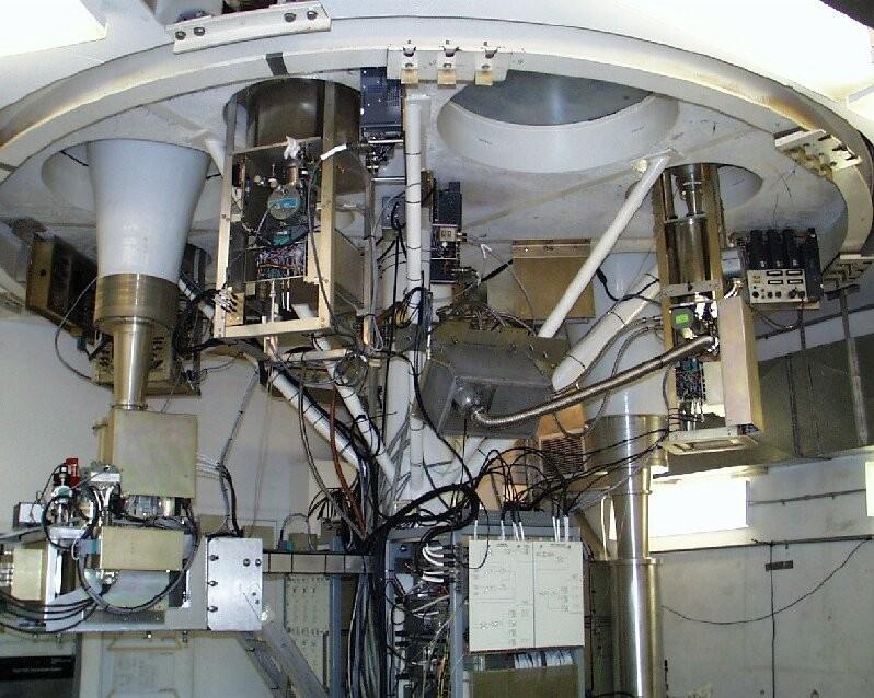
4 4.8 GHz (C-band) Interferometer Block Diagram Antenna Front End IF Key Amplifier Mixer X Correlato r Back End Correlator 44


5 55 Types of Antennas Wire antennas (λ 1m) Dipole Yagi Yagi Helix Helix Small arrays of the above (λ 1m) Reflector antennas ( λ 1m ) Hybrid antennas Wire reflectors Reflectors with dipole feeds
6 Basic Antenna Formulas Effective collecting area A(n,q,f) m2 P(θ, ϕ,ν ) A(θ, ϕ,ν ) I (θ, ϕ,ν )ΔνΔΩ On-axis response A0 = ha h = aperture efficiency Normalized pattern (primary beam) A(n,q,f) = A(n,q,f)/A0 Beam solid angle WA= A(n,q,f) dw all sky A0 WA = l2 l = wavelength, n = frequency 66
7 Aperture-Beam Fourier Transform Relationship What determines the beam shape? f(u,v) = complex aperture field distribution u,v = aperture coordinates (wavelengths) F(l,m) = complex far-field voltage pattern l = sinqcosf, m = sinqsinf F(l,m) = aperturef(u,v)exp(2pi(ul+vm))dudv f(u,v) = hemispheref(l,m)exp(-2pi(ul+vm))dldm For VLA: q3db = 1.02/D, First null = 1.22/D, D = reflector diameter in wavelengths 77

8 Antenna Mounts: Altitude over Azimuth Advantages Cost Gravity performance Disadvantages Zone of avoidance Beam rotates on sky 88
9 Beam Rotation on the Sky Parallactic angle 99

10 Antenna Mounts: Equatorial Advantages Tracking accuracy Beam doesn t rotate Disadvantages Cost Gravity performance Sources on horizon at pole 10
11 Reflector Optics Prime focus Offset Cassegrain Cassegrain focus Naysmith Dual Offset Beam Waveguide 11
12 Reflector Optics: Limitations Prime focus Over-illumination (spillover) can increase system temperature due to ground pick-up Number of receivers, and access to them, is limited Subreflector systems Can limit low frequency capability. Feed horn too large. Over-illumination by feed horn can exceed gain of refl ector s diffraction limited sidelobes Strong sources a few degrees away may limit image dynamic range Offset optics Support structure of offset feed is complex and expensive 12


 Beam")
 focus")

13 Reflector Optics: Examples Prime focus (GMRT) Offset Cassegrain (VLA) Beam Waveguide (NRO) Cassegrain focus (AT) Naysmith (OVRO) Dual Offset (GBT) 13


14 Feed Systems GBT VLA EVLA 14
15 Antenna Performance: Aperture Efficiency On axis response: A0 = ha Efficiency: h = hsf. hbl. hs. ht. hmisc hsf = Reflector surface efficiency Due to imperfections in reflector surface rms error s hsf = exp(-(4ps/l)2) e.g., s = l/16, hsf = 0.5 hbl = Blockage efficiency Caused by subreflector and its support structure hs = Feed spillover efficiency Fraction of power radiated by feed intercepted by subreflector ht = Feed illumination efficiency Outer parts of reflector illuminated at lower level than inner part hmisc= Reflector diffraction, feed position phase errors, feed match and loss 15 15

16 Surface of ALMA Vertex Antenna Surface measurements of DV02 made with holography Measured surface rms =10um 16
17 Antenna Performance: Aperture Efficiency Primary Beam pdl l=sin(q), D = antenna diameter in wavelengths contours:-3,-6,-10,-15,-20,-25, -30,-35,-40 db db = 10log(power ratio) = 20log(voltage ratio) VLA: q3db = 1.02/D, First null = 1.22/D Voltage radiation pattern, F(l,m) 17

18 Antenna Pointing: Practical Considerations Subreflector mount Reflector structure Quadrupod El encoder Alidade structure Rail flatness Foundation Azimuth encoder 18

19 Pointing: ALMA Vertex Antennas All-sky optical pointing on DV07 completed April 1-14 All-sky results (spec = 2 RMS) 0.77 ± 0.12 RMS at OSF 0.84 ± 0.13 RMS scaled to AOS All-sky and offset pointing within specifications! DV07 pointing residuals: Mangum, N. Emerson, Mundnich & Stenvers 19
20 Antenna Performance: Pointing Dq Pointing Accuracy Dq = rms pointing error Often Dq < q3db /10 acceptable, because A(q3dB /10) ~ 0.97 q3db Primary beam A(q) BUT, at half power point in beam A(q3dB /2 ± q3db /10)/A(q3dB /2) = ±0.3 For best VLA pointing use Reference Pointing. Dq = 3 arcsec = q3db 50 GHz 20
21 Antenna Performance: Polarization Antenna can modify apparent polarization properties of the source: Antenna structure Symmetry of the optics Reflections in the optics Curvature of the reflectors Quality of feed polarization splitter Constant across the beam Circularity of feed radiation patterns No instrumental polarization on-axis, But cross-polarization varies across the beam 21
22 Off-Axis Cross Polarization Cross-polarized aperture distribution Cross-polarized primary beam Field distribution in aperture of paraboloid fed by electric dipole VLA 4.8 GHz cross-polarized primary beam 22
23 Receivers: Noise Temperature Reference received power to the equivalent temperature of a matched load at the input to the receiver Rayleigh-Jeans approximation to Planck radiation law for a blackbody Pin = kbt (W) kb = Boltzman s constant (1.38*10-23 J/oK) When observing a radio source, Ttotal = TA + Tsys Tsys = system noise when not looking at a discrete radio source TA = source antenna temperature 23
24 Receivers: SEFD EVLA Sensitivities Band (GHz) TA = AS/(2kB) = KS S = source flux (Jy) SEFD = system equivalent flux density SEFD = Tsys/K (Jy) Tsys SEFD
25 EVLA Q-Band (40-50 GHz) Receiver Dewar Dorado 4IWC45-1 Remove NRAO CDL RCP GHz Post-AmpModule Caltech 3XM L/R RF=40-50 GHz GHz Magic-T MDL 22TH12B Pol Variable Attenuator NRAO Noise/COM NC 5222 ENR > 20 db Noise Diode TCal Old Some New Pamtech KYG2121-K2 (w/g) 18 dbm LO Splitter MAC Tech PA8207-2F GHz Limiting LO Amplifier Norden N GHz POut = 21.0 ± 0.5 dbm for ±6 dbm input x3 LNA LCP Isolator MICA T-708S GHz x3 35dB Atlantic Microwave AMC 1233 Septum Polarizer & Cal Coupler DC-Block Inmet 8055H GHz 24dB LNA TCal Tripler/Mixer Assembly Spacek 3XM L/R RF=40-50 GHz 35dB NRAO m B d 3 0 Integrated Isolator Dorado 4IWN45-1A (UG38 UG599) Isolator Mica T-610S GHz 24dB CDL Isolator Dorado 4IWN45-1A (UG38 UG599) Post-AmpModule Caltech 3XM L/R RF=40-50 GHz Tripler/Mixer Assembly Spacek 3XM L/R RF=40-50 GHz DC-Block Inmet 8055H GHz Isolator MICA T-708S GHz New 25
Antennas and Receivers in Radio Astronomy
 Antennas and Receivers in Radio Astronomy Mark McKinnon Eleventh Synthesis Imaging Workshop Socorro, June 10-17, 2008 Outline 2 Context Types of antennas Antenna fundamentals Reflector antennas Mounts
Antennas & Receivers in Radio Astronomy
 Antennas & Receivers in Radio Astronomy Mark McKinnon Fifteenth Synthesis Imaging Workshop 1-8 June 2016 Purpose & Outline Purpose: describe how antenna elements can affect the quality of images produced
Antennas. Greg Taylor. University of New Mexico Spring Astronomy 423 at UNM Radio Astronomy
 Antennas Greg Taylor University of New Mexico Spring 2011 Astronomy 423 at UNM Radio Astronomy Radio Window 2 spans a wide range of λ and ν from λ ~ 0.33 mm to ~ 20 m! (ν = 1300 GHz to 15 MHz ) Outline
Antennas. Greg Taylor. University of New Mexico Spring Astronomy 423 at UNM Radio Astronomy
 Antennas Greg Taylor University of New Mexico Spring 2017 Astronomy 423 at UNM Radio Astronomy Outline 2 Fourier Transforms Interferometer block diagram Antenna fundamentals Types of antennas Antenna performance
EVLA Scientific Commissioning and Antenna Performance Test Check List
 EVLA Scientific Commissioning and Antenna Performance Test Check List C. J. Chandler, C. L. Carilli, R. Perley, October 17, 2005 The following requirements come from Chapter 2 of the EVLA Project Book.
Signal Flow & Radiometer Equation. Aletha de Witt AVN-Newton Fund/DARA 2018 Observational & Technical Training HartRAO
 Signal Flow & Radiometer Equation Aletha de Witt AVN-Newton Fund/DARA 2018 Observational & Technical Training HartRAO Understanding Radio Waves The meaning of radio waves How radio waves are created -
School of Electrical Engineering. EI2400 Applied Antenna Theory Lecture 8: Reflector antennas
 School of Electrical Engineering EI2400 Applied Antenna Theory Lecture 8: Reflector antennas Reflector antennas Reflectors are widely used in communications, radar and radio astronomy. The largest reflector
Richard Dodson 1/28/2014 NARIT-KASI Winter School
 Goals: Technical introduction very short So what to cover? Things which are essential: How radio power is received - I How an interferometer works -II Antenna Fundamentals Black Body Radiation Brightness
Aperture Antennas. Reflectors, horns. High Gain Nearly real input impedance. Huygens Principle
 Antennas 97 Aperture Antennas Reflectors, horns. High Gain Nearly real input impedance Huygens Principle Each point of a wave front is a secondary source of spherical waves. 97 Antennas 98 Equivalence
EVLA Front-End CDR. EVLA Ka-Band (26-40 GHz) Receiver
 Receiver") EVLA Front-End CDR EVLA Ka-Band (26-40 GHz) Receiver 1 EVLA Ka-Band Receiver Overview 1) General Description 2) Block Diagram 3) Noise & Headroom Model 4) Feed & Thermal Gap 5) RF Tree - Phase-Shifter
EVLA Front-End CDR EVLA Ka-Band (26-40 GHz) Receiver 1 EVLA Ka-Band Receiver Overview 1) General Description 2) Block Diagram 3) Noise & Headroom Model 4) Feed & Thermal Gap 5) RF Tree - Phase-Shifter
Submillimeter (continued)
") Submillimeter (continued) Dual Polarization, Sideband Separating Receiver Dual Mixer Unit The 12-m Receiver Here is where the receiver lives, at the telescope focus Receiver Performance T N (noise temperature)
Submillimeter (continued) Dual Polarization, Sideband Separating Receiver Dual Mixer Unit The 12-m Receiver Here is where the receiver lives, at the telescope focus Receiver Performance T N (noise temperature)
Receiver Performance and Comparison of Incoherent (bolometer) and Coherent (receiver) detection
 and Coherent (receiver) detection") At ev gap /h the photons have sufficient energy to break the Cooper pairs and the SIS performance degrades. Receiver Performance and Comparison of Incoherent (bolometer) and Coherent (receiver) detection
At ev gap /h the photons have sufficient energy to break the Cooper pairs and the SIS performance degrades. Receiver Performance and Comparison of Incoherent (bolometer) and Coherent (receiver) detection
Fundamentals of the GBT and Single-Dish Radio Telescopes Dr. Ron Maddalena
 Fundamentals of the GB and Single-Dish Radio elescopes Dr. Ron Maddalena March 2016 Associated Universities, Inc., 2016 National Radio Astronomy Observatory Green Bank, WV National Radio Astronomy Observatory
Reflector antennas and their feeds
 Reflector antennas and their feeds P. Hazdra, M. Mazanek,. hazdrap@fel.cvut.cz Department of Electromagnetic Field Czech Technical University in Prague, FEE www.elmag.org v. 23.4.2015 Outline Simple reflector
ATCA Antenna Beam Patterns and Aperture Illumination
 1 AT 39.3/116 ATCA Antenna Beam Patterns and Aperture Illumination Jared Cole and Ravi Subrahmanyan July 2002 Detailed here is a method and results from measurements of the beam characteristics of the
Introduction to DSTV Dish Observations. Alet de Witt AVN Technical Training 2016
 Introduction to DSTV Dish Observations Alet de Witt AVN Technical Training 2016 Outline Theory: - Radio Waves - Radio Telescope Antennas - Angular Sizes - Brightness Temperature and Antenna Temperature
OPTICS OF SINGLE BEAM, DUAL BEAM & ARRAY RECEIVERS ON LARGE TELESCOPES J A M E S W L A M B, C A L T E C H
 OPTICS OF SINGLE BEAM, DUAL BEAM & ARRAY RECEIVERS ON LARGE TELESCOPES J A M E S W L A M B, C A L T E C H OUTLINE Antenna optics Aberrations Diffraction Single feeds Types of feed Bandwidth Imaging feeds
Progress Towards Coherent Multibeam Arrays
 Progress Towards Coherent Multibeam Arrays Doug Henke NRC Herzberg Astronomy and Astrophysics, Victoria, Canada August 2016 ALMA Band 3 Receiver (84 116 GHz) Dual linear, 2SB Feed horn OMT (two linear
Introduction to Radio Astronomy!
 Introduction to Radio Astronomy! Sources of radio emission! Radio telescopes - collecting the radiation! Processing the radio signal! Radio telescope characteristics! Observing radio sources Sources of
G. Serra.
 G. Serra gserra@oa-cagliari.inaf.it on behalf of Metrology team* *T. Pisanu, S. Poppi, F.Buffa, P. Marongiu, R. Concu, G. Vargiu, P. Bolli, A. Saba, M.Pili, E.Urru Astronomical Observatory of Cagliari
Evaluation of Suitable Feed Systemes
 Evaluation of Suitable Feed Systemes Review of the Ring Focus Antenna Quadridge Horn Eleven Feed Coaxial Horn and Multiband Corrugated Horn Conclusion MIRAD Microwave AG Broadband Feedsystems IVS VLBI21
EVLA Antenna and Array Performance. Rick Perley
 EVLA Antenna and Array Performance System Requirements EVLA Project Book, Chapter 2, contains the EVLA system requirements. For most, astronomical tests are necessary to determine if the array meets requirements.
The TWIN-Radiotelescopes Wettzell;
 The TWIN-Radiotelescopes Wettzell Critical Design Points G. Kronschnabl, BKG; Dr. A. Neidhardt, TUM; Dr. K. Pausch, Vertex GmbH; W. Göldi, Mirad; R. Rayet, Callisto; A. Emrich, Omnisys; 1 VLBI 2010 VLBI
LE/ESSE Payload Design
 LE/ESSE4360 - Payload Design 4.3 Communications Satellite Payload - Hardware Elements Earth, Moon, Mars, and Beyond Dr. Jinjun Shan, Professor of Space Engineering Department of Earth and Space Science
What does reciprocity mean
 Antennas Definition of antenna: A device for converting electromagnetic radiation in space into electrical currents in conductors or vice-versa. Radio telescopes are antennas Reciprocity says we can treat
5 RECEIVERS TABLE TBD: EVLA RECEIVER FREQUENCY RANGES AND OPERATING TEMPERATURES
 EVLA Project Book, Chapter 5. 5 RECEIVERS Robert Hayward, Ed Szpindor, and Daniel J. Mertely Last changed 2001-Oct-30 Revision History 2001-July-01: Initial release. 2001-Oct-01: Sys-def & detail added.
A Crash Course in Radio Astronomy and Interferometry: 1. Basic Radio/mm Astronomy
 A Crash Course in Radio Astronomy and Interferometry: 1. Basic Radio/mm Astronomy James Di Francesco National Research Council of Canada North American ALMA Regional Center Victoria (thanks to S. Dougherty,
NATIONAL RADIO ASTRONOMY OBSERVATORY CHARLOTTESVILLE, VIRGINIA. ELECTRONICS DIVISION INTERNAL REPORT No. 275 CRYOGENIC, HEMT, LOW-NOISE RECEIVERS
 NATIONAL RADIO ASTRONOMY OBSERVATORY CHARLOTTESVILLE, VIRGINIA ELECTRONICS DIVISION INTERNAL REPORT No. 275 CRYOGENIC, HEMT, LOW-NOISE RECEIVERS FOR 1.3 TO 43 GHz RANGE S. WEINREB M. W. POSPIESZALSKI R.
Aperture antennas. Ahmed FACHAR, Universidad Politécnica de Madrid (Technical University of Madrid, UPM)
") Aperture antennas Ahmed FACHAR, ahmedfach@gr.ssr.upm.es Universidad Politécnica de Madrid (Technical University of Madrid, UPM) Outline Introduction Horn antennas Introduction Rectangular horns Conical
Aperture antennas Ahmed FACHAR, ahmedfach@gr.ssr.upm.es Universidad Politécnica de Madrid (Technical University of Madrid, UPM) Outline Introduction Horn antennas Introduction Rectangular horns Conical
EVLA Memo 137 Performance Tests of the EVLA K, Ka, and Q-Band Receivers
 EVLA Memo 137 Performance Tests of the EVLA K, Ka, and Q-Band Receivers Rick Perley, Bob Hayward and Bryan Butler NRAO August 4, 2009 Abstract Efficiency observations performed in January and February
Newsletter 4.4. Antenna Magus version 4.4 released! Array synthesis reflective ground plane addition. July 2013
 Newsletter 4.4 July 2013 Antenna Magus version 4.4 released! We are pleased to announce the new release of Antenna Magus Version 4.4. This release sees the addition of 5 new antennas: Horn-fed truncated
Introduction to Radio Astronomy. Richard Porcas Max-Planck-Institut fuer Radioastronomie, Bonn
 Introduction to Radio Astronomy Richard Porcas Max-Planck-Institut fuer Radioastronomie, Bonn 1 Contents Radio Waves Radio Emission Processes Radio Noise Radio source names and catalogues Radio telescopes
Phased Array Feeds A new technology for multi-beam radio astronomy
 Phased Array Feeds A new technology for multi-beam radio astronomy Aidan Hotan ASKAP Deputy Project Scientist 2 nd October 2015 CSIRO ASTRONOMY AND SPACE SCIENCE Outline Review of radio astronomy concepts.
Aperture antennas. Andrés García, Francico José Cano, Alfonso Muñoz. (Technical University of Madrid, UPM)
") Aperture antennas Andrés García, Francico José Cano, Alfonso Muñoz andresg@gr.ssr.upm.es, ssr francisco@gr.ssr.upm.es, ssr alfonso@gr.ssr.upm.esssr Universidad Politécnica de Madrid (Technical University
Aperture antennas Andrés García, Francico José Cano, Alfonso Muñoz andresg@gr.ssr.upm.es, ssr francisco@gr.ssr.upm.es, ssr alfonso@gr.ssr.upm.esssr Universidad Politécnica de Madrid (Technical University
EC ANTENNA AND WAVE PROPAGATION
 EC6602 - ANTENNA AND WAVE PROPAGATION FUNDAMENTALS PART-B QUESTION BANK UNIT 1 1. Define the following parameters w.r.t antenna: i. Radiation resistance. ii. Beam area. iii. Radiation intensity. iv. Directivity.
The magnetic surface current density is defined in terms of the electric field at an aperture as follows: 2E n (6.1)
") Chapter 6. Aperture antennas Antennas where radiation occurs from an open aperture are called aperture antennas. xamples include slot antennas, open-ended waveguides, rectangular and circular horn antennas,
Chapter 6. Aperture antennas Antennas where radiation occurs from an open aperture are called aperture antennas. xamples include slot antennas, open-ended waveguides, rectangular and circular horn antennas,
NMA Antenna and Receiver Concepts
 EVLA Planning Workshop NRAO, Socorro, NM August 23, 2001 NMA Antenna and Receiver Concepts 1. Station Cost Equation 2. Hydroformed Antennas 3. Wideband Receivers Sander Weinreb, Caltech/JPL sweinreb@caltech.edu
Phased Array Feeds A new technology for wide-field radio astronomy
 Phased Array Feeds A new technology for wide-field radio astronomy Aidan Hotan ASKAP Project Scientist 29 th September 2017 CSIRO ASTRONOMY AND SPACE SCIENCE Outline Review of radio astronomy concepts
RADIATION PATTERNS. The half-power (-3 db) beamwidth is a measure of the directivity of the antenna.
 beamwidth is a measure of the directivity of the antenna.") RADIATION PATTERNS The radiation pattern is a graphical depiction of the relative field strength transmitted from or received by the antenna. Antenna radiation patterns are taken at one frequency, one
RADIATION PATTERNS The radiation pattern is a graphical depiction of the relative field strength transmitted from or received by the antenna. Antenna radiation patterns are taken at one frequency, one
REPORT ITU-R SA.2098
 Rep. ITU-R SA.2098 1 REPORT ITU-R SA.2098 Mathematical gain models of large-aperture space research service earth station antennas for compatibility analysis involving a large number of distributed interference
Chapter 41 Deep Space Station 13: Venus
 Chapter 41 Deep Space Station 13: Venus The Venus site began operation in Goldstone, California, in 1962 as the Deep Space Network (DSN) research and development (R&D) station and is named for its first
ANTENNA INTRODUCTION / BASICS
 ANTENNA INTRODUCTION / BASICS RULES OF THUMB: 1. The Gain of an antenna with losses is given by: 2. Gain of rectangular X-Band Aperture G = 1.4 LW L = length of aperture in cm Where: W = width of aperture
INSTITUTE OF AERONAUTICAL ENGINEERING Dundigal, Hyderabad ELECTRONICS AND COMMUNIACTION ENGINEERING QUESTION BANK
 INSTITUTE OF AERONAUTICAL ENGINEERING Dundigal, Hyderabad - 500 04 ELECTRONICS AND COMMUNIACTION ENGINEERING QUESTION BANK Course Name : Antennas and Wave Propagation (AWP) Course Code : A50418 Class :
EVLA Front-End CDR. Overview & System Requirements
 EVLA Front-End CDR Overview & System Requirements 1 Overview & System Requirements Introduction to the EVLA Front-End Task EVLA vs. VLA Feeds Receivers System Requirements, including: System Temperatures
GBT Spectral Baseline Investigation Rick Fisher, Roger Norrod, Dana Balser (G. Watts, M. Stennes)
") GBT Spectral Baseline Investigation Rick Fisher, Roger Norrod, Dana Balser (G. Watts, M. Stennes) Points to Note: Wider bandwidths than were used on 140 Foot Cleaner antenna so other effects show up Larger
GBT Spectral Baseline Investigation Rick Fisher, Roger Norrod, Dana Balser (G. Watts, M. Stennes) Points to Note: Wider bandwidths than were used on 140 Foot Cleaner antenna so other effects show up Larger
Receivers for. FFRF Tutorial by Tom Clark, NASA/GSFC & NVI Wettzell, March 19, 2009
 Receivers for VLBI2010 FFRF Tutorial by Tom Clark, NASA/GSFC & NVI Wettzell, March 19, 2009 There is no fundamental difference between the receivers for PRIME FOCUS & CASSEGRAIN Except for: the beamwidth
BHARATHIDASAN ENGINEERING COLLEGE NATTARAMPALLI Frequently Asked Questions (FAQ) Unit 1
 Unit 1") BHARATHIDASAN ENGINEERING COLLEGE NATTARAMPALLI 635854 Frequently Asked Questions (FAQ) Unit 1 Degree / Branch : B.E / ECE Sem / Year : 3 rd / 6 th Sub Name : Antennas & Wave Propagation Sub Code : EC6602
BHARATHIDASAN ENGINEERING COLLEGE NATTARAMPALLI 635854 Frequently Asked Questions (FAQ) Unit 1 Degree / Branch : B.E / ECE Sem / Year : 3 rd / 6 th Sub Name : Antennas & Wave Propagation Sub Code : EC6602
Antennas & wave Propagation ASSIGNMENT-I
 Shri Vishnu Engineering College for Women :: Bhimavaram Department of Electronics & Communication Engineering Antennas & wave Propagation 1. Define the terms: i. Antenna Aperture ii. Beam Width iii. Aperture
Day 1 Session 2. Earth Station Technology
 Day 1 Session 2 Earth Station Technology 1 1- Types of antennas Satellites being far from earth require directional antennas in order to communicate. A directional antenna normally uses a parabolic reflector
Holography Transmitter Design Bill Shillue 2000-Oct-03
 Holography Transmitter Design Bill Shillue 2000-Oct-03 Planned Photonic Reference Distribution for Test Interferometer The transmitter for the holography receiver is made up mostly of parts that are already
ALMA Sensitivity Metric for Science Sustainability Projects
 ALMA Memo 602 ALMA Sensitivity Metric for Science Sustainability ALMA-35.00.101.666-A-SPE 2017 01 23 Description Document Jeff Mangum (NRAO) Page 2 Change Record Revision Date Author Section/ Remarks Page
EVLA Project Book, Chapter 4 4 Antennas and Feeds. Jim Ruff, Ed Szpindor, S. Srikanth Last changed 2002-Feb-28
 EVLA Project Book, Chapter 4 4 Antennas and Feeds Jim Ruff, Ed Szpindor, S. Srikanth Last changed 2002-Feb-28 Revision History: 2002-Feb-28, Rev C Add paragraph on RFI; identify cable, tubing, and ducting
EVLA Memo #119 Wide-Band Sensitivity and Frequency Coverage of the EVLA and VLA L-Band Receivers
 EVLA Memo #119 Wide-Band Sensitivity and Frequency Coverage of the EVLA and VLA L-Band Receivers Rick Perley and Bob Hayward January 17, 8 Abstract We determine the sensitivities of the EVLA and VLA antennas
arxiv:astro-ph/ v1 21 Jun 2006
 Ð Ú Ø ÓÒ Ò Ð Ô Ò Ò Ó Ø ËÅ ÒØ ÒÒ ÓÙ ÔÓ Ø ÓÒ Satoki Matsushita a,c, Masao Saito b,c, Kazushi Sakamoto b,c, Todd R. Hunter c, Nimesh A. Patel c, Tirupati K. Sridharan c, and Robert W. Wilson c a Academia
Antenna Fundamentals. Microwave Engineering EE 172. Dr. Ray Kwok
 Antenna Fundamentals Microwave Engineering EE 172 Dr. Ray Kwok Reference Antenna Theory and Design Warran Stutzman, Gary Thiele, Wiley & Sons (1981) Microstrip Antennas Bahl & Bhartia, Artech House (1980)
C-band Circular Corrugated horn for the SRT. Beam Waveguide Focus. L. Cresci, P. Curioni, V. Natale, R. Nesti, A.Orfei, D. Panella, J.
 C-band Circular Corrugated horn for the SRT Beam Waveguide Focus GAI4 Memo Series I.N.A.F GAI4-TM-13.1 7/5/211 Abstract In this report the authors present the design of a circular corrugated horn for
ADVANCED 14/12 AND 30/20 GHz MULTIPLE BEAM ANTENNA TECHNOLOGY FOR COMMUNICATIONS SATELLITES
 ADVANCED 14/12 AND 30/20 GHz MULTIPLE BEAM ANTENNA TECHNOLOGY FOR COMMUNICATIONS SATELLITES C.C. Chen TRW Defense and Space Systems Group Redondo Beach, CA 90278 ABSTRACT This paper discusses recent TRW
EVLA System Commissioning Results
 EVLA System Commissioning Results EVLA Advisory Committee Meeting, March 19-20, 2009 Rick Perley EVLA Project Scientist t 1 Project Requirements EVLA Project Book, Chapter 2, contains the EVLA Project
CHAPTER 3 SIDELOBE PERFORMANCE OF REFLECTOR / ANTENNAS
 16 CHAPTER 3 SIDELOBE PERFORMANCE OF REFLECTOR / ANTENNAS 3.1 INTRODUCTION In the past many authors have investigated the effects of amplitude and phase distributions over the apertures of both array antennas
Handbook of Reflector Antennas
 Handbook of Reflector Antennas and Feed Systems Volume I Theory and Design of Reflectors Satish K. Sharma Sudhakar Rao Lotfollah Shafai Preface Acknowledgments ix x Introduction 1 1.1 Introduction 1 1.2
Sub-millimeter Wave Planar Near-field Antenna Testing
 Sub-millimeter Wave Planar Near-field Antenna Testing Daniёl Janse van Rensburg 1, Greg Hindman 2 # Nearfield Systems Inc, 1973 Magellan Drive, Torrance, CA, 952-114, USA 1 drensburg@nearfield.com 2 ghindman@nearfield.com
Recent progress and future development of Nobeyama 45-m Telescope
 Recent progress and future development of Nobeyama 45-m Telescope Masao Saito: Director of Nobeyama Radio Observatory Tetsuhiro Minamidani: Nobeyama Radio Observatory Outline Nobeyama 45-m Telescope Recent
ANTENNA INTRODUCTION / BASICS
 Rules of Thumb: 1. The Gain of an antenna with losses is given by: G 0A 8 Where 0 ' Efficiency A ' Physical aperture area 8 ' wavelength ANTENNA INTRODUCTION / BASICS another is:. Gain of rectangular X-Band
Phased Array Feeds & Primary Beams
 Phased Array Feeds & Primary Beams Aidan Hotan ASKAP Deputy Project Scientist 3 rd October 2014 CSIRO ASTRONOMY AND SPACE SCIENCE Outline Review of parabolic (dish) antennas. Focal plane response to a
VLBI2010 Current status of the TWIN radio telescope project at Wettzell, Germany
 VLBI2010 Current status of the TWIN radio telescope project at Wettzell, Germany Alexander Neidhardt, FESG/TU München (on behalf of the BKG) G. Kronschnabl, (BKG); Hase, H. (BKG); Schreiber, U. (BKG);
PRIME FOCUS FEEDS FOR THE COMPACT RANGE
 PRIME FOCUS FEEDS FOR THE COMPACT RANGE John R. Jones Prime focus fed paraboloidal reflector compact ranges are used to provide plane wave illumination indoors at small range lengths for antenna and radar
EVLA Receivers PDR. (4m, P,) L, S, C BAND RECEIVERS. AuthorDaniel (Mert) Mertely
 L, S, C BAND RECEIVERS. AuthorDaniel (Mert) Mertely") EVLA Receivers PDR (4m, P,) L, S, C BAND RECEIVERS Daniel (Mert) Mertely 1 Trx Projections EVLA RX FREQ RANGES AND OP TEMPS: REQUIRED vs. PROJECTED BND FRQ REQ CURNT CURNT CALC IDR RANGE Tsys (2) Tsys
EVLA Receivers PDR (4m, P,) L, S, C BAND RECEIVERS Daniel (Mert) Mertely 1 Trx Projections EVLA RX FREQ RANGES AND OP TEMPS: REQUIRED vs. PROJECTED BND FRQ REQ CURNT CURNT CALC IDR RANGE Tsys (2) Tsys
Focal Plane Receiver Architecture for ASTE and Total Power Array of ALMA. Jung-Won Lee
 Focal Plane Receiver Architecture for ASTE and Total Power Array of ALMA Jung-Won Lee Korea Astronomy and Space Science Institute ASTE-ALMA Development Workshop, June 17, 2014 Focal Plane Array: Sampling
W1GHZ W1GHZ W1GHZ W1GHZ W1GHZ W1GHZ W1GHZ W1GHZ
 Section 6.0 Introduction Chapter 6 Feeds for Parabolic Dish Antennas Paul Wade 1994,1997,1998,1999 The key to good parabolic dish antenna performance is the feed antenna, the source of radiated energy
A NEW WIDEBAND DUAL LINEAR FEED FOR PRIME FOCUS COMPACT RANGES
 A NEW WIDEBAND DUAL LINEAR FEED FOR PRIME FOCUS COMPACT RANGES by Ray Lewis and James H. Cook, Jr. ABSTRACT Performance trade-offs are Investigated between the use of clustered waveguide bandwidth feeds
Sources classification
 Sources classification Radiometry relates to the measurement of the energy radiated by one or more sources in any region of the electromagnetic spectrum. As an antenna, a source, whose largest dimension
Dr. John S. Seybold. November 9, IEEE Melbourne COM/SP AP/MTT Chapters
 Antennas Dr. John S. Seybold November 9, 004 IEEE Melbourne COM/SP AP/MTT Chapters Introduction The antenna is the air interface of a communication system An antenna is an electrical conductor or system
W1GHZ W1GHZ W1GHZ W1GHZ W1GHZ W1GHZ W1GHZ W1GHZ
 Online Online Online Online Online Online (ex-n1bwt) (ex-n1bwt) (ex-n1bwt) (ex-n1bwt) (ex-n1bwt) (ex-n1bwt) (ex-n1bwt) Online (ex-n1bwt) W1GHZ W1GHZ Microwave Antenna Book Antenna BookOnline W1GHZ W1GHZ
New Trends on Receivers Development" May 30, 2005, Medicina. RECEIVING SYSTEMs for the ANTENNAS OPERATED by the INSTITUTE of RADIOASTRONOMY in ITALY
 New Trends on Receivers Development" May 30, 2005, Medicina RECEIVING SYSTEMs for the ANTENNAS OPERATED by the INSTITUTE of RADIOASTRONOMY in ITALY Alessandro Orfei IRA-INAF, Medicina station (Italy) RADIONET
Antenna Measurement Uncertainty Method for Measurements in Compact Antenna Test Ranges
 Antenna Measurement Uncertainty Method for Measurements in Compact Antenna Test Ranges Stephen Blalock & Jeffrey A. Fordham MI Technologies Suwanee, Georgia, USA Abstract Methods for determining the uncertainty
AN RF MONOPULSE ATTITUDE SENSING SYSTEM
 AN RF MONOPULSE ATTTUDE SENSNG SYSTEM J. B. TAMMES Hollandse Signaalapparaten Hengelo, The Netherlands J. J. BLEWES COMSAT Corporation Clarksburg, Maryland Summary. The application of RF monopulse sensing
MMA Memo 143: Report of the Receiver Committee for the MMA
 MMA Memo 143: Report of the Receiver Committee for the MMA 25 September, 1995 John Carlstrom Darrel Emerson Phil Jewell Tony Kerr Steve Padin John Payne Dick Plambeck Marian Pospieszalski Jack Welch, chair
Phased Array Feeds for the SKA. WP2.2.3 PAFSKA Consortium CSIRO ASTRON DRAO NRAO BYU OdP Nancay Cornell U Manchester
 Phased Array Feeds for the SKA WP2.2.3 PAFSKA Consortium CSIRO ASTRON DRAO NRAO BYU OdP Nancay Cornell U Manchester Dish Array Hierarchy Dish Array L5 Elements PAF Dish Single Pixel Feeds L4 Sub systems
KULLIYYAH OF ENGINEERING
 KULLIYYAH OF ENGINEERING DEPARTMENT OF ELECTRICAL & COMPUTER ENGINEERING ANTENNA AND WAVE PROPAGATION LABORATORY (ECE 4103) EXPERIMENT NO 3 RADIATION PATTERN AND GAIN CHARACTERISTICS OF THE DISH (PARABOLIC)
Antenna Fundamentals Basics antenna theory and concepts
 Antenna Fundamentals Basics antenna theory and concepts M. Haridim Brno University of Technology, Brno February 2017 1 Topics What is antenna Antenna types Antenna parameters: radiation pattern, directivity,
A new K-band (18-26 GHz) 7-horn multi-feed receiver: Calibration campaign at Medicina 32 m dish
 7-horn multi-feed receiver: Calibration campaign at Medicina 32 m dish") A new K-band (18-26 GHz) 7-horn multi-feed receiver: Calibration campaign at Medicina 32 m dish R.Verma, G.Maccaferri, A.Orfei I.Prandoni, L.Gregorini IRA 430/09 Contents 1 6 1.1 Goals............................................
A new K-band (18-26 GHz) 7-horn multi-feed receiver: Calibration campaign at Medicina 32 m dish R.Verma, G.Maccaferri, A.Orfei I.Prandoni, L.Gregorini IRA 430/09 Contents 1 6 1.1 Goals............................................
High Fidelity Imaging of Extended Sources. Rick Perley NRAO Socorro, NM
 High Fidelity Imaging of Extended Sources Rick Perley NRAO Socorro, NM A Brief History of Calibration (VLA) An Amazing Fact: The VLA was proposed, and funded, without any real concept of how to calibrate
EVLA Technical Performance
 EVLA Technical Performance With much essential help from Barry Clark, Ken Sowinski, Vivek Dhawan, Walter Brisken, George Moellenbrock, Bob Hayward, Dan Mertely, and many others. 1 Performance Requirements
Reflector Antenna, its Mount and Microwave. Absorbers for IIP Radiometer Experiments
 Reflector Antenna, its Mount and Microwave Absorbers for IIP Radiometer Experiments Nakasit Niltawach, and Joel T. Johnson May 8 th, 2003 1 Introduction As mentioned in [1], measurements are required for
Final Feed Selection Study For the Multi Beam Array System
 National Astronomy and Ionosphere Center Arecibo Observatory Focal Array Memo Series Final Feed Selection Study For the Multi Beam Array System By: Germán Cortés-Medellín CORNELL July/19/2002 U n i v e
essential requirements is to achieve very high cross-polarization discrimination over a
 INTRODUCTION CHAPTER-1 1.1 BACKGROUND The antennas used for specific applications in satellite communications, remote sensing, radar and radio astronomy have several special requirements. One of the essential
Atonnm. Lincoln Laboratory MASSACH1 SETTS INSTITUTE OF TECHNOLOGY. Technical Report TR A.J. Fenn S. Srikanth. 29 November 2004 ESC-TR
 ESC-TR-2004-090 Technical Report TR-1099 Radiation Pattern Measurements of the Expanded Very Large Array (EVLA) C-Band Feed Horn in the MIT Lincoln Laboratory New Compact Range: Range Validation at 4 GHz
COMPARATIVE ANALYSIS BETWEEN CONICAL AND GAUSSIAN PROFILED HORN ANTENNAS
 Progress In Electromagnetics Research, PIER 38, 147 166, 22 COMPARATIVE ANALYSIS BETWEEN CONICAL AND GAUSSIAN PROFILED HORN ANTENNAS A. A. Kishk and C.-S. Lim Department of Electrical Engineering The University
ALMA Interferometer and Band 7 Cartridge
 ALMA Interferometer and Band 7 Cartridge B7 Cartridge designed, assembled and tested by: S. Mahieu, D. Maier (mixer team lead), B. Lazareff (now at IPAG) G. Celestin, J. Chalain, D. Geoffroy, F. Laslaz,
L-Band and X-Band Antenna Design and Development for NeXtRAD
 L-Band and X-Band Antenna Design and Development for NeXtRAD S. T. Paine, P. Cheng, D. W. O Hagan, M. R. Inggs, H. D. Griffiths* Department of Electrical Engineering Radar Remote Sensing Group University
ngvla Technical Overview
 ngvla Technical Overview Mark McKinnon, Socorro, NM Outline ngvla Nominal Technical Parameters Technical Issues to Consider in Science Use Cases Programmatics Additional Information Pointed or Survey Telescope?
Analysis and Compensation of Subreflector Displacement for the Parabolic Antenna of a Radio Telescope
 Progress In Electromagnetics Research M, Vol. 44, 59 68, 215 Analysis and Compensation of Subreflector Displacement for the Parabolic Antenna of a Radio Telescope Lan Chen 1, Zheng Xiong Sun 1, Jin Qing
EVLA Memo 103 Performance Tests of the EVLA K- and Q-Band Systems
 EVLA Memo 103 Performance Tests of the EVLA K- and Q-Band Systems Rick Perley, Bob Hayward, Bryan Butler, Vivek Dhawan NRAO March 1, 2006 Abstract Sensitivity measurements performed on EVLA antenna #14
Chapter 4 The RF Link
 Chapter 4 The RF Link The fundamental elements of the communications satellite Radio Frequency (RF) or free space link are introduced. Basic transmission parameters, such as Antenna gain, Beamwidth, Free-space
Noise generators. Spatial Combining of Multiple Microwave Noise Radiators NOISE ARRAY. This article reports on. experiments to increase the
 From April 2008 High Frequency Electronics Copyright 2008 Summit Technical Media LLC Spatial Combining of Multiple Microwave Noise Radiators By Jiri Polivka Spacek Labs Inc. Noise generators This article
Multiplying Interferometers
 Multiplying Interferometers L1 * L2 T + iv R1 * R2 T - iv L1 * R2 Q + iu R1 * L2 Q - iu Since each antenna can output both L and R polarization, all 4 Stokes parameters are simultaneously measured without
Final Examination. 22 April 2013, 9:30 12:00. Examiner: Prof. Sean V. Hum. All non-programmable electronic calculators are allowed.
 UNIVERSITY OF TORONTO FACULTY OF APPLIED SCIENCE AND ENGINEERING The Edward S. Rogers Sr. Department of Electrical and Computer Engineering ECE 422H1S RADIO AND MICROWAVE WIRELESS SYSTEMS Final Examination
RA3AQ Septum Feed Simulations
 RA3AQ Septum Feed Simulations Paul Wade W1GHZ 2008 w1ghz@arrl.net Dmitri, RA3AQ developed a feed in 2007 with a square septum and a round aperture, and updated it in late 2008. I received this drawing
EEM.Ant. Antennas and Propagation
 EEM.ant/0304/08pg/Req: None 1/8 UNIVERSITY OF SURREY Department of Electronic Engineering MSc EXAMINATION EEM.Ant Antennas and Propagation Duration: 2 Hours Spring 2003/04 READ THESE INSTRUCTIONS Answer
Figure 1 Photo of an Upgraded Low Band Receiver
 NATIONAL RADIO ASTRONOMY OBSERVATORY SOCORRO, NEW MEXICO EVLA TECHNICAL REPORT #175 LOW BAND RECEIVER PERFORMANCE SEPTMBER 27, 2013 S.DURAND, P.HARDEN Upgraded low band receivers, figure 1, were installed