Introduction to Radio Astronomy. Richard Porcas Max-Planck-Institut fuer Radioastronomie, Bonn
|
|
|
- Brenda Fields
- 6 years ago
- Views:
Transcription
1 Introduction to Radio Astronomy Richard Porcas Max-Planck-Institut fuer Radioastronomie, Bonn
2 1 Contents Radio Waves Radio Emission Processes Radio Noise Radio source names and catalogues Radio telescopes Radio receivers - the feed Description of noise Receivers: amplification Receivers: mixing and detection Signals for Interferometry Radio disturbances
3 2 Radio Waves EM-waves in frequency range 30 MHz to 800 GHz wavelengths 10 m 0.4 mm; a factor 30,000 The new interferometer arrays LOFAR and ALMA will explore these two extremes
4 Radio frequency band designations L band 1 to 2 GHz S band 2 to 4 GHz C band 4 to 8 GHz X band 8 to 12 GHz Ku band 12 to 18 GHz K band 18 to 26 GHz Ka band 26 to 40 GHz Q band 30 to 50 GHz U band 40 to 60 GHz V band 50 to 75 GHz E band 60 to 90 GHz W band 75 to 110 GHz F band 90 to 140 GHz D band 110 to 170 GHz The term P band is sometimes used for UHF frequencies below L-band.
5 3 Radio Emission Processes Thermal emission; black-body spectrum Example: the Moon Free-free emission (Bremsstrahlung) from ionized gas Example: HII regions Synchrotron emission from charged relativistic particles in magnetic field Example: AGN jets Spectral line emission from atoms, radicals, molecules Example: Neutral hydrogen (HI); 1421 MHz (21 cm) Also: spectral line absorption against background continuum emission Pulsar emission (probably curvature radiation)

6 Figure 1: Karl Jansky
7 4 Radio Noise Cosmic objects producing radio waves are called radio sources Radio emission often referred to as radio noise First detection of radio source by Karl Jansky in Measure of radio source strength is its flux density, S (sometimes incorrectly termed flux ) Unit of flux density = jansky (Jy) = WHz 1 m 2 Flux density calibration sources at different frequencies Spectral index, α for continuum sources: S α ν +α steep spectrum: α < 0.5 (opt. thin synchrotron) inverted spectrum: α > 0.0 flat spectrum: 0.0 > α > 0.5
8 Surface brightness of an extended source is the flux density per unit surface area. Units often used in maps or images of a radio source are mjy/beam (where beam is the area of the point source response in the map). Physical unit is brightness temperature, T b : the temperature at which a black body would give the same radio emission per unit area T b = Sλ 2 /2kΩ where S is the source flux density, λ is the observing wavelength, k is Boltzmann s constant and Ω is the observed solid angle of the emission.
9 5 Radio source names and catalogues Radio sky dominated by very different population from optical sky Radio sky looks different at different frequencies because of the wide range of frequencies (over 4 decades) and the range of different spectral indices. At low frequencies the sky is domininated by steep spectrum sources, mostly synchroton emitters. At high frequencies there are more flat and inverted spectrum sources. Source names often from catalogues derived from flux densitylimited surveys of the radio sky at particular frequencies, especially if they are more prominent in the radio sky
10 Some well-known examples: CYGNUS A - the strongest source in Cygnus VIRGO A - but also M87 3C strong quasar from the 3rd Cambridge Catalogue (178 MHz) 3C 84 - but also N-galaxy NGC 1275 PKS B from the Parkes Catalogue (hhmm+dd.d)
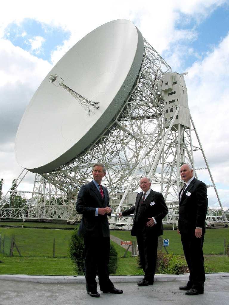
11 6 Radio telescopes They come in many shapes and sizes! A single radio telescope is usually called an antenna A collection of antennas may be operated together to form an array (e.g. MERLIN, VLA, EVN, VLBA, ALMA...) The most common type of antenna is the steerable parabolic dish (but not used for LOFAR!)

12 Figure 2: Karl Jansky s Antenna
13
14
15 A parabolic dish antenna focuses incoming radiation at the focus It is pointed at the source by steering on orthogonal axes, on either an azimuth/elevation or polar (HA, DEC) mount. The size of the dish (diameter, D) determines both the resolution and the sensitivity Resolution is given by the diffraction limit: θ λ/d so radio telescopes must be big! Point-source response is known as the beam - its size is the beamwidth
16 Sensitivity determined by the collecting area: physical area but must have sufficient surface accuracy: λ/20 Figure of merit is the telescope gain, g which quantifies the amount of radio noise power received from a source of unit flux density: units K/Jy. (see next section...) The gain is often a function of elevation, since there may be elevation-dependent gravitational deformations of the parabolic surface. Example: Effelsberg 100m diameter radio telescope wavelength 50cm 6cm 3mm beam FWHM " gain K/Jy
17 7 Radio receivers - the feed Radio photons of energy hν are too weak to do anything useful! EM-wave electric field oscillations can induce voltage oscillations in a conductor In a radio telescope this process happens at the antenna focus in a device called the feed. The simplest sort of feed is a linear dipole, which responds to E-field oscillations in a single plane. Other feeds may respond to a circular polarization mode. The output of a feed is a noise voltage, representing noise power from the radio source. By comparison with the Johnson noise from a resistor of temperature T (power = kt per unit bandwidth), the noise power s measured in kelvins, K, and is referred to as the antenna temperature, T a
18 For the Effelsberg telescope at 5 GHz (6cm) the antenna temperature from a 1 Jy source is 1.5 K. For a VLBA (25m) antenna it is 0.14 K. Since the E-field is a (2D) vector, and the induced voltage is a scalar, clearly 2 feed channels are needed to completely sample the field. This is then a dual-polarization feed. Note that a feed responds to the radiation at a single point in the focal plane - we are measuring the signal for a single pixel! Focal plane feed arrays exist, but are rare. For azimuth/elevation ( alt/az ) mounted telescopes the angle of the feed with respect to the radio source changes with HA by the parallactic angle.
19 8 Description of noise The induced voltage has characteristics which mimic the properties of (one component of) the E-field. We can describe the noise signal voltage as the sum of sinusoidal oscillations at all frequencies within the observing band, each with arbitrary relative phase. We characterise this by the centre frequency, the radio frequency or RF and the bandwidth, b. For a time shorter than 1/b the voltage behaves like a pure single frequency at RF. After a time longer than 1/b the signal phase has changed arbitrarily (due to relative rotation across the band of the individual component frequencies).
20 The antenna noise power, T a, averaged for a time t has noise fluctuations T a / (tb) Note that this is a fundamental limit to the achievable signalto-noise ratio. It is equivalent to (but not the same as) photon counting noise in other domains. A typical bandwidth may be 100 MHz; note that at 5 GHz this is only 2 percent of the band.
21 9 Receivers: amplification The induced voltage is in general too faint to detect directly. The voltage is amplified to achieve a detectable level. Note that the noise power fluctuations are also amplified by the same amount. The amplifier adds its own noise! This is usually much greater than the signal noise we are trying to detect. Radio astronomers therefore need low noise amplifiers.
22 For the Effelsberg telescope at 5 GHz the voltage noise after amplification (and after other spurious sources of noise have crept in) is equivalent to adding a further 30 K before amplification! The average noise power is now α (T a + 30) K The fluctuations are now α (T a + 30)/ (tb) K The signal-to-noise ratio is degraded by a factor T a /(T a + 30) Further electronic stages generally do not add significantly to the (already amplified) noise. The sum total of all the noise contributions is referred to as the system temperature, T sys. The quantity T sys /g is a measure of the combined sensitivity performance of the antenna and the receiving system and is called the system equivalent flux density or SEFD.
23 10 Receivers: mixing and detection For most observing frequencies, further electronic manipulation is more conveniently performed at lower frequencies. We use heterodyne systems in which the RF signal is mixed with a pure frequency tone, the local oscillator, LO. The output difference frequency is called the intermediate frequency or IF, typically centred around 150 MHz or 500 MHz. The noise characteristics of the IF signal preserve those of the input RF signal, but contain a phase-shift due to the phase of the LO signal. The IF voltage signals can be transmitted over long distances via low-loss cables, e.g. from the focus cabin to the observing room on the ground. From here on the processing depends strongly on the type of observation being made.
24 For single dish observations one may simply wish to measure the source average noise power. This is performed by passing the IF signal into a square-law detector. The output measures the mean total noise power with fluctuations producing a thermal noise error (in Jy) given by: SEFD/ (tb) As the output is the sum of source and other contributions, however, it is necessary to compare an on-source measurement with an off-source measurement. But this is not the subject of this school!
25 11 Signals for Interferometry Leading into the next lecture... For interferometry one wishes to cause interference between the IF voltage signals from 2 or more antennas. This mimics in electronics the results one would have by causing interference between the radio waves arriving at those antennas. The IF signals from different antennas are transported to a correlator, using cables, waveguides (VLA), radio-links (MER- LIN) or optical fibres. Note that signals from a common noise source can only produce interference provided that their path difference is less than 1/b
26 For very robust transmission it is necessary to digitize the signal using samplers. These sample the signal at the Nyquist rate (1/2b) and represent it at various levels of crudity: 1-bit, 2-bit,... For very long distances between the antennas (VLBI) one can then record the signals at each antenna on magnetic tape or disk, together with a time stamp to identify each bit. This permits off-line replay of the signals from the various antennas after they have been transported to the correlator. (This can be by air, sea, truck or internet!) Do not ask where the photons are...
27 Note that for dual-polarization observations the whole amplification, mixing and digitization chain will be duplicated, resulting in 2 signals (e.g LHC and RHC polarization) which need to be correlated with their counterparts from other antennas. Sometimes the IF signal band is divided into further sub-bands for separate digitization and correlation. These are loosely referred to as separate IFs in the AIPS world.
28 12 Radio disturbances radio interference: Radio source signals are extraordinarily weak compared with most man-made signals, and cannot normally be detected when the latter are present in the band. Radio astronomers are constrained to observe in narrow bands more-or-less reserved for them by international agreement.
29 the troposphere causes: absorption of the radio signal, increasing at higher frequencies. corresponding thermal emission creating an unwanted addition to T a an extra path delay of 2 m at the zenith with spatial and temporal variations the ionosphere produces: an extra (highly unpredictable) path delay proportional to λ 2 a barrier for radio waves at frequencies below 10 MHz Faraday rotation for frequencies below 1 GHz
Very Long Baseline Interferometry. Richard Porcas Max-Planck-Institut fuer Radioastronomie, Bonn
 Very Long Baseline Interferometry Richard Porcas Max-Planck-Institut fuer Radioastronomie, Bonn 1 Contents Introduction Principles and Practice of VLBI High angular resolution of long baselines The geophysics
Introduction to Radio Astronomy!
 Introduction to Radio Astronomy! Sources of radio emission! Radio telescopes - collecting the radiation! Processing the radio signal! Radio telescope characteristics! Observing radio sources Sources of
More Radio Astronomy
 More Radio Astronomy Radio Telescopes - Basic Design A radio telescope is composed of: - a radio reflector (the dish) - an antenna referred to as the feed on to which the radiation is focused - a radio
Very Long Baseline Interferometry
 Very Long Baseline Interferometry Cormac Reynolds, JIVE European Radio Interferometry School, Bonn 12 Sept. 2007 VLBI Arrays EVN (Europe, China, South Africa, Arecibo) VLBA (USA) EVN + VLBA coordinate
Signal Flow & Radiometer Equation. Aletha de Witt AVN-Newton Fund/DARA 2018 Observational & Technical Training HartRAO
 Signal Flow & Radiometer Equation Aletha de Witt AVN-Newton Fund/DARA 2018 Observational & Technical Training HartRAO Understanding Radio Waves The meaning of radio waves How radio waves are created -
Fundamentals of Radio Astronomy. Lyle Hoffman, Lafayette College ALFALFA Undergraduate Workshop Arecibo Observatory, 2008 Jan. 13
 Fundamentals of Radio Astronomy Lyle Hoffman, Lafayette College ALFALFA Undergraduate Workshop Arecibo Observatory, 2008 Jan. 13 Outline Sources in brief Radiotelescope components Radiotelescope characteristics
Phased Array Feeds & Primary Beams
 Phased Array Feeds & Primary Beams Aidan Hotan ASKAP Deputy Project Scientist 3 rd October 2014 CSIRO ASTRONOMY AND SPACE SCIENCE Outline Review of parabolic (dish) antennas. Focal plane response to a
What does reciprocity mean
 Antennas Definition of antenna: A device for converting electromagnetic radiation in space into electrical currents in conductors or vice-versa. Radio telescopes are antennas Reciprocity says we can treat
Antennas. Greg Taylor. University of New Mexico Spring Astronomy 423 at UNM Radio Astronomy
 Antennas Greg Taylor University of New Mexico Spring 2011 Astronomy 423 at UNM Radio Astronomy Radio Window 2 spans a wide range of λ and ν from λ ~ 0.33 mm to ~ 20 m! (ν = 1300 GHz to 15 MHz ) Outline
Practical Radio Interferometry VLBI. Olaf Wucknitz.
 Practical Radio Interferometry VLBI Olaf Wucknitz wucknitz@astro.uni-bonn.de Bonn, 1 December 2010 VLBI Need for long baselines What defines VLBI? Techniques VLBI science Practical issues VLBI arrays how
A Crash Course in Radio Astronomy and Interferometry: 1. Basic Radio/mm Astronomy
 A Crash Course in Radio Astronomy and Interferometry: 1. Basic Radio/mm Astronomy James Di Francesco National Research Council of Canada North American ALMA Regional Center Victoria (thanks to S. Dougherty,
Antennas. Greg Taylor. University of New Mexico Spring Astronomy 423 at UNM Radio Astronomy
 Antennas Greg Taylor University of New Mexico Spring 2017 Astronomy 423 at UNM Radio Astronomy Outline 2 Fourier Transforms Interferometer block diagram Antenna fundamentals Types of antennas Antenna performance
Practical Radio Interferometry VLBI. Olaf Wucknitz. Bonn, 21 November 2012
 Practical Radio Interferometry VLBI Olaf Wucknitz wucknitz@mpifr-bonn.mpg.de Bonn, 21 November 2012 VLBI Need for long baselines What defines VLBI? Techniques VLBI science Practical issues VLBI arrays
Practical Radio Interferometry VLBI. Olaf Wucknitz.
 Practical Radio Interferometry VLBI Olaf Wucknitz wucknitz@astro.uni-bonn.de Bonn, 23 November 2011 VLBI Need for long baselines What defines VLBI? Techniques VLBI science Practical issues VLBI arrays
Sources classification
 Sources classification Radiometry relates to the measurement of the energy radiated by one or more sources in any region of the electromagnetic spectrum. As an antenna, a source, whose largest dimension
The Cosmic Microwave Background Radiation B. Winstein, U of Chicago
 The Cosmic Microwave Background Radiation B. Winstein, U of Chicago Lecture #1 Lecture #2 What is it? How its anisotropies are generated? What Physics does it reveal? How it is measured. Lecture #3 Main
Astronomische Waarneemtechnieken (Astronomical Observing Techniques)
") Astronomische Waarneemtechnieken (Astronomical Observing Techniques) 7 th Lecture: 15 October 01 1. Introduction. Radio Emission 3. Observing 4. Antenna Technology 5. Receiver Technolgy 6. Back Ends 7.
Astronomische Waarneemtechnieken (Astronomical Observing Techniques) 7 th Lecture: 15 October 01 1. Introduction. Radio Emission 3. Observing 4. Antenna Technology 5. Receiver Technolgy 6. Back Ends 7.
Introduction to Radio Astronomy
 Introduction to Radio Astronomy The Visible Sky, Sagittarius Region 2 The Radio Sky 3 4 Optical and Radio can be done from the ground! 5 Outline The Discovery of Radio Waves Maxwell, Hertz and Marconi
Why Single Dish? Darrel Emerson NRAO Tucson. NAIC-NRAO School on Single-Dish Radio Astronomy. Green Bank, August 2003.
 Why Single Dish? Darrel Emerson NRAO Tucson NAIC-NRAO School on Single-Dish Radio Astronomy. Green Bank, August 2003. Why Single Dish? What's the Alternative? Comparisons between Single-Dish, Phased Array
Richard Dodson 1/28/2014 NARIT-KASI Winter School
 Goals: Technical introduction very short So what to cover? Things which are essential: How radio power is received - I How an interferometer works -II Antenna Fundamentals Black Body Radiation Brightness
EVLA System Commissioning Results
 EVLA System Commissioning Results EVLA Advisory Committee Meeting, March 19-20, 2009 Rick Perley EVLA Project Scientist t 1 Project Requirements EVLA Project Book, Chapter 2, contains the EVLA Project
Phased Array Feeds A new technology for multi-beam radio astronomy
 Phased Array Feeds A new technology for multi-beam radio astronomy Aidan Hotan ASKAP Deputy Project Scientist 2 nd October 2015 CSIRO ASTRONOMY AND SPACE SCIENCE Outline Review of radio astronomy concepts.
To print higher-resolution math symbols, click the Hi-Res Fonts for Printing button on the jsmath control panel.
 To print higher-resolution math symbols, click the Hi-Res Fonts for Printing button on the jsmath control panel. Radiometers Natural radio emission from the cosmic microwave background, discrete astronomical
Why Single Dish? Why Single Dish? Darrel Emerson NRAO Tucson
 Why Single Dish? Darrel Emerson NRAO Tucson Why Single Dish? What's the Alternative? Comparisons between Single-Dish, Phased Array & Interferometers Advantages and Disadvantages of Correlation Interferometer
THEORY OF MEASUREMENTS
 THEORY OF MEASUREMENTS Brian Mason Fifth NAIC-NRAO School on Single-Dish Radio Astronomy Arecibo, PR July 2009 OUTLINE Antenna-Sky Coupling Noise the Radiometer Equation Minimum Tsys Performance measures
Radio Interferometry. Xuening Bai. AST 542 Observational Seminar May 4, 2011
 Radio Interferometry Xuening Bai AST 542 Observational Seminar May 4, 2011 Outline Single-dish radio telescope Two-element interferometer Interferometer arrays and aperture synthesis Very-long base line
Fundamentals of Interferometry
 Fundamentals of Interferometry ERIS, Rimini, Sept 5-9 2011 Outline What is an interferometer? Basic theory Interlude: Fourier transforms for birdwatchers Review of assumptions and complications Interferometers
LOFAR: Special Issues
 Netherlands Institute for Radio Astronomy LOFAR: Special Issues John McKean (ASTRON) ASTRON is part of the Netherlands Organisation for Scientific Research (NWO) 1 Preamble http://www.astron.nl/~mckean/eris-2011-2.pdf
Introduction to Interferometry. Michelson Interferometer. Fourier Transforms. Optics: holes in a mask. Two ways of understanding interferometry
 Introduction to Interferometry P.J.Diamond MERLIN/VLBI National Facility Jodrell Bank Observatory University of Manchester ERIS: 5 Sept 005 Aim to lay the groundwork for following talks Discuss: General
IF/LO Systems for Single Dish Radio Astronomy Centimeter Wave Receivers
 IF/LO Systems for Single Dish Radio Astronomy Centimeter Wave Receivers Lisa Wray NAIC, Arecibo Observatory Abstract. Radio astronomy receivers designed to detect electromagnetic waves from faint celestial
University of Groningen. The logistic design of the LOFAR radio telescope Schakel, L.P.
 University of Groningen The logistic design of the LOFAR radio telescope Schakel, L.P. IMPORTANT NOTE: You are advised to consult the publisher's version (publisher's PDF) if you wish to cite from it.
Detector Systems. Graeme Carrad
 Detector Systems Graeme Carrad November 2011 The Basic Structure of a typical Radio Telescope Antenna Receiver Conversion Digitiser Signal Processing / Correlator They are much the same CSIRO. Radiotelescope
J/K). Nikolova
. Nikolova") Lecture 7: ntenna Noise Temperature and System Signal-to-Noise Ratio (Noise temperature. ntenna noise temperature. System noise temperature. Minimum detectable temperature. System signal-to-noise ratio.)
Lecture 7: ntenna Noise Temperature and System Signal-to-Noise Ratio (Noise temperature. ntenna noise temperature. System noise temperature. Minimum detectable temperature. System signal-to-noise ratio.)
Phased Array Feeds A new technology for wide-field radio astronomy
 Phased Array Feeds A new technology for wide-field radio astronomy Aidan Hotan ASKAP Project Scientist 29 th September 2017 CSIRO ASTRONOMY AND SPACE SCIENCE Outline Review of radio astronomy concepts
Introduction to DSTV Dish Observations. Alet de Witt AVN Technical Training 2016
 Introduction to DSTV Dish Observations Alet de Witt AVN Technical Training 2016 Outline Theory: - Radio Waves - Radio Telescope Antennas - Angular Sizes - Brightness Temperature and Antenna Temperature
Antennas & Receivers in Radio Astronomy
 Antennas & Receivers in Radio Astronomy Mark McKinnon Fifteenth Synthesis Imaging Workshop 1-8 June 2016 Purpose & Outline Purpose: describe how antenna elements can affect the quality of images produced
Why Single Dish? Darrel Emerson NRAO Tucson. NAIC-NRAO School on Single-Dish Radio Astronomy. Green Bank, August 2003.
 Why Single Dish? Darrel Emerson NRAO Tucson NAIC-NRAO School on Single-Dish Radio Astronomy. Green Bank, August 2003. Why Single Dish? What's the Alternative? Comparisons between Single-Dish, Phased Array
Spectrum. Radio. ν (Frequency)
") Preface Radio Astronomical Data Acquisition John Ball 1 These are introductory notes intended for students who know a little about physics and perhaps electrical engineering and who want to learn something
Preface Radio Astronomical Data Acquisition John Ball 1 These are introductory notes intended for students who know a little about physics and perhaps electrical engineering and who want to learn something
Antenna Fundamentals. Microwave Engineering EE 172. Dr. Ray Kwok
 Antenna Fundamentals Microwave Engineering EE 172 Dr. Ray Kwok Reference Antenna Theory and Design Warran Stutzman, Gary Thiele, Wiley & Sons (1981) Microstrip Antennas Bahl & Bhartia, Artech House (1980)
Coherent Receivers Principles Downconversion
 Coherent Receivers Principles Downconversion Heterodyne receivers mix signals of different frequency; if two such signals are added together, they beat against each other. The resulting signal contains
SKA1 low Baseline Design: Lowest Frequency Aspects & EoR Science
 SKA1 low Baseline Design: Lowest Frequency Aspects & EoR Science 1 st science Assessment WS, Jodrell Bank P. Dewdney Mar 27, 2013 Intent of the Baseline Design Basic architecture: 3-telescope, 2-system
Radio Astronomy for Amateurs. Presented by Keith Payea AG6CI
 Radio Astronomy for Amateurs Presented by Keith Payea AG6CI Outline Radio Astronomy Basics: What, How, Why How Amateurs can participate and contribute What is Radio Astronomy? The Study of the non-visible
Fundamentals of Radio Interferometry. Robert Laing (ESO)
") Fundamentals of Radio Interferometry Robert Laing (ESO) 1 ERIS 2015 Objectives A more formal approach to radio interferometry using coherence functions A complementary way of looking at the technique Simplifying
Fundamentals of Radio Interferometry Robert Laing (ESO) 1 ERIS 2015 Objectives A more formal approach to radio interferometry using coherence functions A complementary way of looking at the technique Simplifying
EVLA Scientific Commissioning and Antenna Performance Test Check List
 EVLA Scientific Commissioning and Antenna Performance Test Check List C. J. Chandler, C. L. Carilli, R. Perley, October 17, 2005 The following requirements come from Chapter 2 of the EVLA Project Book.
Guide to observation planning with GREAT
 Guide to observation planning with GREAT G. Sandell GREAT is a heterodyne receiver designed to observe spectral lines in the THz region with high spectral resolution and sensitivity. Heterodyne receivers
TSEK02: Radio Electronics Lecture 6: Propagation and Noise. Ted Johansson, EKS, ISY
 TSEK02: Radio Electronics Lecture 6: Propagation and Noise Ted Johansson, EKS, ISY 2 Propagation and Noise - Channel and antenna: not in the Razavi book - Noise: 2.3 The wireless channel The antenna Signal
Observational Astronomy
 Observational Astronomy Instruments The telescope- instruments combination forms a tightly coupled system: Telescope = collecting photons and forming an image Instruments = registering and analyzing the
Antennas and Propagation
 CMPE 477 Wireless and Mobile Networks Lecture 3: Antennas and Propagation Antennas Propagation Modes Line of Sight Transmission Fading in the Mobile Environment Introduction An antenna is an electrical
Submillimeter (continued)
") Submillimeter (continued) Dual Polarization, Sideband Separating Receiver Dual Mixer Unit The 12-m Receiver Here is where the receiver lives, at the telescope focus Receiver Performance T N (noise temperature)
Submillimeter (continued) Dual Polarization, Sideband Separating Receiver Dual Mixer Unit The 12-m Receiver Here is where the receiver lives, at the telescope focus Receiver Performance T N (noise temperature)
EVLA Memo #119 Wide-Band Sensitivity and Frequency Coverage of the EVLA and VLA L-Band Receivers
 EVLA Memo #119 Wide-Band Sensitivity and Frequency Coverage of the EVLA and VLA L-Band Receivers Rick Perley and Bob Hayward January 17, 8 Abstract We determine the sensitivities of the EVLA and VLA antennas
Receiver Performance and Comparison of Incoherent (bolometer) and Coherent (receiver) detection
 and Coherent (receiver) detection") At ev gap /h the photons have sufficient energy to break the Cooper pairs and the SIS performance degrades. Receiver Performance and Comparison of Incoherent (bolometer) and Coherent (receiver) detection
At ev gap /h the photons have sufficient energy to break the Cooper pairs and the SIS performance degrades. Receiver Performance and Comparison of Incoherent (bolometer) and Coherent (receiver) detection
Methodology for Analysis of LMR Antenna Systems
 Methodology for Analysis of LMR Antenna Systems Steve Ellingson June 30, 2010 Contents 1 Introduction 2 2 System Model 2 2.1 Receive System Model................................... 2 2.2 Calculation of
BRAND EVN EVN) Joint Research Activity in RadioNet4 Gino Tuccari & Walter Alef plus partners
 Joint Research Activity in RadioNet4 Gino Tuccari & Walter Alef plus partners") BRAND EVN (BRoad-bAND EVN) Joint Research Activity in RadioNet4 Gino Tuccari & Walter Alef plus partners EVN Observing Bands < 22GHz Today in the EVN separate receivers cover: 18 cm - L band 13 cm - S
BRAND EVN (BRoad-bAND EVN) Joint Research Activity in RadioNet4 Gino Tuccari & Walter Alef plus partners EVN Observing Bands < 22GHz Today in the EVN separate receivers cover: 18 cm - L band 13 cm - S
Comparing MMA and VLA Capabilities in the GHz Band. Socorro, NM Abstract
 Comparing MMA and VLA Capabilities in the 36-50 GHz Band M.A. Holdaway National Radio Astronomy Observatory Socorro, NM 87801 September 29, 1995 Abstract I explore the capabilities of the MMA and the VLA,
Radio Interferometers Around the World. Amy J. Mioduszewski (NRAO)
") Radio Interferometers Around the World Amy J. Mioduszewski (NRAO) A somewhat biased view of current interferometers Limited to telescopes that exist or are in the process of being built (i.e., I am not
Radio Interferometers Around the World Amy J. Mioduszewski (NRAO) A somewhat biased view of current interferometers Limited to telescopes that exist or are in the process of being built (i.e., I am not
Spectral Line Imaging
 ATNF Synthesis School 2003 Spectral Line Imaging Juergen Ott (ATNF) Juergen.Ott@csiro.au Topics Introduction to Spectral Lines Velocity Reference Frames Bandpass Calibration Continuum Subtraction Gibbs
Antennas & Propagation. CSG 250 Fall 2007 Rajmohan Rajaraman
 Antennas & Propagation CSG 250 Fall 2007 Rajmohan Rajaraman Introduction An antenna is an electrical conductor or system of conductors o Transmission - radiates electromagnetic energy into space o Reception
AVN Training HartRAO 2016
 AVN Training HartRAO 2016 Microwave 1 Overview Introduction to basic components used in microwave receivers. Performance characteristics of these components. Assembly of components into a complete microwave
Cormac Reynolds. ATNF Synthesis Imaging School, Narrabri 10 Sept. 2008
 Very Long Baseline Interferometry Cormac Reynolds ATNF 10 Sept. 2008 Outline Very brief history Data acquisition Calibration Applications Acknowledgements: C. Walker, S. Tingay What Is VLBI? VLBI: Very
Antennas and Propagation. Chapter 5
 Antennas and Propagation Chapter 5 Introduction An antenna is an electrical conductor or system of conductors Transmission - radiates electromagnetic energy into space Reception - collects electromagnetic
TSBB09 Image Sensors 2018-HT2. Image Formation Part 1
 TSBB09 Image Sensors 2018-HT2 Image Formation Part 1 Basic physics Electromagnetic radiation consists of electromagnetic waves With energy That propagate through space The waves consist of transversal
Antennas and Propagation
 Antennas and Propagation Chapter 5 Introduction An antenna is an electrical conductor or system of conductors Transmission - radiates electromagnetic energy into space Reception - collects electromagnetic
VLBI techniques and LOFAR
 GLOW interferometry school VLBI techniques and LOFAR Olaf Wucknitz wucknitz@astro.uni-bonn.de Hamburg, 2 September 2010 VLBI techniques Need for long baselines What defines VLBI? Techniques VLBI science
Sideband Smear: Sideband Separation with the ALMA 2SB and DSB Total Power Receivers
 and DSB Total Power Receivers SCI-00.00.00.00-001-A-PLA Version: A 2007-06-11 Prepared By: Organization Date Anthony J. Remijan NRAO A. Wootten T. Hunter J.M. Payne D.T. Emerson P.R. Jewell R.N. Martin
VERY LONG BASELINE INTERFEROMETRY
 VERY LONG BASELINE INTERFEROMETRY Summer Student Lecture Socorro, June 28, 2011 Adapted from 2004 Summer School Lecture and 2005, 2007, and 2009 Summer Student Lectures WHAT IS VLBI? 2 Radio interferometry
Detrimental Interference Levels at Individual LWA Sites LWA Engineering Memo RFS0012
 Detrimental Interference Levels at Individual LWA Sites LWA Engineering Memo RFS0012 Y. Pihlström, University of New Mexico August 4, 2008 1 Introduction The Long Wavelength Array (LWA) will optimally
Fundamentals of Radio Interferometry
 Fundamentals of Radio Interferometry Rick Perley, NRAO/Socorro Fourteenth NRAO Synthesis Imaging Summer School Socorro, NM Topics Why Interferometry? The Single Dish as an interferometer The Basic Interferometer
Antennas and Propagation. Chapter 5
 Antennas and Propagation Chapter 5 Introduction An antenna is an electrical conductor or system of conductors Transmission - radiates electromagnetic energy into space Reception - collects electromagnetic
Propagation effects (tropospheric and ionospheric phase calibration)
") Propagation effects (tropospheric and ionospheric phase calibration) Prof. Steven Tingay Curtin University of Technology Perth, Australia With thanks to Alan Roy (MPIfR), James Anderson (JIVE), Tasso Tzioumis
Propagation effects (tropospheric and ionospheric phase calibration) Prof. Steven Tingay Curtin University of Technology Perth, Australia With thanks to Alan Roy (MPIfR), James Anderson (JIVE), Tasso Tzioumis
REDUCTION OF ALMA DATA USING CASA SOFTWARE
 REDUCTION OF ALMA DATA USING CASA SOFTWARE Student: Nguyen Tran Hoang Supervisor: Pham Tuan Anh Hanoi, September - 2016 1 CONTENS Introduction Interferometry Scientific Target M100 Calibration Imaging
Fundamentals of Interferometry
 Fundamentals of Interferometry ERIS, Dwingeloo, Sept 8-13 2013 Outline What is an interferometer? Basic theory Interlude: Fourier transforms for birdwatchers Review of assumptions and complications Interferometers
Aperture Antennas. Reflectors, horns. High Gain Nearly real input impedance. Huygens Principle
 Antennas 97 Aperture Antennas Reflectors, horns. High Gain Nearly real input impedance Huygens Principle Each point of a wave front is a secondary source of spherical waves. 97 Antennas 98 Equivalence
Antennas and Receivers in Radio Astronomy
 Antennas and Receivers in Radio Astronomy Mark McKinnon Eleventh Synthesis Imaging Workshop Socorro, June 10-17, 2008 Outline 2 Context Types of antennas Antenna fundamentals Reflector antennas Mounts
Introduction to Radio Interferometry Sabrina Stierwalt Alison Peck, Jim Braatz, Ashley Bemis
 Introduction to Radio Interferometry Sabrina Stierwalt Alison Peck, Jim Braatz, Ashley Bemis Atacama Large Millimeter/submillimeter Array Expanded Very Large Array Robert C. Byrd Green Bank Telescope Very
Atacama Large Millimeter/submillimeter Array Expanded Very Large Array Robert C. Byrd Green Bank Telescope Very Long Baseline Array
 Atacama Large Millimeter/submillimeter Array Expanded Very Large Array Robert C. Byrd Green Bank Telescope Very Long Baseline Array Self-Calibration Ed Fomalont (NRAO) ALMA Data workshop Dec. 2, 2011 Atacama
LOFAR Long Baseline Calibration Commissioning
 LOFAR Long Baseline Calibration Commissioning anderson@mpifr-bonn.mpg.de On behalf of LOFAR and the LLBWG 1/31 No, No Fringes On Long Baseline Yet... I hate pretending to be an optimist when writing abstract
2.5.3 Antenna Temperature
 ECEn 665: Antennas and Propagation for Wireless Communications 36.5.3 Antenna Temperature We now turn to thermal noise received by an antenna. An antenna in a warm environment receives not only a signal
RECEIVER GAIN CALIBRATION FOR RADIO OBSERVATIONS AT WASEDA NASU PULSAR OBSERVATORY
 RECEIVER GAIN CALIBRATION FOR RADIO OBSERVATIONS AT WASEDA NASU PULSAR OBSERVATORY K. Niinuma 1,2, M. Kuniyoshi 3, N. Matsumura 3, K. Takefuji 1, S. Kida 1, A. Takeuchi 1, R. Nakamura 1, S. Suzuki 1, H.
Introduction to Radio Interferometry Anand Crossley Alison Peck, Jim Braatz, Ashley Bemis (NRAO)
") Introduction to Radio Interferometry Anand Crossley Alison Peck, Jim Braatz, Ashley Bemis (NRAO) Atacama Large Millimeter/submillimeter Array Expanded Very Large Array Robert C. Byrd Green Bank Telescope
Introduction to Radio Interferometry Anand Crossley Alison Peck, Jim Braatz, Ashley Bemis (NRAO) Atacama Large Millimeter/submillimeter Array Expanded Very Large Array Robert C. Byrd Green Bank Telescope
RECOMMENDATION ITU-R S.733-1* (Question ITU-R 42/4 (1990))**
)**") Rec. ITU-R S.733-1 1 RECOMMENDATION ITU-R S.733-1* DETERMINATION OF THE G/T RATIO FOR EARTH STATIONS OPERATING IN THE FIXED-SATELLITE SERVICE (Question ITU-R 42/4 (1990))** Rec. ITU-R S.733-1 (1992-1993)
Rec. ITU-R S.733-1 1 RECOMMENDATION ITU-R S.733-1* DETERMINATION OF THE G/T RATIO FOR EARTH STATIONS OPERATING IN THE FIXED-SATELLITE SERVICE (Question ITU-R 42/4 (1990))** Rec. ITU-R S.733-1 (1992-1993)
Antennas and Propagation
 Mobile Networks Module D-1 Antennas and Propagation 1. Introduction 2. Propagation modes 3. Line-of-sight transmission 4. Fading Slides adapted from Stallings, Wireless Communications & Networks, Second
TSEK02: Radio Electronics Lecture 6: Propagation and Noise. Ted Johansson, EKS, ISY
 TSEK02: Radio Electronics Lecture 6: Propagation and Noise Ted Johansson, EKS, ISY 2 Propagation and Noise - Channel and antenna: not in the Razavi book - Noise: 2.3 The wireless channel The antenna Signal
The Concept of Radio Telescope Receiver Design
 International Journal of Electronics and Communication Engineering. ISSN 0974-2166 Volume 4, Number 4 (2011), pp. 461-471 International Research Publication House http://www.irphouse.com The Concept of
Intermediate Physics PHYS102
 Intermediate Physics PHYS102 Dr Richard H. Cyburt Assistant Professor of Physics My office: 402c in the Science Building My phone: (304) 384-6006 My email: rcyburt@concord.edu My webpage: www.concord.edu/rcyburt
Heterodyne Interferometry with a Supercontinuum Local Oscillator. Pavel Gabor Vatican Observatory, 933 N Cherry Ave., Tucson AZ 85721, USA
 **Volume Title** ASP Conference Series, Vol. **Volume Number** **Author** c **Copyright Year** Astronomical Society of the Pacific Heterodyne Interferometry with a Supercontinuum Local Oscillator Pavel
James M Anderson. in collaboration with Jan Noordam and Oleg Smirnov. MPIfR, Bonn, 2006 Dec 07
 Ionospheric Calibration for Long-Baseline, Low-Frequency Interferometry in collaboration with Jan Noordam and Oleg Smirnov Page 1/36 Outline The challenge for radioastronomy Introduction to the ionosphere
(The basics of) VLBI Basics. Pedro Elosegui MIT Haystack Observatory. With big thanks to many of you, here and out there
 VLBI Basics. Pedro Elosegui MIT Haystack Observatory. With big thanks to many of you, here and out there") (The basics of) VLBI Basics Pedro Elosegui MIT Haystack Observatory With big thanks to many of you, here and out there Some of the Points Will Cover Today Geodetic radio telescopes VLBI vs GPS concept
(The basics of) VLBI Basics Pedro Elosegui MIT Haystack Observatory With big thanks to many of you, here and out there Some of the Points Will Cover Today Geodetic radio telescopes VLBI vs GPS concept
Introduction to Radioastronomy: Interferometers and Aperture Synthesis
 Introduction to Radioastronomy: Interferometers and Aperture Synthesis J.Köppen joachim.koppen@astro.unistra.fr http://astro.u-strasbg.fr/~koppen/jkhome.html Problem No.2: Angular resolution Diffraction
LOFAR - LOPES (prototype)
") LOFAR - LOPES (prototype) http://www.astro.ru.nl/lopes/ Radio emission from CRs air showers predicted by Askaryan 1962 and discovered by Jelley et al., 1965 offers the opportunity to carry out neutrino
LOFAR - LOPES (prototype) http://www.astro.ru.nl/lopes/ Radio emission from CRs air showers predicted by Askaryan 1962 and discovered by Jelley et al., 1965 offers the opportunity to carry out neutrino
KULLIYYAH OF ENGINEERING
 KULLIYYAH OF ENGINEERING DEPARTMENT OF ELECTRICAL & COMPUTER ENGINEERING ANTENNA AND WAVE PROPAGATION LABORATORY (ECE 4103) EXPERIMENT NO 3 RADIATION PATTERN AND GAIN CHARACTERISTICS OF THE DISH (PARABOLIC)
ALMA Sensitivity Metric for Science Sustainability Projects
 ALMA Memo 602 ALMA Sensitivity Metric for Science Sustainability ALMA-35.00.101.666-A-SPE 2017 01 23 Description Document Jeff Mangum (NRAO) Page 2 Change Record Revision Date Author Section/ Remarks Page
L- and S-Band Antenna Calibration Using Cass. A or Cyg. A
 L- and S-Band Antenna Calibration Using Cass. A or Cyg. A Item Type text; Proceedings Authors Taylor, Ralph E. Publisher International Foundation for Telemetering Journal International Telemetering Conference
EC ANTENNA AND WAVE PROPAGATION
 EC6602 - ANTENNA AND WAVE PROPAGATION FUNDAMENTALS PART-B QUESTION BANK UNIT 1 1. Define the following parameters w.r.t antenna: i. Radiation resistance. ii. Beam area. iii. Radiation intensity. iv. Directivity.
Spectral Line Observing
 Spectral Line Observing Ylva Pihlström, UNM Eleventh Synthesis Imaging Workshop Socorro, June 10-17, 2008 Introduction 2 Spectral line observers use many channels of width δν, over a total bandwidth Δν.
RADIOMETRIC TRACKING. Space Navigation
 RADIOMETRIC TRACKING Space Navigation October 24, 2016 D. Kanipe Space Navigation Elements SC orbit determination Knowledge and prediction of SC position & velocity SC flight path control Firing the attitude
Chapter 1 Introduction
 Wireless Information Transmission System Lab. Chapter 1 Introduction National Sun Yat-sen University Table of Contents Elements of a Digital Communication System Communication Channels and Their Wire-line
EVLA Memo 170 Determining full EVLA polarization leakage terms at C and X bands
 EVLA Memo 17 Determining full EVLA polarization leakage terms at C and s R.J. Sault, R.A. Perley August 29, 213 Introduction Polarimetric calibration of an interferometer array involves determining the
Random Phase Antenna Combining for SETI SETICon03
 Random Phase Antenna Combining for SETI SETICon03 Marko Cebokli S57UUU ABSTRACT: Since the direction from which the first ETI signal will arrive is not known in advance, it is possible to relax the phasing
Session2 Antennas and Propagation
 Wireless Communication Presented by Dr. Mahmoud Daneshvar Session2 Antennas and Propagation 1. Introduction Types of Anttenas Free space Propagation 2. Propagation modes 3. Transmission Problems 4. Fading
VLBI Post-Correlation Analysis and Fringe-Fitting
 VLBI Post-Correlation Analysis and Fringe-Fitting Michael Bietenholz With (many) Slides from George Moellenbroek and Craig Walker NRAO Calibration is important! What Is Delivered by a Synthesis Array?