In House Developments
|
|
|
- Kory Austin
- 6 years ago
- Views:
Transcription

1 In House Developments 1. Nano Profiler with Instantaneous phase shifting 2. Dual Frequency interferometer for dynamic analysis 3. Speckle shearing interferometer for subsurface defect detection 4. Stroboscopic Interferometer for Dynamic Characterization 5. Stroboscopic Phase Shifting concept Department of Mechanical and Industrial Engineering 15-Feb-11 1


2 Stroboscopic Interferometer Objective: Static, Dynamic and surface characterization of high frequency microstructures on a single tool Reliable methodology for precision measurement Application: In MEMS, Microfluidics related industries Background: Stroboscopy give the motion details in whole field compared to LDV for dynamic analysis Department of Mechanical and Industrial Engineering 15-Feb-11 2
3 Stroboscopic Interferometer MEMS Device driven in sinusoidal Signal Snap Shot of Phase motion Department of Mechanical and Industrial Engineering 15-Feb-11 3
4 Stroboscopic Interferometer Design of Micro-Mirror and Microcantilever Simulated static and dynamic behavior using Rayleigh-Ritz Method DUT Micro-mirror Department of Mechanical and Industrial Engineering 15-Feb-11 4

5 Stroboscopic Interferometer Surface Metrology Results Interferogram of the Micro Mirror Surface Roughness in Nanometers Surface metrology - surface roughness information Feedback about the specific Microfabrication process Department of Mechanical and Industrial Engineering 15-Feb-11 5

6 Stroboscopic Interferometer Static Characterization Results Comparison with the theoretical model Electro-static testing to get the details of Interferogram of tested Cantilever deflection on various voltages Department of Mechanical and Industrial Engineering 15-Feb-11 6
7 Laser Doppler Vibrometer Dynamic Testing Disadvantage : Single/ Scanning system Courtesy : Polytec Inc Not Real Time Department of Mechanical and Industrial Engineering 15-Feb-11 7


8 Stroboscopic Interferometer Department of Mechanical and Industrial Engineering 15-Feb-11 8


9 Stroboscopic Interferometer Dynamic Characterization SEM image of AFM cantilever Interferogram of AFM cantilever First Mode at 17.2 KHz Second Mode at 119 KHz detect fundamental frequency s of the structure & mode shape when its resonating. Department of Mechanical and Industrial Engineering 15-Feb-11 9
10 Stroboscopic Interferometer Stable light source Capability to strobe at higher frequency (~ 4 MHz) Quick Processing using Fourier Transform Method. Single tool to test all the static and dynamic behavior Proven Result match with other commercial devices for MEMS Testing Department of Mechanical and Industrial Engineering 15-Feb-11 10
11 MECH 691T Engineering Metrology and Measurement Systems Lecture 10 Instructor: N R Sivakumar 11
12 Outline Applications To precision Measurement Length, Dynamic Characteristics Film Thickness - Ellipsometry Introduction to NanoMetrology X-Ray Interferometry Combined Optical X-Ray Interferometry Bio Metrology Optical Coherence Tomography 12

13 Length Measurement Applications To precision Measurement Length, Angle and Dynamic Characteristics Film Thickness - Ellipsometry 13

14 Length Measurement 14
15 Vibration Measurement Laser Doppler Vibrometry laser Doppler Vibrometer detects the Doppler shift of laser light, that is scattered from a small area of the vibrating object. f The Doppler frequency shift is used to measure the d 2 / component of velocity which lies along the axis of the laser beam. As the laser light has a very high frequency W (approx x10 14 Hz), a direct demodulation of the light is not possible. Hence, interferometer is used to mix the scattered light coherently with a reference beam. The photo detector measures the intensity of the mixed light whose (beat) frequency is equal to the difference frequency between the reference and the measurement beam. Such an arrangement can be a Michelson interferometer 15
16 Vibration Measurement Michelson Interferometer 16
17 Vibration Measurement Laser Doppler Vibrometry A laser beam is divided at a beam splitter into a measurement beam and a reference beam which propagates in the arms of the interferometer. The photo detector measures the time dependant intensity I(t) at the point where the measurement and reference beams interfere. light intensity I(t) varies in a periodic manner corresponding to the vibration. f d 2 / This rate of change of phase is proportional to the velocity of vibration Photodetector Measurement 17
18 Vibration Measurement Due to the sinusoidal nature of the detector signal, the direction of the vibration is ambiguous. There are two ways to introduce a directional sensitivity: Solution 1: Introduction of an optical frequency shift into one arm of the interferometer Solution 2: Adding polarization components and an additional photo receiver. The most common form is the first solution. An acousto optic modulator ( Bragg cell) is incorporated into one arm of the interferometer. This type of interferometer is called heterodyne interferometer. 18
19 Vibration Measurement Heterodyne Interferometer 19
20 Vibration Measurement Acousto optic deflection An AOD is an acousto-optic crystal where a frequency ramp is applied to create a varying deflection angle of the diffracted light. An AOD is used to create the scan of the exposure laser beams in the raster scan systems. The AOD allows a high degree of flexibility and calibration of the beam deflection, which generates a very accurate scan. Together with an telecentric lens focus system, vibration-free scanning is achieved 20

21 Vibration Measurement Acousto optic principle Input laser Frequency F Output laser frequency (F+ F a ) Input laser angle Output laser angle depends on laser wavelength and acoustic freq. F a Acoustic frequency F a 21
22 Vibration Measurement Heterodyning Basic Layout Scanning Interference Data Acquisition 22

23 Vibration Measurement Acousto optic deflection Incoming laser beam at 632.8nm Deflected beam Acoustic wave Telecentric Lens 23
24 Vibration Measurement Laser Beam 2-Axes AOD Target Non - Mechanical Scanning 2 - axes Scanning Scanning Of Micro-structures Patent No: 09/222,731 ;09/350,901 24


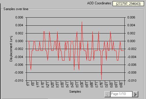


25 Vibration Measurement Ink Jet Printer head 20 m 1 Khz 20 m 10 Khz 100 Khz 2.3 mm 4.8 mm 4.8 mm 25

26 33nm Displacement in m Vibration Measurement Ink Jet Printer Head Samples over Time 26


27 Vibration Measurement AFM cantilevers 100 m 20 m 130 m 100x130x20 m cantilever vibrating at 100 khz 27
28 LDV( Laser Doppler Vibrometer) Dynamic Testing Disadvantage : Single/ Scanning system Courtesy : Polytec Inc Not Real Time
29 Stroboscopic Interferometer Static/Dynamic Testing Disadvantage : LED( Light Emitting Diode)
 in")
30 Acousto Optic Modulator (AOM) in Stroboscopy
31 Digital Laser Microinterferometer Surface Profile, Static/Dynamic Testing Speckle Pattern Interferometry limits its capability
32 Rationale & Objective Rationale: Stroboscopy give the motion details in whole field of view than point scanning like in LDV for dynamic analysis. Can be implemented for static and surface profile. But needs alternative method for strobing light and better optical processing method to measure in nano resolution. Objective: To develop a simple yet viable stroboscopic interferometer with a CW laser for comprehensive mechanical characterization of microstructures.
33 Design and fabrication of MEMS device Design of Micro-Mirror and Microcantilever Simulated static and dynamic behavior using Rayleigh-Ritz Method DUT Micro-mirror
34 Static Behavior Parameter Considered Values Length of the cantilevers (L) Thickness (h) Maximum width ( w(x)) Dielectric gap(d 0 ) Young s modulus E Density 810 m (measured) 10.5 m (measured) 90 m (measured) ~11 m (measured) GPa (values given by the manufacturer) 2320kgm -3 (values given by the manufacturer) Voltage Magnitude of Tip at 810μm deflection (nm) 55V V V 27
35 Dynamic Behavior Parameter Considered Length of the cantilevers (L) Thickness (h) Maximum width ( w(x)) Young s modulus E Density Values 350 m (measured) 1 m (measured) 35 m (measured) GPa (values given by the manufacturer) 2330kgm -3 (values given by the manufacturer) Mode Natural frequency(simulated) Natural frequency (by manufacturer) 1 st 11.2 khz 10.0 khz ~3 khz 2 nd 70.4 khz n/a
36 Schematic layout Of AOMSI M Mirror; AOM Acousto-Optic Modulator; S Spatial Filter ; L1 100mm Collimating Lens ; L2 150mm Focusing Lens; O 50mm Microscopic Objective; QW Quarter Wave Plate; L3 300mm Imaging Lens; C CCD camera; PBS Polarized Beam Splitter, P1 polarizer, S1 Stopper

37 Digital image of the layout of the AOMSI Twyman-Green interferometer assembly CCD camera Microstructure support /10 mirror Laser AOM

38 Surface Metrology Surface metrology give the surface information of the structure. Its gives the feedback of how the device is formed after the Microfabrication. Interferogram of the Micro Mirror Surface Roughness in Nanometers
39 Low-Frequency Static Characterization In Static Characterization we can conduct electro-static testing to get the details of deflection on various voltages. k E MEMS structure V DC Piezo-shaker ~
 (b) (c)")
40 Methodology (a) (b) (c)


41 Interferogram D U T
42 Deflection (m) Results Comparison of static characterization 1.4E E E E E-08 55V Exp 55V Theo 15V Exp 15V Theo 29.5 V Theo 29.5V Exp 4.0E E E E E E E E-04 Lenghth (m) Results Comparison with the theoretical model Voltage Magnitude of Tip deflection (nm) at 410 μm (Theo) Magnitude of Tip deflection (nm) (Exp) Error 55V ~3% 29.5V ~3% 15V ~9%

43 Dynamic Characterization In Dynamic Characterization we detect the fundamental frequency s of the microstructure and mode shape the structure takes when its vibrating in its resonating frequency. SEM image of AFM cantilever Interferogram of AFM cantilever
44 Methodology
 Natural frequency (provided by the manufacture) 1 st 11.2 khz 10.0 khz ~3 khz Natural frequency(ex perimental) 10.7 khz 2 nd 70.4 khz n/a 74.")
45 Sweep of frequency on the PZT stage Visualization of the Q-factor Detection of the natural frequency Detection of Natural Frequency Mode Strobing the light at that frequency to visualize high-speed motion Natural frequency(simulated) Natural frequency (provided by the manufacture) 1 st 11.2 khz 10.0 khz ~3 khz Natural frequency(ex perimental) 10.7 khz 2 nd 70.4 khz n/a 74.6 khz

46 Digital Image during Dynamic Characterization

47 Static Image of the Interferogram in dynamic conditions DUT 35 m 350 m Highly deflected portion Node Highly deflected portion
48 Mode Shape comparison at 1st Resonance frequency
49 Mode Shape comparison at 2nd Resonance frequency
50 Film Thickness - Ellipsometry Introduction Ellipsometry is an optical technique for determining properties of surfaces and thin films. The instrument analyses polarized light. (A change in the polarization upon reflection from a surface). It does not measure a film thickness, or a surface coverage, or a refractive index. Optical methods are, for this purposes, indirect methods: Information about the samples is not directly obtained, but requires calculations based on idealized models. 50

51 Film Thickness - Ellipsometry We are interested in... film thickness surface coverage refractive index of the film 51

52 Film Thickness - Ellipsometry The phenomenon of polarization Malus law I I cos 2 0 Malus law describes the angular dependence of the intensity of light emitted from two polarizers in series. The angle is between the two polarization planes. I 0 is the maximum intensity. 0 0 cos cos 0 Maximum intensity Nil intensity 52

53 Film Thickness - Ellipsometry Polarized light Linear polarized light No phase shift Superposition of two linear polarized waves 90 phase shift, equal amplitudes 53

54 Film Thickness - Ellipsometry Elliptically polarized light The polarization can be described by: ratio of amplitudes phase shift 90 phase shift, unequal amplitudes Phase shift other than 0 or 90 elliptically polarized light 54
 and Y (Psi) quantify these changes Ellipsometers measure two angles, called D (Del) and Y (Psi) tany is connected to the amplitude ratio, and D is connected to the phase shift.")
55 Film Thickness - Ellipsometry Elliptically polarized light Upon reflection the polarization will change Upon reflection from the sample surface: The amplitude ratio and/or the phase shift change D (Del) and Y (Psi) quantify these changes Ellipsometers measure two angles, called D (Del) and Y (Psi) tany is connected to the amplitude ratio, and D is connected to the phase shift. 55

56 Film Thickness - Ellipsometry Interaction of light with material When the light beam reaches the surface, some of the light is reflected and some passes into the material The law of reflection says that the angle of the incidence is equal to the angle of reflection Snell s law N 1 sin 1 N 2 sin 2 for dielectric materials k 0 n 1 sin 1 n 2 sin 2 56
57 Film Thickness - Ellipsometry Total reflection coefficients The incident beam and the reflected beam define the plane of incidence. Reflectivity. E p R the ratio of the amplitude of the outgoing wave compared to that of the incoming wave Reflectivity is calculated for linear polarized light (p- polarized or s-polarized), yielding R p and R s. P = parallel to the plane of incidence S = perpendicular to the plane of incidence E s Calculations are done with Fresnel s formulas. 57
58 Film Thickness - Ellipsometry p - WAVE E - electric vector H - magnetic vector i - incident r - reflected t - transmitted Hr Er Ei Et Ht Hi medium2 medium1 58
59 Film Thickness - Ellipsometry s - WAVE E - electric vector H - magnetic vector i - incident r - reflected t - transmitted Er Hr Hi Ht Ei Et medium2 medium1 59
60 Film Thickness - Ellipsometry The fundamental equation of ellipsometry These total reflection coefficients (R p and R s ) contain complete information on the change in polarization. tanye (id) = R p / R s (precisely measured) (calculated for a given model) 60
61 Film Thickness - Ellipsometry The fundamental equation of ellipsometry tany e (id) = R p / R s R R s p N N N 1 1 N N cos 1 N cos N cos 1 N cos N n ik 1 1 cos 2 cos 2 cos 2 cos 2 N 1 2 N 1 N 2 n=index of refraction k=extinction coefficient The complex index of refraction The incident angle The refracted angle The complex index of refraction of material 1 The complex index of refraction of material 2 n c v Speed of light in a vacuum Speed of light in a material k measures how much light is absorbed in the material and is dependent on Optical constants n and k describe how light interacts with the material 61
62 Film Thickness - Ellipsometry Apparatus Basics nulling ellipsometer Light detector Light source Polarizer Quarter wave plate (compensator) Analyzer Sample 62

63 Film Thickness - Ellipsometry Ellipsometer 63

64 Film Thickness - Ellipsometry Reflections with films Multiple interfaces If more than one interface is present, the resultant reflected beam is made up of the initially reflected beam and the infinite series of beams which are transmitted from medium 2 back into medium 1 Rp and Rs in this case are function of b, where: 2 d b N cos 2 2 the wavelength of the operation. From Rp/Rs we find the thickness of the film. 64
65 Film Thickness - Ellipsometry Examples The delta/psi domain D The lower left quadrant is where the D /Y points for a free-film material (a substrate) will be located. The film-free values for several dielectrics, metals and semiconductors are shown 65
66 Film Thickness - Ellipsometry Examples Transparent film The delta/psi trajectory for a transparent film of SiO 2 (n=1.46, k=0) on a silicon substrate. The thickness where the trajectory closes on itself is a function of the angle of incidence, a wavelength and n air and n film. For measured D and Y there is a specific thickness of the film. 66
67 Film Thickness - Ellipsometry Examples Transparent film The D /Y trajectories for transparent films with different indices of refraction on silicon. Note that there are regions where the curves are not well separated. In these regions it is hard to determine the exact index of refraction. 67
68 Film Thickness - Ellipsometry Examples lips_e.html (ellips 2.xls) Absorbing film The D /Y trajectory for a growing film of Ta on a silicon substrate. For a very thick film of an absorbing material, the delta/psi point will be characteristic of a substrate of the film material. The film-growth trajectory, therefore, is the movement from the silicon point to the tantalum point. 68

69 X-Ray Interferometry x-ray interferometry developed by Bonse and Hart Most x-ray interferometers are monolithic - single silicon Si There are 3 lamellae 800 µm thick and cut so that the faces are perpendicular to the crystal planes from which x-rays are diffracted The first is a beamsplitter, the second is a mirror and the third is an analyzer A flexure stage is machined around the analyzer lamella and a piezoelectric actuator (pzt) fitted to the side of the monolith applies a force parallel to the [220] axis, resulting in the motion of the analyzer lamella in this direction
70 X-Ray Interferometry The x-ray interferometer is aligned so that x-rays are incident on the beamsplitter at Bragg angle. Two diffracted coherent beams are produced, which are incident on the mirror lamella. Each give rise to 2 beams, and inner ones go to the analyzer fringe spacing independent of the wavelength of x-rays; but is equal to the lattice spacing of the 220 planes (0.192 nm) This interference pattern interferes with the crystal planes in the analyzer lamella to produce a Moire fringe pattern
71 X-Ray Interferometry As the analyzer lamella is moved through a distance equal to the lattice spacing, the intensity of the beam transmitted by the x-ray interferometer goes from a maximum to a minimum and back to a maximum. By measuring the x-ray intensity as the pzt moves the third lamella, one has a measure of the motion of the analyzer lamella and the instrument can be thought of as a ruler where the graduations are spaced at the distance between successive crystal planes from which x-rays are diffracted The lattice parameter is now regarded as a traceable standard of length; Consequently, measurements of displacement made using an x-ray interferometer are traceable

72 X-Ray Interferometry X-ray interferometer combined with SPM


73 X-Ray Interferometry
74 Need for Nanometrology A study conducted by the EU committee on 13 AFMs from 7 countries shows that the measurements are not consistent i.e. different machine give different result * X-ray Interferometry We need nano-scale traceability and calibration We must overcome the limit of laser wavelength 0.3nm x-ray Fringe 400nm Laser Fringe * Intercomparison of scanning probe microscopes - Journal of international societies for precision engineering and nanotechnology 74
75 Why COXI Combined Optical & X-ray Interferometer Lack of interchangeability of current nano- measuring instruments for length & dimension due to Lack of calibration ( traceability to the SI unit for length - the metre) lack of measurement standards Limit of current technology 75
76 COXI Optical Interferometry long range with limited resolution X-ray Interferometry high resolution with limited by range COXI - Compliment each other sub-nanometer accuracy over long range establish traceability to SI units for nanomeasurements 76
77 X-ray Interferometry Monolithic Silicon Crystal X-ray Source Splitter Mirror Analyser 77
78 COXI Principle and Operation X-ray Fringes nm Laser Fringes nm X-ray interferometer - accurate ruler/linear interpolator for sub fringe displacement 78

79 COXI 79

80 Optical Coherence Tomography Z=7.17 mm 500 um 80
81 Optical Coherence Tomography When using a broad band light source, acceptable visibility is obtained only for the zero th -order fringe. Lasers are used in standard interferometry However, this effect is taken to advantage in low-coherence interferometry Michelson interferometer with a low-coherence light source S If the optical path lengths from the beamsplitter to the mirrors M1 and M2 are equal, we get a bright zero-order fringe at the detector If we move M2, the fringe visibility (intensity) at the detector drops If intensities are equal (I), the intensity at the detector drops from 4I (full coherence) to 2I (no coherence) 81
82 Optical Coherence Tomography By moving M1, until the intensity again reaches maximum, the optical paths are again equal and the unknown movement of M2 is equal to the known movement of M1 This is the operating principle of LCR. Michelson interferometer with a low-coherence light source S Here the mirror M2 is replaced by the object under investigation. This technique is especially suited for measurement on semitransparent materials such as biological tissues When light beam is directed to such material, it is reflected from boundaries between different tissues of differing optical properties 82
83 Optical Coherence Tomography By a scanned motion of M1, intensity maxima at the detector are found and thereby the depth of such boundaries can be measured. This principle is analogous to ultrasound imaging which relies on measuring echoes Example of axial range measurements performed in the eye Measurement of the anterior chamber depth using low-coherence interferometry. The graph displays the magnitude of the reflected intensity as a function of distance. From Puliafito, C.A., et al. (1996) 83
84 Optical Coherence Tomography The graph shows the intensity at the detector as a function of the position of the reference mirror The intensity is a measure of the discontinuity of the optical properties of the tissue To determine the actual depth of the various boundaries, the distance between the echoes has to be multiplied by the index of refraction of the tissue Measurement of the anterior chamber depth using low-coherence interferometry. The graph displays the magnitude of the reflected intensity as a function of distance. From Puliafito, C.A., et al. (1996) 84

85 Optical Coherence Tomography This method is developed further by scanning the light in the transverse direction This technique is called optical coherence tomography (OCT) Grey scale Optical Coherence Tomography image of the anterior chamber of a human eye obtained in vivo. The image is displayed using a logarithmic mapping of the measured optical signal to brightness. From Puliafito, C.A., et al. (1996) Example of a tomographic image of the anterior chamber of the eye displayed in grey scale. The optical beam was scanned in the transverse direction and 200 axial measurements were taken 85
 239-303 Fibre-optic interferometer OCT system.")
86 Optical Coherence Tomography Fibre optic technology has made it possible to engineer compact, robust and low-cost OCT systems Schematic representation of a fibre optic version of the interferometer A F Fercher, W Drexler, C K Hitzenberger, T Lasser, Optical coherence tomography - principles and applications, Reports on progress in physics, 66 (2003) Fibre-optic interferometer OCT system. From Puliafito, C.A., et al. (1996) 86


87 OCT Images Tearney GJ, Brezinski ME, Bouma BE, et al. In vivo endoscopic optical biopsy with optical coherence tomography SCIENCE 276 (5321): JUN

88 OCT Images Drexler W, Fernandez EJ, Hermann B, et al. Adaptive optics ultrahigh resolution optical coherence tomography INVESTIGATIVE OPHTHALMOLOGY & VISUAL SCIENCE 45: U929-U Suppl. 1 APR
Module 5: Experimental Modal Analysis for SHM Lecture 36: Laser doppler vibrometry. The Lecture Contains: Laser Doppler Vibrometry
 The Lecture Contains: Laser Doppler Vibrometry Basics of Laser Doppler Vibrometry Components of the LDV system Working with the LDV system file:///d /neha%20backup%20courses%2019-09-2011/structural_health/lecture36/36_1.html
Optical coherence tomography
 Optical coherence tomography Peter E. Andersen Optics and Plasma Research Department Risø National Laboratory E-mail peter.andersen@risoe.dk Outline Part I: Introduction to optical coherence tomography
3D Optical Motion Analysis of Micro Systems. Heinrich Steger, Polytec GmbH, Waldbronn
 3D Optical Motion Analysis of Micro Systems Heinrich Steger, Polytec GmbH, Waldbronn SEMICON Europe 2012 Outline Needs and Challenges of measuring Micro Structure and MEMS Tools and Applications for optical
SENSOR+TEST Conference SENSOR 2009 Proceedings II
 B8.4 Optical 3D Measurement of Micro Structures Ettemeyer, Andreas; Marxer, Michael; Keferstein, Claus NTB Interstaatliche Hochschule für Technik Buchs Werdenbergstr. 4, 8471 Buchs, Switzerland Introduction
NEW LASER ULTRASONIC INTERFEROMETER FOR INDUSTRIAL APPLICATIONS B.Pouet and S.Breugnot Bossa Nova Technologies; Venice, CA, USA
 NEW LASER ULTRASONIC INTERFEROMETER FOR INDUSTRIAL APPLICATIONS B.Pouet and S.Breugnot Bossa Nova Technologies; Venice, CA, USA Abstract: A novel interferometric scheme for detection of ultrasound is presented.
Imaging Systems Laboratory II. Laboratory 8: The Michelson Interferometer / Diffraction April 30 & May 02, 2002
 1051-232 Imaging Systems Laboratory II Laboratory 8: The Michelson Interferometer / Diffraction April 30 & May 02, 2002 Abstract. In the last lab, you saw that coherent light from two different locations
visibility values: 1) V1=0.5 2) V2=0.9 3) V3=0.99 b) In the three cases considered, what are the values of FSR (Free Spectral Range) and
 V1=0.5 2) V2=0.9 3) V3=0.99 b) In the three cases considered, what are the values of FSR (Free Spectral Range) and") EXERCISES OF OPTICAL MEASUREMENTS BY ENRICO RANDONE AND CESARE SVELTO EXERCISE 1 A CW laser radiation (λ=2.1 µm) is delivered to a Fabry-Pérot interferometer made of 2 identical plane and parallel mirrors
EXERCISES OF OPTICAL MEASUREMENTS BY ENRICO RANDONE AND CESARE SVELTO EXERCISE 1 A CW laser radiation (λ=2.1 µm) is delivered to a Fabry-Pérot interferometer made of 2 identical plane and parallel mirrors
1.6 Beam Wander vs. Image Jitter
 8 Chapter 1 1.6 Beam Wander vs. Image Jitter It is common at this point to look at beam wander and image jitter and ask what differentiates them. Consider a cooperative optical communication system that
Fiber Pigtailed Variable Frequency Shifters Acousto-optic products
 Fiber Pigtailed Variable Frequency Shifters Acousto-optic products Introduction Frequency Shift LASER DOPPLER VIBROMETER (LDV) 3- PHYSICAL PRINCIPLES MAIN EQUATIONS An RF signal applied to a piezo-electric
R.B.V.R.R. WOMEN S COLLEGE (AUTONOMOUS) Narayanaguda, Hyderabad.
 Narayanaguda, Hyderabad.") R.B.V.R.R. WOMEN S COLLEGE (AUTONOMOUS) Narayanaguda, Hyderabad. DEPARTMENT OF PHYSICS QUESTION BANK FOR SEMESTER III PAPER III OPTICS UNIT I: 1. MATRIX METHODS IN PARAXIAL OPTICS 2. ABERATIONS UNIT II
R.B.V.R.R. WOMEN S COLLEGE (AUTONOMOUS) Narayanaguda, Hyderabad. DEPARTMENT OF PHYSICS QUESTION BANK FOR SEMESTER III PAPER III OPTICS UNIT I: 1. MATRIX METHODS IN PARAXIAL OPTICS 2. ABERATIONS UNIT II
Underwater Acoustics Research
 Underwater Acoustics Research Laser Vibrometry Applications to Underwater Sound Field Measurements Paul Lepper & Simon Dible Senior Research Fellow Applied Signal Processing Group Loughborough University
Absolute distance interferometer in LaserTracer geometry
 Absolute distance interferometer in LaserTracer geometry Corresponding author: Karl Meiners-Hagen Abstract 1. Introduction 1 In this paper, a combination of variable synthetic and two-wavelength interferometry
2. Pulsed Acoustic Microscopy and Picosecond Ultrasonics
 1st International Symposium on Laser Ultrasonics: Science, Technology and Applications July 16-18 2008, Montreal, Canada Picosecond Ultrasonic Microscopy of Semiconductor Nanostructures Thomas J GRIMSLEY
Installation and Characterization of the Advanced LIGO 200 Watt PSL
 Installation and Characterization of the Advanced LIGO 200 Watt PSL Nicholas Langellier Mentor: Benno Willke Background and Motivation Albert Einstein's published his General Theory of Relativity in 1916,
Development of C-Mod FIR Polarimeter*
 Development of C-Mod FIR Polarimeter* P.XU, J.H.IRBY, J.BOSCO, A.KANOJIA, R.LECCACORVI, E.MARMAR, P.MICHAEL, R.MURRAY, R.VIEIRA, S.WOLFE (MIT) D.L.BROWER, W.X.DING (UCLA) D.K.MANSFIELD (PPPL) *Supported
Vibration-compensated interferometer for measuring cryogenic mirrors
 Vibration-compensated interferometer for measuring cryogenic mirrors Chunyu Zhao and James H. Burge Optical Sciences Center, University of Arizona, 1630 E. University Blvd, Tucson, AZ 85721 Abstract An
attosnom I: Topography and Force Images NANOSCOPY APPLICATION NOTE M06 RELATED PRODUCTS G
 APPLICATION NOTE M06 attosnom I: Topography and Force Images Scanning near-field optical microscopy is the outstanding technique to simultaneously measure the topography and the optical contrast of a sample.
LOS 1 LASER OPTICS SET
 LOS 1 LASER OPTICS SET Contents 1 Introduction 3 2 Light interference 5 2.1 Light interference on a thin glass plate 6 2.2 Michelson s interferometer 7 3 Light diffraction 13 3.1 Light diffraction on a
Outline: Introduction: What is SPM, history STM AFM Image treatment Advanced SPM techniques Applications in semiconductor research and industry
 1 Outline: Introduction: What is SPM, history STM AFM Image treatment Advanced SPM techniques Applications in semiconductor research and industry 2 Back to our solutions: The main problem: How to get nm
(51) Int Cl.: G01B 9/02 ( ) G01B 11/24 ( ) G01N 21/47 ( )
 Int Cl.: G01B 9/02 ( ) G01B 11/24 ( ) G01N 21/47 ( )") (19) (12) EUROPEAN PATENT APPLICATION (11) EP 1 939 581 A1 (43) Date of publication: 02.07.2008 Bulletin 2008/27 (21) Application number: 07405346.3 (51) Int Cl.: G01B 9/02 (2006.01) G01B 11/24 (2006.01)
(19) (12) EUROPEAN PATENT APPLICATION (11) EP 1 939 581 A1 (43) Date of publication: 02.07.2008 Bulletin 2008/27 (21) Application number: 07405346.3 (51) Int Cl.: G01B 9/02 (2006.01) G01B 11/24 (2006.01)
Lab Report 3: Speckle Interferometry LIN PEI-YING, BAIG JOVERIA
 Lab Report 3: Speckle Interferometry LIN PEI-YING, BAIG JOVERIA Abstract: Speckle interferometry (SI) has become a complete technique over the past couple of years and is widely used in many branches of
CHAPTER 5 FINE-TUNING OF AN ECDL WITH AN INTRACAVITY LIQUID CRYSTAL ELEMENT
 CHAPTER 5 FINE-TUNING OF AN ECDL WITH AN INTRACAVITY LIQUID CRYSTAL ELEMENT In this chapter, the experimental results for fine-tuning of the laser wavelength with an intracavity liquid crystal element
J. C. Wyant Fall, 2012 Optics Optical Testing and Testing Instrumentation
 J. C. Wyant Fall, 2012 Optics 513 - Optical Testing and Testing Instrumentation Introduction 1. Measurement of Paraxial Properties of Optical Systems 1.1 Thin Lenses 1.1.1 Measurements Based on Image Equation
Theory and Applications of Frequency Domain Laser Ultrasonics
 1st International Symposium on Laser Ultrasonics: Science, Technology and Applications July 16-18 2008, Montreal, Canada Theory and Applications of Frequency Domain Laser Ultrasonics Todd W. MURRAY 1,
Lecture 20: Optical Tools for MEMS Imaging
 MECH 466 Microelectromechanical Systems University of Victoria Dept. of Mechanical Engineering Lecture 20: Optical Tools for MEMS Imaging 1 Overview Optical Microscopes Video Microscopes Scanning Electron
Modal analysis: a comparison between Finite Element Analysis (FEA) and practical Laser Doppler Vibrometer (LDV) testing.
 and practical Laser Doppler Vibrometer (LDV) testing.") 2017 UKSim-AMSS 19th International Conference on Modelling & Simulation Modal analysis: a comparison between Finite Element Analysis (FEA) and practical Laser Doppler Vibrometer (LDV) testing. Luca Pagano
2017 UKSim-AMSS 19th International Conference on Modelling & Simulation Modal analysis: a comparison between Finite Element Analysis (FEA) and practical Laser Doppler Vibrometer (LDV) testing. Luca Pagano
MICROMACHINED INTERFEROMETER FOR MEMS METROLOGY
 MICROMACHINED INTERFEROMETER FOR MEMS METROLOGY Byungki Kim, H. Ali Razavi, F. Levent Degertekin, Thomas R. Kurfess G.W. Woodruff School of Mechanical Engineering, Georgia Institute of Technology, Atlanta,
EE119 Introduction to Optical Engineering Spring 2003 Final Exam. Name:
 EE119 Introduction to Optical Engineering Spring 2003 Final Exam Name: SID: CLOSED BOOK. THREE 8 1/2 X 11 SHEETS OF NOTES, AND SCIENTIFIC POCKET CALCULATOR PERMITTED. TIME ALLOTTED: 180 MINUTES Fundamental
Comparison of resolution specifications for micro- and nanometer measurement techniques
 P4.5 Comparison of resolution specifications for micro- and nanometer measurement techniques Weckenmann/Albert, Tan/Özgür, Shaw/Laura, Zschiegner/Nils Chair Quality Management and Manufacturing Metrology
Physics 431 Final Exam Examples (3:00-5:00 pm 12/16/2009) TIME ALLOTTED: 120 MINUTES Name: Signature:
 TIME ALLOTTED: 120 MINUTES Name: Signature:") Physics 431 Final Exam Examples (3:00-5:00 pm 12/16/2009) TIME ALLOTTED: 120 MINUTES Name: PID: Signature: CLOSED BOOK. TWO 8 1/2 X 11 SHEET OF NOTES (double sided is allowed), AND SCIENTIFIC POCKET CALCULATOR
Physics 431 Final Exam Examples (3:00-5:00 pm 12/16/2009) TIME ALLOTTED: 120 MINUTES Name: PID: Signature: CLOSED BOOK. TWO 8 1/2 X 11 SHEET OF NOTES (double sided is allowed), AND SCIENTIFIC POCKET CALCULATOR
Development of innovative fringe locking strategies for vibration-resistant white light vertical scanning interferometry (VSI)
") Development of innovative fringe locking strategies for vibration-resistant white light vertical scanning interferometry (VSI) Liang-Chia Chen 1), Abraham Mario Tapilouw 1), Sheng-Lih Yeh 2), Shih-Tsong
Development of innovative fringe locking strategies for vibration-resistant white light vertical scanning interferometry (VSI) Liang-Chia Chen 1), Abraham Mario Tapilouw 1), Sheng-Lih Yeh 2), Shih-Tsong
la. Smith and C.P. Burger Department of Mechanical Engineering Texas A&M University College Station Tx
 INJECTION LOCKED LASERS AS SURF ACE DISPLACEMENT SENSORS la. Smith and C.P. Burger Department of Mechanical Engineering Texas A&M University College Station Tx. 77843 INTRODUCTION In an age where engineered
Tutorial: 3D Scanning Vibrometry for. IMAC XXVII D. E. Oliver, Polytec, Inc.
 Tutorial: 3D Scanning Vibrometry for Structural Dynamics Measurements IMAC XXVII D. E. Oliver, Polytec, Inc. Content Principles of Laser Doppler Vibrometry Scanning Laser Doppler Vibrometry (SLDV) Limitations
University of Huddersfield Repository
 University of Huddersfield Repository Gao, F., Muhamedsalih, Hussam and Jiang, Xiang In process fast surface measurement using wavelength scanning interferometry Original Citation Gao, F., Muhamedsalih,
Basics of INTERFEROMETRY
 Basics of INTERFEROMETRY P Hariharan CSIRO Division of Applied Sydney, Australia Physics ACADEMIC PRESS, INC. Harcourt Brace Jovanovich, Publishers Boston San Diego New York London Sydney Tokyo Toronto
MEMS for RF, Micro Optics and Scanning Probe Nanotechnology Applications
 MEMS for RF, Micro Optics and Scanning Probe Nanotechnology Applications Part I: RF Applications Introductions and Motivations What are RF MEMS? Example Devices RFIC RFIC consists of Active components
some aspects of Optical Coherence Tomography
 some aspects of Optical Coherence Tomography SSOM Lectures, Engelberg 17.3.2009 Ch. Meier 1 / 34 Contents 1. OCT - basic principles (Time Domain Frequency Domain) 2. Performance and limiting factors 3.
Stability of a Fiber-Fed Heterodyne Interferometer
 Stability of a Fiber-Fed Heterodyne Interferometer Christoph Weichert, Jens Flügge, Paul Köchert, Rainer Köning, Physikalisch Technische Bundesanstalt, Braunschweig, Germany; Rainer Tutsch, Technische
Basics of INTERFEROMETRY
 Basics of INTERFEROMETRY Second Edition P. HARIHARAN School ofphysics, Sydney, Australia University of Sydney CPi AMSTERDAM BOSTON HEIDELBERG LONDON NEW YORK OXFORD PARIS SAN DIEGO SAN FRANCISCO SINGAPORE
Optical Signal Processing
 Optical Signal Processing ANTHONY VANDERLUGT North Carolina State University Raleigh, North Carolina A Wiley-Interscience Publication John Wiley & Sons, Inc. New York / Chichester / Brisbane / Toronto
Optical Characterization and Defect Inspection for 3D Stacked IC Technology
 Minapad 2014, May 21 22th, Grenoble; France Optical Characterization and Defect Inspection for 3D Stacked IC Technology J.Ph.Piel, G.Fresquet, S.Perrot, Y.Randle, D.Lebellego, S.Petitgrand, G.Ribette FOGALE
648. Measurement of trajectories of piezoelectric actuators with laser Doppler vibrometer
 648. Measurement of trajectories of piezoelectric actuators with laser Doppler vibrometer V. Grigaliūnas, G. Balčiūnas, A.Vilkauskas Kaunas University of Technology, Kaunas, Lithuania E-mail: valdas.grigaliunas@ktu.lt
SCANNING LASER VIBROMETRY FOR DETECTION NOISE SOURCES WITH HIGH SPATIAL RESOLUTION
 SCANNING LASER VIBROMETRY FOR DETECTION NOISE SOURCES WITH HIGH SPATIAL RESOLUTION Dipl.-Ing (FH) Sven Frank, Dr. Jochen Schell, Dr. Reinhard Behrendt Polytec GmbH, Polytec-Platz 1-7, D-76337 Waldbronn,
Chapter Ray and Wave Optics
 109 Chapter Ray and Wave Optics 1. An astronomical telescope has a large aperture to [2002] reduce spherical aberration have high resolution increase span of observation have low dispersion. 2. If two
Experimental Competition
 37 th International Physics Olympiad Singapore 8 17 July 2006 Experimental Competition Wed 12 July 2006 Experimental Competition Page 2 List of apparatus and materials Label Component Quantity Label Component
Microscopic Laser Doppler Vibrometer
 Microscopic Laser Doppler Vibrometer System Configuration - 1 PC Controller (APU-Analog processing unit, DPU-Digital processing unit) Optic Head (MEMS Type, XS Type) Function Generator Power Supply Testing
7 CHAPTER 7: REFRACTIVE INDEX MEASUREMENTS WITH COMMON PATH PHASE SENSITIVE FDOCT SETUP
 7 CHAPTER 7: REFRACTIVE INDEX MEASUREMENTS WITH COMMON PATH PHASE SENSITIVE FDOCT SETUP Abstract: In this chapter we describe the use of a common path phase sensitive FDOCT set up. The phase measurements
Optics and Lasers. Matt Young. Including Fibers and Optical Waveguides
 Matt Young Optics and Lasers Including Fibers and Optical Waveguides Fourth Revised Edition With 188 Figures Springer-Verlag Berlin Heidelberg New York London Paris Tokyo Hong Kong Barcelona Budapest Contents
Laser Telemetric System (Metrology)
") Laser Telemetric System (Metrology) Laser telemetric system is a non-contact gauge that measures with a collimated laser beam (Refer Fig. 10.26). It measure at the rate of 150 scans per second. It basically
Laser Telemetric System (Metrology) Laser telemetric system is a non-contact gauge that measures with a collimated laser beam (Refer Fig. 10.26). It measure at the rate of 150 scans per second. It basically
SUPPLEMENTARY INFORMATION
 Optically reconfigurable metasurfaces and photonic devices based on phase change materials S1: Schematic diagram of the experimental setup. A Ti-Sapphire femtosecond laser (Coherent Chameleon Vision S)
ULTRASONIC TRANSDUCER PEAK-TO-PEAK OPTICAL MEASUREMENT
 ULTRASONIC TRANSDUCER PEAK-TO-PEAK OPTICAL MEASUREMENT Pavel SKARVADA 1, Pavel TOFEL 1, Pavel TOMANEK 1 1 Department of Physics, Faculty of Electrical Engineering and Communication, Brno University of
Department of Electrical Engineering and Computer Science
 MASSACHUSETTS INSTITUTE of TECHNOLOGY Department of Electrical Engineering and Computer Science 6.161/6637 Practice Quiz 2 Issued X:XXpm 4/XX/2004 Spring Term, 2004 Due X:XX+1:30pm 4/XX/2004 Please utilize
Contouring aspheric surfaces using two-wavelength phase-shifting interferometry
 OPTICA ACTA, 1985, VOL. 32, NO. 12, 1455-1464 Contouring aspheric surfaces using two-wavelength phase-shifting interferometry KATHERINE CREATH, YEOU-YEN CHENG and JAMES C. WYANT University of Arizona,
Supplementary Figure 1. GO thin film thickness characterization. The thickness of the prepared GO thin
 Supplementary Figure 1. GO thin film thickness characterization. The thickness of the prepared GO thin film is characterized by using an optical profiler (Bruker ContourGT InMotion). Inset: 3D optical
Surface Finish Measurement Methods and Instrumentation
 125 years of innovation Surface Finish Measurement Methods and Instrumentation Contents Visual Inspection Surface Finish Comparison Plates Contact Gauges Inductive / Variable Reluctance (INTRA) Piezo Electric
Experiment 1: Fraunhofer Diffraction of Light by a Single Slit
 Experiment 1: Fraunhofer Diffraction of Light by a Single Slit Purpose 1. To understand the theory of Fraunhofer diffraction of light at a single slit and at a circular aperture; 2. To learn how to measure
Infrared broadband 50%-50% beam splitters for s- polarized light
 University of New Orleans ScholarWorks@UNO Electrical Engineering Faculty Publications Department of Electrical Engineering 7-1-2006 Infrared broadband 50%-50% beam splitters for s- polarized light R.
A Laser-Based Thin-Film Growth Monitor
 TECHNOLOGY by Charles Taylor, Darryl Barlett, Eric Chason, and Jerry Floro A Laser-Based Thin-Film Growth Monitor The Multi-beam Optical Sensor (MOS) was developed jointly by k-space Associates (Ann Arbor,
Near-field Optical Microscopy
 Near-field Optical Microscopy R. Fernandez, X. Wang, N. Li, K. Parker, and A. La Rosa Physics Department Portland State University Portland, Oregon Near-Field SPIE Optics Microscopy East 2005 Group PSU
MECH 6491 Engineering Metrology and Measurement Systems. Lecture 4 Cont d. Instructor: N R Sivakumar
 MECH 6491 Engineering Metrology and Measurement Systems Lecture 4 Cont d Instructor: N R Sivakumar 1 Light Polarization In 1669, Huygens studied light through a calcite crystal observed two rays (birefringence).
Laser Speckle Reducer LSR-3000 Series
 Datasheet: LSR-3000 Series Update: 06.08.2012 Copyright 2012 Optotune Laser Speckle Reducer LSR-3000 Series Speckle noise from a laser-based system is reduced by dynamically diffusing the laser beam. A
Measurement of Surface Profile and Layer Cross-section with Wide Field of View and High Precision
 Hitachi Review Vol. 65 (2016), No. 7 243 Featured Articles Measurement of Surface Profile and Layer Cross-section with Wide Field of View and High Precision VS1000 Series Coherence Scanning Interferometer
The Lightwave Model 142 CW Visible Ring Laser, Beam Splitter, Model ATM- 80A1 Acousto-Optic Modulator, and Fiber Optic Cable Coupler Optics Project
 The Lightwave Model 142 CW Visible Ring Laser, Beam Splitter, Model ATM- 80A1 Acousto-Optic Modulator, and Fiber Optic Cable Coupler Optics Project Stephen W. Jordan Seth Merritt Optics Project PH 464
Will contain image distance after raytrace Will contain image height after raytrace
 Name: LASR 51 Final Exam May 29, 2002 Answer all questions. Module numbers are for guidance, some material is from class handouts. Exam ends at 8:20 pm. Ynu Raytracing The first questions refer to the
PHY 431 Homework Set #5 Due Nov. 20 at the start of class
 PHY 431 Homework Set #5 Due Nov. 0 at the start of class 1) Newton s rings (10%) The radius of curvature of the convex surface of a plano-convex lens is 30 cm. The lens is placed with its convex side down
Investigation of an optical sensor for small angle detection
 Investigation of an optical sensor for small angle detection usuke Saito, oshikazu rai and Wei Gao Nano-Metrology and Control Lab epartment of Nanomechanics Graduate School of Engineering, Tohoku University
Characterization of Silicon-based Ultrasonic Nozzles
 Tamkang Journal of Science and Engineering, Vol. 7, No. 2, pp. 123 127 (24) 123 Characterization of licon-based Ultrasonic Nozzles Y. L. Song 1,2 *, S. C. Tsai 1,3, Y. F. Chou 4, W. J. Chen 1, T. K. Tseng
Dynamic Phase-Shifting Microscopy Tracks Living Cells
 from photonics.com: 04/01/2012 http://www.photonics.com/article.aspx?aid=50654 Dynamic Phase-Shifting Microscopy Tracks Living Cells Dr. Katherine Creath, Goldie Goldstein and Mike Zecchino, 4D Technology
Laser Beam Analysis Using Image Processing
 Journal of Computer Science 2 (): 09-3, 2006 ISSN 549-3636 Science Publications, 2006 Laser Beam Analysis Using Image Processing Yas A. Alsultanny Computer Science Department, Amman Arab University for
TALKACTIVE CONTROL OF A DIFFRACTION GRATING INTERFEROMETER FOR MICROSCALE DEVICES. A Thesis Presented to. The Academic Faculty. Michael C.
 TALKACTIVE CONTROL OF A DIFFRACTION GRATING INTERFEROMETER FOR MICROSCALE DEVICES A Thesis Presented to The Academic Faculty By Michael C. Schmittdiel In Partial Fulfillment of the Requirements for the
TSBB09 Image Sensors 2018-HT2. Image Formation Part 1
 TSBB09 Image Sensors 2018-HT2 Image Formation Part 1 Basic physics Electromagnetic radiation consists of electromagnetic waves With energy That propagate through space The waves consist of transversal
High-speed wavefront control using MEMS micromirrors T. G. Bifano and J. B. Stewart, Boston University [ ] Introduction
![High-speed wavefront control using MEMS micromirrors T. G. Bifano and J. B. Stewart, Boston University [ ] Introduction](/thumbs/72/66548311.jpg "High-speed wavefront control using MEMS micromirrors T. G. Bifano and J. B. Stewart, Boston University [ ] Introduction") High-speed wavefront control using MEMS micromirrors T. G. Bifano and J. B. Stewart, Boston University [5895-27] Introduction Various deformable mirrors for high-speed wavefront control have been demonstrated
High-speed wavefront control using MEMS micromirrors T. G. Bifano and J. B. Stewart, Boston University [5895-27] Introduction Various deformable mirrors for high-speed wavefront control have been demonstrated
Holography (A13) Christopher Bronner, Frank Essenberger Freie Universität Berlin Tutor: Dr. Fidder. July 1, 2007 Experiment on July 2, 2007
 Christopher Bronner, Frank Essenberger Freie Universität Berlin Tutor: Dr. Fidder. July 1, 2007 Experiment on July 2, 2007") Holography (A13) Christopher Bronner, Frank Essenberger Freie Universität Berlin Tutor: Dr. Fidder July 1, 2007 Experiment on July 2, 2007 1 Preparation 1.1 Normal camera If we take a picture with a camera,
Holography (A13) Christopher Bronner, Frank Essenberger Freie Universität Berlin Tutor: Dr. Fidder July 1, 2007 Experiment on July 2, 2007 1 Preparation 1.1 Normal camera If we take a picture with a camera,
Computer Generated Holograms for Optical Testing
 Computer Generated Holograms for Optical Testing Dr. Jim Burge Associate Professor Optical Sciences and Astronomy University of Arizona jburge@optics.arizona.edu 520-621-8182 Computer Generated Holograms
D.C. Emmony, M.W. Godfrey and R.G. White
 A MINIATURE OPTICAL ACOUSTIC EMISSION TRANSDUCER ABSTRACT D.C. Emmony, M.W. Godfrey and R.G. White Department of Physics Loughborough University of Technology Loughborough, Leicestershire LEll 3TU United
Photonic Signals. and Systems. An Introduction. NabeelA.Riza/Ph.D. Department of Electrical and Electronic Engineering University College Cork
 Photonic Signals and Systems An Introduction NabeelA.Riza/Ph.D. Department of Electrical and Electronic Engineering University College Cork Cork, Ireland New York Chicago San Francisco Lisbon London Madrid
Measurement of Microscopic Three-dimensional Profiles with High Accuracy and Simple Operation
 238 Hitachi Review Vol. 65 (2016), No. 7 Featured Articles Measurement of Microscopic Three-dimensional Profiles with High Accuracy and Simple Operation AFM5500M Scanning Probe Microscope Satoshi Hasumura
Real-time Monitoring of Structural Vibration using Spectral-domain Optical Coherence Tomography
 Real-time Monitoring of Structural Vibration using Spectral-domain Optical Coherence Tomography Shuncong Zhong 1,2, Hao Shen 1, Yaochun Shen 1* 1 Department of Electrical Engineering and Electronics, University
This document is downloaded from DR-NTU, Nanyang Technological University Library, Singapore.
 This document is downloaded from DR-NTU, Nanyang Technological University Library, Singapore. Title Some new developments in optical dynamic testing Author(s) Fu, Yu; Phua, Poh Boon Citation Fu, Y., &
Periodic Error Correction in Heterodyne Interferometry
 Periodic Error Correction in Heterodyne Interferometry Tony L. Schmitz, Vasishta Ganguly, Janet Yun, and Russell Loughridge Abstract This paper describes periodic error in differentialpath interferometry
Advanced Nanoscale Metrology with AFM
 Advanced Nanoscale Metrology with AFM Sang-il Park Corp. SPM: the Key to the Nano World Initiated by the invention of STM in 1982. By G. Binnig, H. Rohrer, Ch. Gerber at IBM Zürich. Expanded by the invention
SUPPLEMENTARY INFORMATION DOI: /NPHOTON
 Supplementary Methods and Data 1. Apparatus Design The time-of-flight measurement apparatus built in this study is shown in Supplementary Figure 1. An erbium-doped femtosecond fibre oscillator (C-Fiber,
PHYS 3153 Methods of Experimental Physics II O2. Applications of Interferometry
 Purpose PHYS 3153 Methods of Experimental Physics II O2. Applications of Interferometry In this experiment, you will study the principles and applications of interferometry. Equipment and components PASCO
R. J. Jones College of Optical Sciences OPTI 511L Fall 2017
 R. J. Jones College of Optical Sciences OPTI 511L Fall 2017 Active Modelocking of a Helium-Neon Laser The generation of short optical pulses is important for a wide variety of applications, from time-resolved
Basic methods in imaging of micro and nano structures with atomic force microscopy (AFM)
") Basic methods in imaging of micro and nano P2538000 AFM Theory The basic principle of AFM is very simple. The AFM detects the force interaction between a sample and a very tiny tip (
Basic methods in imaging of micro and nano P2538000 AFM Theory The basic principle of AFM is very simple. The AFM detects the force interaction between a sample and a very tiny tip (
LAMB WA VB TOMOGRAPHY USING LASER-BASED ULTRASONICS
 LAMB WA VB TOMOGRAPHY USING LASER-BASED ULTRASONICS INTRODUCTION Y. Nagata, J. Huang, J. D. Achenbach and S. Krishnaswamy Center for Quality Engineering and Failure Prevention Northwestern University Evanston,
Manufacturing Metrology Team
 The Team has a range of state-of-the-art equipment for the measurement of surface texture and form. We are happy to discuss potential measurement issues and collaborative research Manufacturing Metrology
VIBROMET 500V: SINGLE POINT LASER DOPPLER VIBROMETER
 VIBROMET 500V: SINGLE POINT LASER DOPPLER VIBROMETER INTRODUCTION This paper discusses a Single Beam LDV product offered by MetroLaser; specifically it discusses the VibroMet 500V single point laser Doppler
(A) 2f (B) 2 f (C) f ( D) 2 (E) 2
 2f (B) 2 f (C) f ( D) 2 (E) 2") 1. A small vibrating object S moves across the surface of a ripple tank producing the wave fronts shown above. The wave fronts move with speed v. The object is traveling in what direction and with what
1. A small vibrating object S moves across the surface of a ripple tank producing the wave fronts shown above. The wave fronts move with speed v. The object is traveling in what direction and with what
1241. Efficiency improvement of energy harvester at higher frequencies
 24. Efficiency improvement of energy harvester at higher frequencies Giedrius Janusas, Ieva Milasauskaite 2, Vytautas Ostasevicius 3, Rolanas Dauksevicius 4 Kaunas University of Technology, Kaunas, Lithuania
Test procedures Page: 1 of 5
 Test procedures Page: 1 of 5 1 Scope This part of document establishes uniform requirements for measuring the numerical aperture of optical fibre, thereby assisting in the inspection of fibres and cables
9. Microwaves. 9.1 Introduction. Safety consideration
 MW 9. Microwaves 9.1 Introduction Electromagnetic waves with wavelengths of the order of 1 mm to 1 m, or equivalently, with frequencies from 0.3 GHz to 0.3 THz, are commonly known as microwaves, sometimes
Difrotec Product & Services. Ultra high accuracy interferometry & custom optical solutions
 Difrotec Product & Services Ultra high accuracy interferometry & custom optical solutions Content 1. Overview 2. Interferometer D7 3. Benefits 4. Measurements 5. Specifications 6. Applications 7. Cases
MEASUREMENT OF SURFACE ACOUSTIC WAVE USING AIR COUPLED TRANSDUCER AND LASER DOPPLER VIBROMETER
 21 st International Conference on Composite Materials Xi an, 20-25 th August 2017 MEASUREMENT OF SURFACE ACOUSTIC WAVE USING AIR COUPLED TRANSDUCER AND LASER DOPPLER VIBROMETER Weitao Yuan 1, Jinfeng Zhao
High stability multiplexed fibre interferometer and its application on absolute displacement measurement and on-line surface metrology
 High stability multiplexed fibre interferometer and its application on absolute displacement measurement and on-line surface metrology Dejiao Lin, Xiangqian Jiang and Fang Xie Centre for Precision Technologies,
Fabrication of Probes for High Resolution Optical Microscopy
 Fabrication of Probes for High Resolution Optical Microscopy Physics 564 Applied Optics Professor Andrès La Rosa David Logan May 27, 2010 Abstract Near Field Scanning Optical Microscopy (NSOM) is a technique
A novel tunable diode laser using volume holographic gratings
 A novel tunable diode laser using volume holographic gratings Christophe Moser *, Lawrence Ho and Frank Havermeyer Ondax, Inc. 85 E. Duarte Road, Monrovia, CA 9116, USA ABSTRACT We have developed a self-aligned
Lab 12 Microwave Optics.
 b Lab 12 Microwave Optics. CAUTION: The output power of the microwave transmitter is well below standard safety levels. Nevertheless, do not look directly into the microwave horn at close range when the
Parallel Mode Confocal System for Wafer Bump Inspection
 Parallel Mode Confocal System for Wafer Bump Inspection ECEN5616 Class Project 1 Gao Wenliang wen-liang_gao@agilent.com 1. Introduction In this paper, A parallel-mode High-speed Line-scanning confocal
INTERFEROMETRIC VIBRATION DISPLACEMENT MEASUREMENT
 Romanian Reports in Physics, Vol. 62, No. 3, P. 671 677, 2010 Dedicated to the 50 th LASER Anniversary (LASERFEST-50) INTERFEROMETRIC VIBRATION DISPLACEMENT MEASUREMENT F. GAROI 1, P.C. LOGOFATU 1, D.