MECH 6491 Engineering Metrology and Measurement Systems. Lecture 4 Cont d. Instructor: N R Sivakumar
|
|
|
- Aldous Robert Thompson
- 5 years ago
- Views:
Transcription
1 MECH 6491 Engineering Metrology and Measurement Systems Lecture 4 Cont d Instructor: N R Sivakumar 1
.")

2 Light Polarization In 1669, Huygens studied light through a calcite crystal observed two rays (birefringence). Here, we are talking about separating out different parts of light when we discuss polarization. Specifically, we are interested in the electric field of the electromagnetic wave.

3 Light Polarization Net electric field is zero Unpolarized light! Electric field only going up and down say it is linearly polarized. Light can have other types of polarizations such as circularly polarized or elliptically polarized. We will only look at linearly polarized light.
 Horizontal E z A sin( x/")
4 Plane-polarized light Vertical E y A sin( x/ t) Horizontal E z A sin( x/ t)
")
 E z A")
5 Circularly polarized light E y Right circular Ax sin( / t 90 ) E z A sin( x/ t) E y Left circular Ax sin( / t 90 ) E z A sin( x/ t)


6 Light Polarization I. Polarizers- Polarizers are made of long chained molecules which absorb light with electric fields perpendicular to the axis. Because I I E I o 2 cos 2 Malus s Law I 0 is the initial intensity, and θ i is the angle between the light's initial polarization direction and the axis of the p
7 Light Polarization II. Scattering -


8 Light Polarization III. Reflection - n sin n n n n sin n p p o p tan p 2 sin 2 cos p Brewster s Law

9 Spherical Mirrors A spherical mirror is a mirror which has the shape of a piece cut out of a spherical surface. There are two types concave, and convex mirrors. Concave mirrors magnify objects placed close to them shaving mirrors and makeup mirrors. Convex mirrors have wider fields of view passenger-side wing mirrors of cars but objects which appear in them generally look smaller (and, therefore, farther away) than they actually are.

10 Spherical Mirrors - Concave The normal to the mirror centre is called principal axis. V, at which the principal axis touches the mirror surface is called the vertex. The point C, on the principal axis, equidistant from all points on the reflecting surface of the mirror is called the centre of curvature. C to V is called the radius of curvature of the mirror R Rays parallel principal axis striking a concave mirror, are reflected by the mirror at F (between C and V) is focal point. The distance along the principal axis from the focus to the vertex is called the focal length of the mirror, and is denoted f.

11 Spherical Mirrors - Convex The definitions of the principal axis, C, R, V of a convex mirror are same as that of concave mirror. When parallel light-rays strike a convex mirror they are reflected such that they appear to emanate from a single point F located behind the mirror. This point is called the virtual focus of the mirror. The focal length f of the mirror is simply the distance between V and F. f is half of R
 An")
12 Image Formation - Concave Graphical method - just four simple rules: An incident ray // to principal axis is reflected through the focus F of the mirror An incident ray which passes through the F of the mirror is reflected // to the principal axis An incident ray which passes through the C of the mirror is reflected back along its own path (since it is normally incident on the mirror) An incident ray which strikes the mirror at V is reflected such that its angle of incidence wrt the principal axis is equal to its angle of reflection. ST is the object at distance p from the mirror (P > f). Consider 4 light rays from tip T to strike the mirror 1 is // to axis so reflects through point F. 2 is through point F so reflects // to the axis. 3 is through C so it traces its path back. 4 is towards V so it has same angles of incidence and reflectance. The point at which all these meet is where the object will be S T at distace Q (if seen further from q, the image is seen) This is a real image

13 Image Formation - Concave We only need 2 rays (minimum) to get the image position: In this case, the object ST is located within the focal length of the mirror f Consider 2 lines from tip T of the object Line 2, passes through F and reflects // to the principal axis Line 3 passes through C and is reflected along its path If these two lines are connected, the image is formed on the other side of the lens Here the image is magnified, but not inverted like the previous case There are no real light-rays behind the mirror Image cannot be viewed by projecting onto a screen This type of image is termed a virtual image The difference between a real and virtual image is, immediately after reflection from the mirror, light-rays from object converge on a real image, but diverge from a virtual image.

14 Image Formation - Convex Graphical method - just four simple rules: Incident ray // to principal axis is reflected as if it is from virtual focus F of mirror. Incident ray directed towards the virtual focus F of the mirror is reflected // to principal axis. Incident ray directed towards C of the mirror is reflected back along its own path (since it is normally incident on the mirror). Incident ray which strikes the mirror at V is reflected such that its angle of incidence wrt the principal axis is equal to its angle of reflection.. ST is the object. Consider 2 light rays from tip T to strike the mirror 1 is // to axis so appears to reflect through point F. 2 is through point C so so it traces its path back. The point of intersection of these two lines is where the image will be Vitural or Real???? Inverted and Magnified or otherwise?????
 all the lines are // and focus on the focal point F The focal")
15 Image Formation - Concave If we do this by analytical method, we will get the following formula Magnification M is given by the object and image distances It is negative if the image is inverted and positive if it is not For expression that relates the object and image distances to radius of curvature If object is far away (p = ) all the lines are // and focus on the focal point F The focal length is R/2 which can be combine to give
16 Image Formation plane mirror For plane mirrors the radius of curvature R = If R =, then f = ±R/2 = because 1/f = 0 1/p + 1/q = 1/f = 0 q = -p (which means that it is a virtual image far behind the mirror as much the object is in front) Magnification is q/p = 1 So plane mirror does not magnify or invert the image

17 Image Formation plane mirror Sign conventions may vary based on different text books. So follow consistently which ever method is used
18 Image Formation Lenses For thin lenses this distance is taken as 0

19 Image Formation Lenses A lens is a transparent medium bounded by two curved surfaces (spherical or cylindrical) Line passing normally through both bounding surfaces of a lens is called the optic axis. The point O on the optic axis midway between the two bounding surfaces is called the optic centre. There are 2 basic kinds: converging, diverging Converging lens - brings all incident light-rays parallel to its optic axis together at a point F, behind the lens, called the focal point, or focus. Diverging lens spreads out all incident light-rays parallel to its optic axis so that they appear to diverge from a virtual focal point F in front of the lens. Front side is conventionally to be the side from which the light is incident.
20 Image Formation Lenses Relationship between object and image distances to focal length is given by Magnification of the lens is given by Example (Object outside Focal Point) Object distance S = 200mm Object height h = 1mm Focal length of the lens f = 50mm Find image distance S and Magnification m
21 Image Formation Lenses Relationship between object and image distances to focal length is given by Magnification of the lens is given by Example (Object inside Focal Point) Object distance S = 30mm Object height h = 1mm Focal length of the lens f = 50mm Find image distance S and Magnification m
22 Image Formation Lenses Relationship between object and image distances to focal length is given by Magnification of the lens is given by Example (Object at Focal Point) Object distance S = 30mm Object height h = 1mm Focal length of the lens f = -50mm (diverging lens) Find image distance S and Magnification m
23 F-Number and NA The calculations used to determine lens dia are based on the concepts of focal ratio (f-number) and numerical aperture (NA). The f-number is the ratio of the lens focal length of the to its clear aperture (effective diameter ). The f-number defines the angle of the cone of light leaving the lens which ultimately forms the image. The other term used commonly in defining this cone angle is numerical aperture NA. NA is the sine of the angle made by the marginal ray with the optical axis. By using simple trigonometry, it can be seen that
24 Different Lenses


25 Spherical Aberration Spherical aberration comes from the spherical surface of a lens The further away the rays from the lens center, the bigger the error is Common in single lenses. The distance along the optical axis between the closest and farthest focal points is called (LSA) The height at which these rays is called (TSA) TSA = LSA X tan u Spherical aberration is dependent on lens shape, orientation and index of refraction of the lens Aspherical lenses offer best solution, but difficult to manufacture So cemented doublets (+ve and ve) are used to eliminate this aberration

26 Astigmatism When an off-axis object is focused by a spherical lens, the natural asymmetry leads to astigmatism. The system appears to have two different focal lengths. Saggital and tangential planes Between these conjugates, the image is either an elliptical or a circular blur. Astigmatism is defined as the separation of these conjugates. The amount of astigmatism depends on lens shape 26
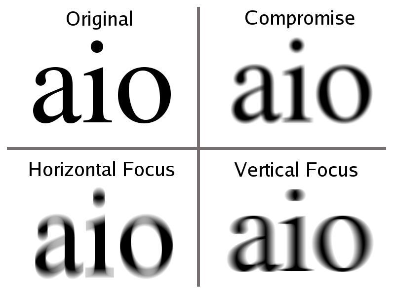
27 Astigmatism 27
28 Chromatic Aberration Material usually have different refractive indices for different wavelengths n blue >n red This is dispersion blue refracts more than the red, blue has a closer focus

29 Achromatic Doublets As in the case of spherical aberration, positive and negative elements have opposite signs of chromatic aberration. By combining elements of nearly opposite aberration to form a doublet, chromatic aberration can be partially corrected It is necessary to use two glasses with different dispersion characteristics, so that the weaker negative element can balance the aberration of the stronger, positive element.
( ) ( nb 2 nr 2)( ) R R R R 1 2 2 3")
30 Achromatic Doublets R 1 R 2 R 3 Lens maker s formula n 1 n 2 Achromatic doublet (achormat) is often used to compensate for the chromatic aberration the focuses for red and blue is the same if ( n b nr1)( ) ( nb 2 nr 2)( ) R R R R
31 MECH 691T Engineering Metrology and Measurement Systems Lecture 5 Instructor: N R Sivakumar 31
32 Outline Introduction General Description Coherence Interference between 2 plane waves Laser Doppler velocimetry Interference between spherical waves Interferometry Wavefront Division Amplitude Division Heterodyne Interferometry 32
33 Light as Waves Waves have a wavelength Waves have a frequency 33
34 Frequency Thousand (10 3 ) oscillations/second - kilohertz (khz) Million (10 6 ) oscillations/second - megahertz (MHz) Billion) (10 9 ) oscillations/second - gigahertz (GHz) Thousand billion (10 12 ) oscillations per second - terahertz (THz) Million billion) (10 15 ) oscillations per second - petahertz (PHz) 34
35 Introduction The superposition principle for electromagnetic waves implies that, two overlapping fields Ul and U2 add to give Ul + U2. This is the basis for interference. 35

36 Interference in water waves 36
37 Overlapping Semicircles 37
38 Superposition +1 Constructive Interference t t In Phase +2 t -2 38
39 Superposition +1 Destructive Interference t t Out of Phase 180 degrees +2-2 t 39
40 Superposition Different f ) Constructive 2) Destructive 3) Neither 40
41 Superposition Different f ) Constructive 2) Destructive 3) Neither 41
42 Interference Requirements Need two (or more) waves Must have same frequency Must be coherent (i.e. waves must have definite phase relation) 42
43 General Description Interference can occur when two or more waves overlap each other in space. Assume that two waves described by and overlap The electromagnetic wave theory tells us that the resulting field simply becomes the sum The observable quantity is intensity (irradiance) I which is Where e i = (cos + isin ) and 43
44 General Description Resulting intensity is not just (I 1 + I 2 ). When 2 waves interfere is called the interference term We also see that when then and I reaches minima (cos 180 ) which means destructive interference Similarly when then and I reaches maxima (cos 0 ) constructive interference When 2 waves have equal intensity I 1 = I 2 = I 0 44
45 Coherence Detection of light is an averaging process in space and time We assume that ul and u2 to have the same single frequency Light wave with a single frequency must have an infinite length However sources emitting light of a single frequency do not exist 45
46 Coherence Here we see two successive wave trains of the partial waves The two wave trains have equal amplitude and length Lc, with an abrupt, arbitrary phase difference a) shows the situation when the two waves have traveled equal paths. We see that although the phase of the original wave fluctuates randomly, the phase difference remains constant in time 46
47 Coherence In c) wave 2 has traveled Lc longer than wave 1. The head of the wave trains in wave 2 coincide with tail of the corresponding wave trains in partial wave 1. Now the phase difference fluctuates randomly as the successive wave trains pass by Here cos varies randomly between +1 and -1 and for multiple trains it becomes 0 (no interference) I = I 1 + I 2 47
48 Coherence In b) wave 2 has traveled l longer than wave 1 where 0<l<L c. For many wavetrains the phase difference varies in time proportional to we still can observe an interference pattern but with a reduced contrast is the coherence length and is the coherence time For white light, the coherence length is 1 micron 48

49 Plane Wave Interference When two plane wave interfere the resultant fringe spacing is given by 49
50 Laser Doppler Velocimetry (LDV) Method for measuring the velocity of moving objects Based on the Doppler effect light changes its frequency (wavelength) when detected by a stationary observer after being scattered from a moving object example - when the whistle from a train changes from a high to a low tone as the train passes by 50
51 Laser Doppler Velocimetry (LDV) Particle is moving in a test volume where two plane waves interfere at an angle These two waves will form interference planes which are parallel to the bisector of a and separated by a distance As the particle moves through test volume, it will scatter light when it passes a bright fringe and scatter no light while passing a dark fringe The resulting light pulses can be recorded by a detector The time lapse between pulses is t d and frequency is f d = 1/t d 51

52 Laser Doppler Velocimetry (LDV) 52
53 Laser Doppler Velocimetry (LDV) If there are many particles of different Vs many different frequencies can be recorded on a frequency analyzer and the resulting spectrum will tell how the particles are distributed among the different velocities You know, the and the f can be recorded. V can be calculated This method does not distinguish between particles moving in opposite directions LDV can be applied for measurement of the velocity of moving surfaces, turbulence in liquids and gases (where the liquid or gas seeded with particles). Examples - of stream velocities around ship propellers, velocity distributions of oil drops in IC engines 53

54 Interference between other Waves Figure shows the fringe pattern in xzplane when spherical waves from two point sources P1 and P2 on the z-axis interfere. Fringe density increases as distance between PI and P2 increases 54


55 Interference between other Waves The intensity distribution in XY plane is Where This called circular zone pattern 55
56 Interference between other Waves By measuring the distance between interference fringes over selected planes in space, quantities such as the angle and distance can be found. One further step would be to apply for a wave reflected from a rough surface By observing the interference - can determine the surface topography For smoother surfaces, however, such as optical components (lenses, mirrors, etc.) where tolerances of the order of fractions of a wavelength are to be measured, that kind of interferometry is quite common. 56
57 Interferometry Light waves interfere only if they are from the same source (why???) Most interferometers have the following elements light source element for splitting the light into two (or more) partial waves different propagation paths where the partial waves undergo different phase contributions element for superposing the partial waves detector for observation of the interference 57
58 Interferometry Depending on how the light is split, interferometers are commonly classified Wavefront division interferometers Amplitude division interferometers 58
59 Wavefront Division Example of a wavefront dividing interferometer, (Thomas Young) The incident wavefront is divided by passing through two small holes at S I and S 2 in a screen 1. The emerging spherical wavefronts from S I and S 2 will interfere, and the pattern is observed on screen 2. The path length differences of the light reaching an arbitrary point x on S 2 is found from Figure When the distance D between screens is much greater than the distance d between S 1 and S 2, we have a good approximation 59

60 Wavefront Division y m=2 m=1 m=0 m=1 m=2 D 60
61 Wavefront Division dsin m m = 0,1,2,3... Maximum tan y m D or y m Dtan Dsin y m m D d Maxima m y m +/ D /d 2D /d 3D /d m y m +/ Minima D /2d 3D /2d 5D /2d 7D /2d dsin (m 1 ) m = 0,1,2,3... Minimum 2 dsin y m (m 1/2) D d 61
62 Wavefront Division 13E Suppose that Young s experiment is performed with blue-green light of 500 nm. The slits are 1.2mm apart, and the viewing screen is 5.4 m from the slits. How far apart the bright fringes? From the table on the previous slide we see that the separation between bright fringes is D /d D /d (5.4m)( m)/0.0012m m 2.25mm 62
63 Wavefront Division A) Fresnel Biprism B) Lloyds Mirror C) Michelsons Stellar Interferometer 63
64 Amplitude Division Example of a amplitude dividing interferometer, (Michelson) Amplitude is divided by beamsplitter BS which partly reflects and partly transmits These divided light go to two mirrors M 1 and M 2 where they are reflected back. The reflected lights recombine to form interference on the detector D The path length can be varied by moving one of the mirrors or by mounting that on movable object (movement of x give path difference of 2x) and phase difference 64
65 Amplitude Division As M 2 moves the displacement is measured by counting the number of light maxima registered by D By counting the number of maxima per unit time will give the velocity of the object. The intensity distribution is given by Ezekiel, Shaoul. RES Video Demonstrations in Lasers and Optics, Spring (Massachusetts Institute of Technology: MIT OpenCourseWare), (Accessed 15 May, 2012). License: Creative Commons BY-NC-SA 65
66 Michelson Interferometer Split a beam with a Half Mirror, the use mirrors to recombine the two beams. Mirror Light sourc e Half Mirror Screen Mirror 66
67 Michelson Interferometer If the red beam goes the same length as the blue beam, then the two beams will constructively interfere and a bright spot will appear on screen. Mirror Light sourc e Half Mirror Screen Mirror 67
68 Michelson Interferometer If the blue beam goes a little extra distance, s, the the screen will show a different interference pattern. Mirror Light sourc e Half Mirror Screen s Mirror 68
69 Michelson Interferometer If s = /4, then the interference pattern changes from bright to dark. Mirror Light sourc e Half Mirror Screen s Mirror 69
70 Michelson Interferometer If s = /2, then the interference pattern changes from bright to dark back to bright (a fringe shift). Mirror Light sourc e Half Mirror Screen s Mirror 70
71 Michelson Interferometer By counting the number of fringe shifts, we can determine how far s is! Mirror Light sourc e Half Mirror Screen s Mirror 71
72 Michelson Interferometer If we use the red laser ( =632 nm), then each fringe shift corresponds to a distance the mirror moves of 316 nm (about 1/3 of a micron)! Mirror Light sourc e Half Mirror Screen s Mirror 72
73 Amplitude Division Twyman Green Interferometer Mach Zehnder Interferometer 73
74 Dual Frequency Interferometer We stated that two waves of different frequencies do not produce observable interference. By combining two plane waves The resultant intensity becomes If the frequency difference V I - V 2 is very small and constant, this variation in I with time can be detected This is utilized in the dual-frequency Michelson interferometer for length measurement Also called as Heterodyne interferometer 74
75 Dual Frequency Interferometer 75
Chapter Ray and Wave Optics
 109 Chapter Ray and Wave Optics 1. An astronomical telescope has a large aperture to [2002] reduce spherical aberration have high resolution increase span of observation have low dispersion. 2. If two
Mirrors and Lenses. Images can be formed by reflection from mirrors. Images can be formed by refraction through lenses.
 Mirrors and Lenses Images can be formed by reflection from mirrors. Images can be formed by refraction through lenses. Notation for Mirrors and Lenses The object distance is the distance from the object
R.B.V.R.R. WOMEN S COLLEGE (AUTONOMOUS) Narayanaguda, Hyderabad.
 Narayanaguda, Hyderabad.") R.B.V.R.R. WOMEN S COLLEGE (AUTONOMOUS) Narayanaguda, Hyderabad. DEPARTMENT OF PHYSICS QUESTION BANK FOR SEMESTER III PAPER III OPTICS UNIT I: 1. MATRIX METHODS IN PARAXIAL OPTICS 2. ABERATIONS UNIT II
R.B.V.R.R. WOMEN S COLLEGE (AUTONOMOUS) Narayanaguda, Hyderabad. DEPARTMENT OF PHYSICS QUESTION BANK FOR SEMESTER III PAPER III OPTICS UNIT I: 1. MATRIX METHODS IN PARAXIAL OPTICS 2. ABERATIONS UNIT II
Preview. Light and Reflection Section 1. Section 1 Characteristics of Light. Section 2 Flat Mirrors. Section 3 Curved Mirrors
 Light and Reflection Section 1 Preview Section 1 Characteristics of Light Section 2 Flat Mirrors Section 3 Curved Mirrors Section 4 Color and Polarization Light and Reflection Section 1 TEKS The student
Performance Factors. Technical Assistance. Fundamental Optics
 Performance Factors After paraxial formulas have been used to select values for component focal length(s) and diameter(s), the final step is to select actual lenses. As in any engineering problem, this
Lecture 2: Geometrical Optics. Geometrical Approximation. Lenses. Mirrors. Optical Systems. Images and Pupils. Aberrations.
 Lecture 2: Geometrical Optics Outline 1 Geometrical Approximation 2 Lenses 3 Mirrors 4 Optical Systems 5 Images and Pupils 6 Aberrations Christoph U. Keller, Leiden Observatory, keller@strw.leidenuniv.nl
Phys214 Fall 2004 Midterm Form A
 1. A clear sheet of polaroid is placed on top of a similar sheet so that their polarizing axes make an angle of 30 with each other. The ratio of the intensity of emerging light to incident unpolarized
Ch 24. Geometric Optics
 text concept Ch 24. Geometric Optics Fig. 24 3 A point source of light P and its image P, in a plane mirror. Angle of incidence =angle of reflection. text. Fig. 24 4 The blue dashed line through object
Lecture 2: Geometrical Optics. Geometrical Approximation. Lenses. Mirrors. Optical Systems. Images and Pupils. Aberrations.
 Lecture 2: Geometrical Optics Outline 1 Geometrical Approximation 2 Lenses 3 Mirrors 4 Optical Systems 5 Images and Pupils 6 Aberrations Christoph U. Keller, Leiden Observatory, keller@strw.leidenuniv.nl
Lecture 3: Geometrical Optics 1. Spherical Waves. From Waves to Rays. Lenses. Chromatic Aberrations. Mirrors. Outline
 Lecture 3: Geometrical Optics 1 Outline 1 Spherical Waves 2 From Waves to Rays 3 Lenses 4 Chromatic Aberrations 5 Mirrors Christoph U. Keller, Leiden Observatory, keller@strw.leidenuniv.nl Lecture 3: Geometrical
SUBJECT: PHYSICS. Use and Succeed.
 SUBJECT: PHYSICS I hope this collection of questions will help to test your preparation level and useful to recall the concepts in different areas of all the chapters. Use and Succeed. Navaneethakrishnan.V
always positive for virtual image
 Point to be remembered: sign convention for Spherical mirror Object height, h = always positive Always +ve for virtual image Image height h = Always ve for real image. Object distance from pole (u) = always
Lecture 21. Physics 1202: Lecture 21 Today s Agenda
 Physics 1202: Lecture 21 Today s Agenda Announcements: Team problems today Team 14: Gregory Desautels, Benjamin Hallisey, Kyle Mcginnis Team 15: Austin Dion, Nicholas Gandza, Paul Macgillis-Falcon Homework
1) An electromagnetic wave is a result of electric and magnetic fields acting together. T 1)
 An electromagnetic wave is a result of electric and magnetic fields acting together. T 1)") Exam 3 Review Name TRUE/FALSE. Write 'T' if the statement is true and 'F' if the statement is false. 1) An electromagnetic wave is a result of electric and magnetic fields acting together. T 1) 2) Electromagnetic
Exam 3 Review Name TRUE/FALSE. Write 'T' if the statement is true and 'F' if the statement is false. 1) An electromagnetic wave is a result of electric and magnetic fields acting together. T 1) 2) Electromagnetic
Projects in Optics. Applications Workbook
 Projects in Optics Applications Workbook Created by the technical staff of Newport Corporation with the assistance of Dr. Donald C. O Shea of the School of Physics at the Georgia Institute of Technology.
UNIT 12 LIGHT and OPTICS
 UNIT 12 LIGHT and OPTICS What is light? Light is simply a name for a range of electromagnetic radiation that can be detected by the human eye. What characteristic does light have? Light is electromagnetic
GIST OF THE UNIT BASED ON DIFFERENT CONCEPTS IN THE UNIT (BRIEFLY AS POINT WISE). RAY OPTICS
. RAY OPTICS") 209 GIST OF THE UNIT BASED ON DIFFERENT CONCEPTS IN THE UNIT (BRIEFLY AS POINT WISE). RAY OPTICS Reflection of light: - The bouncing of light back into the same medium from a surface is called reflection
209 GIST OF THE UNIT BASED ON DIFFERENT CONCEPTS IN THE UNIT (BRIEFLY AS POINT WISE). RAY OPTICS Reflection of light: - The bouncing of light back into the same medium from a surface is called reflection
Name. Light Chapter Summary Cont d. Refraction
 Page 1 of 17 Physics Week 12(Sem. 2) Name Light Chapter Summary Cont d with a smaller index of refraction to a material with a larger index of refraction, the light refracts towards the normal line. Also,
HUYGENS PRINCIPLE AND INTERFERENCE
 HUYGENS PRINCIPLE AND INTERFERENCE VERY SHORT ANSWER QUESTIONS Q-1. Can we perform Double slit experiment with ultraviolet light? Q-2. If no particular colour of light or wavelength is specified, then
Section A Conceptual and application type questions. 1 Which is more observable diffraction of light or sound? Justify. (1)
") INDIAN SCHOOL MUSCAT Department of Physics Class : XII Physics Worksheet - 6 (2017-2018) Chapter 9 and 10 : Ray Optics and wave Optics Section A Conceptual and application type questions 1 Which is more
INDIAN SCHOOL MUSCAT Department of Physics Class : XII Physics Worksheet - 6 (2017-2018) Chapter 9 and 10 : Ray Optics and wave Optics Section A Conceptual and application type questions 1 Which is more
Imaging Systems Laboratory II. Laboratory 8: The Michelson Interferometer / Diffraction April 30 & May 02, 2002
 1051-232 Imaging Systems Laboratory II Laboratory 8: The Michelson Interferometer / Diffraction April 30 & May 02, 2002 Abstract. In the last lab, you saw that coherent light from two different locations
Applied Optics. , Physics Department (Room #36-401) , ,
 , ,") Applied Optics Professor, Physics Department (Room #36-401) 2290-0923, 019-539-0923, shsong@hanyang.ac.kr Office Hours Mondays 15:00-16:30, Wednesdays 15:00-16:30 TA (Ph.D. student, Room #36-415) 2290-0921,
Applied Optics Professor, Physics Department (Room #36-401) 2290-0923, 019-539-0923, shsong@hanyang.ac.kr Office Hours Mondays 15:00-16:30, Wednesdays 15:00-16:30 TA (Ph.D. student, Room #36-415) 2290-0921,
Waves & Oscillations
 Physics 42200 Waves & Oscillations Lecture 33 Geometric Optics Spring 2013 Semester Matthew Jones Aberrations We have continued to make approximations: Paraxial rays Spherical lenses Index of refraction
 Light: Reflection and Refraction Light Reflection of Light by Plane Mirror Reflection of Light by Spherical Mirror Formation of Image by Mirror Sign Convention & Mirror Formula Refraction of light Through
Exam 4. Name: Class: Date: Multiple Choice Identify the choice that best completes the statement or answers the question.
 Name: Class: Date: Exam 4 Multiple Choice Identify the choice that best completes the statement or answers the question. 1. Mirages are a result of which physical phenomena a. interference c. reflection
LIGHT REFLECTION AND REFRACTION
 LIGHT REFLECTION AND REFRACTION REFLECTION OF LIGHT A highly polished surface, such as a mirror, reflects most of the light falling on it. Laws of Reflection: (i) The angle of incidence is equal to the
Algebra Based Physics. Reflection. Slide 1 / 66 Slide 2 / 66. Slide 3 / 66. Slide 4 / 66. Slide 5 / 66. Slide 6 / 66.
 Slide 1 / 66 Slide 2 / 66 Algebra Based Physics Geometric Optics 2015-12-01 www.njctl.org Slide 3 / 66 Slide 4 / 66 Table of ontents lick on the topic to go to that section Reflection Refraction and Snell's
Converging Lenses. Parallel rays are brought to a focus by a converging lens (one that is thicker in the center than it is at the edge).
.") Chapter 30: Lenses Types of Lenses Piece of glass or transparent material that bends parallel rays of light so they cross and form an image Two types: Converging Diverging Converging Lenses Parallel rays
Chapter 30: Lenses Types of Lenses Piece of glass or transparent material that bends parallel rays of light so they cross and form an image Two types: Converging Diverging Converging Lenses Parallel rays
Chapter 29/30. Wave Fronts and Rays. Refraction of Sound. Dispersion in a Prism. Index of Refraction. Refraction and Lenses
 Chapter 29/30 Refraction and Lenses Refraction Refraction the bending of waves as they pass from one medium into another. Caused by a change in the average speed of light. Analogy A car that drives off
PHYSICS FOR THE IB DIPLOMA CAMBRIDGE UNIVERSITY PRESS
 Option C Imaging C Introduction to imaging Learning objectives In this section we discuss the formation of images by lenses and mirrors. We will learn how to construct images graphically as well as algebraically.
Light and Applications of Optics
 UNIT 4 Light and Applications of Optics Topic 4.1: What is light and how is it produced? Topic 4.6: What are lenses and what are some of their applications? Topic 4.2 : How does light interact with objects
INTRODUCTION THIN LENSES. Introduction. given by the paraxial refraction equation derived last lecture: Thin lenses (19.1) = 1. Double-lens systems
 = 1. Double-lens systems") Chapter 9 OPTICAL INSTRUMENTS Introduction Thin lenses Double-lens systems Aberrations Camera Human eye Compound microscope Summary INTRODUCTION Knowledge of geometrical optics, diffraction and interference,
Chapter 9 OPTICAL INSTRUMENTS Introduction Thin lenses Double-lens systems Aberrations Camera Human eye Compound microscope Summary INTRODUCTION Knowledge of geometrical optics, diffraction and interference,
Average: Standard Deviation: Max: 99 Min: 40
 1 st Midterm Exam Average: 83.1 Standard Deviation: 12.0 Max: 99 Min: 40 Please contact me to fix an appointment, if you took less than 65. Chapter 33 Lenses and Op/cal Instruments Units of Chapter 33
LOS 1 LASER OPTICS SET
 LOS 1 LASER OPTICS SET Contents 1 Introduction 3 2 Light interference 5 2.1 Light interference on a thin glass plate 6 2.2 Michelson s interferometer 7 3 Light diffraction 13 3.1 Light diffraction on a
Experiment 1: Fraunhofer Diffraction of Light by a Single Slit
 Experiment 1: Fraunhofer Diffraction of Light by a Single Slit Purpose 1. To understand the theory of Fraunhofer diffraction of light at a single slit and at a circular aperture; 2. To learn how to measure
Chapter 18 Optical Elements
 Chapter 18 Optical Elements GOALS When you have mastered the content of this chapter, you will be able to achieve the following goals: Definitions Define each of the following terms and use it in an operational
12:40-2:40 3:00-4:00 PM
 Physics 294H l Professor: Joey Huston l email:huston@msu.edu l office: BPS3230 l Homework will be with Mastering Physics (and an average of 1 hand-written problem per week) Help-room hours: 12:40-2:40
28 Thin Lenses: Ray Tracing
 28 Thin Lenses: Ray Tracing A lens is a piece of transparent material whose surfaces have been shaped so that, when the lens is in another transparent material (call it medium 0), light traveling in medium
Chapter 23. Mirrors and Lenses
 Chapter 23 Mirrors and Lenses Notation for Mirrors and Lenses The object distance is the distance from the object to the mirror or lens Denoted by p The image distance is the distance from the image to
Exam 3--PHYS 2021M-Spring 2009
 Name: Class: Date: Exam 3--PHYS 2021M-Spring 2009 Multiple Choice Identify the choice that best completes the statement or answers the question Each question is worth 2 points 1 Images made by mirrors
Light sources can be natural or artificial (man-made)
") Light The Sun is our major source of light Light sources can be natural or artificial (man-made) People and insects do not see the same type of light - people see visible light - insects see ultraviolet
Light The Sun is our major source of light Light sources can be natural or artificial (man-made) People and insects do not see the same type of light - people see visible light - insects see ultraviolet
Section 1: Sound. Sound and Light Section 1
 Sound and Light Section 1 Section 1: Sound Preview Key Ideas Bellringer Properties of Sound Sound Intensity and Decibel Level Musical Instruments Hearing and the Ear The Ear Ultrasound and Sonar Sound
Diffraction. Interference with more than 2 beams. Diffraction gratings. Diffraction by an aperture. Diffraction of a laser beam
 Diffraction Interference with more than 2 beams 3, 4, 5 beams Large number of beams Diffraction gratings Equation Uses Diffraction by an aperture Huygen s principle again, Fresnel zones, Arago s spot Qualitative
AP Physics Problems -- Waves and Light
 AP Physics Problems -- Waves and Light 1. 1974-3 (Geometric Optics) An object 1.0 cm high is placed 4 cm away from a converging lens having a focal length of 3 cm. a. Sketch a principal ray diagram for
Chapter 23. Mirrors and Lenses
 Chapter 23 Mirrors and Lenses Mirrors and Lenses The development of mirrors and lenses aided the progress of science. It led to the microscopes and telescopes. Allowed the study of objects from microbes
Reflection! Reflection and Virtual Image!
 1/30/14 Reflection - wave hits non-absorptive surface surface of a smooth water pool - incident vs. reflected wave law of reflection - concept for all electromagnetic waves - wave theory: reflected back
Final Reg Optics Review SHORT ANSWER. Write the word or phrase that best completes each statement or answers the question.
 Final Reg Optics Review 1) How far are you from your image when you stand 0.75 m in front of a vertical plane mirror? 1) 2) A object is 12 cm in front of a concave mirror, and the image is 3.0 cm in front
PHYSICS. Chapter 35 Lecture FOR SCIENTISTS AND ENGINEERS A STRATEGIC APPROACH 4/E RANDALL D. KNIGHT
 PHYSICS FOR SCIENTISTS AND ENGINEERS A STRATEGIC APPROACH 4/E Chapter 35 Lecture RANDALL D. KNIGHT Chapter 35 Optical Instruments IN THIS CHAPTER, you will learn about some common optical instruments and
Will contain image distance after raytrace Will contain image height after raytrace
 Name: LASR 51 Final Exam May 29, 2002 Answer all questions. Module numbers are for guidance, some material is from class handouts. Exam ends at 8:20 pm. Ynu Raytracing The first questions refer to the
HOLIDAY HOME WORK PHYSICS CLASS-12B AUTUMN BREAK 2018
 HOLIDAY HOME WK PHYSICS CLASS-12B AUTUMN BREAK 2018 NOTE: 1. THESE QUESTIONS ARE FROM PREVIOUS YEAR BOARD PAPERS FROM 2009-2018 CHAPTERS EMI,AC,OPTICS(BUT TRY TO SOLVE ONLY NON-REPEATED QUESTION) QUESTION
Lecture 4: Geometrical Optics 2. Optical Systems. Images and Pupils. Rays. Wavefronts. Aberrations. Outline
 Lecture 4: Geometrical Optics 2 Outline 1 Optical Systems 2 Images and Pupils 3 Rays 4 Wavefronts 5 Aberrations Christoph U. Keller, Leiden University, keller@strw.leidenuniv.nl Lecture 4: Geometrical
OSCILLATIONS and WAVES
 OSCILLATIONS and WAVES Oscillations Oscillations are vibrations which repeat themselves. EXAMPLE: Oscillations can be driven externally, like a pendulum in a gravitational field EXAMPLE: Oscillations can
Notation for Mirrors and Lenses. Chapter 23. Types of Images for Mirrors and Lenses. More About Images
 Notation for Mirrors and Lenses Chapter 23 Mirrors and Lenses Sections: 4, 6 Problems:, 8, 2, 25, 27, 32 The object distance is the distance from the object to the mirror or lens Denoted by p The image
WHS-CH-23 Light: Geometric Optics Show all your work, equations used, and box in your answers!
 WHS-CH-23 Light: Geometric Optics Show all your work, equations used, and box in your answers! Willebrord Snell (1591-1626) Snell developed methods for measuring the Earth. He proposed the method of triangulation
Chapter 34 The Wave Nature of Light; Interference. Copyright 2009 Pearson Education, Inc.
 Chapter 34 The Wave Nature of Light; Interference 34-7 Luminous Intensity The intensity of light as perceived depends not only on the actual intensity but also on the sensitivity of the eye at different
OPTICAL SYSTEMS OBJECTIVES
 101 L7 OPTICAL SYSTEMS OBJECTIVES Aims Your aim here should be to acquire a working knowledge of the basic components of optical systems and understand their purpose, function and limitations in terms
ABC Math Student Copy. N. May ABC Math Student Copy. Physics Week 13(Sem. 2) Name. Light Chapter Summary Cont d 2
 Name. Light Chapter Summary Cont d 2") Page 1 of 12 Physics Week 13(Sem. 2) Name Light Chapter Summary Cont d 2 Lens Abberation Lenses can have two types of abberation, spherical and chromic. Abberation occurs when the rays forming an image
Page 1 of 12 Physics Week 13(Sem. 2) Name Light Chapter Summary Cont d 2 Lens Abberation Lenses can have two types of abberation, spherical and chromic. Abberation occurs when the rays forming an image
Image Formation. Light from distant things. Geometrical optics. Pinhole camera. Chapter 36
 Light from distant things Chapter 36 We learn about a distant thing from the light it generates or redirects. The lenses in our eyes create images of objects our brains can process. This chapter concerns
LIGHT-REFLECTION AND REFRACTION
 LIGHT-REFLECTION AND REFRACTION Class: 10 (Boys) Sub: PHYSICS NOTES-Refraction Refraction: The bending of light when it goes from one medium to another obliquely is called refraction of light. Refraction
Chapter 36: diffraction
 Chapter 36: diffraction Fresnel and Fraunhofer diffraction Diffraction from a single slit Intensity in the single slit pattern Multiple slits The Diffraction grating X-ray diffraction Circular apertures
 6. OPTICS RAY OPTICS GIST. Reflection by convex and concave mirrors. a. Mirror formula, where u is the object distance, v is the image distance and f is v u f the focal length. v f v f b. Magnification
Chapter 25. Optical Instruments
 Chapter 25 Optical Instruments Optical Instruments Analysis generally involves the laws of reflection and refraction Analysis uses the procedures of geometric optics To explain certain phenomena, the wave
Exam 3--PHYS 102--S10
 ame: Exam 3--PHYS 02--S0 Multiple Choice Identify the choice that best completes the statement or answers the question.. At an intersection of hospital hallways, a convex mirror is mounted high on a wall
b) (4) If you could look at a snapshot of the waves, how far apart in space are two successive positive peaks of the electric field?
 (4) If you could look at a snapshot of the waves, how far apart in space are two successive positive peaks of the electric field?") General Physics II Exam 3 - Chs. 22 25 - EM Waves & Optics October 20, 206 Name Rec. Instr. Rec. Time For full credit, make your work clear. Show formulas used, essential steps, and results with correct
General Physics II Exam 3 - Chs. 22 25 - EM Waves & Optics October 20, 206 Name Rec. Instr. Rec. Time For full credit, make your work clear. Show formulas used, essential steps, and results with correct
Spherical Mirrors. Concave Mirror, Notation. Spherical Aberration. Image Formed by a Concave Mirror. Image Formed by a Concave Mirror 4/11/2014
 Notation for Mirrors and Lenses Chapter 23 Mirrors and Lenses The object distance is the distance from the object to the mirror or lens Denoted by p The image distance is the distance from the image to
Physics 132: Lecture Fundamentals of Physics
 Physics 132: Lecture Fundamentals of Physics II Agenda for Today Mirrors Concave Convex e Mirror equation Physics 201: Lecture 1, Pg 1 Curved mirrors A Spherical Mirror: section of a sphere. R light ray
Chapter 16 Light Waves and Color
 Chapter 16 Light Waves and Color Lecture PowerPoint Copyright The McGraw-Hill Companies, Inc. Permission required for reproduction or display. What causes color? What causes reflection? What causes color?
Thin Lenses * OpenStax
 OpenStax-CNX module: m58530 Thin Lenses * OpenStax This work is produced by OpenStax-CNX and licensed under the Creative Commons Attribution License 4.0 By the end of this section, you will be able to:
Algebra Based Physics. Reflection. Slide 1 / 66 Slide 2 / 66. Slide 3 / 66. Slide 4 / 66. Slide 5 / 66. Slide 6 / 66.
 Slide 1 / 66 Slide 2 / 66 lgebra ased Physics Geometric Optics 2015-12-01 www.njctl.org Slide 3 / 66 Slide 4 / 66 Table of ontents lick on the topic to go to that section Reflection Refraction and Snell's
Subtractive because upon reflection from a surface, some wavelengths are absorbed from the white light and subtracted from it.
 4/21 Chapter 27 Color Each wavelength in the visible part of the spectrum produces a different color. Additive color scheme RGB Red Green Blue Any color can be produced by adding the appropriate amounts
Wave Optics. Why is the sky blue? What causes the beautiful colors in a soap bubble or an oil
 HAPTER26 C. Return to Table of Contents Wave Optics Colors produced by a thin layer of oil on the surface of water result from constructive and destructive interference of light. Why is the sky blue? What
Converging and Diverging Surfaces. Lenses. Converging Surface
 Lenses Sandy Skoglund 2 Converging and Diverging s AIR Converging If the surface is convex, it is a converging surface in the sense that the parallel rays bend toward each other after passing through the
Slide 1 / 99. Electromagnetic Waves
 Slide 1 / 99 Electromagnetic Waves Slide 2 / 99 The Nature of Light: Wave or Particle The nature of light has been debated for thousands of years. In the 1600's, Newton argued that light was a stream of
Refraction by Spherical Lenses by
 Page1 Refraction by Spherical Lenses by www.examfear.com To begin with this topic, let s first know, what is a lens? A lens is a transparent material bound by two surfaces, of which one or both the surfaces
COURSE NAME: PHOTOGRAPHY AND AUDIO VISUAL PRODUCTION (VOCATIONAL) FOR UNDER GRADUATE (FIRST YEAR)
 FOR UNDER GRADUATE (FIRST YEAR)") COURSE NAME: PHOTOGRAPHY AND AUDIO VISUAL PRODUCTION (VOCATIONAL) FOR UNDER GRADUATE (FIRST YEAR) PAPER TITLE: BASIC PHOTOGRAPHIC UNIT - 3 : SIMPLE LENS TOPIC: LENS PROPERTIES AND DEFECTS OBJECTIVES By
COURSE NAME: PHOTOGRAPHY AND AUDIO VISUAL PRODUCTION (VOCATIONAL) FOR UNDER GRADUATE (FIRST YEAR) PAPER TITLE: BASIC PHOTOGRAPHIC UNIT - 3 : SIMPLE LENS TOPIC: LENS PROPERTIES AND DEFECTS OBJECTIVES By
Phy Ph s y 102 Lecture Lectur 22 Interference 1
 Phys 102 Lecture 22 Interference 1 Physics 102 lectures on light Light as a wave Lecture 15 EM waves Lecture 16 Polarization Lecture 22 & 23 Interference& diffraction Light as a ray Lecture 17 Introduction
Astronomy 80 B: Light. Lecture 9: curved mirrors, lenses, aberrations 29 April 2003 Jerry Nelson
 Astronomy 80 B: Light Lecture 9: curved mirrors, lenses, aberrations 29 April 2003 Jerry Nelson Sensitive Countries LLNL field trip 2003 April 29 80B-Light 2 Topics for Today Optical illusion Reflections
AS Physics Unit 5 - Waves 1
 AS Physics Unit 5 - Waves 1 WHAT IS WAVE MOTION? The wave motion is a means of transferring energy from one point to another without the transfer of any matter between the points. Waves may be classified
Rutgers Analytical Physics 750:228, Spring 2013 ( RUPHYS228S13 ) My Courses Course Settings University Physics with Modern Physics, 13e Young/Freedman
 My Courses Course Settings University Physics with Modern Physics, 13e Young/Freedman") Signed in as RONALD GILMAN, Instructor Help Sign Out Rutgers Analytical Physics 750:228, Spring 2013 ( RUPHYS228S13 ) My Courses Course Settings University Physics with Modern Physics, 13e Young/Freedman
Signed in as RONALD GILMAN, Instructor Help Sign Out Rutgers Analytical Physics 750:228, Spring 2013 ( RUPHYS228S13 ) My Courses Course Settings University Physics with Modern Physics, 13e Young/Freedman
Chapters 1 & 2. Definitions and applications Conceptual basis of photogrammetric processing
 Chapters 1 & 2 Chapter 1: Photogrammetry Definitions and applications Conceptual basis of photogrammetric processing Transition from two-dimensional imagery to three-dimensional information Automation
Practice Problems (Geometrical Optics)
") 1 Practice Problems (Geometrical Optics) 1. A convex glass lens (refractive index = 3/2) has a focal length of 8 cm when placed in air. What is the focal length of the lens when it is immersed in water
1 Practice Problems (Geometrical Optics) 1. A convex glass lens (refractive index = 3/2) has a focal length of 8 cm when placed in air. What is the focal length of the lens when it is immersed in water
ii) When light falls on objects, it reflects the light and when the reflected light reaches our eyes then we see the objects.
 When light falls on objects, it reflects the light and when the reflected light reaches our eyes then we see the objects.") Light i) Light is a form of energy which helps us to see objects. ii) When light falls on objects, it reflects the light and when the reflected light reaches our eyes then we see the objects. iii) Light
Light i) Light is a form of energy which helps us to see objects. ii) When light falls on objects, it reflects the light and when the reflected light reaches our eyes then we see the objects. iii) Light
1.6 Beam Wander vs. Image Jitter
 8 Chapter 1 1.6 Beam Wander vs. Image Jitter It is common at this point to look at beam wander and image jitter and ask what differentiates them. Consider a cooperative optical communication system that
LIGHT REFLECTION AND REFRACTION
 LIGHT REFLECTION AND REFRACTION 1. List four properties of the image formed by a plane mirror. Properties of image formed by a plane mirror: 1. It is always virtual and erect. 2. Its size is equal to that
EE119 Introduction to Optical Engineering Spring 2003 Final Exam. Name:
 EE119 Introduction to Optical Engineering Spring 2003 Final Exam Name: SID: CLOSED BOOK. THREE 8 1/2 X 11 SHEETS OF NOTES, AND SCIENTIFIC POCKET CALCULATOR PERMITTED. TIME ALLOTTED: 180 MINUTES Fundamental
Optics and Images. Lenses and Mirrors. Matthew W. Milligan
 Optics and Images Lenses and Mirrors Light: Interference and Optics I. Light as a Wave - wave basics review - electromagnetic radiation II. Diffraction and Interference - diffraction, Huygen s principle
Microscope anatomy, image formation and resolution
 Microscope anatomy, image formation and resolution Ian Dobbie Buy this book for your lab: D.B. Murphy, "Fundamentals of light microscopy and electronic imaging", ISBN 0-471-25391-X Visit these websites:
Physics 132: Lecture Fundamentals of Physics II
 Physics 132: Lecture Fundamentals of Physics II Mirrors Agenda for Today Concave Convex Mirror equation Curved mirrors A Spherical Mirror: section of a sphere. R light ray C Concave mirror principal axis
Academic Year: 2017/2018 Term 3 Physics - Grade 10 Revision sheet Chapter 13: section 1,2,3 / Chapter 14: section 1 pages: ( ),( )
,( )") Academic Year: 2017/2018 Term 3 Physics - Grade 10 Revision sheet Chapter 13: section 1,2,3 / Chapter 14: section 1 pages: (442-462),(482-487) Spherical curved mirrors : a mirror that has the shape of
Academic Year: 2017/2018 Term 3 Physics - Grade 10 Revision sheet Chapter 13: section 1,2,3 / Chapter 14: section 1 pages: (442-462),(482-487) Spherical curved mirrors : a mirror that has the shape of
PHY 431 Homework Set #5 Due Nov. 20 at the start of class
 PHY 431 Homework Set #5 Due Nov. 0 at the start of class 1) Newton s rings (10%) The radius of curvature of the convex surface of a plano-convex lens is 30 cm. The lens is placed with its convex side down
PHYS 202 OUTLINE FOR PART III LIGHT & OPTICS
 PHYS 202 OUTLINE FOR PART III LIGHT & OPTICS Electromagnetic Waves A. Electromagnetic waves S-23,24 1. speed of waves = 1/( o o ) ½ = 3 x 10 8 m/s = c 2. waves and frequency: the spectrum (a) radio red
EE119 Introduction to Optical Engineering Spring 2002 Final Exam. Name:
 EE119 Introduction to Optical Engineering Spring 2002 Final Exam Name: SID: CLOSED BOOK. FOUR 8 1/2 X 11 SHEETS OF NOTES, AND SCIENTIFIC POCKET CALCULATOR PERMITTED. TIME ALLOTTED: 180 MINUTES Fundamental
Physics 3340 Spring Fourier Optics
 Physics 3340 Spring 011 Purpose Fourier Optics In this experiment we will show how the Fraunhofer diffraction pattern or spatial Fourier transform of an object can be observed within an optical system.
Chapter 3 Mirrors. The most common and familiar optical device
 Chapter 3 Mirrors The most common and familiar optical device Outline Plane mirrors Spherical mirrors Graphical image construction Two mirrors; The Cassegrain Telescope Plane mirrors Common household mirrors:
Chapter 34. Images. Copyright 2014 John Wiley & Sons, Inc. All rights reserved.
 Chapter 34 Images Copyright 34-1 Images and Plane Mirrors Learning Objectives 34.01 Distinguish virtual images from real images. 34.02 Explain the common roadway mirage. 34.03 Sketch a ray diagram for
Light and Reflection. Chapter 13 Page 444
 Light and Reflection Chapter 13 Page 444 Characteristics of Light Let s talk about the electromagnetic spectrum. This includes visible light. What looks like white light can be split into many different
CH. 23 Mirrors and Lenses HW# 6, 7, 9, 11, 13, 21, 25, 31, 33, 35
 CH. 23 Mirrors and Lenses HW# 6, 7, 9, 11, 13, 21, 25, 31, 33, 35 Mirrors Rays of light reflect off of mirrors, and where the reflected rays either intersect or appear to originate from, will be the location
Reflection and Refraction of Light
 Reflection and Refraction of Light Physics 102 28 March 2002 Lecture 6 28 Mar 2002 Physics 102 Lecture 6 1 Light waves and light rays Last time we showed: Time varying B fields E fields B fields to create
Downloaded from
 QUESTION BANK SCIENCE STD-X PHYSICS REFLECTION & REFRACTION OF LIGHT (REVISION QUESTIONS) VERY SHORT ANSWER TYPE (1 MARK) 1. Out of red and blue lights, for which is the refractive index of glass greater?
The Law of Reflection
 PHY132H1F Introduction to Physics II Class 5 Outline: Reflection and Refraction Fibre-Optics Colour and Dispersion Thin Lens Equation Image Formation Quick reading quiz.. virtual image is. the cause of