CEGEG046 / GEOG3051 Principles & Practice of Remote Sensing (PPRS) 8: RADAR 1
|
|
|
- Osborn Shelton
- 6 years ago
- Views:
Transcription
1 CEGEG046 / GEOG3051 Principles & Practice of Remote Sensing (PPRS) 8: RADAR 1 Dr. Mathias (Mat) Disney UCL Geography Office: 113, Pearson Building Tel: mdisney@ucl.geog.ac.uk
2 OVERVIEW AGENDA Principles of RADAR, SLAR and SAR Characteristics of RADAR SAR interferometry Applications of SAR Summaries 2
3 PRINCIPLES AND CHARACTERISTICS OF RADAR, SLAR AND SAR Examples Definitions Principles of RADAR and SAR Resolution Frequency Geometry Radiometry 3
, Landsat (10.")
4 9/8/91 ERS-1 (11.25 am), Landsat (10.43 am) 4

5 The image at the top was acquired through thick cloud cover by the Spaceborne Imaging Radar-C/X-band Synthetic Aperture Radar (SIR-C/X-SAR) aboard the space shuttle Endeavour on April 16, The image on the bottom is an optical photograph taken by the Endeavour crew under clear conditions during the second flight of SIR-C/X-SAR on October 10,
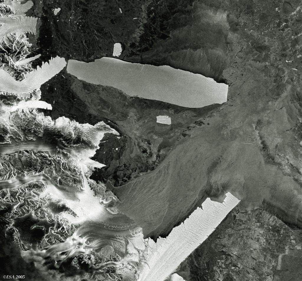
6 Ice 6
7 Oil slick Galicia, Spain 7

8 Nicobar Islands December 2004 tsunami flooding in red 8
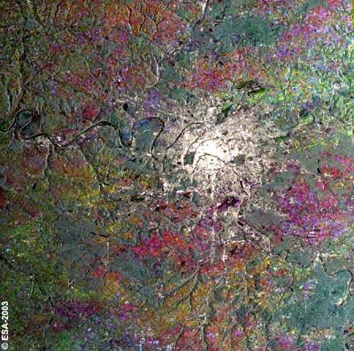
9 Paris 9
10 Definitions Radar - an acronym for Radio Detection And Ranging SLAR Sideways Looking Airborne Radar Measures range to scattering targets on the ground, can be used to form a low resolution image. SAR Synthetic Aperture Radar Same principle as SLAR, but uses image processing to create high resolution images IfSAR Interferometric SAR Generates X, Y, Z from two SAR images using principles of interferometry (phase difference) 10
11 References Henderson and Lewis, Principles and Applications of Imaging Radar, John Wiley and Sons Allan T D (ed) Satellite microwave remote sensing, Ellis Horwood, 1983 F. Ulaby, R. Moore and A. Fung, Microwave Remote Sensing: Active and Passive (3 vols), 1981, 1982, 1986 S. Kingsley and S. Quegan, Understanding Radar Systems, SciTech Publishing. C. Oliver and S. Quegan, Understanding Synthetic Aperture Radar Images, Artech House, Woodhouse I H (2000) Tutorial review. Stop, look and listen: auditory perception analogies for radar remote sensing, International Journal of Remote Sensing 21 (15), Jensen, J. R. (2000) Remote sensing of the Environment, Chapter 9. 11
12 Web sites Canada chapter3/01_e.php ESA spaceborne/radar_courses/ 12
13 What is RADAR? Radio Detection and Ranging Radar is a ranging instrument (range) distances inferred from time elapsed between transmission of a signal and reception of the returned signal imaging radars (side-looking) used to acquire images (~10m - 1km) altimeters (nadir-looking) to derive surface height variations scatterometers to derive reflectivity as a function of incident angle, illumination direction, polarisation, etc 13
14 What is RADAR? A Radar system has three primary functions: - It transmits microwave (radio) signals towards a scene - It receives the portion of the transmitted energy backscattered from the scene - It observes the strength (detection) and the time delay (ranging) of the return signals. Radar provides its own energy source and, therefore, can operate both day or night. This type of system is known as an active remote sensing system. 14

15 Principle of RADAR 15
16 Principle of ranging and imaging 16
17 Radar Pulse 17
18 18

19 ERS 1 and 2 geometry 19
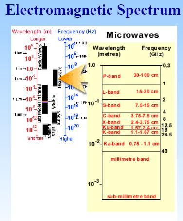
20 Radar wavelength Most remote sensing radars operate at wavelengths between 0.5 cm and 75 cm: X-band: from 2.4 to 3.75 cm (12.5 to 8 GHz). C-band: from 3.75 to 7.5 cm (8 to 4 GHz). S-band: from 7.5 to 15 cm (4 to 2 GHz). L-band: from 15 to 30 cm (2 to 1 GHz). P-band: from 30 to 100 cm (1 to 0.3 GHz). The capability to penetrate through precipitation or into a surface layer is increased with longer wavelengths. Radars operating at wavelengths > 2 cm are not significantly affected by cloud cover. Rain does become a factor at wavelengths < 4 cm. 20
21 21

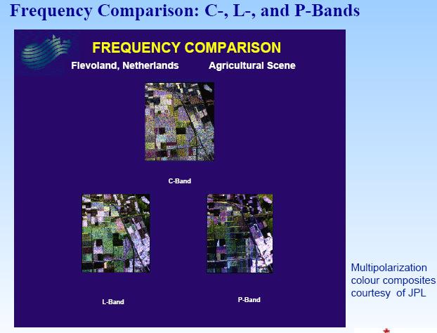
22 Comparison of C band and L band SAR C-band L-band 22
23 23
24 Choice of wave length Radar wavelength should be matched to the size of the surface features that we wish to discriminate e.g. Ice discrimination, small features, use X-band e.g. Geology mapping, large features, use L-band e.g. Foliage penetration, better at low frequencies, use P-band In general, C-band is a good compromise New airborne systems combine X and P band to give optimum measurement of vegetation 24
25 Synthetic Aperture Radar (SAR) Imaging side-looking accumulates data along path ground surface illuminated parallel and to one side of the flight direction. Data, processing is needed to produce radar images. The across-track dimension is the range. Near range edge is closest to nadir; far range edge is farthest from the radar. The along-track dimension is referred to as azimuth. Resolution is defined for both the range and azimuth directions. Digital signal processing is used to focus the image and obtain a higher resolution than achieved by conventional radar 25
26 26
27 Principle of Synthetic Aperture Radar SAR Doppler frequency due to sensor movement Use Doppler frequency shift (relative to reference pulse) due to sensor movement to recombine multiple pulses into a single coherent image from an apparently much larger (synthesised) aperture 27
28 Azimuth resolution: synthetic aperture v L a ψ R Target time spent in beam = arc length / v = Rψ / v = Rλ / vl 28 a
29 Resolution τ 29
30 Range and azimuth resolution (RAR) Range resolution (across track) Azimuth resolution (along track) R r = Tc 2cos! R a = S λ L T = duration of RADAR pulse T = o f the radar c = speed of light c = speed of light γ= depression angle ã = depression angle L = antenna length S = slant range = height/sinγ λ = wavelength cos : inverse relationship with angle 30
31 Resolution of SAR 31
32 Important point Resolution cell (i.e. the cell defined by the resolutions in the range and azimuth directions) does NOT mean the same thing as pixel. Pixel sizes need not be the same thing. This is important since (i) the independent elements in the scene are resolutions cells, (ii) neighbouring pixels may exhibit some correlation. 32
33 Some Spaceborne Systems Launch Agency properties resolution swath ERS-1 ERS (-1997) 1995 ESA C-VV 25 m 100 km Radarsat 1995 CSA C-HH m km JERS NASDA L-HH 18 m 76 km SIR-C/X-SAR 1994 (2x10 days) NASA DARA / ASI L,C, X polarimetric 30 m km 33
34 ERS 1 and 2 Specifications Geometric specifications Spatial resolution: along track <=30 m across-track <=26.3 m Swath width: km (telemetered) 80.4 km (full performance) Swath standoff: 250 km to the right of the satellite track Localisation accuracy: along track <=1 km; across-track <=0.9 km Incidence angle: near swath 20.1deg. mid swath 23deg. far swath 25.9deg Incidence angle tolerance: <=0.5 deg. Radiometric specifications: Frequency: 5.3 GHz (C-band) Wave length: 5.6 cm 34
35 Speckle Speckle appears as noisy fluctuations in brightness 35
36 Speckle Fading / speckle - noise-like processes due to coherent imaging system. Local constructive and destructive interference Average multiple independent samples, can effectively reduce the effects of speckle e.g. by Multiple-look filtering, separates the maximum synthetic aperture into smaller sub-apertures generating independent looks at target areas based on the angular position of the targets. Therefore, looks are different Doppler frequency bands. Averaging (incoherently) adjacent pixels. Reducing these effects enhances radiometric resolution at the expense of spatial resolution. 36

37 Speckle 37
38 Speckle Radar images are formed coherently and therefore inevitably have a noise-like appearance Implies that a single pixel is not representative of the backscattering Averaging needs to be done 38
39 Multi-looking Speckle can be suppressed by averaging several intensity images This is often done in SAR processing Split the synthetic aperture into N separate parts Suppressing the speckle means decreasing the width of the intensity distribution We also get a decrease in spatial resolution by the same factor (N) Note this is in the azimuth direction (because it relies on the motion of the sensor which is in this direction) 39

40 Speckle 40
41 Principle of ranging and imaging 41

42 Geometric effects 42
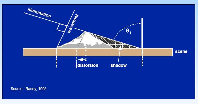
43 Shadow 43
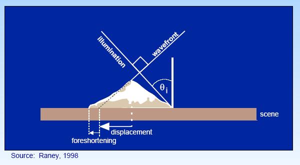
44 Foreshortening 44

45 Layover 45

46 Layover 46
47 Los Angeles 47
48 Radiometric aspects the RADAR equation P r = (Power per unit area at target ) Eff. scatt. area of target Spread loss of reflected signal Eff. Antennae area Brightness is a combination of several variables. We can group these characteristics into three areas which fundamentally control radar energy/target interactions. They are: Surface roughness of the target Radar viewing and surface geometry relationship Moisture content and electrical properties of the target spaceborne/radar_courses/radar_course_iii/ radar_equation.htm 48
49 Returned energy Angle of the surface to the incident radar beam Strong from facing areas, weak from areas facing away Physical properties of the sensed surface Surface roughness Dielectric constant Water content of the surface Smooth Rough 49
50 Roughness Smooth, intermediate or rough? Jensen (2002; p314) surface height variation h Smooth: h < λ/25sin β Rough: h > λ/4.4sin β Intermediate β is depression angle, so depends on λ AND imaging geometry 50

51 Oil slick Galicia, Spain 51

52 Los Angeles 52

53 Response to soil moisture Source: Graham


54 Crop moisture SAR image In situ irrigation Source: Graham
55 Types of scattering of radar from different surfaces 55
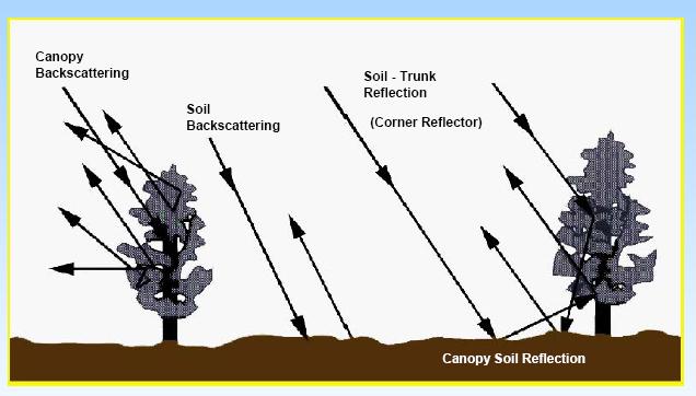
56 Scattering 56
57 The Radar Equation The fundamental relation between the characteristics of the radar, the target, and the received signal is called the radar equation. The geometry of scattering from an isolated radar target (scatterer) is shown. When a power P t is transmitted by an antenna with gain G t, the power per unit solid angle in the direction of the scatterer is P t G t, where the value of G t in that direction is used. READ: Radar_Courses/Radar_Course_III/radar_equation.htm and Jensen Chapter 9 57
58 The Radar Equation We may rewrite the radar equation as two alternative forms, one in terms of the antenna gain and the other in terms of the antenna area R = range P = power G = gain of antenna A = area of the antenna Because Where: The Radar scattering cross section The cross-section σ is a function of the directions of the incident wave and the wave toward the receiver, as well as that of the scatterer shape and dielectric properties. f a is absorption A rs is effective area of incident beam received by scatterer G ts is gain of the scatterer in the direction of the receiver READ: radar_equation.htm And Jensen Chapter 9 58
59 Measured quantities Radar cross section [dbm 2 ] lim E! = r # $ 4" r 2 s i E 2 2 Bistatic scattering coefficient [db] "! 0 4 = lim r r $ % Acos# i 2 s 2 E i E 2 Backscattering coefficient [db]! 0 4" r = r # $ A 2 s 2 E lim i E 2 59
60 The Radar Equation: Point targets Power received 1 1 P = P G " r t t 2 2 4! R 4! R A r G t is the transmitter gain, A r is the effective area of receiving antenna and σ the effective area of the target. Assuming same transmitter and receiver, A/G=λ 2 /4π 2 2 " G! P = P $ r t 3 4 ( 4# ) R 60


61 Calibration of SAR Emphasis is on radiometric calibration to determine the radar cross section Calibration is done in the field, using test sites with transponders. 61
Synthetic aperture RADAR (SAR) principles/instruments October 31, 2018
 principles/instruments October 31, 2018") GEOL 1460/2461 Ramsey Introduction to Remote Sensing Fall, 2018 Synthetic aperture RADAR (SAR) principles/instruments October 31, 2018 I. Reminder: Upcoming Dates lab #2 reports due by the start of next
GEOL 1460/2461 Ramsey Introduction to Remote Sensing Fall, 2018 Synthetic aperture RADAR (SAR) principles/instruments October 31, 2018 I. Reminder: Upcoming Dates lab #2 reports due by the start of next
Remote Sensing. Ch. 3 Microwaves (Part 1 of 2)
") Remote Sensing Ch. 3 Microwaves (Part 1 of 2) 3.1 Introduction 3.2 Radar Basics 3.3 Viewing Geometry and Spatial Resolution 3.4 Radar Image Distortions 3.1 Introduction Microwave (1cm to 1m in wavelength)
Remote Sensing Ch. 3 Microwaves (Part 1 of 2) 3.1 Introduction 3.2 Radar Basics 3.3 Viewing Geometry and Spatial Resolution 3.4 Radar Image Distortions 3.1 Introduction Microwave (1cm to 1m in wavelength)
ACTIVE SENSORS RADAR
 ACTIVE SENSORS RADAR RADAR LiDAR: Light Detection And Ranging RADAR: RAdio Detection And Ranging SONAR: SOund Navigation And Ranging Used to image the ocean floor (produce bathymetic maps) and detect objects
Acknowledgment. Process of Atmospheric Radiation. Atmospheric Transmittance. Microwaves used by Radar GMAT Principles of Remote Sensing
 GMAT 9600 Principles of Remote Sensing Week 4 Radar Background & Surface Interactions Acknowledgment Mike Chang Natural Resources Canada Process of Atmospheric Radiation Dr. Linlin Ge and Prof Bruce Forster
ESA Radar Remote Sensing Course ESA Radar Remote Sensing Course Radar, SAR, InSAR; a first introduction
 Radar, SAR, InSAR; a first introduction Ramon Hanssen Delft University of Technology The Netherlands r.f.hanssen@tudelft.nl Charles University in Prague Contents Radar background and fundamentals Imaging
Microwave Remote Sensing (1)
") Microwave Remote Sensing (1) Microwave sensing encompasses both active and passive forms of remote sensing. The microwave portion of the spectrum covers the range from approximately 1cm to 1m in wavelength.
Microwave Remote Sensing (1) Microwave sensing encompasses both active and passive forms of remote sensing. The microwave portion of the spectrum covers the range from approximately 1cm to 1m in wavelength.
Radar Imaging Wavelengths
 A Basic Introduction to Radar Remote Sensing ~~~~~~~~~~ Rev. Ronald J. Wasowski, C.S.C. Associate Professor of Environmental Science University of Portland Portland, Oregon 3 November 2015 Radar Imaging
Microwave Remote Sensing
 Provide copy on a CD of the UCAR multi-media tutorial to all in class. Assign Ch-7 and Ch-9 (for two weeks) as reading material for this class. HW#4 (Due in two weeks) Problems 1,2,3 and 4 (Chapter 7)
RADAR REMOTE SENSING
 RADAR REMOTE SENSING Jan G.P.W. Clevers & Steven M. de Jong Chapter 8 of L&K 1 Wave theory for the EMS: Section 1.2 of L&K E = electrical field M = magnetic field c = speed of light : propagation direction
Introduction Active microwave Radar
 RADAR Imaging Introduction 2 Introduction Active microwave Radar Passive remote sensing systems record electromagnetic energy that was reflected or emitted from the surface of the Earth. There are also
SAR Remote Sensing (Microwave Remote Sensing)
") iirs SAR Remote Sensing (Microwave Remote Sensing) Synthetic Aperture Radar Shashi Kumar shashi@iirs.gov.in Electromagnetic Radiation Electromagnetic radiation consists of an electrical field(e) which
iirs SAR Remote Sensing (Microwave Remote Sensing) Synthetic Aperture Radar Shashi Kumar shashi@iirs.gov.in Electromagnetic Radiation Electromagnetic radiation consists of an electrical field(e) which
Imaging radar Imaging radars provide map-like coverage to one or both sides of the aircraft.
 CEE 6100 / CSS 6600 Remote Sensing Fundamentals 1 Imaging radar Imaging radars provide map-like coverage to one or both sides of the aircraft. Acronyms: RAR real aperture radar ("brute force", "incoherent")
10 Radar Imaging Radar Imaging
 10 Radar Imaging Active sensors provide their own source of energy to illuminate the target. Active sensors are generally divided into two distinct categories: imaging and non-imaging. The most common
EE 529 Remote Sensing Techniques. Introduction
 EE 529 Remote Sensing Techniques Introduction Course Contents Radar Imaging Sensors Imaging Sensors Imaging Algorithms Imaging Algorithms Course Contents (Cont( Cont d) Simulated Raw Data y r Processing
RADAR (RAdio Detection And Ranging)
") RADAR (RAdio Detection And Ranging) CLASSIFICATION OF NONPHOTOGRAPHIC REMOTE SENSORS PASSIVE ACTIVE DIGITAL CAMERA THERMAL (e.g. TIMS) VIDEO CAMERA MULTI- SPECTRAL SCANNERS VISIBLE & NIR MICROWAVE Real
RADAR (RAdio Detection And Ranging) CLASSIFICATION OF NONPHOTOGRAPHIC REMOTE SENSORS PASSIVE ACTIVE DIGITAL CAMERA THERMAL (e.g. TIMS) VIDEO CAMERA MULTI- SPECTRAL SCANNERS VISIBLE & NIR MICROWAVE Real
Introduction to Radar
 National Aeronautics and Space Administration ARSET Applied Remote Sensing Training http://arset.gsfc.nasa.gov @NASAARSET Introduction to Radar Jul. 16, 2016 www.nasa.gov Objective The objective of this
ACTIVE MICROWAVE REMOTE SENSING OF LAND SURFACE HYDROLOGY
 Basics, methods & applications ACTIVE MICROWAVE REMOTE SENSING OF LAND SURFACE HYDROLOGY Annett.Bartsch@polarresearch.at Active microwave remote sensing of land surface hydrology Landsurface hydrology:
Active and Passive Microwave Remote Sensing
 Active and Passive Microwave Remote Sensing Passive remote sensing system record EMR that was reflected (e.g., blue, green, red, and near IR) or emitted (e.g., thermal IR) from the surface of the Earth.
Introduction to Imaging Radar INF-GEO 4310
 Introduction to Imaging Radar INF-GEO 4310 22.9.2011 Literature Contact: yoann.paichard@ffi.no Suggested readings: Fundamentals of Radar Signal Processing, M.A. Richards, McGraw-Hill, 2005 High Resolution
Specificities of Near Nadir Ka-band Interferometric SAR Imagery
 Specificities of Near Nadir Ka-band Interferometric SAR Imagery Roger Fjørtoft, Alain Mallet, Nadine Pourthie, Jean-Marc Gaudin, Christine Lion Centre National d Etudes Spatiales (CNES), France Fifamé
SAR Remote Sensing. Introduction into SAR. Data characteristics, challenges, and applications.
 SAR Remote Sensing Introduction into SAR. Data characteristics, challenges, and applications. PD Dr. habil. Christian Thiel, Friedrich-Schiller-University Jena DLR-HR Jena & Friedrich-Schiller-University
MODULE 9 LECTURE NOTES 2 ACTIVE MICROWAVE REMOTE SENSING
 MODULE 9 LECTURE NOTES 2 ACTIVE MICROWAVE REMOTE SENSING 1. Introduction Satellite sensors are capable of actively emitting microwaves towards the earth s surface. An active microwave system transmits
Synthetic Aperture Radar
 Synthetic Aperture Radar Picture 1: Radar silhouette of a ship, produced with the ISAR-Processor of the Ocean Master A Synthetic Aperture Radar (SAR), or SAR, is a coherent mostly airborne or spaceborne
Interpreting Digital RADAR Images
 R A D A R Introduction to Interpreting Digital Radar Images I N T E R P R E T Interpreting Digital RADAR Images with TNTmips page 1 Before Getting Started Airborne and satellite radar systems are versatile
Introduction to Microwave Remote Sensing
 Introduction to Microwave Remote Sensing lain H. Woodhouse The University of Edinburgh Scotland Taylor & Francis Taylor & Francis Group Boca Raton London New York A CRC title, part of the Taylor & Francis
Review. Guoqing Sun Department of Geography, University of Maryland ABrief
 Review Guoqing Sun Department of Geography, University of Maryland gsun@glue.umd.edu ABrief Introduction Scattering Mechanisms and Radar Image Characteristics Data Availability Example of Applications
Remote Sensing 1 Principles of visible and radar remote sensing & sensors
 Remote Sensing 1 Principles of visible and radar remote sensing & sensors Nick Barrand School of Geography, Earth & Environmental Sciences University of Birmingham, UK Field glaciologist collecting data
SATELLITE OCEANOGRAPHY
 SATELLITE OCEANOGRAPHY An Introduction for Oceanographers and Remote-sensing Scientists I. S. Robinson Lecturer in Physical Oceanography Department of Oceanography University of Southampton JOHN WILEY
Active and Passive Microwave Remote Sensing
 Active and Passive Microwave Remote Sensing Passive remote sensing system record EMR that was reflected (e.g., blue, green, red, and near IR) or emitted (e.g., thermal IR) from the surface of the Earth.
Design of an Airborne SLAR Antenna at X-Band
 Design of an Airborne SLAR Antenna at X-Band Markus Limbach German Aerospace Center (DLR) Microwaves and Radar Institute Oberpfaffenhofen WFMN 2007, Markus Limbach, Folie 1 Overview Applications of SLAR
Radar and Satellite Remote Sensing. Chris Allen, Associate Director Technology Center for Remote Sensing of Ice Sheets The University of Kansas
 Radar and Satellite Remote Sensing Chris Allen, Associate Director Technology Center for Remote Sensing of Ice Sheets The University of Kansas 2of 43 Outline Background ice sheet characterization Radar
Fundamentals of Remote Sensing: the Imaging RADAR System
 INSIS Fundamentals of Remote Sensing: the Imaging RADAR System Notions fondamentales de télédétection : le RADAR imageur Gabriel VASILE Chargé de Recherche CNRS gabriel.vasile@gipsa-lab.grenoble-inp.fr
Microwave remote sensing. Rudi Gens Alaska Satellite Facility Remote Sensing Support Center
 Microwave remote sensing Alaska Satellite Facility Remote Sensing Support Center 1 Remote Sensing Fundamental The entire range of EM radiation constitute the EM Spectrum SAR sensors sense electromagnetic
Co-ReSyF RA lecture: Vessel detection and oil spill detection
 This project has received funding from the European Union s Horizon 2020 Research and Innovation Programme under grant agreement no 687289 Co-ReSyF RA lecture: Vessel detection and oil spill detection
GMES Sentinel-1 Transponder Development
 GMES Sentinel-1 Transponder Development Paul Snoeij Evert Attema Björn Rommen Nicolas Floury Malcolm Davidson ESA/ESTEC, European Space Agency, Noordwijk, The Netherlands Outline 1. GMES Sentinel-1 overview
Radar Polarimetry- Potential for Geosciences
 Radar Polarimetry- Potential for Geosciences Franziska Kersten Department of geology, TU Freiberg Abstract. The ability of Radar Polarimetry to obtain information about physical properties of the surface
Introduction to RADAR Remote Sensing for Vegetation Mapping and Monitoring. Wayne Walker, Ph.D.
 Introduction to RADAR Remote Sensing for Vegetation Mapping and Monitoring Wayne Walker, Ph.D. Outline What is RADAR (and what does it measure)? RADAR as an active sensor Applications of RADAR to vegetation
Introduction to SAR remote sensing Ramon Hanssen
 1 Introduction to SAR remote sensing Ramon Hanssen 10-9-2018 Delft University of Technology Challenge the future 1 Obectives of the module Provide the basic essentials of SAR remote sensing, and understand
SCIRoCCo Scatterometry Glossary
 Scatterometry Prepared by: The Team: Change register Version/Rev. Date Reason for Change Changes 1.0 08/05/2014 First Release. Preliminary version 1.1 20/02/2015 4 th bi-monthly Report Review Contributions
ATS 351 Lecture 9 Radar
 ATS 351 Lecture 9 Radar Radio Waves Electromagnetic Waves Consist of an electric field and a magnetic field Polarization: describes the orientation of the electric field. 1 Remote Sensing Passive vs Active
Remote sensing of the oceans Active sensing
 Remote sensing of the oceans Active sensing Gravity Sea level Ocean tides Low frequency motion Scatterometry SAR http://daac.gsfc.nasa.gov/campaign_docs/ocdst/what_is_ocean_color.html Shape of the earth
remote sensing? What are the remote sensing principles behind these Definition
 Introduction to remote sensing: Content (1/2) Definition: photogrammetry and remote sensing (PRS) Radiation sources: solar radiation (passive optical RS) earth emission (passive microwave or thermal infrared
LE/ESSE Payload Design
 LE/ESSE4360 - Payload Design 3.4 Spacecraft Sensors - Radar Sensors Earth, Moon, Mars, and Beyond Dr. Jinjun Shan, Professor of Space Engineering Department of Earth and Space Science and Engineering Room
SAR Multi-Temporal Applications
 SAR Multi-Temporal Applications 83230359-DOC-TAS-EN-001 Contents 2 Advantages of SAR Remote Sensing Technology All weather any time Frequencies and polarisations Interferometry and 3D mapping Change Detection
Theoretical Simulations of GNSS Reflections from Bare and Vegetated Soils
 Theoretical Simulations of GNSS Reflections from Bare and Vegetated Soils R. Giusto 1, L. Guerriero, S. Paloscia 3, N. Pierdicca 1, A. Egido 4, N. Floury 5 1 DIET - Sapienza Univ. of Rome, Rome DISP -
Calibration Assessment of RADARSAT-2 Polarimetry Using High Precision Transponders
 Calibration Assessment of RADARSAT-2 Polarimetry Using High Precision Transponders R Touzi, S Côté, RK Hawkins CCRS/CSA Acknowledgments S Nedelcu (CCRS) S Muir (CSA) 1 Outline-Polarimetric RADARSAT-2 Independent
Dynamics and Control Issues for Future Multistatic Spaceborne Radars
 Dynamics and Control Issues for Future Multistatic Spaceborne Radars Dr Stephen Hobbs Space Research Centre, School of Engineering, Cranfield University, UK Abstract Concepts for future spaceborne radar
Outline. Introduction. Introduction: Film Emulsions. Sensor Systems. Types of Remote Sensing. A/Prof Linlin Ge. Photographic systems (cf(
 GMAT x600 Remote Sensing / Earth Observation Types of Sensor Systems (1) Outline Image Sensor Systems (i) Line Scanning Sensor Systems (passive) (ii) Array Sensor Systems (passive) (iii) Antenna Radar
MULTI-CHANNEL SAR EXPERIMENTS FROM THE SPACE AND FROM GROUND: POTENTIAL EVOLUTION OF PRESENT GENERATION SPACEBORNE SAR
 3 nd International Workshop on Science and Applications of SAR Polarimetry and Polarimetric Interferometry POLinSAR 2007 January 25, 2007 ESA/ESRIN Frascati, Italy MULTI-CHANNEL SAR EXPERIMENTS FROM THE
THE NASA/JPL AIRBORNE SYNTHETIC APERTURE RADAR SYSTEM. Yunling Lou, Yunjin Kim, and Jakob van Zyl
 THE NASA/JPL AIRBORNE SYNTHETIC APERTURE RADAR SYSTEM Yunling Lou, Yunjin Kim, and Jakob van Zyl Jet Propulsion Laboratory California Institute of Technology 4800 Oak Grove Drive, MS 300-243 Pasadena,
Introduction To Microwave Remote Sensing. Contents. Introduction To Microwave Remote Sensing
 Introduction To Microwave Remote Sensing David P. Lusch, Ph.D. Senior Research Specialist Center For Remote Sensing and Geographic Information Science Michigan State University November, 1999 Introduction
Microwave sensors (present and future)
") Proc. Indian Acad. Sci. (Engg. sea.), Vol. 6, Pt. 2, June 1983, pp. 109-119. 9 Printed in India. Microwave sensors (present and future) 1. Introduction O P N CALLA Communications Area, Space Applications
Proc. Indian Acad. Sci. (Engg. sea.), Vol. 6, Pt. 2, June 1983, pp. 109-119. 9 Printed in India. Microwave sensors (present and future) 1. Introduction O P N CALLA Communications Area, Space Applications
China. France Oceanography S A T. Overview of the near-real time wave products of the CFOSAT mission. e l l i t e
 China Overview of the near-real time wave products of the CFOSAT mission C. Tison (1), D. Hauser (2), S. Guibert (1), T. Amiot (1), L. Aouf (3), J.M. Lefèvre (3), B. Chapron (5), N. Corcoral (1), P. Castillan
The Global Imager (GLI)
") The Global Imager (GLI) Launch : Dec.14, 2002 Initial check out : to Apr.14, 2003 (~L+4) First image: Jan.25, 2003 Second image: Feb.6 and 7, 2003 Calibration and validation : to Dec.14, 2003(~L+4) for
The Global Imager (GLI) Launch : Dec.14, 2002 Initial check out : to Apr.14, 2003 (~L+4) First image: Jan.25, 2003 Second image: Feb.6 and 7, 2003 Calibration and validation : to Dec.14, 2003(~L+4) for
Observing Dry-Fallen Intertidal Flats in the German Bight Using ALOS PALSAR Together With Other Remote Sensing Sensors
 Observing Dry-Fallen Intertidal Flats in the German Bight Using ALOS PALSAR Together With Other Remote Sensing Sensors Martin Gade, Institut für Meereskunde & Kerstin Stelzer Brockmann Consult Outline
Biomass, a polarimetric interferometric P-band SAR mission
 Biomass, a polarimetric interferometric P-band SAR mission M. Arcioni, P. Bensi, M. Fehringer, F. Fois, F. Heliere, N. Miranda, K. Scipal Fringe 2015, ESRIN 27/03/2015 The Biomass Mission 1. Biomass was
All rights reserved. ENVI, IDL and Jagwire are trademarks of Exelis, Inc. All other marks are the property of their respective owners.
 SAR Analysis Made Easy with SARscape 5.1 All rights reserved. ENVI, IDL and Jagwire are trademarks of Exelis, Inc. All other marks are the property of their respective owners. 2014, Exelis Visual Information
Earth Observation from a Moon based SAR: Potentials and Limitations
 Earth Observation from a Moon based SAR: Potentials and Limitations F. Bovenga 1, M. Calamia 2,3, G. Fornaro 5, G. Franceschetti 4, L. Guerriero 1, F. Lombardini 5, A. Mori 2 1 Politecnico di Bari - Dipartimento
746A27 Remote Sensing and GIS
 746A27 Remote Sensing and GIS Lecture 1 Concepts of remote sensing and Basic principle of Photogrammetry Chandan Roy Guest Lecturer Department of Computer and Information Science Linköping University What
Change detection in cultural landscapes
 9-11 November 2015 ESA-ESRIN, Frascati (Rome), Italy 3 rd ESA-EARSeL Course on Remote Sensing for Archaeology Day 3 Change detection in cultural landscapes DeodatoTapete (1,2) & Francesca Cigna (1,2) (1)
MODULE 9 LECTURE NOTES 1 PASSIVE MICROWAVE REMOTE SENSING
 MODULE 9 LECTURE NOTES 1 PASSIVE MICROWAVE REMOTE SENSING 1. Introduction The microwave portion of the electromagnetic spectrum involves wavelengths within a range of 1 mm to 1 m. Microwaves possess all
Synthetic Aperture Radar (SAR) images features clustering using Fuzzy c- means (FCM) clustering algorithm
 images features clustering using Fuzzy c- means (FCM) clustering algorithm") Article Synthetic Aperture Radar (SAR) images features clustering using Fuzzy c- means (FCM) clustering algorithm Rashid Hussain Faculty of Engineering Science and Technology, Hamdard University, Karachi
Article Synthetic Aperture Radar (SAR) images features clustering using Fuzzy c- means (FCM) clustering algorithm Rashid Hussain Faculty of Engineering Science and Technology, Hamdard University, Karachi
11. RADAR REMOTE SENSING
 Philpot & Philipson: Remote Sensing Fundamentals Radar 1 11. RADAR REMOTE SENSING 11.1 A bit of history RADAR was initially an acronym standing for RAdio Detection And Ranging 1. Radio waves were first
Microwave Sensors Subgroup (MSSG) Report
 Report") Microwave Sensors Subgroup (MSSG) Report Feb 17-20, 2014, ESA ESRIN, Frascati, Italy DONG, Xiaolong, MSSG Chair National Space Science Center Chinese Academy of Sciences (MiRS,NSSC,CAS) Email: dongxiaolong@mirslab.cn
Microwave Sensors Subgroup (MSSG) Report Feb 17-20, 2014, ESA ESRIN, Frascati, Italy DONG, Xiaolong, MSSG Chair National Space Science Center Chinese Academy of Sciences (MiRS,NSSC,CAS) Email: dongxiaolong@mirslab.cn
Sources of Geographic Information
 Sources of Geographic Information Data properties: Spatial data, i.e. data that are associated with geographic locations Data format: digital (analog data for traditional paper maps) Data Inputs: sampled
Sub-Mesoscale Imaging of the Ionosphere with SMAP
 Sub-Mesoscale Imaging of the Ionosphere with SMAP Tony Freeman Xiaoqing Pi Xiaoyan Zhou CEOS Workshop, ASF, Fairbanks, Alaska, December 2009 1 Soil Moisture Active-Passive (SMAP) Overview Baseline Mission
Synthetic Aperture Radar for Rapid Flood Extent Mapping
 National Aeronautics and Space Administration ARSET Applied Remote Sensing Training http://arset.gsfc.nasa.gov @NASAARSET Synthetic Aperture Radar for Rapid Flood Extent Mapping Sang-Ho Yun ARIA Team Jet
Microwave Sensors Subgroup (MSSG) Report
 Report") Microwave Sensors Subgroup (MSSG) Report CEOS WGCV-35 May 13-17, 2013, Shanghai, China DONG, Xiaolong, MSSG Chair CAS Key Laboratory of Microwave Remote Sensing National Space Science Center Chinese Academy
Microwave Sensors Subgroup (MSSG) Report CEOS WGCV-35 May 13-17, 2013, Shanghai, China DONG, Xiaolong, MSSG Chair CAS Key Laboratory of Microwave Remote Sensing National Space Science Center Chinese Academy
ECE Lecture 32
 ECE 5010 - Lecture 32 1 Microwave Radiometry 2 Properties of a Radiometer 3 Radiometric Calibration and Uncertainty 4 Types of Radiometer Measurements Levis, Johnson, Teixeira (ESL/OSU) Radiowave Propagation
RECOMMENDATION ITU-R S *
 Rec. ITU-R S.1339-1 1 RECOMMENDATION ITU-R S.1339-1* Rec. ITU-R S.1339-1 SHARING BETWEEN SPACEBORNE PASSIVE SENSORS OF THE EARTH EXPLORATION-SATELLITE SERVICE AND INTER-SATELLITE LINKS OF GEOSTATIONARY-SATELLITE
Soil moisture retrieval using ALOS PALSAR
 Soil moisture retrieval using ALOS PALSAR T. J. Jackson, R. Bindlish and M. Cosh USDA ARS Hydrology and Remote Sensing Lab, Beltsville, MD J. Shi University of California Santa Barbara, CA November 6,
The Potential of Synthetic Aperture Sonar in seafloor imaging
 The Potential of Synthetic Aperture Sonar in seafloor imaging CM 2000/T:12 Ron McHugh Heriot-Watt University, Department of Computing and Electrical Engineering, Edinburgh, EH14 4AS, Scotland, U.K. Tel:
Soil Moisture Observation Utilizing Reflected GNSS Signals
 Soil Moisture Observation Utilizing Reflected GNSS Signals GNSS-R Tech in Soil Moisture New Data Processing Method Prof. Dongkai YANG Joint African/Asia-Pacific UN-Regional Centers and International Training
NEXTMAP. P-Band. Airborne Radar Imaging Technology. Key Benefits & Features INTERMAP.COM. Answers Now
 INTERMAP.COM Answers Now NEXTMAP P-Band Airborne Radar Imaging Technology Intermap is proud to announce the latest advancement of their Synthetic Aperture Radar (SAR) imaging technology. Leveraging over
The Sentinel-1 Constellation
 The Sentinel-1 Constellation Evert Attema, Sentinel-1 Mission & System Manager AGRISAR and EAGLE Campaigns Final Workshop 15-16 October 2007 ESA/ESTECNoordwijk, The Netherlands Sentinel-1 Programme Sentinel-1
Bistatic/Monostatic Synthetic Aperture Radar for Ice Sheet Measurements
 Bistatic/Monostatic Snthetic Aperture Radar for Ice Sheet Measurements John Paden MS Thesis Defense April 18, 003 Committee Chairperson: Dr. Chris Allen Committee Members: Dr. Prasad Gogineni Dr. Glenn
Multipath Analysis of the QuikSCAT Calibration Ground Station
 Brigham Young University Department of Electrical and Computer Engineering 459 Clyde Building Provo, Utah 8462 Multipath Analysis of the QuikSCAT Calibration Ground Station Arden Anderson 16 April 21 MERS
Chapter 6 Spaceborne SAR Antennas for Earth Science
 Chapter 6 Spaceborne SAR Antennas for Earth Science Yunjin Kim and Rolando L. Jordan 6.1 Introduction Before the development of the first synthetic aperture radar (SAR) antenna flown in space, Jet Propulsion
Configuration, Capabilities, Limitations, and Examples
 FUGRO EARTHDATA, Inc. Introduction to the New GeoSAR Interferometric Radar Sensor Bill Sharp GeoSAR Regional Director - Americas Becky Morton Regional Manager Configuration, Capabilities, Limitations,
Radiometric and Geometric Correction Methods for Active Radar and SAR Imageries
 Radiometric and Geometric Correction Methods for Active Radar and SAR Imageries M. Mansourpour 1, M.A. Rajabi 1, Z. Rezaee 2 1 Dept. of Geomatics Eng., University of Tehran, Tehran, Iran mansourpour@gmail.com,
Generation of Fine Resolution DEM at Test Areas in Alaska Using ERS SAR Tandem Pairs and Precise Orbital Data *
 Generation of Fine Resolution DEM at Test Areas in Alaska Using ERS SAR Tandem Pairs and Precise Orbital Data * O. Lawlor, T. Logan, R. Guritz, R. Fatland, S. Li, Z. Wang, and C. Olmsted Alaska SAR Facility
SPATIAL MAPPING OF SOIL MOISTURE USING RADARSAT-1 DATA INTRODUCTION
 SPATIAL MAPPING OF SOIL MOISTURE USING RADARSAT-1 DATA Tarendra Lakhankar, PhD Student Hosni Ghedira, Asst. Professor Reza Khanbilvardi, Professor NOAA-CREST, City University of New York New York 10031
Contribution of Sentinel-1 data for the monitoring of seasonal variations of the vegetation
 Contribution of Sentinel-1 data for the monitoring of seasonal variations of the vegetation P.-L. Frison, S. Kmiha, B. Fruneau, K. Soudani, E. Dufrêne, T. Koleck, L. Villard, M. Lepage, J.-F. Dejoux, J.-P.
An Introduction to Remote Sensing & GIS. Introduction
 An Introduction to Remote Sensing & GIS Introduction Remote sensing is the measurement of object properties on Earth s surface using data acquired from aircraft and satellites. It attempts to measure something
John P. Stevens HS: Remote Sensing Test
 Name(s): Date: Team name: John P. Stevens HS: Remote Sensing Test 1 Scoring: Part I - /18 Part II - /40 Part III - /16 Part IV - /14 Part V - /93 Total: /181 2 I. History (3 pts. each) 1. What is the name
Concept Design of Space-Borne Radars for Tsunami Detection
 Concept Design of Space-Borne Radars for Tsunami Detection DLR German Aerospace Agency +Microwaves and Radar Institute *Remote Sensing Institute +Michele Galletti +Gerhard Krieger +Nicolas Marquart +Thomas
Synthetic Aperture Radar. Hugh Griffiths THALES/Royal Academy of Engineering Chair of RF Sensors University College London
 Synthetic Aperture Radar Hugh Griffiths THALES/Royal Academy of Engineering Chair of RF Sensors University College London CEOI Training Workshop Designing and Delivering and Instrument Concept 15 March
Scientific Applications of Fully-Focused SAR Altimetry
 Scientific Applications of Fully-Focused SAR Altimetry Alejandro Egido (1,2), Walter Smith (2) (1) UMD/CICS-MD, United States (2) NOAA, United States CICS Science Conference Nov 29, 30 & Dec 1, 2016 College
CURRENT APPLICATIONS OF IMAGING RADAR
 CURRENT APPLICATIONS OF IMAGING RADAR M.R. Inggs and R.T. Lord Dept. Electrical Engineering, University of Cape Town, Rondebosch, 7701, South Africa mikings@ebe.uct.ac.za Commission VII, WG VII/2 KEY WORDS:
SAR AUTOFOCUS AND PHASE CORRECTION TECHNIQUES
 SAR AUTOFOCUS AND PHASE CORRECTION TECHNIQUES Chris Oliver, CBE, NASoftware Ltd 28th January 2007 Introduction Both satellite and airborne SAR data is subject to a number of perturbations which stem from
REMOTE SENSING FOR FLOOD HAZARD STUDIES.
 REMOTE SENSING FOR FLOOD HAZARD STUDIES. OPTICAL SENSORS. 1 DRS. NANETTE C. KINGMA 1 Optical Remote Sensing for flood hazard studies. 2 2 Floods & use of remote sensing. Floods often leaves its imprint
Figure 1: C band and L band (SIR-C/X-SAR images of Flevoland in Holland). color scheme: HH: red, HV:green, VV: blue
. color scheme: HH: red, HV:green, VV: blue") L-band PS analysis: JERS-1 results and TerraSAR L predictions Kenji Daito (1), Alessandro Ferretti (), Shigeki Kuzuoka (3),Fabrizio Novali (), Pietro Panzeri (), Fabio Rocca (4) (1) Daido Institute of
L-band PS analysis: JERS-1 results and TerraSAR L predictions Kenji Daito (1), Alessandro Ferretti (), Shigeki Kuzuoka (3),Fabrizio Novali (), Pietro Panzeri (), Fabio Rocca (4) (1) Daido Institute of
Evaluation of Multi-Frequency and Multi-Polarization Airborne SAR data for Marsh Land and River Dyke Analysis
 Photogrammetric Week '03 Dieter Fritsch (Ed.) Wichmann Verlag, Heidelberg, 2003 Müllenhoff 197 Evaluation of Multi-Frequency and Multi-Polarization Airborne SAR data for Marsh Land and River Dyke Analysis
Playa del Rey, California InSAR Ground Deformation Monitoring Interim Report H
 Playa del Rey, California InSAR Ground Deformation Monitoring Interim Report H Ref.: RV-14524 Doc.: CM-168-01 January 31, 2013 SUBMITTED TO: Southern California Gas Company 555 W. Fifth Street (Mail Location
Ultrasound Beamforming and Image Formation. Jeremy J. Dahl
 Ultrasound Beamforming and Image Formation Jeremy J. Dahl Overview Ultrasound Concepts Beamforming Image Formation Absorption and TGC Advanced Beamforming Techniques Synthetic Receive Aperture Parallel
Measurements of the Propagation Parameters of Tree Canopies at. MMW Frequencies
 Measurements of the Propagation Parameters of Tree Canopies at MMW Frequencies A. Y. Nashashibi, F.T. Ulaby, P. Frantzis, and Roger D. De Roo The Radiation Laboratory Department of Electrical Engineering
Principles of Remote Sensing. Shuttle Radar Topography Mission S R T M. Michiel Damen. Dept. Earth Systems Analysis
 Principles of Remote Sensing Shuttle Radar Topography Mission S R T M Michiel Damen Dept. Earth Systems Analysis Contents Present problems with DEMs Advantage of SRTM Cell size Mission and system Radar
Synthetic Aperture Radar Interferometry (InSAR) Technique (Lecture I- Tuesday 11 May 2010)
 Technique (Lecture I- Tuesday 11 May 2010)") Synthetic Aperture Radar Interferometry () Technique (Lecture I- Tuesday 11 May 2010) ISNET/CRTEAN Training Course on Synthetic Aperture Radar (SAR) Imagery: Processing, Interpretation and Applications
Synthetic Aperture Radar Interferometry () Technique (Lecture I- Tuesday 11 May 2010) ISNET/CRTEAN Training Course on Synthetic Aperture Radar (SAR) Imagery: Processing, Interpretation and Applications
Detection of a Point Target Movement with SAR Interferometry
 Journal of the Korean Society of Remote Sensing, Vol.16, No.4, 2000, pp.355~365 Detection of a Point Target Movement with SAR Interferometry Jung-Hee Jun* and Min-Ho Ka** Agency for Defence Development*,
Channel Modeling and Characteristics
 Channel Modeling and Characteristics Dr. Farid Farahmand Updated:10/15/13, 10/20/14 Line-of-Sight Transmission (LOS) Impairments The received signal is different from the transmitted signal due to transmission