Radar and Satellite Remote Sensing. Chris Allen, Associate Director Technology Center for Remote Sensing of Ice Sheets The University of Kansas
|
|
|
- Zoe Jessica Ramsey
- 6 years ago
- Views:
Transcription


1 Radar and Satellite Remote Sensing Chris Allen, Associate Director Technology Center for Remote Sensing of Ice Sheets The University of Kansas
 Satellite sensing Spaceborne radars Satellite radar data products Future")
2 2of 43 Outline Background ice sheet characterization Radar overview Radar basics Radar depth-sounding of ice sheets Example of capabilities of modern radars Synthetic-aperture radar (SAR) Satellite sensing Spaceborne radars Satellite radar data products Future directions


3 Background 3of 43 Sea-level rise resulting from the changing global climate is expected to directly impact many millions of people living in lowlying coastal regions. Accelerated discharge from polar outlet glaciers is unpredictable and represents a significant threat. Predictive models of ice sheet behavior require knowledge of the bed conditions, specifically basal topography and whether the bed is frozen or wet. The NSF established CReSIS (Center for Remote Sensing of Ice Sheets) to better understand and predict the role of polar ice sheets in sea-level change.
4 4of 43 CReSIS technology requirements: Radar Technology requirements are driven by science, specifically the data needed by glaciologists to improve our understanding of ice dynamics. The radar sensor system shall: measure the ice thickness with 5-m accuracy to 5-km depths detect and measure the depth of shallow internal layers (depths < 100 m) with 10-cm accuracy measure the depth to internal reflection layers with 5-m accuracy detect and, if present, map the extent of water layers and water channels at the basal surface with 10-m spatial resolution when the depth of the water layer is at least 1 cm provide backscatter data that enables bed roughness characterization with 10-m spatial resolution and roughness characterized at a 1-m scale

5 5of 43 CReSIS technology requirements: Radar The radar sensor system shall: detect and, if present, measure the anisotropic orientation angle within the ice as a function of depth with 25 angular resolution measure ice attenuation with 100-m depth resolution and radiometric accuracy sufficient to estimate englacial temperature to an accuracy of 1 C detect and, if present, map the structure and extent of englacial moulins
6 6of 43 A brief overview of radar Radar radio detection and ranging Developed in the early 1900s (pre-world War II) 1904 Europeans demonstrated use for detecting ships in fog 1922 U.S. Navy Research Laboratory (NRL) detected wooden ship on Potomac River 1930 NRL engineers detected an aircraft with simple radar system World War II accelerated radar s development Radar had a significant impact militarily Called The Invention That Changed The World in two books by Robert Buderi Radar s has deep military roots It continues to be important militarily Growing number of civil applications Objects often called targets even civil applications


7 7of 43 A brief overview of radar Uses electromagnetic (EM) waves Frequencies in the MHz, GHz, THz Shares spectrum with FM, TV, GPS, cell phones, wireless technologies, satellite communications Governed by Maxwell s equations Signals propagate at the speed of light Antennas or optics used to launch/receive waves Related technologies use acoustic waves Ultrasound, seismics, sonar Microphones, accelerometers, hydrophones used as transducers


8 8of 43 A brief overview of radar Active sensor Provides its own illumination Operates in day and night Largely immune to smoke, haze, fog, rain, snow, Involves both a transmitter and a receiver Related technologies are purely passive Radio astronomy, radiometers Configurations Monostatic transmitter and receiver co-located Bistatic transmitter and receiver separated Multistatic multiple transmitters and/or receivers Passive exploits non-cooperative illuminator Bistatic example Radar image of Venus


 Target characteristics (radar")
9 9of 43 A brief overview of radar Various classes of operation Pulsed vs. continuous wave (CW) Coherent vs. incoherent Measurement capabilities Detection, Ranging Position (range and direction), Radial velocity (Doppler) Target characteristics (radar cross section RCS) Mapping, Change detection


10 10 of 43 Radar basics Transmitted signal propagates at speed of light through free space, v p = c. Travel time from antenna to target R/c Travel time from target back to antenna R/c Total round-trip time of flight T = 2R/c T = 2 R c Tx: transmit Rx: receive
11 11 of 43 Radar basics Range resolution The ability to resolve discrete targets based on their range is range resolution, ΔR. Range resolution can be expressed in terms of pulse duration, τ [s] c τ 2 Range resolution can be expressed in terms of pulse bandwidth, B [Hz] c 2B Δ R = [ m] ΔR = [ m] Two targets at nearly the same range Short pulse higher bandwidth Long pulse lower bandwidth


12 12 of 43 Radar basics Doppler frequency shift and velocity Time rate of change of target range produces Doppler shift. Aircraft flying straight and level x = 0, y = 0, z = 2000 m v x = 0, v y = 100 m/s, v z = 0 f = 200 MHz f D Electrical phase angle, φ Doppler frequency, f D Radial velocity, v r Target range, R Wavelength, λ 2 R φ = 2 π [rad] λ d φ 2 d R = 2π [rad / d t λ d t = 1 2 π f D = d φ d t 2 v λ = r 2 λ d R d t [Hz] s] [Hz]

13 Radar basics 13 of 43
 concept 14")
14 Synthetic-aperture radar (SAR) concept 14 of 43


15 Ka-band, 4 resolution Helicopter and plane static display 15 of 43 f: 35 GHz

16 SAR image perception 16 of 43


17 Radar development timeline Continuous improvements on depthsounder system. Annual measurement campaigns of Greenland ice sheet. More advanced and compact radar systems developed as part of the PRISM project. New radar systems developed to meet science needs. Radar systems modified and miniaturized for UAV use Radar system size and weight reduction continues. Imaging radars developed stacked ICs or MCMs 7.1 ft ft ft 3 < 0.01 ft of 43


18 18 of 43 Recent field campaigns: Greenland 2007 Seismic Testing Ground-Based Radar Survey Airborne Radar Survey

19 Illustration of the airborne depth-sounding radar operation 19 of 43

; ice surface height (h); Depth of the basal layer (D); topographic variations of the basal layer (d); cross-track coordinate of the basal layer point under observation (x b );")
20 20 of 43 Surface clutter For airborne (or spaceborne) radar configurations, radar echoes from the surface of the ice and mask the desired internal layer echoes or even the echo from the ice bed. These unwanted echoes are called clutter. Clutter refers to actual radar echoes returned from targets which are by definition uninteresting to the radar operators. System geometry determines the regions whose clutter echo coincide with the echoes of interest. Radar height (H); ice surface height (h); Depth of the basal layer (D); topographic variations of the basal layer (d); cross-track coordinate of the basal layer point under observation (x b ); and, x s is the cross-track coordinate of the surface point whose two-way travel time is the same as the two-way travel time for x b.


21 21 of 43 Wide bandwidth depthsounder B = 180 MHz λ = 1.42 m Compact PCI module (9 x 6.5 x 1 ) Radar echogram collected at Summit, Greenland in July 2004

 Simulated and measured radar response as a")

22 22 of 43 Accumulation radar system B = 300 MHz λ = 0.4 m Comparison between airborne radar measurements and ice core records. Compact PCI module (9 x 6.5 x 1 ) Simulated and measured radar response as a function of depth at the NASA-U core site. The qualitative comparison of the plots is indicated using lines that connect the peaks of both the plots.
 Platforms: P-3 Orion Twin Otter")


23 23 of 43 Radar depth sounding of polar ice Multi-Channel Radar Depth Sounder (MCRDS) Platforms: P-3 Orion Twin Otter Transmit power: 400 W Center frequency: 150 MHz Pulse duration: 3 or 10 μs Pulse bandwidth: 20 MHz PRF: 10 khz Rx noise figure: 3.9 db Tx antenna array: 5 elements Rx antenna array: 5 elements Element type: λ/4 dipole folded dipole Element gain: 4.8 dbi Loop sensitivity: 218 db Provides excellent sensitivity for mapping ice thickness and internal layers along the ground track.
24 24 of 43 Multichannel SAR To provide wide-area coverage, a ground-based side-looking synthetic-aperture radar (SAR) was developed to image swaths of the ice-bed interface. Key system parameters Center frequency: 210 MHz Bandwidth: 180 MHz Transmit power: 800 W Pulse duration: 1 and 10 μs Noise figure: 2 db PRF: 6.9 khz Rx antenna array: 8 elements Tx antenna array: 4 elements Antenna type: TEM horn Element gain: ~ 1 dbi Loop sensitivity: 220 db Dynamic range: 130 db # of Tx channels: 2 # of Rx channels: 8 A/D sample frequency: 720 MHz # of A/D converter channels: 2 Receive sled Transmit sled


25 25 of 43 Depthsounder data The slower platform speed of a ground-based radar, its increased antenna array size, and improved sensitivity and range resolution enhance the radar s off-nadir signal detection ability. This essential for mapping the bed over a swath. Frequency-wavenumber (f-k) migration processing is applied to provide fine along-track resolution. Using a 600-m aperture length provides about 5-m along-track resolution at a 3-km depth. Bed backscatter at nadir Backscatter from the deepest ice layers Bed backscatter from off-nadir targets


26 26 of 43 SAR image mosaic First SAR map of the bed produced through a thick ice sheet. SAR image mosaics of the bed terrain beneath the 3-km ice sheet are shown for the 120-to-200-MHz band and the 210-to-290-MHz band (next slide). These mosaics were produced by piecing together the 1-km-wide swaths from the east-west traverses. 120 to 200 MHz band
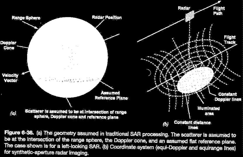
27 27 of 43 SAR interferometry how does it work? A2 B Radar A1 Antenna 1 Return could be from anywhere on this circle Antenna 2 Return comes from intersection Single antenna SAR Interferometric SAR

28 28 of 43

29 InSAR coherent change detection 29 of 43
30 Satellite sensing 30 of 43


31 SAR image of Gibraltar ERS-1 Synthetic Aperture Radar f: 5.3 GHz P TX : 4.8 kw ant: 10 m x 1 m B: 15.5 MHz Δx = Δy = 30 m f s : 19 MSa/s orbit: 780 km D R : 105 Mb/s Nonlinear internal waves propagating eastwards and oil slicks can be seen. 31 of 43


32 SAR imagery of Venus Magellan SAR parameters Frequency: GHz, Bandwidth: 2.26 MHz Pulse duration: 26.5 μs Antenna : 3.5-m dish Resolution (Δx, Δy): 120 m, 120 m Magellan spacecraft orbiting Venus Launched: May 4, 1989 Arrived at Venus: August 10, 1990 Radio contact lost: October 12, of 43
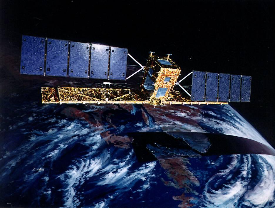

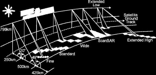
33 33 of 43 Radarsat-1 Synthetic Aperture Radar Overview
34 34 of 43 SAR imaging characteristics Range Res ~ pulse width Azimuth = L / 2 ( 25 m resolution with 3 looks) platform λ (cm) polarization SEASAT 23 HH SIR 23, 5.7, 3.1 pol JERS-1 23 HH ERS-1/2 5.7 VV Radarsat HH ALOS 23 pol Radarsat pol TerraSAR-X 3.1 pol penetration depth = λ 0 ε r 2 π ε r (several meters even at C-band)

35 Single-pass interferometry 35 of 43 Single-pass interferometry. Two antennas offset by known baseline.

36 Topographic map of North America 36 of 43 Shuttle Radar Topography Mission (SRTM) STS-99 Shuttle Endeavour Feb 11 to Feb 22, 2000 Mast length 60 m C and X band SAR systems 30-m horizontal resolution 10 to 16-m vertical resolution


37 37 of 43 Multipass interferometric SAR (InSAR) Same or similar SAR systems image common region at different times. Differences can be attributed to elevation (relief) or horizontal displacements. Third observation needed to isolate elevation effects from displacement effects.


38 Earthquake displacements On December 26, 2003 a magnitude 6.6 earthquake struck the Kerman province in Iran. radar intensity image differential interferogram Multipass ENVISAT SAR data sets from June 11, 2003, December 3, 2003 and January 7, The maximum relative movement change in LOS is about 48 cm and located near the city Bam. ENVISAT SAR launched March 1, 2002 f: GHz orbit: 800 km antenna: 10 m x 1.3 m Δx = Δy = 28 m 320 T/R 38.7 dbm each: 2300 W 38 of 43


 DEM")


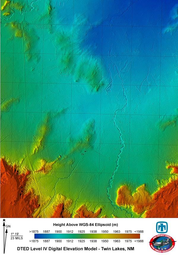
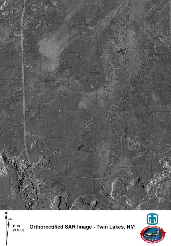
39 Digital elevation mapping with InSAR Interferogram Digital elevation map (DEM) DEM draped with SAR amplitude data Image covers 18.1 km in azimuth, 26.8 km in range. The azimuth direction is horizontal. 39 of 43


40 40 of 43 Surface velocity mapping with InSAR Multipass InSAR mapping of horizontal displacement provides surface velocities. Filchner Ice Stream, Antarctica Petermann Glacier, Greenland
 to avoid spectrum use issues.")
. Meridian UAV Take-off weight: 1080 lbs Wingspan: 26.")
41 41 of 43 Future directions System refinements Eight-channel digitizer (no more time-multiplexing) (6 db improvement) Reduced bandwidth from 180 MHz to 80 MHz (140 to 220 MHz) to avoid spectrum use issues. Signal processing Produce more accurate DEM using interferometry. Produce 3-D SAR maps showing topography and backscattering. Platforms Migrate system to airborne platforms (Twin Otter, UAV). Meridian UAV Take-off weight: 1080 lbs Wingspan: 26.4 ft Range: 1750 km Endurance: 13 hrs Payload: 55 kg


42 42 of 43 Greenland 2008 Jakobshavn Isbrae and its inland drainage area Extensive airborne campaign and surface-based effort vicinity NEEM coring site


43 43 of 43
Microwave Remote Sensing (1)
") Microwave Remote Sensing (1) Microwave sensing encompasses both active and passive forms of remote sensing. The microwave portion of the spectrum covers the range from approximately 1cm to 1m in wavelength.
Microwave Remote Sensing (1) Microwave sensing encompasses both active and passive forms of remote sensing. The microwave portion of the spectrum covers the range from approximately 1cm to 1m in wavelength.
Remote Sensing. Ch. 3 Microwaves (Part 1 of 2)
") Remote Sensing Ch. 3 Microwaves (Part 1 of 2) 3.1 Introduction 3.2 Radar Basics 3.3 Viewing Geometry and Spatial Resolution 3.4 Radar Image Distortions 3.1 Introduction Microwave (1cm to 1m in wavelength)
Remote Sensing Ch. 3 Microwaves (Part 1 of 2) 3.1 Introduction 3.2 Radar Basics 3.3 Viewing Geometry and Spatial Resolution 3.4 Radar Image Distortions 3.1 Introduction Microwave (1cm to 1m in wavelength)
MULTI-CHANNEL SAR EXPERIMENTS FROM THE SPACE AND FROM GROUND: POTENTIAL EVOLUTION OF PRESENT GENERATION SPACEBORNE SAR
 3 nd International Workshop on Science and Applications of SAR Polarimetry and Polarimetric Interferometry POLinSAR 2007 January 25, 2007 ESA/ESRIN Frascati, Italy MULTI-CHANNEL SAR EXPERIMENTS FROM THE
Active and Passive Microwave Remote Sensing
 Active and Passive Microwave Remote Sensing Passive remote sensing system record EMR that was reflected (e.g., blue, green, red, and near IR) or emitted (e.g., thermal IR) from the surface of the Earth.
Active and Passive Microwave Remote Sensing
 Active and Passive Microwave Remote Sensing Passive remote sensing system record EMR that was reflected (e.g., blue, green, red, and near IR) or emitted (e.g., thermal IR) from the surface of the Earth.
Microwave Remote Sensing
 Provide copy on a CD of the UCAR multi-media tutorial to all in class. Assign Ch-7 and Ch-9 (for two weeks) as reading material for this class. HW#4 (Due in two weeks) Problems 1,2,3 and 4 (Chapter 7)
Introduction Active microwave Radar
 RADAR Imaging Introduction 2 Introduction Active microwave Radar Passive remote sensing systems record electromagnetic energy that was reflected or emitted from the surface of the Earth. There are also
Synthetic aperture RADAR (SAR) principles/instruments October 31, 2018
 principles/instruments October 31, 2018") GEOL 1460/2461 Ramsey Introduction to Remote Sensing Fall, 2018 Synthetic aperture RADAR (SAR) principles/instruments October 31, 2018 I. Reminder: Upcoming Dates lab #2 reports due by the start of next
GEOL 1460/2461 Ramsey Introduction to Remote Sensing Fall, 2018 Synthetic aperture RADAR (SAR) principles/instruments October 31, 2018 I. Reminder: Upcoming Dates lab #2 reports due by the start of next
Ultra-Wideband Radars for Measurements Over Land and Sea Ice
 Ultra-Wideband Radars for Measurements Over Land and Sea Ice R. Hale, H. Miller, S. Gogineni, J.-B. Yan, F. Rodriguez-Morales, C. Leuschen, Z. Wang, J. Paden, D. Gomez-Garcia, T. Binder, D. Steinhage,
ESA Radar Remote Sensing Course ESA Radar Remote Sensing Course Radar, SAR, InSAR; a first introduction
 Radar, SAR, InSAR; a first introduction Ramon Hanssen Delft University of Technology The Netherlands r.f.hanssen@tudelft.nl Charles University in Prague Contents Radar background and fundamentals Imaging
CEGEG046 / GEOG3051 Principles & Practice of Remote Sensing (PPRS) 8: RADAR 1
 8: RADAR 1") CEGEG046 / GEOG3051 Principles & Practice of Remote Sensing (PPRS) 8: RADAR 1 Dr. Mathias (Mat) Disney UCL Geography Office: 113, Pearson Building Tel: 7670 05921 Email: mdisney@ucl.geog.ac.uk www.geog.ucl.ac.uk/~mdisney
CEGEG046 / GEOG3051 Principles & Practice of Remote Sensing (PPRS) 8: RADAR 1 Dr. Mathias (Mat) Disney UCL Geography Office: 113, Pearson Building Tel: 7670 05921 Email: mdisney@ucl.geog.ac.uk www.geog.ucl.ac.uk/~mdisney
Principles of Remote Sensing. Shuttle Radar Topography Mission S R T M. Michiel Damen. Dept. Earth Systems Analysis
 Principles of Remote Sensing Shuttle Radar Topography Mission S R T M Michiel Damen Dept. Earth Systems Analysis Contents Present problems with DEMs Advantage of SRTM Cell size Mission and system Radar
ACTIVE SENSORS RADAR
 ACTIVE SENSORS RADAR RADAR LiDAR: Light Detection And Ranging RADAR: RAdio Detection And Ranging SONAR: SOund Navigation And Ranging Used to image the ocean floor (produce bathymetic maps) and detect objects
Earth Observation and Sensing Technologies: a focus on Radar Imaging Developments. Riccardo Lanari
 Earth Observation and Sensing Technologies: a focus on Radar Imaging Developments Riccardo Lanari Institute for Electromagnetic Sensing of the Environment (IREA) National Research Council of Italy (CNR)
EE 529 Remote Sensing Techniques. Introduction
 EE 529 Remote Sensing Techniques Introduction Course Contents Radar Imaging Sensors Imaging Sensors Imaging Algorithms Imaging Algorithms Course Contents (Cont( Cont d) Simulated Raw Data y r Processing
Synthetic Aperture Radar
 Synthetic Aperture Radar Picture 1: Radar silhouette of a ship, produced with the ISAR-Processor of the Ocean Master A Synthetic Aperture Radar (SAR), or SAR, is a coherent mostly airborne or spaceborne
RADAR REMOTE SENSING
 RADAR REMOTE SENSING Jan G.P.W. Clevers & Steven M. de Jong Chapter 8 of L&K 1 Wave theory for the EMS: Section 1.2 of L&K E = electrical field M = magnetic field c = speed of light : propagation direction
RADAR (RAdio Detection And Ranging)
") RADAR (RAdio Detection And Ranging) CLASSIFICATION OF NONPHOTOGRAPHIC REMOTE SENSORS PASSIVE ACTIVE DIGITAL CAMERA THERMAL (e.g. TIMS) VIDEO CAMERA MULTI- SPECTRAL SCANNERS VISIBLE & NIR MICROWAVE Real
RADAR (RAdio Detection And Ranging) CLASSIFICATION OF NONPHOTOGRAPHIC REMOTE SENSORS PASSIVE ACTIVE DIGITAL CAMERA THERMAL (e.g. TIMS) VIDEO CAMERA MULTI- SPECTRAL SCANNERS VISIBLE & NIR MICROWAVE Real
Introduction to Imaging Radar INF-GEO 4310
 Introduction to Imaging Radar INF-GEO 4310 22.9.2011 Literature Contact: yoann.paichard@ffi.no Suggested readings: Fundamentals of Radar Signal Processing, M.A. Richards, McGraw-Hill, 2005 High Resolution
A bluffer s guide to Radar
 A bluffer s guide to Radar Andy French December 2009 We may produce at will, from a sending station, an electrical effect in any particular region of the globe; (with which) we may determine the relative
Specificities of Near Nadir Ka-band Interferometric SAR Imagery
 Specificities of Near Nadir Ka-band Interferometric SAR Imagery Roger Fjørtoft, Alain Mallet, Nadine Pourthie, Jean-Marc Gaudin, Christine Lion Centre National d Etudes Spatiales (CNES), France Fifamé
Acknowledgment. Process of Atmospheric Radiation. Atmospheric Transmittance. Microwaves used by Radar GMAT Principles of Remote Sensing
 GMAT 9600 Principles of Remote Sensing Week 4 Radar Background & Surface Interactions Acknowledgment Mike Chang Natural Resources Canada Process of Atmospheric Radiation Dr. Linlin Ge and Prof Bruce Forster
Synthetic Aperture Radar Interferometry (InSAR) Technique (Lecture I- Tuesday 11 May 2010)
 Technique (Lecture I- Tuesday 11 May 2010)") Synthetic Aperture Radar Interferometry () Technique (Lecture I- Tuesday 11 May 2010) ISNET/CRTEAN Training Course on Synthetic Aperture Radar (SAR) Imagery: Processing, Interpretation and Applications
Synthetic Aperture Radar Interferometry () Technique (Lecture I- Tuesday 11 May 2010) ISNET/CRTEAN Training Course on Synthetic Aperture Radar (SAR) Imagery: Processing, Interpretation and Applications
Design of an Airborne SLAR Antenna at X-Band
 Design of an Airborne SLAR Antenna at X-Band Markus Limbach German Aerospace Center (DLR) Microwaves and Radar Institute Oberpfaffenhofen WFMN 2007, Markus Limbach, Folie 1 Overview Applications of SLAR
GISMO: Arctic 07 Fall Deployment of the NASA P-3 to Greenland. Field Report. Submitted to the NASA Earth Science and Technology Office
 GISMO: Arctic 07 Fall Deployment of the NASA P-3 to Greenland Field Report Submitted to the NASA Earth Science and Technology Office Prepared by: K. Jezek, S. Gogineni, F. Rodriguez, A. Hoch and J. Sonntag
Rec. ITU-R P RECOMMENDATION ITU-R P *
 Rec. ITU-R P.682-1 1 RECOMMENDATION ITU-R P.682-1 * PROPAGATION DATA REQUIRED FOR THE DESIGN OF EARTH-SPACE AERONAUTICAL MOBILE TELECOMMUNICATION SYSTEMS (Question ITU-R 207/3) Rec. 682-1 (1990-1992) The
SARscape Modules for ENVI
 Visual Information Solutions SARscape Modules for ENVI Read, process, analyze, and output products from SAR data. ENVI. Easy to Use Tools. Proven Functionality. Fast Results. DEM, based on TerraSAR-X-1
Introduction to Radar
 National Aeronautics and Space Administration ARSET Applied Remote Sensing Training http://arset.gsfc.nasa.gov @NASAARSET Introduction to Radar Jul. 16, 2016 www.nasa.gov Objective The objective of this
THE NASA/JPL AIRBORNE SYNTHETIC APERTURE RADAR SYSTEM. Yunling Lou, Yunjin Kim, and Jakob van Zyl
 THE NASA/JPL AIRBORNE SYNTHETIC APERTURE RADAR SYSTEM Yunling Lou, Yunjin Kim, and Jakob van Zyl Jet Propulsion Laboratory California Institute of Technology 4800 Oak Grove Drive, MS 300-243 Pasadena,
INTRODUCTION TO RADAR SIGNAL PROCESSING
 INTRODUCTION TO RADAR SIGNAL PROCESSING Christos Ilioudis University of Strathclyde c.ilioudis@strath.ac.uk Overview History of Radar Basic Principles Principles of Measurements Coherent and Doppler Processing
MODULE 9 LECTURE NOTES 2 ACTIVE MICROWAVE REMOTE SENSING
 MODULE 9 LECTURE NOTES 2 ACTIVE MICROWAVE REMOTE SENSING 1. Introduction Satellite sensors are capable of actively emitting microwaves towards the earth s surface. An active microwave system transmits
Lecture 1 INTRODUCTION. Dr. Aamer Iqbal Bhatti. Radar Signal Processing 1. Dr. Aamer Iqbal Bhatti
 Lecture 1 INTRODUCTION 1 Radar Introduction. A brief history. Simplified Radar Block Diagram. Two basic Radar Types. Radar Wave Modulation. 2 RADAR The term radar is an acronym for the phrase RAdio Detection
Motion Detection Using TanDEM-X Along-Track Interferometry
 Motion Detection Using TanDEM-X Along-Track Interferometry Steffen Suchandt and Hartmut Runge German Aerospace Center, Remote Sensing Technology Institute TanDEM-X Science Meeting, June 12th, 2013 Outline
CNES PRIORITIES IN POLAR AND CRYOSPHERE RESEARCH
 Polar Space Task Group 3rd Session CNES PRIORITIES IN POLAR AND CRYOSPHERE RESEARCH Juliette Lambin, Steven Hosford Wednesday, May 22th, 2013 Paris, France 1 OUTLINE CNES MISSIONS FOR POLAR/CRYOSPHERE
A Bistatic HF Radar for Current Mapping and Robust Ship Tracking
 A Bistatic HF Radar for Current Mapping and Robust Ship Tracking Dennis Trizna Imaging Science Research, Inc. V. 703-801-1417 dennis @ isr-sensing.com www.isr-sensing.com Objective: Develop methods for
Chapter 6 Spaceborne SAR Antennas for Earth Science
 Chapter 6 Spaceborne SAR Antennas for Earth Science Yunjin Kim and Rolando L. Jordan 6.1 Introduction Before the development of the first synthetic aperture radar (SAR) antenna flown in space, Jet Propulsion
Concept Design of Space-Borne Radars for Tsunami Detection
 Concept Design of Space-Borne Radars for Tsunami Detection DLR German Aerospace Agency +Microwaves and Radar Institute *Remote Sensing Institute +Michele Galletti +Gerhard Krieger +Nicolas Marquart +Thomas
Passive Microwave Sensors LIDAR Remote Sensing Laser Altimetry. 28 April 2003
 Passive Microwave Sensors LIDAR Remote Sensing Laser Altimetry 28 April 2003 Outline Passive Microwave Radiometry Rayleigh-Jeans approximation Brightness temperature Emissivity and dielectric constant
The Tandem-L Formation
 The Tandem-L Formation G. Krieger, I. Hajnsek, K. Papathanassiou, M. Eineder, M. Younis, F. De Zan, P. Prats, S. Huber, M. Werner, A. Freeman +, P. Rosen +, S. Hensley +, W. Johnson +, L. Veilleux +, B.
ATS 351 Lecture 9 Radar
 ATS 351 Lecture 9 Radar Radio Waves Electromagnetic Waves Consist of an electric field and a magnetic field Polarization: describes the orientation of the electric field. 1 Remote Sensing Passive vs Active
SODAR- sonic detecting and ranging
 Active Remote Sensing of the PBL Immersed vs. remote sensors Active vs. passive sensors RADAR- radio detection and ranging WSR-88D TDWR wind profiler SODAR- sonic detecting and ranging minisodar RASS RADAR
TanDEM-X: Mission Status & Scientific Contribution
 TanDEM-X: Mission Status & Scientific Contribution Irena Hajnsek 1/2, Gerhard Krieger 1, Kostas Papathanassiou 1, Stefan Baumgartner 1, Marc Rodriguez-Cassola 1, Pau Prats 1, Maria Sanjuan Ferrer 1, Florian
Lecture 8. Radar Equation. Dr. Aamer Iqbal Bhatti. Radar Signal Processing. Dr. Aamer Iqbal Bhatti
 ecture 8 Radar Equation 1 Power received from a point target in absence of noise. PT G PR W / m (4 ) R If the received power from interfering sources is known, the signal-to-interference ratio is found
Monitoring the Earth Surface from space
 Monitoring the Earth Surface from space Picture of the surface from optical Imagery, i.e. obtained by telescopes or cameras operating in visual bandwith. Shape of the surface from radar imagery Surface
Radar Imaging Wavelengths
 A Basic Introduction to Radar Remote Sensing ~~~~~~~~~~ Rev. Ronald J. Wasowski, C.S.C. Associate Professor of Environmental Science University of Portland Portland, Oregon 3 November 2015 Radar Imaging
Final Examination. 22 April 2013, 9:30 12:00. Examiner: Prof. Sean V. Hum. All non-programmable electronic calculators are allowed.
 UNIVERSITY OF TORONTO FACULTY OF APPLIED SCIENCE AND ENGINEERING The Edward S. Rogers Sr. Department of Electrical and Computer Engineering ECE 422H1S RADIO AND MICROWAVE WIRELESS SYSTEMS Final Examination
RADAR DEVELOPMENT BASIC CONCEPT OF RADAR WAS DEMONSTRATED BY HEINRICH. HERTZ VERIFIED THE MAXWELL RADAR.
 1 RADAR WHAT IS RADAR? RADAR (RADIO DETECTION AND RANGING) IS A WAY TO DETECT AND STUDY FAR OFF TARGETS BY TRANSMITTING A RADIO PULSE IN THE DIRECTION OF THE TARGET AND OBSERVING THE REFLECTION OF THE
Synthetic Aperture Radar. Hugh Griffiths THALES/Royal Academy of Engineering Chair of RF Sensors University College London
 Synthetic Aperture Radar Hugh Griffiths THALES/Royal Academy of Engineering Chair of RF Sensors University College London CEOI Training Workshop Designing and Delivering and Instrument Concept 15 March
Environmental Impact Assessment of Mining Subsidence by Using Spaceborne Radar Interferometry
 Environmental Impact Assessment of Mining Subsidence by Using Spaceborne Radar Interferometry Hsing-Chung CHANG, Linlin GE and Chris RIZOS, Australia Key words: Mining Subsidence, InSAR, DInSAR, DEM. SUMMARY
SAR Remote Sensing (Microwave Remote Sensing)
") iirs SAR Remote Sensing (Microwave Remote Sensing) Synthetic Aperture Radar Shashi Kumar shashi@iirs.gov.in Electromagnetic Radiation Electromagnetic radiation consists of an electrical field(e) which
iirs SAR Remote Sensing (Microwave Remote Sensing) Synthetic Aperture Radar Shashi Kumar shashi@iirs.gov.in Electromagnetic Radiation Electromagnetic radiation consists of an electrical field(e) which
Fundamental Concepts of Radar
 Fundamental Concepts of Radar Dr Clive Alabaster & Dr Evan Hughes White Horse Radar Limited Contents Basic concepts of radar Detection Performance Target parameters measurable by a radar Primary/secondary
GMES Sentinel-1 Transponder Development
 GMES Sentinel-1 Transponder Development Paul Snoeij Evert Attema Björn Rommen Nicolas Floury Malcolm Davidson ESA/ESTEC, European Space Agency, Noordwijk, The Netherlands Outline 1. GMES Sentinel-1 overview
remote sensing? What are the remote sensing principles behind these Definition
 Introduction to remote sensing: Content (1/2) Definition: photogrammetry and remote sensing (PRS) Radiation sources: solar radiation (passive optical RS) earth emission (passive microwave or thermal infrared
UAVSAR in Africa. Quality Assurance and Preliminary Results. Brian Hawkins, UAVSAR Team
 Photo by Sassan Saatchi UAVSAR in Africa Quality Assurance and Preliminary Results Brian Hawkins, UAVSAR Team CEOS SAR Cal/Val Workshop 2016 Copyright 2016 California Institute of Technology. Government
Lecture 3 SIGNAL PROCESSING
 Lecture 3 SIGNAL PROCESSING Pulse Width t Pulse Train Spectrum of Pulse Train Spacing between Spectral Lines =PRF -1/t 1/t -PRF/2 PRF/2 Maximum Doppler shift giving unambiguous results should be with in
Interferometric Cartwheel 1
 The Interferometric CartWheel A wheel of passive radar microsatellites for upgrading existing SAR projects D. Massonnet, P. Ultré-Guérard (DPI/EOT) E. Thouvenot (DTS/AE/INS/IR) Interferometric Cartwheel
Sources of Geographic Information
 Sources of Geographic Information Data properties: Spatial data, i.e. data that are associated with geographic locations Data format: digital (analog data for traditional paper maps) Data Inputs: sampled
Introduction to Microwave Remote Sensing
 Introduction to Microwave Remote Sensing lain H. Woodhouse The University of Edinburgh Scotland Taylor & Francis Taylor & Francis Group Boca Raton London New York A CRC title, part of the Taylor & Francis
Remote Sensing: John Wilkin IMCS Building Room 211C ext 251. Active microwave systems (1) Satellite Altimetry
 Satellite Altimetry") Remote Sensing: John Wilkin wilkin@marine.rutgers.edu IMCS Building Room 211C 732-932-6555 ext 251 Active microwave systems (1) Satellite Altimetry Active microwave instruments Scatterometer (scattering
Remote Sensing: John Wilkin wilkin@marine.rutgers.edu IMCS Building Room 211C 732-932-6555 ext 251 Active microwave systems (1) Satellite Altimetry Active microwave instruments Scatterometer (scattering
Remote Sensing 1 Principles of visible and radar remote sensing & sensors
 Remote Sensing 1 Principles of visible and radar remote sensing & sensors Nick Barrand School of Geography, Earth & Environmental Sciences University of Birmingham, UK Field glaciologist collecting data
Imaging radar Imaging radars provide map-like coverage to one or both sides of the aircraft.
 CEE 6100 / CSS 6600 Remote Sensing Fundamentals 1 Imaging radar Imaging radars provide map-like coverage to one or both sides of the aircraft. Acronyms: RAR real aperture radar ("brute force", "incoherent")
Multi Band Passive Forward Scatter Radar
 Multi Band Passive Forward Scatter Radar S. Hristov, A. De Luca, M. Gashinova, A. Stove, M. Cherniakov EESE, University of Birmingham Birmingham, B15 2TT, UK m.cherniakov@bham.ac.uk Outline Multi-Band
Radar Methods General Overview
 Environmental and Exploration Geophysics II Radar Methods General Overview tom.h.wilson tom.wilson@mail.wvu.edu Department of Geology and Geography West Virginia University Morgantown, WV Brown (2004)
Wave Sensing Radar and Wave Reconstruction
 Applied Physical Sciences Corp. 475 Bridge Street, Suite 100, Groton, CT 06340 (860) 448-3253 www.aphysci.com Wave Sensing Radar and Wave Reconstruction Gordon Farquharson, John Mower, and Bill Plant (APL-UW)
The Delay-Doppler Altimeter
 Briefing for the Coastal Altimetry Workshop The Delay-Doppler Altimeter R. K. Raney Johns Hopkins University Applied Physics Laboratory 05-07 February 2008 1 What is a Delay-Doppler altimeter? Precision
School of Rural and Surveying Engineering National Technical University of Athens
 Laboratory of Photogrammetry National Technical University of Athens Combined use of spaceborne optical and SAR data Incompatible data sources or a useful procedure? Charalabos Ioannidis, Dimitra Vassilaki
China. France Oceanography S A T. Overview of the near-real time wave products of the CFOSAT mission. e l l i t e
 China Overview of the near-real time wave products of the CFOSAT mission C. Tison (1), D. Hauser (2), S. Guibert (1), T. Amiot (1), L. Aouf (3), J.M. Lefèvre (3), B. Chapron (5), N. Corcoral (1), P. Castillan
Polarisation Capabilities and Status of TerraSAR-X
 Polarisation Capabilities and Status of TerraSAR-X Irena Hajnsek, Josef Mittermayer, Stefan Buckreuss, Kostas Papathanassiou German Aerospace Center Microwaves and Radar Institute irena.hajnsek@dlr.de
Prototype Software-based Receiver for Remote Sensing using Reflected GPS Signals. Dinesh Manandhar The University of Tokyo
 Prototype Software-based Receiver for Remote Sensing using Reflected GPS Signals Dinesh Manandhar The University of Tokyo dinesh@qzss.org 1 Contents Background Remote Sensing Capability System Architecture
RADAR INTERFEROMETRY FOR SAFE COAL MINING IN CHINA
 RADAR INTERFEROMETRY FOR SAFE COAL MINING IN CHINA L. Ge a, H.-C. Chang a, A. H. Ng b and C. Rizos a Cooperative Research Centre for Spatial Information School of Surveying & Spatial Information Systems,
A Bistatic HF Radar for Current Mapping and Robust Ship Tracking
 A Bistatic HF Radar for Current Mapping and Robust Ship Tracking D. B. Trizna Imaging Science Research, Inc. 6103B Virgo Court Burke, VA, 22015 USA Abstract- A bistatic HF radar has been developed for
L-BAND ICE-PENETRATING RADAR ON BOARD A SMALL SATELLITE
 L-BAND ICE-PENETRATING RADAR ON BOARD A SMALL SATELLITE Anoop Parthasarathy Mtech. Digital Signal Processing Centre for Emerging Technologies Jain University ACKNOWLEDGEMENTS My sincere thanks to Dr. G.
Introduction Objective and Scope p. 1 Generic Requirements p. 2 Basic Requirements p. 3 Surveillance System p. 3 Content of the Book p.
 Preface p. xi Acknowledgments p. xvii Introduction Objective and Scope p. 1 Generic Requirements p. 2 Basic Requirements p. 3 Surveillance System p. 3 Content of the Book p. 4 References p. 6 Maritime
SATELLITE OCEANOGRAPHY
 SATELLITE OCEANOGRAPHY An Introduction for Oceanographers and Remote-sensing Scientists I. S. Robinson Lecturer in Physical Oceanography Department of Oceanography University of Southampton JOHN WILEY
The Potential of Synthetic Aperture Sonar in seafloor imaging
 The Potential of Synthetic Aperture Sonar in seafloor imaging CM 2000/T:12 Ron McHugh Heriot-Watt University, Department of Computing and Electrical Engineering, Edinburgh, EH14 4AS, Scotland, U.K. Tel:
Detection of Multipath Propagation Effects in SAR-Tomography with MIMO Modes
 Detection of Multipath Propagation Effects in SAR-Tomography with MIMO Modes Tobias Rommel, German Aerospace Centre (DLR), tobias.rommel@dlr.de, Germany Gerhard Krieger, German Aerospace Centre (DLR),
LE/ESSE Payload Design
 LE/ESSE4360 - Payload Design 3.4 Spacecraft Sensors - Radar Sensors Earth, Moon, Mars, and Beyond Dr. Jinjun Shan, Professor of Space Engineering Department of Earth and Space Science and Engineering Room
Bistatic/Monostatic Synthetic Aperture Radar for Ice Sheet Measurements
 Bistatic/Monostatic Snthetic Aperture Radar for Ice Sheet Measurements John Paden MS Thesis Defense April 18, 003 Committee Chairperson: Dr. Chris Allen Committee Members: Dr. Prasad Gogineni Dr. Glenn
Executive Summary. Doc. No.: EA-XS Issue: 1 Rev. 0 Date: Name Date Signature
 Project: Feasibility Study on Satellite-Unmanned Airborne Systems Cooperative Approaches for the Improvement of all- Weather Day and Night Operations Title: Executive Summary Doc. No.: EA-XS Date: 12.10.2009
Satellite Navigation (and positioning)
") Satellite Navigation (and positioning) Picture: ESA AE4E08 Instructors: Sandra Verhagen, Hans van der Marel, Christian Tiberius Course 2010 2011, lecture 1 Today s topics Course organisation Course contents
Satellite Navigation (and positioning) Picture: ESA AE4E08 Instructors: Sandra Verhagen, Hans van der Marel, Christian Tiberius Course 2010 2011, lecture 1 Today s topics Course organisation Course contents
10 Radar Imaging Radar Imaging
 10 Radar Imaging Active sensors provide their own source of energy to illuminate the target. Active sensors are generally divided into two distinct categories: imaging and non-imaging. The most common
Antenna Design and Site Planning Considerations for MIMO
 Antenna Design and Site Planning Considerations for MIMO Steve Ellingson Mobile & Portable Radio Research Group (MPRG) Dept. of Electrical & Computer Engineering Virginia Polytechnic Institute & State
Active microwave systems (1) Satellite Altimetry
 Satellite Altimetry") Remote Sensing: John Wilkin Active microwave systems (1) Satellite Altimetry jwilkin@rutgers.edu IMCS Building Room 214C 732-932-6555 ext 251 Active microwave instruments Scatterometer (scattering from
Remote Sensing: John Wilkin Active microwave systems (1) Satellite Altimetry jwilkin@rutgers.edu IMCS Building Room 214C 732-932-6555 ext 251 Active microwave instruments Scatterometer (scattering from
Remote Sensing: John Wilkin IMCS Building Room 211C ext 251. Active microwave systems (1) Satellite Altimetry
 Satellite Altimetry") Remote Sensing: John Wilkin wilkin@marine.rutgers.edu IMCS Building Room 211C 732-932-6555 ext 251 Active microwave systems (1) Satellite Altimetry Active microwave instruments Scatterometer (scattering
Remote Sensing: John Wilkin wilkin@marine.rutgers.edu IMCS Building Room 211C 732-932-6555 ext 251 Active microwave systems (1) Satellite Altimetry Active microwave instruments Scatterometer (scattering
Study of Polarimetric Calibration for Circularly Polarized Synthetic Aperture Radar
 Study of Polarimetric Calibration for Circularly Polarized Synthetic Aperture Radar 2016.09.07 CEOS WORKSHOP 2016 Yuta Izumi, Sevket Demirci, Mohd Zafri Baharuddin, and Josaphat Tetuko Sri Sumantyo JOSAPHAT
European Space Agency and IPY
 European Space Agency and IPY ESA supports IPY 2007-2008 activities: First ESA step was a dedicated Announcement Opportunity (AO) for EO data provision in support IPY, released in 2006, with data provision
RADAR CHAPTER 3 RADAR
 RADAR CHAPTER 3 RADAR RDF becomes Radar 1. As World War II approached, scientists and the military were keen to find a method of detecting aircraft outside the normal range of eyes and ears. They found
PALSAR SCANSAR SCANSAR Interferometry
 PALSAR SCANSAR SCANSAR Interferometry Masanobu Shimada Japan Aerospace Exploration Agency Earth Observation Research Center ALOS PI symposium, Greece Nov. 6 2008 1 Introduction L-band PALSAR strip mode
IBIS range. GeoRadar Division. GeoRadar Division. Static and Dynamic Monitoring of Civil Engineering Structures by Microwave Interferometry
 Static and Dynamic Monitoring of Civil Engineering Structures by Microwave Interferometry Garry Spencer and Mark Bell 1 PRODUCTS IBIS range APPLICATIONS IBIS - FL LANDSLIDE & DAM MONITORING IBIS - FM SLOPE
RECOMMENDATION ITU-R S.1341*
 Rec. ITU-R S.1341 1 RECOMMENDATION ITU-R S.1341* SHARING BETWEEN FEEDER LINKS FOR THE MOBILE-SATELLITE SERVICE AND THE AERONAUTICAL RADIONAVIGATION SERVICE IN THE SPACE-TO-EARTH DIRECTION IN THE BAND 15.4-15.7
A new Sensor for the detection of low-flying small targets and small boats in a cluttered environment
 UNCLASSIFIED /UNLIMITED Mr. Joachim Flacke and Mr. Ryszard Bil EADS Defence & Security Defence Electronics Naval Radar Systems (OPES25) Woerthstr 85 89077 Ulm Germany joachim.flacke@eads.com / ryszard.bil@eads.com
SAR Training Course, MCST, Kalkara, Malta, November SAR Maritime Applications. History and Basics
 SAR Maritime Applications History and Basics Martin Gade Uni Hamburg, Institut für Meereskunde SAR Maritime Applications Thursday, 13 Nov.: 1 - History & Basics Introduction Radar/SAR History Basics Scatterometer
SYSTEM 5900 SIDE SCAN SONAR
 SYSTEM 5900 SIDE SCAN SONAR HIGH-RESOLUTION, DYNAMICALLY FOCUSED, MULTI-BEAM SIDE SCAN SONAR Klein Marine System s 5900 sonar is the flagship in our exclusive family of multi-beam technology-based side
Hardware Modeling and Machining for UAV- Based Wideband Radar
 Hardware Modeling and Machining for UAV- Based Wideband Radar By Ryan Tubbs Abstract The Center for Remote Sensing of Ice Sheets (CReSIS) at the University of Kansas is currently implementing wideband
Generation of Fine Resolution DEM at Test Areas in Alaska Using ERS SAR Tandem Pairs and Precise Orbital Data *
 Generation of Fine Resolution DEM at Test Areas in Alaska Using ERS SAR Tandem Pairs and Precise Orbital Data * O. Lawlor, T. Logan, R. Guritz, R. Fatland, S. Li, Z. Wang, and C. Olmsted Alaska SAR Facility
Radar Depth Sounder Processing and Digital Thickness Map of Outlet Glaciers
 Radar Depth Sounder Processing and Digital Thickness Map of Outlet Glaciers By Harish N. Ramamoorthy Bachelor of Engineering, Instrumentation and Control, University of Madras, Chennai, India, 2001 Submitted
SAR Interferometry Capabilities of Canada's planned SAR Satellite Constellation
 SAR Interferometry Capabilities of Canada's planned SAR Satellite Constellation Dirk Geudtner, Guy Séguin,, Ralph Girard Canadian Space Agency RADARSAT Follow-on Program CSA is in the middle of a Phase
Set No.1. Code No: R
 Set No.1 IV B.Tech. I Semester Regular Examinations, November -2008 RADAR SYSTEMS ( Common to Electronics & Communication Engineering and Electronics & Telematics) Time: 3 hours Max Marks: 80 Answer any
Basic Radar Definitions Introduction p. 1 Basic relations p. 1 The radar equation p. 4 Transmitter power p. 9 Other forms of radar equation p.
 Basic Radar Definitions Basic relations p. 1 The radar equation p. 4 Transmitter power p. 9 Other forms of radar equation p. 11 Decibel representation of the radar equation p. 13 Radar frequencies p. 15
Synthetic Aperture Radar (SAR) images features clustering using Fuzzy c- means (FCM) clustering algorithm
 images features clustering using Fuzzy c- means (FCM) clustering algorithm") Article Synthetic Aperture Radar (SAR) images features clustering using Fuzzy c- means (FCM) clustering algorithm Rashid Hussain Faculty of Engineering Science and Technology, Hamdard University, Karachi
Article Synthetic Aperture Radar (SAR) images features clustering using Fuzzy c- means (FCM) clustering algorithm Rashid Hussain Faculty of Engineering Science and Technology, Hamdard University, Karachi