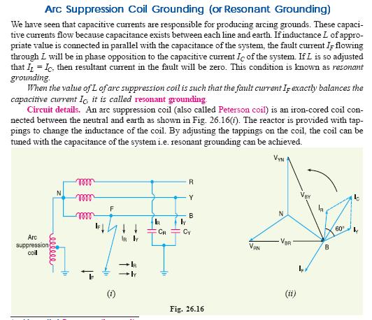
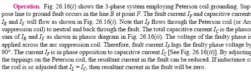
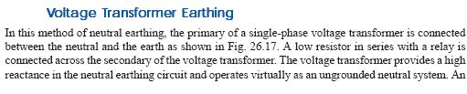
DHANALAKSHMI COLLEGE OF ENGINEERING, CHENNAI 301.
|
|
|
- Nora Preston
- 6 years ago
- Views:
Transcription
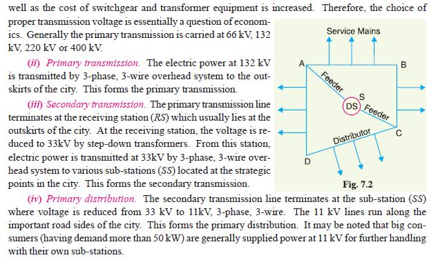
1 DHANALAKSHMI COLLEGE OF ENGINEERING, CHENNAI 301. Sub: Transmission and Distribution Branch: EEE Code: EE2303 Sem: V UNIT I INTRODUCTION PART A 1. What are the components of a power system? The components of power systems are 1. generating stations 2. step up transformer stations 3. transmission lines 4. switching stations 5. step down transformer stations 6. primary distribution lines 7. service transformer banks 8. secondary distribution lines 2. What is meant by transmission and distribution system? A large network which is used to deliver bulk power from power stations to the load centers and large industrial consumers is called distribution system. 3. What are the transmission level voltages we have in India? Primary transmission level voltage is 132 KV, 220KV or 400KV and secondary transmission level voltage is 33KV or 66KV. 4. What are the various levels of generation in India? 3.3KV, 6.6KV, 11KV or 33KV. 5. What are the various levels of primary distribution in India? 11KV, 6.6KV or 3.3KV. 6. What is the usable voltage for secondary distribution? 415V & 240 V (415 volts for 3-phase loads and 240 volts for 1-phase loads) 7. What is a one-line diagram? Schematic representation of the elements of electric power system is called as one line diagram. 8. What is meant by primary and secondary transmission? Transmission of electric power at 132KV by 3 phase 3 wire overhead system is known as secondary transmission. Transmission of electric power at 33KV by 3 phase 3 wire overhead system is known as secondary transmission. Department of EEE Page 1
2 9. What is meant by primary and secondary distributions? The secondary transmission lines terminates at the substations where voltage is reduced from 333KV to 11KV lines which run along the road sides of the city forms the primary distribution. A primary distribution line terminates at the distributing substations where voltage is reduced from 11KV to 400 volts. Thus 3 phase 4 wire system which connect the distributing substation and the consumer point forms the secondary distribution. 10. Distinguish between a feeder and a distributor. SI.NO Feeder Distributor 1. a) Feeders are conductors or transmission lines which carry current from the stations to the feeding points. Feeders terminate into distributors b) No tapping is taken from the feeders. 2. Current carrying capacity plays a major role in designing a feeder. 3. Current loading remains the same along its length. So distributor is also a conductor from which current is tapped off for the supply to the consumer. Whereas voltage drop plays a major role in designing a distributor. Current loading factor varies along its length. 11. Define the term distributor? Distributor is a conductor from which current is tapped off for the supply to the consumers. Feeders terminate into distributor. 12. What is a feeder? (Nov 2012) Feeder is a conductor or transmission line which transmits current from the generating stations to different distributing substations. 13. Why is electrical power preferably to be transmitted at a high voltage? Electrical power is transmitted at high voltage because, 1.) It reduces the volume of conductor material used. 2.) It increases transmission efficiency. 3.) It decreases line drop. 14. What are the advantages of the HVDC transmission system over HVAC transmission? Advantages of HVDC transmission are 1.) It requires only two conductors as compared to three for ac transmission. Department of EEE Page 2
3 2.) There is no inductance, capacitance, phase displacement and surge problems in DC transmission. 3.) Due to the absence of inductance, the voltage drop in a DC transmission line is less than AC line for the same load and sending end voltage. Hence DC transmission has a better voltage regulation. 4.) There is no skin effect in a DC system. Therefore entire cress section of conductor is utilized. 5.) For the same working voltage the potential stress on the insulation is less in case of DC system than that in AC system. Therefore DC line requires less insulation. 6.) DC line has less corona loss and reduced interference with communication circuits. 7.) HVDC transmission line is free from dielectric loss, particularly in the case of cables. 8.) No stabilizer is required for HVDC transmission over long distances. 15. What are the demerits of HVDC transmission? 1.) Electric power cannot be generated at high DC voltages 2.) The DC voltages cannot be stepped up for transmission of power at high voltages. 3.) The DC switches and circuit breakers have their own limitations. 16. What are the disadvantages high voltage AC transmissions? 1.) An AC line requires more copper than a DC line 2.) The construction of an AC line is more complicated than a DC transmission line. 3.) Due to skin effect in the ac system the effective resistance of the line is increased. 4.) An AC line has capacitance. Therefore there is a continuous loss of power due to charging current even when the line is open. 17. What are terminal equipments necessary in HVDC system? The terminal equipments necessary in HVDC system are converters, inverters mercury are valves, thyristors etc. 18. Why all transmission and distribution systems are 3 phase systems? A 3 phase A.C circuit using the same size conductors as the single phase circuit can carry three times the power which can be carried by a 1 phase circuit and uses 3 conductors for the 2 phases and one conductor for the neutral. Thus a 3 phase circuit is more economical than a 1 phase circuit in terms of initial cost as well as the losses. Therefore all transmission and distribution systems are 3 phase systems. 19. State the advantages of interconnected systems. Any area fed from one generating station during overload hours can be fed from another power station and thus reserved capacity required is reduced, reliability of supply is increased and efficiency is increased. Department of EEE Page 3
4 20. Mention the limitations of using very high transmission voltage. The increased cost of insulation of conductors. The increased cost of transformers switches gears and other terminal apparatus. 21. Mention the equipments that supply reactive power in HVDC converter stations? AC filters Static shunt capacitors Synchronous condensers StaticVAR compensators. 22. Why DC transmission is economical and preferable over AC transmission for large distances only? Because with larger distances, the saving in cost of DC overhead lines become greater than the additional expenditure on terminal equipment. 23. Why is voltage regulation better in case of DC transmission? Because of absence of inductance in DC systems. 24. What are the advantages of adopting EHV/UHV for transmission of AC electric power? -Reduced line losses -High transmission efficiency -Improved voltage regulation -Reduced conductor material requirement -Flexibility for future system growth -increase in transmission capacity of the line -increase of SIL. 25. Mention the problems associated with an EHV transmission? The problems associated with EHV transmission are corona loss and radio interference, requirements of heavy supporting structures erection difficulties and insulation requirements. 26. What for series and shunt compensation provided in EHV lines? Series compensation is provided to reduce the series reactance of the line so as to improve stability, voltage regulation and transmission efficiency. Shunt compensation is provided to reduce the line susceptance so as to improve the voltage regulation under light load condition. 27. What is the voltage that has been selected for HVDC transmission? ± 500 KV. 28. What is FACTS? Department of EEE Page 4
5 Flexible Alternating Current Transmission System is alternating current transmission systems incorporating power electronic based and other static controllers to enhance controllability and increase power transfer capability 29. State the IEEE definition for TCSC A capacitive reactance compensator which consists of a series capacitor bank shunted by a Thyristor-controlled reactor in order to provide smoothly variable series capacitive reactance. 30. State the IEEE definition for SVC A shunt connected static var generator or absorber whose output is adjusted to exchange capacitive or inductive current so as to maintain or control specific parameters of the electric power system (bus voltages) 31. State the IEEE definition for STATCOM A static synchronous compensator is a static synchronous generator operated as a shunt connected static var compensator whose capacitive or inductive output current can be controlled independent of the AC system voltage. 32. State the IEEE definition for UPFC Unified Power Flow Controller is a combination of static synchronous compensator (STATCOM) and a static series compensator (SSSC) which are coupled via a common DC link, to allow bidirectional flow of real power between the series output terminals of the SSSC and the shunt output terminals of the STATCOM, and are controlled to provide concurrent real and reactive series line compensation without an external electric energy source 33. What is meant by sag? The difference in level between points of supports and the lowest point on the conductor is called sag. 34. Give any two factors that affect sag in an overhead line. (Nov 2012) Wind and Ice loading 35. What are the advantages of high voltage AC transmission? (Nov 2011) 1.) The power can be generated at high voltages. 2.) The maintenance of ac substations is easy and cheaper. 3.) The ac voltage can be stepped up or stepped down by transformer with ease and efficiency. This permits to transmit power at high voltages and distribute it at safe potentials. 36. What is meant by string chart? (Nov 2011) The curves of tension and sag vs temperature is called string chart. 37. What is a feeder? (Nov 2012) Feeder is a conductor or transmission line which transmits current from the generating stations to different distributing substations Department of EEE Page 5


6 PART B 1. Draw the layout of modern system and explain. What is the highest voltage level available in India for EHV transmission? Department of EEE Page 6
7 Department of EEE Page 7


8 38. Give the advantages, disadvantages and applications of HVDC transmission system. (Nov 2012) Department of EEE Page 8
9 APPLICATIONS OF HVDC SYSTEM: The controllability of current-flow through HVDC rectifiers and inverters, their application in connecting unsynchronized networks, and their applications in efficient submarine cables mean that HVDC cables are often used at national boundaries for the exchange of power (in North America, HVDC connections divide much of Canada and the United States into several electrical regions that cross national borders, although the purpose of these connections is still to connect unsynchronized AC grids to each other). Offshore windfarms also require undersea cables, and their turbines are unsynchronized. In very long-distance connections between just two points, for example power transmission from a large hydroelectric power plant at a remote site to an urban area, it is of great interest and several schemes of these kind were built. For interconnections to Siberia, Canada, and the Scandinavian North, it may be as result of decreased line-costs of HVDC make also of interest, but however no such interconnection was realized as inverters are expensive, see List of HVDC projects. 2. Explain how choice of voltage becomes a major factor in the line design. Department of EEE Page 9
10 3. Compare EHVAC & HVDC Department of EEE Page 10
11 Sl. HVDC / EHVDC HVAC / EHVAC No 1. Line construction is simple and cheaper Line construction is complex, cost of conductors and towers are more 2. Power transmitted per conductor is more ( same amount of power is transmitted with lesser no. of conductors ) 3. There is no inductance, and surge problems, thus voltage drop is less 4. Entire cross section of the conductor is utilised. To transmit same amount of power, this system requires more number of conductors. Due to the presence of inductance, the voltage drop is more for the same load and sending end voltage. Due to skin effect, the current tends to concentrate on the surface of the conductor 5. Corona loss is less Corona loss is proportional to the frequency. Hence AC this loss is more 6. Require less insulation The potential stress on the insulation is more for the same working voltage, hence more insulation is required. 7. Radio interference is lless Radio interference is more 8. There is no stability problems and Stability problem exist synchronizing difficulties 9. Electric power cannot be generated at Electric power can be generated at high DC voltage high DC voltage 10. The DC voltage cannot be stepped up or can be stepped up or stepped down by using transformer stepped down 11. Contribution of DC link to the short In AC system short circuit current is more circuit current is less 12. Converters required at both end of the There is no investment on converters line, they are very expensive 13. Converters absorb the reactive power No such problems in Ac transmission which must be supplied locally 14. Power control is fast and accurate as Power control is slow there is less inertia due to the absent of rotating synchronous machines 15. DC line is restricted to point to point No such restriction with AC transmission 16. Unlimited power can be Loading of the line is limited by transient stability limit. Thus tranmitted there is always under loading in the lines & the conductors are not fully utilized. Department of EEE Page 11
 (ii) Supports are at unequal levels Department of EEE Page 12")
12 4. Deduce an approximate expression for sag in overhead lines when (i) supports are at equal levels. (Nov 2012) (ii) Supports are at unequal levels Department of EEE Page 12

13 Department of EEE Page 13
14 Department of EEE Page 14


15 5. What is sag in overhead lines? Discuss the disadvantages of providing too small or too large sag on a line Department of EEE Page 15


16 6. An overhead transmission line conductor having parabolic configuration weighs kg per metre of length. The area of X-section of the conductor is 2.2 cm 2 and the ultimate strength is 8000 kg/cm 2. The supports are 600m apart having 15m difference of levels. Calculate the sag from the taller of the two supports which must be allowed so that the factor of safety shall be 5. Assume that ice load is 1 kg per metre run and there is no wind pressure. Department of EEE Page 16
17 39. What are the various types of HVDC links? Explain them in detail. (Nov 2011) & (Nov 2012) Department of EEE Page 17

18 Department of EEE Page 18
19 7. Explain the principle of operation of compensators used for voltage control. (Nov 2011) (i) Using shunt reactors (ii) shunt capacitors (iii) series capacitors (iv) static shunt compensation (synchronous condenser) (v) thyristor controlled shunt compensation Principle of operation V R = V s = I ( X L -X C ) X L =2πfL X C =1/2πfC 8. A transmission line conductor at a river crossing is supported from two towers at a height of 50 and 80 metres above water level. The horizontal distance between the towers is 300 metres. If the tension in the conductor is 2000 kg, find the clearance between the conductor and water at a point midway between the towers. Weight of conductor per metre=0.844 kg. Derive the formula. (Nov 2012) Department of EEE Page 19

20 l ch a m 2 l l ch b 387m 2 l D 11.85m D 31.6m 2 D D 19.75m 2 clearance m above water 2 x y=c+ 2c 2 a c d 1 2c 2 b c d h 2 2c l 2a 1 2 h 2c l ch l ch a & b 2 l 2 l 9. A transmission line conductor at a river crossing is supported from two towers at a height of 50 and 80 metres above water level. The horizontal distance between the towers is 300 metres. If the tension in the conductor is 2000 kg, find the clearance between the conductor and water at a point midway between the towers. Weight of conductor per metre=0.844 kg. Derive the formula. (Nov 2012) = = -87m,, D=11.85m, clearance =60.25m above water level,,,,, b 10. Give the advantages, disadvantages and applications of HVDC transmission system. (Nov 2012) (8) Advantages (i) Economical for bulk transmission of power. (ii) Cost of conductor reduces (iii) Lower transmission losses (iv) No skin effect (v) Easy reversibility and controllability (vi) Intermediate substations are not required (vii) Shunt compensation is not required Disadvantages (4) (i) Costly terminal equipment (ii) more maintenance (iii) circuit breaking in multi terminal dc system (iv) voltage transformation Applications (4) (i) Easy to interconnect two different frequency system 11. Deduce an approximate expression for sag in overhead lines when (Nov 2012) (i) supports are at equal levels. (8) When supports are at equal level Department of EEE Page 20
 Briefly discuss about static VAR compensation ii) Explain break even distance (May 2012) (12) Break even distance (4) The break-even distance is much smaller for submarine cables (typically about")
21 (ii) When the supports are at unequal level (8) 12. i) Briefly discuss about static VAR compensation ii) Explain break even distance (May 2012) (12) Break even distance (4) The break-even distance is much smaller for submarine cables (typically about 50 km) than for an overhead line transmission. The distance depends on several factors, as transmission medium, different local aspects (permits, cost of local labour, etc) UNIT II TRANSMISSION LINE PARAMETERS PART A 1. What are the primary constants of transmission lines? (or) What are line parameters? Resistance, inductance, capacitance and conductance distributed uniformly along the length of the line are called constants or parameters of transmission line. 2. Define resistance of transmission line? Department of EEE Page 21
22 Resistance of transmission line in a single phase is defined as the loop resistance per unit length of line. (Loop resistance is nothing but the sum of resistances of both the wires for unit line length) In a 3 phase it is defined as the resistance per phase. (ie) resistance of one conductor 3. Define inductance of transmission line. Give its unit. Inductance is defined as loop inductance per unit length of line (loop inductance is the sum of inductances of both the wires for unit line length). Its unit is henry per meter. 4. Define capacitance of transmission line. Capacitance is defined as shunt capacitance between the two wires per unit line length. (or) The capacitance between the conductors in a transmission line is the charge per unit potential difference. Its unit is farad per meter. 5. What is skin effect? Is it applicable to DC current also? (Nov 2012) An alternating current when flowing through the conductor, does not distribute uniformly, rather it has the tendency to concentrate near the surface of the conductor. This phenomenon is called skin effect. It is not applicable to DC current. 6. What is the effect of skin effect on the resistance of transmission line? Due to skin effect the effective area of cross section of the conductor through which current flows is reduced. Consequently the resistance of line is increased when carrying an alternating current. 7. What is the cause of skin effect? A solid conductor may consist of large number of strands, each carrying a small portion of the total current. The inductance of the individual strands will vary according to their positions. Thus the strands near the centre are surrounded by a greater magnetic flux and hence have a larger inductance than that near the surface. The presence of high reactance near the centre causes the alternating current to flow near the surface resulting in skin effect. 8. On what factors does the skin effect depend? The skin effect depends upon the following factors:- 1.) nature of material 2.) diameter o wire 3.) frequency and 4.) shape of wire 9. Give an expression for the loop inductance of a single phase, two wire system. Department of EEE Page 22
23 Loop inductance d = 10 7 r 2ln r r = relatively permeability of the material d =Distance between two conductors r =radius of the first conductor. 10. How inductance and capacitance of a transmission line are affected by the spacing between the conductors? If the conductors of a 3 phase transmission line are not equidistant from each other the flux linkages, inductances and capacitances of various phases are not different. This cause s unequal voltage drops in the three phases and transfer of power between phases due to mutual inductance even if the currents in the conductors are balanced. Thus spacing between the conductors play a major role in overhead transmission. 11. Write an expression for the inductance of each conductor for a 3 phase overhead transmission line in which the conductors are unsymmetrical spaced but transposed. If the current carrying conductors A,B,C are spaced asymmetrically and are transposed to avoid the unbalancing effect then the inductance of each conductor for a 3 phase overhead transmission line is 3 d d d = 0.5 2ln 10 H / m r Where d1,d2,d3 are the distances between the conductors r- radius of the conductors 12. What is the necessity for a double circuit line? The necessity for a double circuit line in overhead transmission system is to reduce the inductance perhaps. 13. Distinguish between GMD and GMR. S.NO GMD(Dm) GMR(Ds) 1.) GMD is also called as mutual GMD GMR is also called as self GMD 2.) GMD is defined as the geometrical GMR is defined as the limit of mean of the distances from one end of geometric mean of distances the conductor to the other end. (i.e. between the largest and smallest) between all the pairs of elements in that area as the number of Department of EEE Page 23
24 3.) Mutual GMD depends only upon the spacing and is independent of the exact size, shape, orientation of the conductor. 4.) For a single phase line Dm=spacing between conductors=d. 5.) For a single circuit 3phi line Dm=(d1*d2*d3) 1/3 6.) For a double circuit 3phi line Dm- =(D AB *D BC *D CA ) elements increase without limit Self GMD of a conductor depends upon the size and shape of the conductor and is independent of spacing between the conductors. For a single phase line Ds=0.7788r For a single circuit 3 phi line Ds=0.7788r For a double circuit 3phi line D s =(D S1 *D S2 *D S3 ) 14. Write an expression for electric potential at a charged single conductor? Electric potential at a charged single conductor A is V A QA 2 o r dx x Where Q A =charge per meter length o = permittivity of free space r = radius of the conductor x = distance 15. Write an expression for electric potential at a conductor in a group of charged conductors? Let A,B,C etc be the group of conductors operating at potentials such that charges Q A ;Q n ;Q c etc coulomb per metre length. V A QA ln QB ln Qc ln... 2 o r d1 d 2 Where r-radius of the conductor A d1,d2 -distance between the conductor A and other conductor B,C etc. o- Permittivity of free space. 16. Explain proximity effect on conductors. The alternating magnetic flux in a conductor caused by the current flowing in a neighboring conductor gives rise to circulating currents which cause an apparent increase in the resistance of a conductor. This phenomenon is called proximity effect. 17. What is the effect of proximity effect? Proximity effect results in Department of EEE Page 24
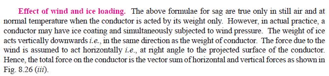
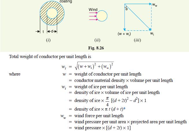
25 5.) the non uniform distribution of current in the cross section 6.) the increase of resistance 18. What is ACSR conductor? ACSR conductor is an aluminum conductor with a steel core reinforced. It consists of central core of galvanized steel strand surrounded by a number of aluminum strands. ACSR is a composite conductor which combines the lightness, electrical conductivity and rustle ness of aluminum with the high tensil strength and has a larger diameter. So to minimize the conona losses they are now used as overhead conductors in the long distance transmission lines. 19. What is a composite conductor? A conductor which operates at high voltages and composes of two or more elements or strands, electrically in parallel is called as a composite conductor. 20. What is bundle conductor? A bundle conductor is a conductor made up of two or more sub conductors and is used as one phase conductors. 21. What are the advantages of using bundled conductors? The advantages of using bundled conductors are 7.) reduced reactance 8.) reduced voltage gradient 9.) reduced corona loss 10.) reduced radio interference 11.) reduced surge impedance 22. Define symmetrical spacing. In 3 phase system when the line conductors are equidistant from each other then it is called symmetrical spacing. 23. Mention the sources of audible noise generation in EHV transmission systems? Corona Humming of transformers Cooking Systems Mechanical and Electrical auxiliaries 24. What is the need of transposition? (Nov 2011) When three phase line conductors have unsymmetrical spacing the flux linkages and inductances of each phase are not the same. This results in the unequal voltage drops in the three phases even if the currents in the conductors are balanced. Therefore the voltage at the receiving end will not be the same for all phases. To avoid the unbalancing effect the positions of the line conductors are interchanged at regular intervals along the line so that each conductor occupies the original position of every other conductor over an equal distance. This exchanging of positions of conductors is called transposition. Department of EEE Page 25
 The potential difference between conductors, at which the electric field intensity at the surface of the conductor exceeds the critical value and corona occurs is known as critical")
 An alternating current when flowing through the conductor, does not distribute uniformly, rather it has the tendency to concentrate near the surface of the conductor.")
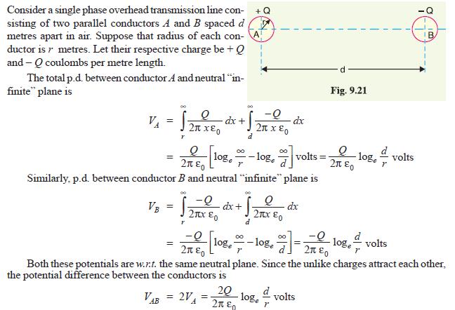
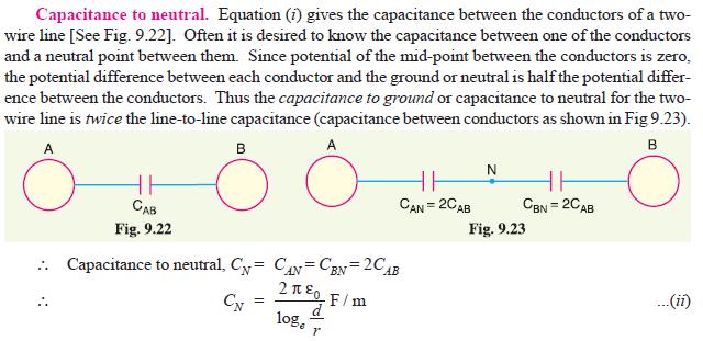
26 25. Define the term critical disruptive voltage? (Nov 2011) The potential difference between conductors, at which the electric field intensity at the surface of the conductor exceeds the critical value and corona occurs is known as critical disruptive voltage. 26. What is skin effect? Is it applicable to DC current also? (Nov 2012) An alternating current when flowing through the conductor, does not distribute uniformly, rather it has the tendency to concentrate near the surface of the conductor. This phenomenon is called skin effect.it is not applicable to DC current. 27. Write the expression for a capacitance of a single-phase transmission line. (Nov 2012) 0 Capacitance per unit length between the conductors C AB F / m D ln r 2 0 Capacitance between line and neutral conductors C AN F / m D ln r PART B 1. Derive an expression for the capacitance of a 3-phase line with equilateral spacing Department of EEE Page 26

27 2. Derive the capacitance of single phase two wire line taking earth s effect into account. Department of EEE Page 27

28 Department of EEE Page 28

29 3. Derive from first principles, the capacitance of a single phase overhead line. Department of EEE Page 29
30 Department of EEE Page 30


31 4. Derive the expression for the inductance of each line when the conductors are unsymmetrical placed. Department of EEE Page 31

32 Department of EEE Page 32


33 5. Derive an expression to find the loop inductance of single phase overhead transmission line. Department of EEE Page 33
34 Department of EEE Page 34


35 6. Explain in detail the theory of corona formation. Give its advantages and disadvantages. And the expression of power loss. (Nov 2012) Department of EEE Page 35


36 7. Derive from the fundamentals, an expression for critical disruptive voltage. Department of EEE Page 36
")

37 8. Write short notes on the following: (i) STATCOM (ii) UPFC Department of EEE Page 37
38 Department of EEE Page 38

 Department")
39 9. Explain the various factors affecting the corona loss. (Nov 2011) Department of EEE Page 39
40 10. Find the inductance per phase per km of double circuit 3 phase line shown in fig. The line is completely transposed and operated at a frequency of 50 Hz. r =6mm. (Nov 2011) A 5m C 3m B 6 m B 3m C 5m A Solution: 7. Derive an expression for capacitance of 3-phase un symmetrically spaced transmission line. (Nov 2012) 8. Explain the following with respect to corona (i) Corona (ii) effect (iii) disruptive critical voltage (iv)visual critical voltage (v) corona power loss (Nov2012) ' r D (i) Corona effect (4) The Phenomenon of violet glow; hissing noise and production of ozone gas in an over head transmission line is known as corona effect mm 3 s s1 s2 s3 4 s1 aa aa ' a ' a ' a ' a s3 s D D D D D D D D D D m 3 3 Dm DABDBC DCA m Dm Inductance per phase= mh / km Ds 9. Find the inductance per Km of a three phase three wire transmission system consisting of 2 cm diameter conductors spaced 4 m apart in horizontal plane. The conductors are regularly transposed. (May 2012) Department of EEE Page 40
 Capacitance of the line = =0.")
41 Inductance /phase/km 5.03m = 12.9X10⁻³ H 10. Find the capacitance between the conductors of a single phase 10 Km long line. The diameter of each conductor is cm. The spacing between the conductor is 1.25 m. (May 2012) Capacitance of the line = =0.5217X10⁻¹¹ F UNIT III MODELLING AND PERFORMANCE OF TRANSMISSION LINES Department of EEE Page 41
42 PART A 1. Give the lengthwise classification of transmission lines. Transmission lines are classified as 1.) short transmission lines (length <80 km) 2.) medium transmission lines (80km<length < 250km) 3.) long transmission lines (length > 250 km) 2. Define regulation of a transmission line. (Nov 2012) Regulation of a transmission line is defined as the change in voltage at the receiving end when full load is thrown off the sending end voltage remaining the same. It is usually expressed as a percentage of receiving end voltage % regulation ' VR V V R R 100 ' Where V R - no load voltage at the receiving end V R - receiving end voltage 3. Define efficiency of a transmission line. Efficiency of a transmission line is defined as the ratio of power received to the power sent. Power delivered Power sent out VRI RCos R V I Cos s s s Where V R, I R, Cos R are the receiving end voltage, current and power factor respectively. V s, I s, Cos s are the sending end voltage, current and power factor respectively. 4. Explain the influence of power factor on the regulation of a transmission line. 1.) when the load PF ( cos R ) is lagging or unity or leading that IR cos R > IX L sin R then voltage regulation is positive (receiving end voltage is lesser than the sending end voltage) and increases with the decrease in power factor for lagging loads (for a given V R and I. 2.) when the load PF is leading to this extent that IR cos R < IX L sin R the voltage regulation is negative and decreases with the decrease in PF for leading loads (for a given V R and I) Department of EEE Page 42
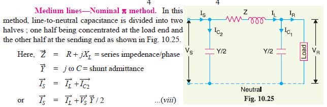
43 5. Under what circumstances, the receiving end voltage may be higher than that of the sending end? When load PF cos R is leading, IX L sin R >IR cos R then regulation is negative (i.e.). the receiving end voltage may be higher than that of the sending end. Where I load current X L -loop reactance cos R - receiving end power factor(leading) 6. Explain how capacitance effects are taken into account in medium transmission lines. Medium transmission lines have sufficient length (80-250km) and operate at voltages greater than 20kv. In such lines the capacitive current is appreciable and hence cannot be neglected. So to obtain reasonable accuracy the effects of capacitance must be taken into account. 7. What are the methods that are used for obtaining the performance calculations of medium lines? The methods that are used for obtaining the performance calculation of medium lines are 1.) end condenser method 2.) nominal T method 3.) nominal method 8. What is the difference between nominal T and nominal configuration? S.NO Nominal T Nominal 1.) In this the whole line capacitance is assumed to be concentrated at the middle point of the line and half the line resistance and reactance are lumped on its either side the receiving end. 2.) Full charging current flows over half the line In this the whole line capacitance is assumed to be divided into two halves, one half being connected at the receiving end and other half at Capacitance at the receiving end has no effect on the line drop. But the charging current of the second half capacitance is added to obtain the total sending current 3.) T-equivalent circuit -equivalent circuit 9. What are the limitations of nominal T and methods in transmission lines problems? Department of EEE Page 43
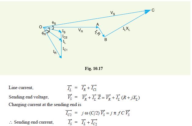
44 Generally the capacitance is uniformly distributed over the entire length of the line. But for easy calculations in nominal T and the capacitance is concentrated at one or two points also in nominal method the capacitance connected in the load side has no effect on voltage drop. Due to all these there may be considerable error in calculation. 10. How the capacitance effects are taken into account in a long transmission line? Long transmission lines have sufficient length and operate at voltage higher than 100kv the effects of capacitance cannot be neglected. Therefore in order to obtain reasonable accuracy in long transmission lines calculations, the capacitance effects must be taken into account. 11. What is surge impedance? The square root of the ration of line impedance (Z) and shunt admittance(y) is called the surge impedance (Z) of the line. 12. Define surge impedance loading or natural power of the line? Surge impedance loading is defined as the load of unity PF that can be delivered by the line of negligible resistance. 2 VRL PSIL Z Where o 2 VRL -line voltage at the receiving end Zo-surge impedance in ohms P SIL -surge impedance loading. 13. What are the ABCD constants? ABCD constants are generalized circuit constants of a transmission line. They are usually complex numbers. Input voltage and current are expressed in terms of output voltage and current. The constants A and D are dimensionless B and C are ohms and mhos respectively. 14. What is a power circle diagram? A power circle diagram is a diagram drawn for the transmission line network involving the generalized circuit constants and the sending end voltage V s and receiving end voltage V R. 15. What is the use of power circle diagram? Power circle diagram is used to determine the maximum power that can be transmitted over the line both at the receiving end and sending end. 16. Define attenuation in a transmission lines? Attenuation is defined as the power loss in line. It is nothing but the transmission loss (i.e.). the difference between the sending end power and receiving end power. Department of EEE Page 44
45 17. What is steady state stability limit? Steady state stability limit is the maximum flow of power through a particular point of power system without loss of stability when the power is increased very gradually. 18. Define critical disruptive voltage. It is the minimum phase to neutral voltage at which corona occurs 19. Define visual critical voltages Visual critical voltage is defined as the min. phase neutral voltage at which corona glow appears all along the line conductors 20. Write an expression for the power loss due to corona. f 25 r P V V 2 c X 10-5 KW/km/ph d where f - supply frequency Hz V phase to neutral r.m.s voltage in kv Vc critical disruptive voltage (r.m.s) per phase 21. What are the units for A,B,C and D in the ABCD parameters? A and D are dimensionless B and C are ohms and mhos respectively. 22. What are the voltages regulating equipments used in transmission system? Synchronous motors, tap changing transformers, series shut capacitors, booster transformers, compound generators, induction regulator. 23. Differentiate between voltage stability and rotor angle stability. Voltage stability: -It means load stability. -It is mainly related to reactive power transfer. -Here problems arise mainly in the event of faults. Rotor angle stability: -It means basically generator stability. -It is mainly interlinked to real power transfer. -Here problems arise during and after faults. 24. What are the methods used for voltage control of lines? The methods used for voltage control of lines are by using over compound generator Department of EEE Page 45
46 by excitation control by use of tap changing transformers auto-transformer tap changing booster transformer induction regulator and by improvement of power factor. 25. What is Ferranti effect? (Nov 2011) The phenomenon of rise in voltage at the receiving end of the lightly loaded or unloaded line is called as Ferranti s effect. 26. Distinguish between attenuation and phase constant. (Nov 2011) In long transmission line, Z Characteristics impedance Z c Y Propagation constant Attenuation constant Phase constant ZY j PART B 1. Deduce the expression for (a) %regulation (b) ABCD parameters of a short transmission line. Department of EEE Page 46
47 Department of EEE Page 47

48 Department of EEE Page 48


49 2. Two transmission line with generalized constants A 1 B 1 C 1 D 1 and A 2 B 2 C 2 D 2 are in parallel. Obtain the overall constants. Department of EEE Page 49

50 Department of EEE Page 50
51 3. Two transmission line with generalized constants A 1 B 1 C 1 D 1 and A 2 B 2 C 2 D 2 are in series. Obtain the overall constants. Department of EEE Page 51

52 4. Deduce the expression for (a) %regulation (b) ABCD parameters of a medium transmission line represented in nominal configuration. Department of EEE Page 52
53 Department of EEE Page 53

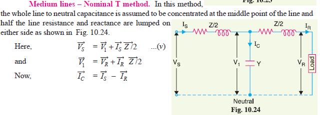
54 5. Deduce the expression for (a) %regulation (b) ABCD parameters of a medium transmission line represented in nominal T configuration. Department of EEE Page 54
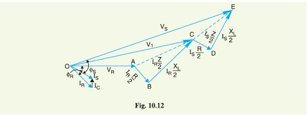
55 Department of EEE Page 55
56 6. A balanced 3-phase load of 30MW is supplied at 132kV, 50Hz and 0.85pf. lagging by means of a transmission line. The series impedance of a single conductor is (20+j52) ohms and the total phase-neutral admittance is 315X10-6 siemen. Using nominal T method, determine i) the A, B, C and D constants of the line (ii) sending end voltage (iii) regulation of the line.. Department of EEE Page 56

57 Department of EEE Page 57
58 7. A132kV, 50Hz, 3-phase transmission line delivers a load of 50MW at 0.8p.f. lagging at the receiving end. The generalized constants of the transmission line are: A=D= deg ; B=96 78deg; C= deg.Find the regulation of the line and charging current. Use nominal T method. 8. A 3 phase, 50 Hz, 150 km line has a resistance, inductive reactance and capacitive shunt admittance of 0.1 ohm and 3 x 10⁻⁶ S per km per phase. If the line delivers 50 MW at 110 KV and 0.8 pf lagging, determine the sending end voltage and current. Assume a nominal π circuit for the line. Department of EEE Page 58

59 Department of EEE Page 59
60 9. A balanced 3 phase load of 30 MW is supplied at 132 KV, 50 Hz and 0.85 pf lagging by means of transmission line. The series impedance of a single conductor is 20 +j 52 ohms and the total phase neutral admittance is 315 x 10-6 mho. Using nominal T method. Determine (a) The A,B, C and D constants of the line. (b) sending end voltage (c) Regulation of the line. (Nov 2011) zy o ( i) A D zy 0 B z (ii) V C Y s I 131 j81.62 R V j5413 s AV V 143 kv ; V 82.6kV s( line) s(ph) R BI R 0 Vs iii percentage regulation= VR / VR X % A 10. A 3 phase line having an impedance of 5 + j20 ohms per phase delivers a load of 30 MW at a power factor of 0.8 lag and voltage of 33 KV. Determine the capacity of the phase modifier to be installed at the receiving end if the voltage at the sending end is to be maintained at 33 KV. Assume the shunt admittance is neglected. (Nov 2012) 0 Z R jx 5 j Assume Y=0 (neglected) 1 A= YZ B Z V 33/ kV V r( ph) VV s r B AV 2 r B MM 17.61MW 17.61MW ' 15.2 MVA( perphase) 0 D s capacity of the phase modifier for 3phase= =45.6 MVA 11. A 15km long 3-phase overhead line delivers 5MW at 11kV at 0.8 lagging p.f line loss is 12% of power delivered. Line inductance is 1.1mH per km per phase. Find sending end voltage and voltage regulation. (Nov 2012) 12. (i) Perform the analysis of long transmission lines using RIGOROUS method. (ii) Explain the concept of surge impedance loading. (Nov 2012) Department of EEE Page 60
61 UNIT IV INSULATORS AND CABLES PART A 1. Where polythene cables are used? Non-hygroscopic used in cables for submarines and damp soil. Lighter used as aerial cables for vertical installations. 2. State the advantages of polythene insulators. Non-hygroscopic Light in weight Low dielectric constant Low loss factor and Low thermal resistance. 3. By what materials cable sheaths are made? Lead sheaths and Aluminium sheaths. 4. In what way Aluminium sheaths are superior to lead sheaths? Aluminium sheaths are smaller in weight, high mechanical strength, greater conductivity, cheap, easy to manufacture and install, withstand the required gas pressure without reinforcement. 5. Where corrugated seamless aluminium sheath is used in cables? Corrugated seamless aluminium (CSA) sheath is used in high voltage oil filled cables and telephone lines. 6. Why corrugated seamless aluminium sheath is used in cables? It is used because it is very flexible and easily by repeated bending the sheath is not distorted and it is not damaged. It has lesser weight and reduced thickness. 7. Why protective covering is done in cables? To protect the cables from mechanical damage, corrosion and electrolytic action when laid direct in the ground the protective covering is made. 8. By what material protective covering is made in cables? Bitumen &Bituminized materials PVC and Layers of fibrous materials. Department of EEE Page 61
62 9. What is meant by serving of a cable? Layers of fibrous material permitted with waterproof compound applied to the exterior of the cable is called serving of a cable. 10. Why armouring is done in the cables? To protect the sheath from mechanical damage. 11. Why armouring is not done in single core cables? The presence of magnetic material within the alternating magnetic field of a single core cable produces excessive losses. Hence single core cables are left unarmoured with non-magnetic materials like tin-bronze or silicon-bronze tapes or wires. 12. Why Aluminium is used as an armour material? It has non-magnetic properties, high conductivity and mechanical strength. 13. What is meant by grading of cables? The method of equalizing the stress in the dielectric of the cable is called the grading of cables. 14. Why the capacitance of the cable is very high than the capacitance of the overhead lines? The distances between the conductors are small. The distance between the cores and the earthed sheath is also small. The permittivity of the cable insulation is 3 to 5 times greater than that of air insulation. 15. Write the expression of the capacitance of a single core cable. C = (2πε 0 ε r ) / ln ( R/r ) F/m Where, R = Resistance of a conductor r = Radius of a conductor Department of EEE Page 62
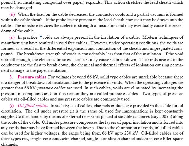
63 ε 0 = x F/m ε r = Relative permittivity of the cable insulation 16. What is meant by charging current of a cable? The capacitance of a cable determines the charging current. The charging current restricts the use of cables on EHV lines. The current carrying capacity of an a.c. cable is also reduced by the charging current. 17. Why power loss occurs in the dielectric of a cable? Due to conductivity of insulation Dielectric absorption. Ionization or corona 18. Mention the methods of laying the cables. Direct laying, draw in system and solid system 19. Mention the advantages of direct laying of cables. It is simple and cheaper method. It gives the best conditions for dissipating the heat generated in the cables. 20. State any two disadvantages of direct laying method. Localisation of fault is difficult. It cannot be used in congested areas where excavation is inconvenient. 21. Mention the disadvantages of pressure cables. The cost of the pressure tube is high. 22. Mention the types of gas pressure cables/ External and internal pressure cables. 23. What are the types of oil filled cables? Department of EEE Page 63
64 Single core conductor channel cables Sheath channel cables and 3 core filler space channel. 24. What are the types of pressure cables? Oil filled cables and Gas pressure cables. 25. What is the operating range of pressure cables? It is greater than 66 kv. 26. What are the advantages of separate lead screened (SL) cables over H- type cables? The possibility of core to core breakdown decreases to a large extent. Bending of cables becomes easy owing to no overall lead sheath. 27. Mention the disadvantages of oil filled cables. Expensive Laying and maintenance of cables is quite complicated. 28. What are the types of screened cables? H type and Separate Lead screened (SL) type cables. 29. Why the working voltage level of belted cables is limited to 22 kv? It is limited because beyond 22 kv tangential stresses acting along the layers of paper insulation set up large current. These current causes local heating resulting in the risk of breakdown insulation at any moment. 30. Up to what voltage range are belted cables used? Upto 11 kv. In some extra ordinary cases they are used upto even 22 kv. 31. What are the different types of cables that are generally used for 3 phase service? Department of EEE Page 64
65 Belted cable Screened cables and Pressure cables. 32. Why cables are not used for long distance transmission? Cables are not used for long distance transmissions due to their large charging currents. 33. Mention the 3 main parts of the cable? Conductor Dielectric Sheath 34. What is the function of conductor? Conductor provides the conducting path for the current. 35. What is the purpose of insulation in a cable? The insulation or dielectric withstands the service voltage and isolates the conductor with other objects. 36. What is the function of sheath in a cable? The sheath does not allow the moisture to enter and protects the cable from all external influences like chemical or electrochemical attack fire etc. 37. Mention the conductor materials in cables? Copper Aluminium 38. What is the purpose of stranding of conductors? Stranding increases the resistance of the cable.it has flexibility. 39. Define the segmental conductors. The stranded wires which are compacted by the rollers to minimize the air spaces between the individual wires are called segmented conductors.here the conductor size is reduced for a given conductance. 40.State the properties of insulating materials. It should have high insulation resistance, high dielectric strength, good Department of EEE Page 65
66 mechanical properties, non-hygroscopic, capable of being operated at high temperatures,low thermal resistance and low power factor. 41. Mention the commonly used power cables. Impregnated paper Polyvinyl chloride Polyethene 42. Mention the advantages of PVC over paper insulated cables. Reduced cost and weight Insulation is resistant to water Simplified jointing Increased flexibility. 43. State the merits of paper insulated cables. High current carrying capacity Long life and Greater reliability 44. What are the advantages of string insulators? (Nov 2011) (i) Number of units can be increased. (ii) Replacement of fault insulator unit is possible. (iii) Low tension due to its swinging 45. What are the methods of grading of cables? (Nov 2011) Capacitance grading and Inter sheath grading. PART B 1. With the neat diagram, show and explain the various parts of a oil filled cable. Department of EEE Page 66

67 Department of EEE Page 67
68 2. Derive the expression for the insulation resistance of a single core cable. Department of EEE Page 68
69 Department of EEE Page 69
70 3. Deduce an expression for capacitance C for a single core cable. Department of EEE Page 70
71 4. Discuss grading of underground cables Department of EEE Page 71

72 Department of EEE Page 72
73 Department of EEE Page 73
74 Department of EEE Page 74


75 5. Draw and explain pin and suspension type insulators. Department of EEE Page 75

76 6. A single core cable has a conductor diameter of 1 cm and insulation thickness of 0.4 cm. If the specific resistance of insulation is 5X10 14 ohm-cm. Calculate the insulation resistance for a 2 Km length of the cable. 7. In a 3 phase overhead system each line is suspended by a string of 3 insulators. The voltages across top unit and middle unit are 8Kv & 11Kv respectively. Calculate a) the ratio of capacitance between pin and earth to the self capacitance of the each unit. b) the line voltage c) string efficiency. Department of EEE Page 76
77 Department of EEE Page 77
78 8. A 3 phase overhead transmission line is being supported by three disc insulators. The potentials across top unit and middle unit are 9 KV and 11 KV respectively. Calculate (i) the ratio of capacitance between pin and earth to the self capacitance of each unit. (ii) the line voltage and (iii) string efficiency. (Nov 2011) Department of EEE Page 78

 Department of EEE")
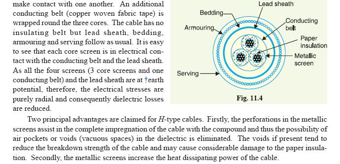
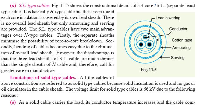
79 9. With neat diagrams explain constructional features of various types of cables. (Nov 2011) Department of EEE Page 79
80 Department of EEE Page 80

81 Department of EEE Page 81

82 11. The insulation resistance of the single core cable is 495 Mohms per Km. If the core diameter is 2.5 cm and the resistivity of insulation is 4.5 x ohm-cm. Find the insulation thickness. Department of EEE Page 82
83 UNIT V SUBSTATION, GROUNDING SYSTEM AND DISTRIBUTION SYSTEM PART A 1. What is a substation? The assembly of apparatus used to change some characteristic ( eg: voltage, A.C to D.C frequency power factor etc) of electric supply is called a substation. 2. Mention any two layouts of laying out a substation. Location should be at the center of the load Should provide safe and reliable arrangement. 3. How substations are classified? Service requirement Constructional feature. 4. State the various types of substation according to its service requirements. Transformer substation Switching substation Power factor correction substation Frequency changer substation Converting substation Industrial substation 5. List the types of substations classified according to its construction. Indoor substation Outdoor substation Pole mounted substation 6. Mention any two comparisons between indoor and outdoor substations. INDOOR: Space required and clearances between the conductors are less. Time required for erection and possibility of faults are more. OUTDOOR: Department of EEE Page 83
84 Space required and clearances between conductors are more. Time required for erection and possibility of faults are less. 7. List the various substation equipments. Transformer Busbars Insulators Isolators Circuit breaker Relays Lightning arresters. 8. Define step potential. It is the voltage between the feet of a person standing on the floor of the substation with 0.5m spacing between two feet during the flow of earth fault current through the earthing system. 9. Define touch potential. It is the voltage between the fingers of raised hand touching the faulted structure and the feet of the person standing on the substation floor. The person should not get shocked even if the earth structure is carrying faulted current.i.e touch potential should be very low. 10. Define sag of a line. The difference in level between the points of supports and the lowest point of the conductor is called as sag. 11. Mention the factors that affect sag in the transmission line. Weight of the conductor Length of the span Working tensile Strength and Temperature. 12. What is the reason for the sag in the transmission line? While erecting the line, if the conductors are stretched too much between supports then there prevails an excessive tension on the line which Department of EEE Page 84
85 may break the conductor. In order to have safe tension in the conductor a sag in the line is allowed. 13. What is power circle diagram? It is a diagram drawn for the transmission lines network involving the generalized circuit constants and the sending end and receiving end voltage. 14. What are the voltages regulating equipments used in transmission system? Synchronous motors Tap changing transformers Series and shunt capacitors Booster transformers Compound generators and Induction regulator. 15. Mention the methods used for voltage control of lines. Tap changing auto- transformer Booster transformer Excitation control and Induction regulator. 16. What is sending end power circle diagram? The circle drawn with sending end true and reactive power as the horizontal and vertical co-ordinates are called sending end power circle diagram. 17. What is receiving end power circle diagram? The circle drawn with receiving end values are called receiving end power circle diagram. 18. Mention two significance of neutral grounding The system voltage during the earth fault depends on neutral earthing. Protection against arcing grounds, unbalanced voltages with respect to earth, protection from lightning. 19. What is neutral grounding? Connecting the neutral or star point of any electrical equipment(generator,transformer etc) to earth. 20. Define coefficient of earthing. Department of EEE Page 85
86 It is defined as the ratio of highest rms voltage of healthy line to earth to line to line rms voltage. 21. Define resonant frequency It is defined as a reactance earthing with selected value of reactance to match with the line to ground capacitance. 22. Mention the disadvantages of ungrounded neutral Occurrence of insulation breakdown leading to the heavy phase to phase fault condition. Voltages due to lightning surges do not find path to earth. 23. Mention two advantages of neutral grounding. Arcing grounds are eliminated. The over voltages due to lightning and switching surges are discharged to ground. 24. Name the various types of grounding. Solid grounding Resistance grounding Reactance grounding Resonant grounding 25. Give the response of resistance for earth driven rods. R= ρ /2πl *ln(2l/d) Where, l = length of the rod d = diameter of the rod ρ = resistivity of the rod 26. For the uniformly current carrying ground driven rod, give the resistance value. R=ρ/(2πl) *(ln(8l/d)-1) Where ρ = Resistivity of the rod l = length of the rod d = diameter of the rod 27. Define screening coefficient. Screening coefficient for n electrodes in parallel is Department of EEE Page 86
 Using grid mats with several earth electrodes and using grounding resistance. 29. Define the terms feeders and service mains?")
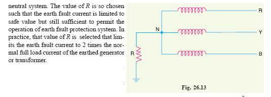
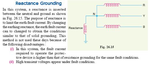
87 = (resistance of one electrode)/(resistance of n electrodes in parallel * n) 28.What are the various methods of earthing in substation? (Nov 2011) Using grid mats with several earth electrodes and using grounding resistance. 29. Define the terms feeders and service mains? (Nov 2011) Feeder is a conductor or transmission line which transmits current from the generating stations to different distributing substations. Conductors which connect consumer s premises with the distributor are called service mains. PART B 1. Explain in detail the methods of neutral grounding systems. Department of EEE Page 87

88 Department of EEE Page 88
89 Department of EEE Page 89
90 Department of EEE Page 90


91 27. Explain in detail the types of sub stations. Department of EEE Page 91

92 Department of EEE Page 92

93 Department of EEE Page 93
94 28. A 800 meters 2 wire dc distributor AB fed from both ends is uniformly loaded at the rate of 1.25 A/m run. Calculate the voltage at the feeding points A and B if the minimum potential of 220 V occurs at point C at a distance of 450 m from the end A. Resistance of each conductor is 0.05 ohm/km Department of EEE Page 94


95 29. A 2 wires dc distributor cable AB is 2 km long and supplies loads of 100 A, 150 A, 200 A and 50 A situated 500 m, 1000 m, 1600 m and 2000 m from the feeding point A. Each conductor has a resistance of 0.01 ohm per 1000 m. Calculate the potential difference at each load point if a potential difference of 300 V is maintained at point A. Department of EEE Page 95
96 30. A 2 wire dc distributor 200 m long is uniformly loaded with 2 A/m. Resistance of single wire is 0.3 ohm/km. If the distributor is fed at one end, calculate (i) the voltage drop upto a distance of 150 m from the feeding point. (ii) the maximum voltage drop. Department of EEE Page 96


97 31. Explain the classification of substation based on service requirement and constructional feature. Department of EEE Page 97


98 32. Exalin various equipments in transformer substation. Department of EEE Page 98

99 33. E x p l Department of EEE Page 99

100 ain ring distributor and ring main distributor with interconnector. Department of EEE Page 100
101 9. A 3 wire dc distributor is fed at one end at 220 V between wires and middle wire as shown in fig. The numbers between section indicate the resistance of the respective section. Calculate the voltage between middle wire and outer at each load point. (Nov 12) V 5 A 10 A 12 A V 15A 5 A A V AD = = 217.8V V AB =4.4 V V DH = -2.6 V V HE =0.4 V V BC = 24 V, V BF =2.4 V, V FL =0.3 V V CL =215.9 V V HI =203.7V V FJ =196.7 V V GK = V 10. Draw the circuit arrangement and explain the various elements of the following bus-bar arrangements. (Nov 2011) (i) Single bus scheme Department of EEE Page 101

102 Department of EEE Page 102

103 Department of EEE Page 103
Fatima Michael college of Engineering and Technology
 Fatima Michael college of Engineering and Technology DEPARTMENT OF ELECTRICAL AND ELECTRONICS ENGINEERING EE2303 TRANSMISSION AND DISTRIBUTION SEM: V Question bank UNIT I INTRODUCTION 1. What is the electric
CONTENTS. 1. Introduction Generating Stations 9 40
 CONTENTS 1. Introduction 1 8 Importance of Electrical Energy Generation of Electrical Energy Sources of Energy Comparison of Energy Sources Units of Energy Relationship among Energy Units Efficiency Calorific
Roll No. :... Invigilator s Signature :.. CS/B.TECH(EE)/SEM-5/EE-502/ POWER SYSTEM-I. Time Allotted : 3 Hours Full Marks : 70
/SEM-5/EE-502/ POWER SYSTEM-I. Time Allotted : 3 Hours Full Marks : 70") Name : Roll No. :.... Invigilator s Signature :.. CS/B.TECH(EE)/SEM-5/EE-502/2011-12 2011 POWER SYSTEM-I Time Allotted : 3 Hours Full Marks : 70 The figures in the margin indicate full marks. Candidates
Name : Roll No. :.... Invigilator s Signature :.. CS/B.TECH(EE)/SEM-5/EE-502/2011-12 2011 POWER SYSTEM-I Time Allotted : 3 Hours Full Marks : 70 The figures in the margin indicate full marks. Candidates
EE 740 Transmission Lines
 EE 740 Transmission Lines 1 High Voltage Power Lines (overhead) Common voltages in north America: 138, 230, 345, 500, 765 kv Bundled conductors are used in extra-high voltage lines Stranded instead of
EE 340 Transmission Lines
 EE 340 Transmission Lines Physical Characteristics Overhead lines An overhead transmission line usually consists of three conductors or bundles of conductors containing the three phases of the power system.
III/IV B.Tech (Regular/Supplementary) DEGREE EXAMINATION
 DEGREE EXAMINATION") Hall Ticket Number: 14EE503 October, 2018 Fifth Semester Time: Three Hours Answer Question No.1 compulsorily. Answer ONE question from each unit. III/IV B.Tech (Regular/Supplementary) DEGREE EXAMINATION
Hall Ticket Number: 14EE503 October, 2018 Fifth Semester Time: Three Hours Answer Question No.1 compulsorily. Answer ONE question from each unit. III/IV B.Tech (Regular/Supplementary) DEGREE EXAMINATION
EE 340 Transmission Lines. Spring 2012
 EE 340 Transmission Lines Spring 2012 Physical Characteristics Overhead lines An overhead transmission line usually consists of three conductors or bundles of conductors containing the three phases of
Electrical Power Systems
 Electrical Power Systems CONCEPT, THEORY AND PRACTICE SECOND EDITION SUBIR RAY Professor MVJ College of Engineering Bangalore PHI Learning Pfcte tofm Delhi-110092 2014 Preface xv Preface to the First Edition
EE 741. Primary & Secondary Distribution Systems
 EE 741 Primary & Secondary Distribution Systems Radial-Type Primary Feeder Most common, simplest and lowest cost Example of Overhead Primary Feeder Layout Example of Underground Primary Feeder Layout Radial-Type
EL 403 MODEL TEST PAPER - 1 POWER SYSTEMS. Time: Three Hours Maximum Marks: 100
 POWER SYSTEMS Time: Three Hours Maximum Marks: 0 Answer five questions, taking ANY TWO from Group A, any two from Group B and all from Group C. All parts of a question (a, b, etc. ) should be answered
Transmission Line Models Part 1
 Transmission Line Models Part 1 Unlike the electric machines studied so far, transmission lines are characterized by their distributed parameters: distributed resistance, inductance, and capacitance. The
ECE 422/522 Power System Operations & Planning/Power Systems Analysis II 5 - Reactive Power and Voltage Control
 ECE 422/522 Power System Operations & Planning/Power Systems Analysis II 5 - Reactive Power and Voltage Control Spring 2014 Instructor: Kai Sun 1 References Saadat s Chapters 12.6 ~12.7 Kundur s Sections
Determination of Optimal Account and Location of Series Compensation and SVS for an AC Transmission System
 ISSN (e): 2250 3005 Vol, 04 Issue, 5 May 2014 International Journal of Computational Engineering Research (IJCER) Determination of Optimal Account and Location of Series Compensation and SVS for an AC
Design and Simulation of Passive Filter
 Chapter 3 Design and Simulation of Passive Filter 3.1 Introduction Passive LC filters are conventionally used to suppress the harmonic distortion in power system. In general they consist of various shunt
DEPARTMENT OF ELECTRICAL AND ELECTRONICS ENGINEERING QUESTION BANK SUBJECT CODE & NAME : EE 1402 HIGH VOLTAGE ENGINEERING UNIT I
 DEPARTMENT OF ELECTRICAL AND ELECTRONICS ENGINEERING QUESTION BANK SUBJECT CODE & NAME : EE 1402 HIGH VOLTAGE ENGINEERING YEAR / SEM : IV / VII UNIT I OVER VOLTAGES IN ELECTRICAL POWER SYSTEMS 1. What
BE Semester- VI (Electrical Engineering) Question Bank (E 605 ELECTRICAL POWER SYSTEM - II) Y - Y transformer : 300 MVA, 33Y / 220Y kv, X = 15 %
 Question Bank (E 605 ELECTRICAL POWER SYSTEM - II) Y - Y transformer : 300 MVA, 33Y / 220Y kv, X = 15 %") BE Semester- V (Electrical Engineering) Question Bank (E 605 ELECTRCAL POWER SYSTEM - ) All questions carry equal marks (10 marks) Q.1 Explain per unit system in context with three-phase power system and
BE Semester- V (Electrical Engineering) Question Bank (E 605 ELECTRCAL POWER SYSTEM - ) All questions carry equal marks (10 marks) Q.1 Explain per unit system in context with three-phase power system and
High Voltage DC Transmission Prof. Dr. S. N. Singh Department of Electrical Engineering Indian Institute of Technology, Kanpur
 High Voltage DC Transmission Prof. Dr. S. N. Singh Department of Electrical Engineering Indian Institute of Technology, Kanpur Module No. # 01 Lecture No. # 02 Comparison of HVAC and HVDC Systems Welcome
PRELIMINARIES. Generators and loads are connected together through transmission lines transporting electric power from one place to another.
 TRANSMISSION LINES PRELIMINARIES Generators and loads are connected together through transmission lines transporting electric power from one place to another. Transmission line must, therefore, take power
ELEC Transmission i and
 ELEC-1104 Lecture 5: Transmission i and Distribution ib ti Power System Layout Transmission and Distribution The transmission system is to transmit a large amount of energy from the power stations s to
1. What are the transmission system voltages used in India? 33kV, 66 kv For medium high voltage
 UNIT I POWER GENERATION Structure of electric power system; Sources of Electric Energy; Load Characteristics and Economic Aspects; Power Plants: Steam, Hydroelectric, Nuclear, Gas, Wind and Solar(Qualitative
3. (a) List out the advantages and disadvantages of HRC fuse (b) Explain fuse Characteristics in detail. [8+8]
![3. (a) List out the advantages and disadvantages of HRC fuse (b) Explain fuse Characteristics in detail. [8+8]](/thumbs/77/76027701.jpg "3. (a) List out the advantages and disadvantages of HRC fuse (b) Explain fuse Characteristics in detail. [8+8]") Code No: RR320205 Set No. 1 1. (a) Explain about Bewley s Lattice diagrams and also mention the uses of these diagrams. [6+2] (b) A line of surge impedance of 400 ohms is charged from a battery of constant
Code No: RR320205 Set No. 1 1. (a) Explain about Bewley s Lattice diagrams and also mention the uses of these diagrams. [6+2] (b) A line of surge impedance of 400 ohms is charged from a battery of constant
Case Study 1. Power System Planning and Design: Power Plant, Transmission Lines, and Substations
 Case Study 1 Power System Planning and Design: Power Plant, Transmission Lines, and Substations Lindsay Thompson, 5203120 Presented to Riadh Habash ELG 4125 11/10/2013 1.0 ABSTRACT A power plant delivers
Should we transform our lines to HVDC?
 Should we transform our lines to HVDC? HVDC versushvac Gaurav Dabhi 1, Nishit Sanghvi 2, Pinkesh Patel 3 1 Electrical Eng., G.H. Patel college of Eng. & Tech., dabhi60@gmail.com 2 Electrical Eng., G.H.
EH2741 Communication and Control in Electric Power Systems Lecture 2
 KTH ROYAL INSTITUTE OF TECHNOLOGY EH2741 Communication and Control in Electric Power Systems Lecture 2 Lars Nordström larsno@kth.se Course map Outline Transmission Grids vs Distribution grids Primary Equipment
SRI VIDYA COLLEGE OF ENGG AND TECH
 EEE6603 PSOC Page 1 UNIT-III REACTIVE POWER VOLTAGE CONTROL 1. List the various components of AVR loop? The components of automatic voltage regulator loop are exciter, comparator, amplifier, rectifier
Level 6 Graduate Diploma in Engineering Electrical Energy Systems
 9210-114 Level 6 Graduate Diploma in Engineering Electrical Energy Systems Sample Paper You should have the following for this examination one answer book non-programmable calculator pen, pencil, ruler,
Numbering System for Protective Devices, Control and Indication Devices for Power Systems
 Appendix C Numbering System for Protective Devices, Control and Indication Devices for Power Systems C.1 APPLICATION OF PROTECTIVE RELAYS, CONTROL AND ALARM DEVICES FOR POWER SYSTEM CIRCUITS The requirements
Cork Institute of Technology. Autumn 2008 Electrical Energy Systems (Time: 3 Hours)
") Cork Institute of Technology Bachelor of Science (Honours) in Electrical Power Systems - Award Instructions Answer FIVE questions. (EELPS_8_Y4) Autumn 2008 Electrical Energy Systems (Time: 3 Hours) Examiners:
Cork Institute of Technology Bachelor of Science (Honours) in Electrical Power Systems - Award Instructions Answer FIVE questions. (EELPS_8_Y4) Autumn 2008 Electrical Energy Systems (Time: 3 Hours) Examiners:
Busbars and lines are important elements
 CHAPTER CHAPTER 23 Protection of Busbars and Lines 23.1 Busbar Protection 23.2 Protection of Lines 23.3 Time-Graded Overcurrent Protection 23.4 Differential Pilot-Wire Protection 23.5 Distance Protection
Chapter Seven. Under Ground Cables
 Chapter Seven Under Ground Cables Construction of cables In the fig (7.1)below, shows the general construction of (3-condctor) cable The various part of cable are : 1- Core or conductor A cable may have
ROEVER ENGINEERING COLLEGE ELAMBALUR, PERAMBALUR DEPARTMENT OF ELECTRICAL & ELECTRONICS ENGINEERING
 ROEVER ENGINEERING COLLEGE ELAMBALUR, PERAMBALUR 621 212 DEPARTMENT OF ELECTRICAL & ELECTRONICS ENGINEERING EE1003 HIGH VOLTAGE ENGINEERING QUESTION BANK UNIT-I OVER VOLTAGES IN ELECTRICAL POWER SYSTEM
Unit 3 Magnetism...21 Introduction The Natural Magnet Magnetic Polarities Magnetic Compass...21
 Chapter 1 Electrical Fundamentals Unit 1 Matter...3 Introduction...3 1.1 Matter...3 1.2 Atomic Theory...3 1.3 Law of Electrical Charges...4 1.4 Law of Atomic Charges...4 Negative Atomic Charge...4 Positive
HIGH VOLTAGE ENGINEERING(FEEE6402) LECTURER-24
 LECTURER-24") LECTURER-24 GENERATION OF HIGH ALTERNATING VOLTAGES When test voltage requirements are less than about 300kV, a single transformer can be used for test purposes. The impedance of the transformer should
LECTURER-24 GENERATION OF HIGH ALTERNATING VOLTAGES When test voltage requirements are less than about 300kV, a single transformer can be used for test purposes. The impedance of the transformer should
Preface...x Chapter 1 Electrical Fundamentals
 Preface...x Chapter 1 Electrical Fundamentals Unit 1 Matter...3 Introduction...3 1.1 Matter...3 1.2 Atomic Theory...3 1.3 Law of Electrical Charges...4 1.4 Law of Atomic Charges...5 Negative Atomic Charge...5
KNOW MORE ABOUT THE TRANSFORMERS. Glossary Transformers
 KNOW MORE ABOUT THE TRANSFORMERS Glossary Transformers Ambient temperature The existing temperature of the atmosphere surrounding a transformer installation. Ampere The practical unit of electric current.
Coil Products Beginnings 1960 State of the Art. Customer partnership around the globe. Continuous innovation since 1900
 Coil Products Coil Products Customer partnership around the globe More than 250,000 coil products delivered to more than 170 countries. More than 60 years of operational experience. 35,000 in Europe 13,000
ELEMENTS OF FACTS CONTROLLERS
 1 ELEMENTS OF FACTS CONTROLLERS Rajiv K. Varma Associate Professor Hydro One Chair in Power Systems Engineering University of Western Ontario London, ON, CANADA rkvarma@uwo.ca POWER SYSTEMS - Where are
Transmission of Electrical Energy
 Transmission of Electrical Energy Electrical energy is carries by conductors such as overhead transmission lines and underground cables. The conductors are usually aluminum cable steel reinforced (ACSR),
ELECTROMAGNETIC INDUCTION AND ALTERNATING CURRENT (Assignment)
") ELECTROMAGNETIC INDUCTION AND ALTERNATING CURRENT (Assignment) 1. In an A.C. circuit A ; the current leads the voltage by 30 0 and in circuit B, the current lags behind the voltage by 30 0. What is the
ELECTROMAGNETIC INDUCTION AND ALTERNATING CURRENT (Assignment) 1. In an A.C. circuit A ; the current leads the voltage by 30 0 and in circuit B, the current lags behind the voltage by 30 0. What is the
High Voltage DC Transmission 2
 High Voltage DC Transmission 2 1.0 Introduction Interconnecting HVDC within an AC system requires conversion from AC to DC and inversion from DC to AC. We refer to the circuits which provide conversion
PROTECTION APPLICATION HANDBOOK
 BOOK No 6 Revision 0 Global Organization Innovative Solutions Product & Substation System Business Business PROTECTION APPLICATION HANDBOOK BA THS / BU Transmission Systems and Substations LEC Support
Embedded Generation Connection Application Form
 Embedded Generation Connection Application Form This Application Form provides information required for an initial assessment of the Embedded Generation project. All applicable sections must be completed
Single Line Diagram of Substations
 Single Line Diagram of Substations Substations Electric power is produced at the power generating stations, which are generally located far away from the load centers. High voltage transmission lines are
Conventional Paper-II-2011 Part-1A
 Conventional Paper-II-2011 Part-1A 1(a) (b) (c) (d) (e) (f) (g) (h) The purpose of providing dummy coils in the armature of a DC machine is to: (A) Increase voltage induced (B) Decrease the armature resistance
Aligarh College of Engineering & Technology (College Code: 109) Affiliated to UPTU, Approved by AICTE Electrical Engg.
 Affiliated to UPTU, Approved by AICTE Electrical Engg.") Aligarh College of Engineering & Technology (College Code: 19) Electrical Engg. (EE-11/21) Unit-I DC Network Theory 1. Distinguish the following terms: (a) Active and passive elements (b) Linearity and
Aligarh College of Engineering & Technology (College Code: 19) Electrical Engg. (EE-11/21) Unit-I DC Network Theory 1. Distinguish the following terms: (a) Active and passive elements (b) Linearity and
ENGINEERING ACADEMY X V
 1. Two incandescent bulbs of rating 230, 100 W and 230, 500 W are connected in parallel across the mains. As a result, what will happen? a) 100 W bulb will glow brighter b) 500 W bulb will glow brighter
1 Introduction General Background The New Computer Environment Transmission System Developments Theoretical Models and Computer Programs
 Modeling Techniques in Power Systems 1 General Background The New Computer Environment Transmission System Developments Theoretical Models and Computer Programs 2 Transmission Systems Linear Transformation
R10. III B.Tech. II Semester Supplementary Examinations, January POWER SYSTEM ANALYSIS (Electrical and Electronics Engineering) Time: 3 Hours
 Time: 3 Hours") Code No: R3 R1 Set No: 1 III B.Tech. II Semester Supplementary Examinations, January -14 POWER SYSTEM ANALYSIS (Electrical and Electronics Engineering) Time: 3 Hours Max Marks: 75 Answer any FIVE Questions
Code No: R3 R1 Set No: 1 III B.Tech. II Semester Supplementary Examinations, January -14 POWER SYSTEM ANALYSIS (Electrical and Electronics Engineering) Time: 3 Hours Max Marks: 75 Answer any FIVE Questions
Generation of Sub-nanosecond Pulses
 Chapter - 6 Generation of Sub-nanosecond Pulses 6.1 Introduction principle of peaking circuit In certain applications like high power microwaves (HPM), pulsed laser drivers, etc., very fast rise times
Transmission Line Transient Overvoltages (Travelling Waves on Power Systems)
") Transmission Line Transient Overvoltages (Travelling Waves on Power Systems) The establishment of a potential difference between the conductors of an overhead transmission line is accompanied by the production
Transmission Line Transient Overvoltages (Travelling Waves on Power Systems) The establishment of a potential difference between the conductors of an overhead transmission line is accompanied by the production
COURSE PLANNER SUBJECT: ELECTRICAL POWER SYSTEM II
 COURSE PLANNER SUBJECT: ELECTRICAL POWER SYSTEM II [260908] B.E. Third Year Class Electrical 204 Term: 6/2 (DEC-6 to APR-7) Faculty: PROF. J. I. JARIWALA PROF. A. S. SHAH PROF. T. M. PANCHAL PROF. N. B.
Overview of Actuation Thrust
 Overview of Actuation Thrust Fred Wang Thrust Leader, UTK Professor ECE 620 CURENT Course September 13, 2017 Actuation in CURENT Wide Area Control of Power Power Grid Grid Measurement &Monitoring HVDC
University of Rajshahi Department of Electrical & Electronic Engineering B.Sc. Engineering Part-IV Odd Semester Examination- 2017
 Course Code: EEE 4141 Course Title: Power System i. Answer to all parts (a), (b), (c) etc. of a question must be contiguous. ii. Use separate answer script for each Section (A/B). iii. Right margin indicates
IV B. Tech. II Sem (13EE432A) ELECTRICAL DISTRIBUTION SYSTEMS. (Elective - II)
 ELECTRICAL DISTRIBUTION SYSTEMS. (Elective - II)") COURSE OBJECTIVES: Students will be able to (13EE432A) ELECTRICAL DISTRIBUTION SYSTEMS (Elective - II) 1. Memorize modelling of loads and their characteristics 2. Understand design of substations 3. Compare
COURSE OBJECTIVES: Students will be able to (13EE432A) ELECTRICAL DISTRIBUTION SYSTEMS (Elective - II) 1. Memorize modelling of loads and their characteristics 2. Understand design of substations 3. Compare
Conventional Paper-II-2013
 1. All parts carry equal marks Conventional Paper-II-013 (a) (d) A 0V DC shunt motor takes 0A at full load running at 500 rpm. The armature resistance is 0.4Ω and shunt field resistance of 176Ω. The machine
FGJTCFWP"KPUVKVWVG"QH"VGEJPQNQI[" FGRCTVOGPV"QH"GNGEVTKECN"GPIKPGGTKPI" VGG"246"JKIJ"XQNVCIG"GPIKPGGTKPI
 FGJTFWP"KPUKWG"QH"GEJPQNQI[" FGRTOGP"QH"GNGETKEN"GPIKPGGTKPI" GG"46"JKIJ"XQNIG"GPIKPGGTKPI Resonant Transformers: The fig. (b) shows the equivalent circuit of a high voltage testing transformer (shown
Overview of Actuation Thrust
 Overview of Actuation Thrust Fred Wang Thrust Leader, UTK Professor Prepared for CURENT Course September 4, 2013 Actuation in CURENT Wide Area Control of Power Power Grid Grid Measurement &Monitoring HVDC
3. What is hysteresis loss? Also mention a method to minimize the loss. (N-11, N-12)
") DHANALAKSHMI COLLEGE OF ENGINEERING, CHENNAI DEPARTMENT OF ELECTRICAL AND ELECTRONICS ENGINEERING EE 6401 ELECTRICAL MACHINES I UNIT I : MAGNETIC CIRCUITS AND MAGNETIC MATERIALS Part A (2 Marks) 1. List
DHANALAKSHMI COLLEGE OF ENGINEERING, CHENNAI DEPARTMENT OF ELECTRICAL AND ELECTRONICS ENGINEERING EE 6401 ELECTRICAL MACHINES I UNIT I : MAGNETIC CIRCUITS AND MAGNETIC MATERIALS Part A (2 Marks) 1. List
High Voltage DC Transmission Prof. Dr. S. N. Singh Department of Electrical Engineering Indian Institute of Technology Kanpur
 High Voltage DC Transmission Prof. Dr. S. N. Singh Department of Electrical Engineering Indian Institute of Technology Kanpur Module No. # 01 Lecture No. # 03 So, in last two lectures, we saw the advantage
Chapter -3 ANALYSIS OF HVDC SYSTEM MODEL. Basically the HVDC transmission consists in the basic case of two
 Chapter -3 ANALYSIS OF HVDC SYSTEM MODEL Basically the HVDC transmission consists in the basic case of two convertor stations which are connected to each other by a transmission link consisting of an overhead
Power Quality enhancement of a distribution line with DSTATCOM
 ower Quality enhancement of a distribution line with DSTATCOM Divya arashar 1 Department of Electrical Engineering BSACET Mathura INDIA Aseem Chandel 2 SMIEEE,Deepak arashar 3 Department of Electrical
Unit 2. Single Line Diagram of Substations
 Unit 2 Single Line Diagram of Substations Substations Electric power is produced at the power generating stations, which are generally located far away from the load centers. High voltage transmission
Improving Power Transfer Capability of EHV AC Double circuit Transmission line by Enhancing Surge Impedance Loading level
 Improving Power Transfer Capability of EHV AC Double circuit Transmission line by Enhancing Surge Impedance Loading level Varun Patel 1, J G Jamnani 2 1,2 School of Technology, Pandit Deendayal Petroleum
Insulation Co-ordination For HVDC Station
 Insulation Co-ordination For HVDC Station Insulation Co-ordination Definitions As per IEC 60071 Insulation Coordination is defined as selection of dielectric strength of equipment in relation to the operating
UProtection Requirements. Ufor a Large scale Wind Park. Shyam Musunuri Siemens Energy
 UProtection Requirements Ufor a Large scale Wind Park Shyam Musunuri Siemens Energy Abstract: In the past wind power plants typically had a small power rating when compared to the strength of the connected
A Study on Electrical Design Considerations of Power Transmission Lines
 A Study on Electrical Design Considerations of Power Transmission Lines Gaddam Siva Ph.D Scholar, Department of Electrical Engineering, SSSUTMS, Sehore, Madhya Pradesh, India ABSTRACT: The power is generated
PRUDENT PRACTICES TO IMPROVE POWER FACTOR AND REDUCE POWER LOSS.
 1 PRUDENT PRACTICES TO IMPROVE POWER FACTOR AND REDUCE POWER LOSS. DEFINATIONS Working /Active Power: Normally measured in kilowatts (kw). It does the "work" for the system--providing the motion, torque,
Generator Advanced Concepts
 Generator Advanced Concepts Common Topics, The Practical Side Machine Output Voltage Equation Pitch Harmonics Circulating Currents when Paralleling Reactances and Time Constants Three Generator Curves
Interline Power Flow Controller: Review Paper
 Vol. (0) No. 3, pp. 550-554 ISSN 078-365 Interline Power Flow Controller: Review Paper Akhilesh A. Nimje, Chinmoy Kumar Panigrahi, Ajaya Kumar Mohanty Abstract The Interline Power Flow Controller (IPFC)
Notes 1: Introduction to Distribution Systems
 Notes 1: Introduction to Distribution Systems 1.0 Introduction Power systems are comprised of 3 basic electrical subsystems. Generation subsystem Transmission subsystem Distribution subsystem The subtransmission
Impact of Distributed Generation on Network Voltage Levels
 EEE8052 Distributed Generation Taster Material Impact of Distributed Generation on Network Voltage Levels Steady-state rise in network voltage levels Existing practice is to control distribution voltage
Electrical Engineering. Power Systems. Comprehensive Theory with Solved Examples and Practice Questions. Publications
 Electrical Engineering Power Systems Comprehensive Theory with Solved Examples and Practice Questions Publications Publications MADE EASY Publications Corporate Office: 44-A/4, Kalu Sarai (Near Hauz Khas
Overview of Grounding for Industrial and Commercial Power Systems Presented By Robert Schuerger, P.E.
 Overview of Grounding for Industrial and Commercial Power Systems Presented By Robert Schuerger, P.E. HP Critical Facility Services delivered by EYP MCF What is VOLTAGE? Difference of Electric Potential
SOFTWARE FOR CALCULATING ELECTRICAL POWER TRANSMISSION LINE PARAMETERS
 Proceedings of the OAU Faculty of Technology Conference 215 OFTWARE FOR CALCULATING ELECTRICAL POWER TRANMIION LINE PARAMETER K. N. Erinoso, F. K. Ariyo* and M. O. Omoigui Department of Electronic and
VALLIAMMAI ENGINEERING COLLEGE
 VALLIAMMAI ENGINEERING COLLEGE SRM Nagar, Kattankulathur 603 203 DEPARTMENT OF ELECTRONICS AND INSTRUMENTATION ENGINEERING QUESTION BANK IV SEMESTER EI6402 ELECTRICAL MACHINES Regulation 2013 Academic
UNIT II MEASUREMENT OF POWER & ENERGY
 UNIT II MEASUREMENT OF POWER & ENERGY Dynamometer type wattmeter works on a very simple principle which is stated as "when any current carrying conductor is placed inside a magnetic field, it experiences
CONTINUING EDUC ATION
 3 CONTINUING EDUC ATION FOR WISCONSIN ELECTRICIANS 2017 NEC Article 250 2 Hours WISCONSIN CONTRACTORS INSTITUTE N16 W23217 Stone Ridge Drive Suite 290 Waukesha, WI 53188 262-409-4282 www.wcitraining.com
CHAPTER 3 IMPROVEMENT OF LOAD POWER FACTOR USING FACTS CONTROLLERS
 40 CHAPTER 3 IMPROVEMENT OF LOAD POWER FACTOR USING FACTS CONTROLLERS 3.1 INTRODUCTION The low power factor effects on transmission line, switchgear, transformers etc. It is observed that if the power
10. DISTURBANCE VOLTAGE WITHSTAND CAPABILITY
 9. INTRODUCTION Control Cabling The protection and control equipment in power plants and substations is influenced by various of environmental conditions. One of the most significant environmental factor
Embedded Generation Connection Application Form
 Embedded Generation Connection Application Form This Application Form provides information required for an initial assessment of the Embedded Generation project. All applicable sections must be completed
Chapter 10: Compensation of Power Transmission Systems
 Chapter 10: Compensation of Power Transmission Systems Introduction The two major problems that the modern power systems are facing are voltage and angle stabilities. There are various approaches to overcome
What is Corona Effect in Power System and Why it Occurs?
 Corona Effect in Power System Electric power transmission practically deals in the bulk transfer of electrical energy, from generating stations situated many kilometers away from the main consumption centers
Shunt Reactors. Global Top Energy, Machinery & Plant Solution Provider
 Shunt Reactors Global Top Energy, Machinery & Plant Solution Provider Our Business Brief introduction of Hyosung Power & Industrial Systems PG While Hyosung is an established name for world-class electrical
ESB National Grid Transmission Planning Criteria
 ESB National Grid Transmission Planning Criteria 1 General Principles 1.1 Objective The specific function of transmission planning is to ensure the co-ordinated development of a reliable, efficient, and
Industrial and Commercial Power Systems Topic 7 EARTHING
 The University of New South Wales School of Electrical Engineering and Telecommunications Industrial and Commercial Power Systems Topic 7 EARTHING 1 INTRODUCTION Advantages of earthing (grounding): Limitation
(i) Determine the admittance parameters of the network of Fig 1 (f) and draw its - equivalent circuit.
 Determine the admittance parameters of the network of Fig 1 (f) and draw its - equivalent circuit.") I.E.S-(Conv.)-1995 ELECTRONICS AND TELECOMMUNICATION ENGINEERING PAPER - I Some useful data: Electron charge: 1.6 10 19 Coulomb Free space permeability: 4 10 7 H/m Free space permittivity: 8.85 pf/m Velocity
I.E.S-(Conv.)-1995 ELECTRONICS AND TELECOMMUNICATION ENGINEERING PAPER - I Some useful data: Electron charge: 1.6 10 19 Coulomb Free space permeability: 4 10 7 H/m Free space permittivity: 8.85 pf/m Velocity
Impact Assessment Generator Form
 Impact Assessment Generator Form This connection impact assessment form provides information for the Connection Assessment and Connection Cost Estimate. Date: (dd/mm/yyyy) Consultant/Developer Name: Project
Protection of Electrical Networks. Christophe Prévé
 Protection of Electrical Networks Christophe Prévé This Page Intentionally Left Blank Protection of Electrical Networks This Page Intentionally Left Blank Protection of Electrical Networks Christophe Prévé
Embedded Generation Connection Application Form
 Embedded Generation Connection Application Form This Application Form provides information required for an initial assessment of the Embedded Generation project. All applicable sections must be completed
Experience with Connecting Offshore Wind Farms to the Grid
 Oct.26-28, 2011, Thailand PL-22 CIGRE-AORC 2011 www.cigre-aorc.com Experience with Connecting Offshore Wind Farms to the Grid J. FINN 1, A. SHAFIU 1,P. GLAUBITZ 2, J. LOTTES 2, P. RUDENKO 2, M: STEGER
2015 ELECTRICAL SCIENCE
 Summer 2015 ELECTRICAL SCIENCE TIME: THREE HOURS Maximum Marks : 100 Answer five questions, taking ANY TWO from GROUP A, ANY TWO from GROUP B and from GROUP C. All parts of a question (a,b,etc) should
EH27401 Communication and Control in Electric Power Systems Lecture 2. Lars Nordström
 EH27401 Communication and Control in Electric Power Systems Lecture 2 Lars Nordström larsn@ics.kth.se 1 Course map 2 Outline 1. Power System Topologies Transmission Grids vs Distribution grids Radial grids
Downloaded From All JNTU World
 Code: 9A02403 GENERATION OF ELECTRIC POWER 1 Discuss the advantages and disadvantages of a nuclear plant as compared to other conventional power plants. 2 Explain about: (a) Solar distillation. (b) Solar
Condition Assessment of High Voltage Insulation in Power System Equipment. R.E. James and Q. Su. The Institution of Engineering and Technology
 Condition Assessment of High Voltage Insulation in Power System Equipment R.E. James and Q. Su The Institution of Engineering and Technology Contents Preface xi 1 Introduction 1 1.1 Interconnection of
Bipole III Transmission Project
 Bipole III Transmission Project Clean Environment Commission Public Hearings Fall 2012 System Planning Ronald Mazur BP III Keewantinoow Limestone Kettle Kelsey Jenpeg Grand Rapids OVERVIEW Transmission
VS JE _D Please read the instructions carefully before attending the Question paper. All Questions are compulsory.
 Please read the instructions carefully before attending the Question paper. All are compulsory. 1. A series motor is best suited for driving (A) Lathes (B) Cranes and hoists (C) Shears and punches (D)
MGVCL VSJE - Question Booklet Code "A"
 Please read the instructions carefully before attending the Question paper. All are compulsory. 1. A 3-phase induction motor is running at 2% slip. If the input to rotor is 1000 W, then mechanical power
Course ELEC Introduction to electric power and energy systems. Additional exercises with answers December reactive power compensation
 Course ELEC0014 - Introduction to electric power and energy systems Additional exercises with answers December 2017 Exercise A1 Consider the system represented in the figure below. The four transmission
CHIEF ENGINEER REG III/2 MARINE ELECTROTECHNOLOGY
 CHIEF ENGINEER REG III/2 MARINE ELECTROTECHNOLOGY LIST OF TOPICS 1 Electric Circuit Principles 2 Electronic Circuit Principles 3 Generation 4 Distribution 5 Utilisation The expected learning outcome is
ABSTRACT 1 INTRODUCTION
 ELECTROMAGNETIC ANALYSIS OF WIND TURBINE GROUNDING SYSTEMS Maria Lorentzou*, Ian Cotton**, Nikos Hatziargyriou*, Nick Jenkins** * National Technical University of Athens, 42 Patission Street, 1682 Athens,