SOFTWARE FOR CALCULATING ELECTRICAL POWER TRANSMISSION LINE PARAMETERS
|
|
|
- Myra Bond
- 6 years ago
- Views:
Transcription

1 Proceedings of the OAU Faculty of Technology Conference 215 OFTWARE FOR CALCULATING ELECTRICAL POWER TRANMIION LINE PARAMETER K. N. Erinoso, F. K. Ariyo* and M. O. Omoigui Department of Electronic and Electrical Engineering Obafemi Awolowo University, Ile-Ife, Nigeria. * of Corresponding Author: ABTRACT This paper presents standalone software programmed in National Instruments-LabVIEW that calculates overhead electrical power transmission line parameters. The parameters comprise series resistance, series inductance, shunt capacitance, series impedance and shunt admittance. tate machine programming architecture of NI LabVIEW, a graphical programming environment, is employed in carrying out the routine tasks of different line parameter calculation. The calculated parameters are important in steady-state power analyses and studies such as short circuit, load flow, transient stability and steady-state stability studies. The results obtained using the developed software is consistent with previous literature results. Keywords - Transmission line parameters; series resistance; series inductance; shunt capacitance; series impedance and shunt admittance. INTRODUCTION The power system growing into a vast and complex system represents one of the most vital systems in developed as well as developing nations. The basic purpose of a transmission network, being a branch of power system, is to transfer electrical energy from generating units at various locations to the distribution system which ultimately supplies the load. Transmission line also interconnects neighboring power utilities which allows not only economic dispatch of electrical power within regions during normal conditions, but also transfer of power between regions during emergencies (Das, 26). The transmitted energy suffers power losses along the transmission line due to its series impedance. eries impedance also causes line-voltage drops, I 2 R losses, and therefore affects stability limits (Glover et al., 28). Transmitted energy is also affected by linecharging currents which inject reactive power into the power system (Glover et al., 28). Line-charging current is caused by shunt admittance of transmission lines which is primarily capacitive. hunt admittance comprises the line conductance and capacitance (Glover et al., 28). In other to achieve optimum line design that meets part of the electrical design criteria at lowest overall cost, the transmission line parameters must be taken into consideration. The basic transmission line parameters, which are often called line constants, are resistance, inductance, and capacitance. Based on the basic parameters, the series impedance and shunt admittance are derived. All of these parameters for long overhead transmission line are the focus of this paper. The standalone software programmed with NI- LabVIEW calculates these parameters with the consideration of earth effect. These parameters are important in steady-state power analyses and studies 37 such as short circuit, load flow, transient stability and steady-state stability studies. THEORETICAL DEVELOPMENT The mathematical expressions of this work is given in this section. The expressions were used in programming in NI-LabVIEW to calculate overhead electrical power transmission line parameters (aadat, 1999; Grainger and tevenson, 1994; ELEN 459, 27; EMTP, 25; Lewis and Tuttle, 1959; Carson, 1926; atsios et al, 1998). i. Transmission line Resistance ρl R = (Ω) = ac T + t 2 = R (1) A ii. R dc L P C AB k 1 T + t Transmission line Inductance and Capacitance For ingle-phase 2-wire line: λ p µ D = = ln I π GMR πε ( F / m) ln D / r [ ] 1 (2) = (3) For three-phase single and double circuit: µ D Lphase = ln (4) 2π GMRcond q A 2πε C AN = = ( F / m) (5) VAN D ln r The GMR bundle is introduced to determine the final inductance value. Assuming the same separation among
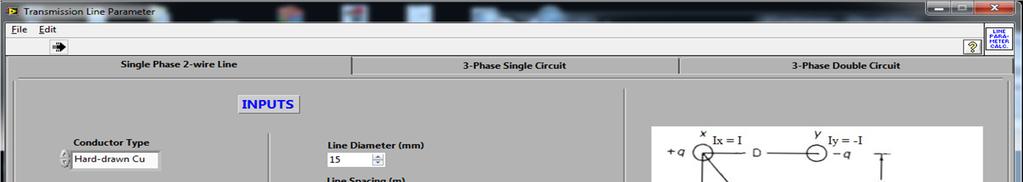
2 bundles, the equation for GMR bundle, up to three conductors per bundle, is defined as: GMR n bundle conductors n 1 1/ ( d GMR ) n = (6) stranded transition of state machines. tate machine infrastructure comprises while loop, case structure, shift register, state functionality code, and transition code (NI LabVIEW, 21). This is shown in Fig 1. For two- subconductor bundle: D ( D d ) = D d b = 4 2 (7) For a three-subconductor bundle: D b 3 2 ( D d d ) = D d = (8) 9 3 where n = number of conductors per bundle GMR = GMR of the stranded conductor stranded d = distance between bundle conductors ρ = conductor resistivity l = length of conductor A = conductor cross sectional area R = ac resistance ac R1 and R 2 = resistances at temperature, t 1 and t 2 V AN = phase a voltage T = temperature constant t1 and t 2 = conductor temperatures λ = flux linkages p I = conductor current µ = constant permeability, π 4 x 7 1 H/m 12 ε = permittivity of free space, 8.85 x 1 F/m r, D = conductor radius and diameter resp. q A = charge on conductor A GMD = geometric mean distance EXPERIMENTAL PROCEDURE A. Architecture A state programming architecture is a good choice in carrying out the routine tasks of different line parameter computation. ometimes, it may be required to change the order of the sequence, repeat one item in the sequence more often than the other items, stop a sequence immediately, or have items in the sequence that may execute only when certain conditions are met. Although a program may not have any such requirements, there is always the possibility that the program must be modified in the future. Therefore, state programming architecture makes future modification an easy task. A state machine relies on user input or in-state calculation to determine which state to go to next. Many applications require an initialization state and a default state, where many different actions can be performed. tate machines are commonly used to create user interfaces where different user actions send the user interface into different processing segments. Each processing segment acts as a state in the state machine. Each segment leads to another segment for further processing or waits for another user action. Enumerated type controls are used to control the initialization and 371 Fig. 1. ystem architecture B. Flowchart The simplified flowchart for the program is given in Fig 2. How the software works is enumerated as follows; it poses two circuit options (single-phase 2-wire line, 3-phase single circuit and 3-phase double circuit) to the user. based on the circuit type, it requests for the necessary inputs from the user; during the input request, it gives both options of a solid conductor and stranded/bundled conductor to the user; and based on the inputs, it computes and displays all the parameters. C. ystem Modules The software calculates each parameter in a separate module. These modules are interconnected in the sense that they all fetch inputs from the same source. Each module is given below. The modules are presented in graphical codes and not textual codes. NI LabVIEW is graphical programming environment that simplifies programming for users just by drag and drop routine. Due to the complexity and space-limitations of that of 3- phase single and double circuits, the modules for singlephase 2-wire line are only presented the next section. The mathematical expressions were used in programming in NI-LabVIEW to calculate overhead electrical power transmission line parameters. The NI- LabVIEW code for Resistance, Inductance, Capacitance, eries Impedance and hunt Admittance are shown in Fig 3 to Fig 6, respectively. REULT AND DICUION Tested with some sets of inputs, the software gives out following results. The snapshots are shown in Figs Fig. 7. shows result of single phase 2-wire line with the following input parameters: conductor type (hard-drawn Aluminum), earth type (average damped earth), temperature ( o C), frequency (6 Hz), line diameter (2 mm 2 ), line spacing (3 m), line height (1 m), solid or bundled (solid), long line length (25 Km).

3 Fig. 2. ystem Flowchart Fig. 3. Resistance Module 372
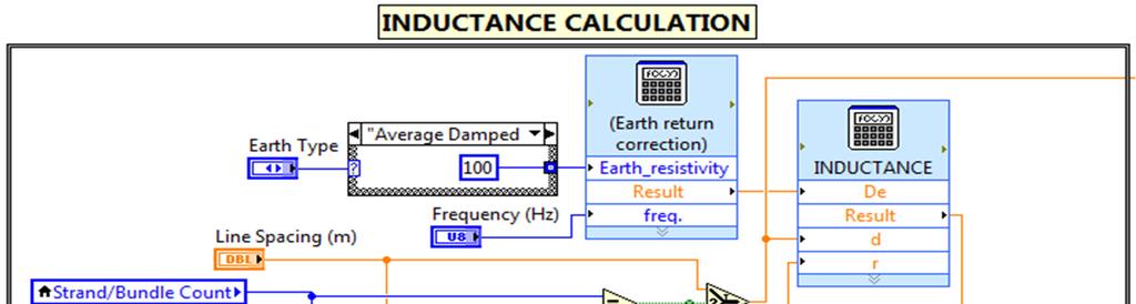
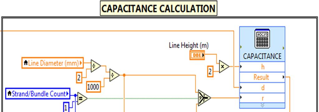
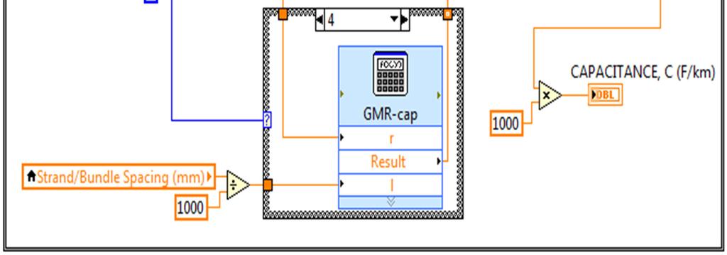
4 Fig. 4. Inductance Module Fig. 5. Capacitance Module 373
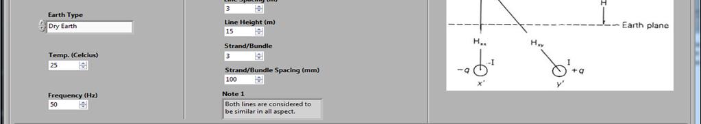
, earth type (dry earth), temperature (o C ), frequency (5 Hz), line diameter (15 mm")
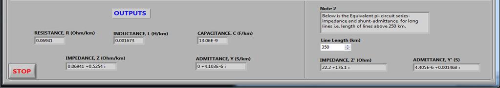
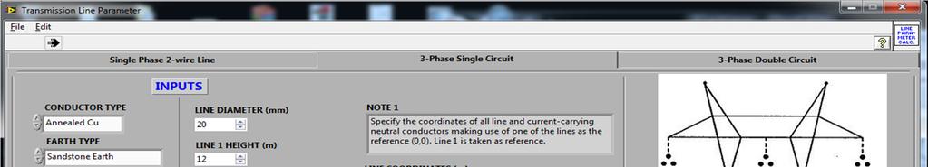
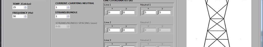
, earth type (sandstone earth), temperature (o C ), frequency (5 Hz), line diameter")
, earth type (dry earth), temperature (o C ), frequency (6 Hz), line diameter")
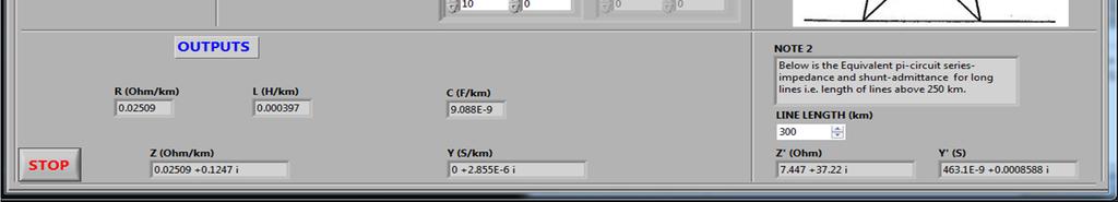
5 Fig. 6. eries Impedance and hunt Admittance for Long Lines Module Fig. 7. ingle-phase 2-Wire Line of 25 Km Length Fig. 8. shows result for single-phase 2-wire line with following set of input parameters: conductor type (harddrawn Copper), earth type (dry earth), temperature (o C ), frequency (5 Hz), line diameter (15 mm 2 ), line spacing (3 m), line height (15 m), solid or bundled (bundled with 3 strands), strand spacing (1 mm), long line length (35 Km). Fig. 9 shows result of 3-phase single circuit line with the following input parameters: conductor type (annealed Copper), earth type (sandstone earth), temperature (o C ), frequency (5 Hz), line diameter (2mm 2 ), line height (12 m), number of neutral or shield wire (1), solid or bundled (solid), long line length (3 Km). Fig. 1 shows result for 3-phase single circuit line with the following input parameters: conductor type (hard-drawn Copper), earth type (dry earth), temperature (o C ), frequency (6 Hz), line diameter (2mm), line 374 height (15m), number of neutral or shield wire (2), solid or bundled (bundled with 3 strands), strand spacing (1mm 2 ), long line length (35 Km). Fig. 11 shows result for 3-phase double circuit line with the following input parameters: conductor type (hard-drawn Copper), earth type (average damped earth), temperature (o C ), frequency (6 Hz), line diameter (25 mm 2 ), line height (2 m), number of neutral or shield wire (2), solid or bundled (solid), long line length (35 Km). Fig. 12 shows result for 3-phase double circuit line with the following input parameters: conductor type (hard-drawn Copper), earth type (dry earth), temperature (o C ), frequency (5 Hz), line diameter (15mm), line height (25m), number of neutral or shield wire (2), solid or bundled (bundled with 2 strands), strand spacing (1mm 2 ), long line length (35 Km).
6 Fig. 8. ingle-phase 2-wire Line with 35 Km Length Fig. 9. Three-phase ingle Circuit Line with 3 Km Length 375


7 Fig. 1. Three-phase ingle Circuit Line with 35 Km Length Fig 11. Three-phase double circuit line with 35 Km Length Fig 12. Three-phase Double Circuit Line with 35 Km Length 376
8 CONCLUION From Figs. 7 and 8, it is observed that the parameters reduce more when dry-earth type was selected for the analysis than the average damped earth type despite increase in line length, it also shows that bundling reduces the parameters values and hence loses in the line. Figs. 9 and 1 also show that the parameters reduce more when dry-earth type was selected for the analysis than the average damped earth type despite increase in line length(sandstone/ dry-earth), though different materials were considered: annealed copper and hard-drawn copper, while Figs 11 and 12, compare hard drawn aluminum with hard-drawn copper but different earth type. The results show that copper (thou a better conductor) has high line parameters than aluminum conductor. Other factors contributing to these are: conductor diameter which increases the inductance. As evident in the result snapshots above, the standalone software is capable of calculating transmission line parameters accurately REFERENCE Das, D. Electrical Power ystems, New Age International (P) Ltd., Publishers, New Delhi, India, 26. Glover, J.D., arma, M.. and Overbye, T.J. Power ystem Analysis and Design, 4th ed. Thomson Learning, Toronto, 28.aadat, H. Power ystem Analysis, 1st ed. McGraw-Hill Companies, Inc., New York, Grainger, J.J. and tevenson (JR.), W.D. Power ystem Analysis, 1st ed. McGraw-Hill, Inc., ingapore, Transmission Line Parameter Calculation, ELEN 459 Power ystem Fault Analysis and Protection, pring 27. EMTP Reference Models for Transmission Line Relay Testing, Final-9/9/25. Lewis, W.A. and Tuttle, P.D. The Resistance and Reactance of Aluminium Conductors teel- Reinforced, AIEE Transactions, III, , Carson, J.R. Wave Propagation in Overhead Wires with Ground Return, Bell ystem Technical Journal, 5, , atsios, K.J., Labridis, D.P., and Dokopoulos, P.. Finite Element Computation of Field and Eddy Currents of a ystem consisting of a Power Transmission Line above Conductors buried in Nonhomogeneous Earth, IEEE Transaction on Power Delivery, 13, , NI LabIEW, Introduction to LabVIEW, National Instrument Corporation,
EE 740 Transmission Lines
 EE 740 Transmission Lines 1 High Voltage Power Lines (overhead) Common voltages in north America: 138, 230, 345, 500, 765 kv Bundled conductors are used in extra-high voltage lines Stranded instead of
EE 340 Transmission Lines. Spring 2012
 EE 340 Transmission Lines Spring 2012 Physical Characteristics Overhead lines An overhead transmission line usually consists of three conductors or bundles of conductors containing the three phases of
EE 340 Transmission Lines
 EE 340 Transmission Lines Physical Characteristics Overhead lines An overhead transmission line usually consists of three conductors or bundles of conductors containing the three phases of the power system.
EE 741. Primary & Secondary Distribution Systems
 EE 741 Primary & Secondary Distribution Systems Radial-Type Primary Feeder Most common, simplest and lowest cost Example of Overhead Primary Feeder Layout Example of Underground Primary Feeder Layout Radial-Type
Transmission of Electrical Energy
 Transmission of Electrical Energy Electrical energy is carries by conductors such as overhead transmission lines and underground cables. The conductors are usually aluminum cable steel reinforced (ACSR),
Simulation and Analysis of Lightning on 345-kV Arrester Platform Ground-Leading Line Models
 International Journal of Electrical & Computer Sciences IJECS-IJENS Vol:15 No:03 39 Simulation and Analysis of Lightning on 345-kV Arrester Platform Ground-Leading Line Models Shen-Wen Hsiao, Shen-Jen
A Study on Electrical Design Considerations of Power Transmission Lines
 A Study on Electrical Design Considerations of Power Transmission Lines Gaddam Siva Ph.D Scholar, Department of Electrical Engineering, SSSUTMS, Sehore, Madhya Pradesh, India ABSTRACT: The power is generated
Fatima Michael college of Engineering and Technology
 Fatima Michael college of Engineering and Technology DEPARTMENT OF ELECTRICAL AND ELECTRONICS ENGINEERING EE2303 TRANSMISSION AND DISTRIBUTION SEM: V Question bank UNIT I INTRODUCTION 1. What is the electric
PRELIMINARIES. Generators and loads are connected together through transmission lines transporting electric power from one place to another.
 TRANSMISSION LINES PRELIMINARIES Generators and loads are connected together through transmission lines transporting electric power from one place to another. Transmission line must, therefore, take power
A Simple Wideband Transmission Line Model
 A Simple Wideband Transmission Line Model Prepared by F. M. Tesche Holcombe Dept. of Electrical and Computer Engineering College of Engineering & Science 337 Fluor Daniel Building Box 34915 Clemson, SC
Improving Power Transfer Capability of EHV AC Double circuit Transmission line by Enhancing Surge Impedance Loading level
 Improving Power Transfer Capability of EHV AC Double circuit Transmission line by Enhancing Surge Impedance Loading level Varun Patel 1, J G Jamnani 2 1,2 School of Technology, Pandit Deendayal Petroleum
Pulse Transmission and Cable Properties ================================
 PHYS 4211 Fall 2005 Last edit: October 2, 2006 T.E. Coan Pulse Transmission and Cable Properties ================================ GOAL To understand how voltage and current pulses are transmitted along
IEEE Power Engineering Society 2001 Winter Meeting Columbus, OH. Panel Session. Data for Modeling System Transients
 IEEE Power Engineering Society 2001 Winter Meeting Columbus, OH Panel Session Data for Modeling System Transients Parameters for Modeling Transmission Lines and Transformers in Transient Studies Bruce
EE2022 Electrical Energy Systems
 EE0 Electrical Energy Systems Lecture : Transformer and Per Unit Analysis 7-0-0 Panida Jirutitijaroen Department of Electrical and Computer Engineering /9/0 EE0: Transformer and Per Unit Analysis by P.
INTEGRATED METHOD IN ELECTROMAGNETIC INTERFERENCE STUDIES
 INTEGRATED METHOD IN ELECTROMAGNETIC INTERFERENCE STUDIES Jinxi Ma and Farid P. Dawalibi Safe Engineering Services & technologies ltd. 1544 Viel, Montreal, Quebec, Canada, H3M 1G4 Tel.: (514) 336-2511
Time-domain electric circuit simulation packages designed for power systems
 Evaluation of rail track impedance and capacitance using the electromagnetic transients program R.J. Hill" & S.R. McKay* "School of Electonic and Electrical Engineering, University of Bath, Claverton Down,
EL 403 MODEL TEST PAPER - 1 POWER SYSTEMS. Time: Three Hours Maximum Marks: 100
 POWER SYSTEMS Time: Three Hours Maximum Marks: 0 Answer five questions, taking ANY TWO from Group A, any two from Group B and all from Group C. All parts of a question (a, b, etc. ) should be answered
Spring 2000 EE361: MIDTERM EXAM 1
 NAME: STUDENT NUMBER: Spring 2000 EE361: MIDTERM EXAM 1 This exam is open book and closed notes. Assume f=60 hz and use the constant µ o =4π 10-7 wherever necessary. Be sure to show all work clearly. 1.
Electricity Supply to Africa and Developing Economies. Challenges and opportunities. Technology solutions and innovations for developing economies
 Electricity Supply to Africa and Developing Economies. Challenges and opportunities. Technology solutions and innovations for developing economies Magnetic induced currents and voltages on earthed lines
Exercises. 6 Exercises
 6 Exercises The following five computer exercises accompany the course. Alternative Transients Program (ATP-EMTP) will be used to compute electrical transients. First electrical network should be created
Modelling of Voltage Regulation Issues in SWER Systems Using PSCAD/EMTDC
 Modelling of Voltage Regulation Issues in SWER Systems Using PSCAD/EMTDC Jason Mayer Connell Wagner Pty Ltd Spring Hill, Queensland, Australia Email: mayerj@conwag.com ABSTRACT An economic (low-cost) distribution
ENHANCEMENT OF POWER FLOW USING SSSC CONTROLLER
 ENHANCEMENT OF POWER FLOW USING SSSC CONTROLLER 1 PRATIK RAO, 2 OMKAR PAWAR, 3 C. L. BHATTAR, 4 RUSHIKESH KHAMBE, 5 PRITHVIRAJ PATIL, 6 KEDAR KULKARNI 1,2,4,5,6 B. Tech Electrical, 3 M. Tech Electrical
Roll No. :... Invigilator s Signature :.. CS/B.TECH(EE)/SEM-5/EE-502/ POWER SYSTEM-I. Time Allotted : 3 Hours Full Marks : 70
/SEM-5/EE-502/ POWER SYSTEM-I. Time Allotted : 3 Hours Full Marks : 70") Name : Roll No. :.... Invigilator s Signature :.. CS/B.TECH(EE)/SEM-5/EE-502/2011-12 2011 POWER SYSTEM-I Time Allotted : 3 Hours Full Marks : 70 The figures in the margin indicate full marks. Candidates
Name : Roll No. :.... Invigilator s Signature :.. CS/B.TECH(EE)/SEM-5/EE-502/2011-12 2011 POWER SYSTEM-I Time Allotted : 3 Hours Full Marks : 70 The figures in the margin indicate full marks. Candidates
2000 Mathematics Subject Classification: 68Uxx/Subject Classification for Computer Science. 281, 242.2
 ACTA UNIVERSITATIS APULENSIS Special Issue SIMULATION OF LIGHTNING OVERVOLTAGES WITH ATP-EMTP AND PSCAD/EMTDC Violeta Chiş, Cristina Băla and Mihaela-Daciana Crăciun Abstract. Currently, several offline
1 Introduction General Background The New Computer Environment Transmission System Developments Theoretical Models and Computer Programs
 Modeling Techniques in Power Systems 1 General Background The New Computer Environment Transmission System Developments Theoretical Models and Computer Programs 2 Transmission Systems Linear Transformation
Extended Transmission Line Loadability Curve by Including Voltage Stability Constrains
 Extended Transmission Line Loadability Curve by Including oltage tability Constrains Jin Hao, Member, IEEE, and Wilsun Xu, Fellow, IEEE Abstract t. Clair curve provides a simple means for estimating power
Level 6 Graduate Diploma in Engineering Electrical Energy Systems
 9210-114 Level 6 Graduate Diploma in Engineering Electrical Energy Systems Sample Paper You should have the following for this examination one answer book non-programmable calculator pen, pencil, ruler,
VARIATION OF LOW VOLTAGE POWER CABLES ELECTRICAL PARAMETERS DUE TO CURRENT FREQUENCY AND EARTH PRESENCE
 VARATON OF LOW VOLTAGE POWER CABLES ELECTRCAL PARAMETERS DUE TO CURRENT FREQUENCY AND EARTH PRESENCE G.T. Andreou, D.P. Labridis, F.A. Apostolou, G.A. Karamanou, M.P. Lachana Aristotle University of Thessaloniki
Dynamic Model Of 400 Kv Line With Distance Relay. Director Research, The MRPC Company, Hyderabad, India 2
 Dynamic Model Of 400 Kv Line With Distance Relay Ramleela Khare 1, Dr Filipe Rodrigues E Melo 2 1 Director Research, The MRPC Company, Hyderabad, India 2 Assoc. Professor Commerce, St. Xavier s College
Electrical Power Systems
 Electrical Power Systems CONCEPT, THEORY AND PRACTICE SECOND EDITION SUBIR RAY Professor MVJ College of Engineering Bangalore PHI Learning Pfcte tofm Delhi-110092 2014 Preface xv Preface to the First Edition
Study of Design of Superconducting Magnetic Energy Storage Coil for Power System Applications
 Study of Design of Superconducting Magnetic Energy Storage Coil for Power System Applications Miss. P. L. Dushing Student, M.E (EPS) Government College of Engineering Aurangabad, INDIA Dr. A. G. Thosar
COMPACT DESIGN AND SIMULATION OF LOW PASS MICROWAVE FILTER ON MICROSTRIP TRANSMISSION LINE AT 2.4 GHz
 International Journal of Management, IT & Engineering Vol. 7 Issue 7, July 2017, ISSN: 2249-0558 Impact Factor: 7.119 Journal Homepage: Double-Blind Peer Reviewed Refereed Open Access International Journal
Radio Frequency Electronics
 Radio Frequency Electronics Preliminaries II Guglielmo Giovanni Maria Marconi Thought off by many people as the inventor of radio Pioneer in long-distance radio communications Shared Nobel Prize in 1909
MODELLING OF BROADBAND POWERLINE COMMUNICATION CHANNELS
 Vol.2(4) December 2 SOUTH AFRICAN INSTITUTE OF ELECTRICAL ENGINEERS 7 MODELLING OF BROADBAND POWERLINE COMMUNICATION CHANNELS C.T. Mulangu, T.J. Afullo and N.M. Ijumba School of Electrical, Electronic
Summary of the Impacts of Grounding on System Protection
 Summary of the Impacts of Grounding on System Protection Grounding System grounding big impact on ability to detect ground faults Common ground options:» Isolated ground (ungrounded)» High impedance ground»
THE PROPAGATION OF PARTIAL DISCHARGE PULSES IN A HIGH VOLTAGE CABLE
 THE PROPAGATION OF PARTIAL DISCHARGE PULSES IN A HIGH VOLTAGE CABLE Z.Liu, B.T.Phung, T.R.Blackburn and R.E.James School of Electrical Engineering and Telecommuniications University of New South Wales
Transmission Line Transient Overvoltages (Travelling Waves on Power Systems)
") Transmission Line Transient Overvoltages (Travelling Waves on Power Systems) The establishment of a potential difference between the conductors of an overhead transmission line is accompanied by the production
Transmission Line Transient Overvoltages (Travelling Waves on Power Systems) The establishment of a potential difference between the conductors of an overhead transmission line is accompanied by the production
Harmonic resonances due to transmission-system cables
 International Conference on Renewable Energies and Power Quality (ICREPQ 14) Cordoba (Spain), 8 th to 1 th April, 214 Renewable Energy and Power Quality Journal (RE&PQJ) ISSN 2172-38 X, No.12, April 214
A Direct Power Controlled and Series Compensated EHV Transmission Line
 A Direct Power Controlled and Series Compensated EHV Transmission Line Andrew Dodson, IEEE Student Member, University of Arkansas, amdodson@uark.edu Roy McCann, IEEE Member, University of Arkansas, rmccann@uark.edu
SHORT CIRCUIT ANALYSIS OF 220/132 KV SUBSTATION BY USING ETAP
 SHORT CIRCUIT ANALYSIS OF 220/132 KV SUBSTATION BY USING ETAP Kiran V. Natkar 1, Naveen Kumar 2 1 Student, M.E., Electrical Power System, MSS CET/ Dr. B.A.M. University, (India) 2 Electrical Power System,
STRAY FLUX AND ITS INFLUENCE ON PROTECTION RELAYS
 1 STRAY FLUX AND ITS INFLUENCE ON PROTECTION RELAYS Z. GAJIĆ S. HOLST D. BONMANN D. BAARS ABB AB, SA Products ABB AB, SA Products ABB AG, Transformers ELEQ bv Sweden Sweden Germany Netherlands zoran.gajic@se.abb.com
Optimal Placement of Shunt Connected Facts Device in a Series Compensated Long Transmission Line
 Journal of Agriculture and Life Sciences Vol. 1, No. 1; June 2014 Optimal Placement of Shunt Connected Facts Device in a Series Compensated Long Transmission Line Sudhakar. Muthyala EEE Dept. University
Analysis of a 405 km transmission line with series compensation
 Analysis of a 405 km transmission line with series compensation by Dr. Rupert Gouws, North-West University This paper presents an investigative case study and energy efficiency analysis of the 405 km,
Factors Affecting the Sheath Losses in Single-Core Underground Power Cables with Two-Points Bonding Method
 International Journal of Electrical and Computer Engineering (IJECE) Vol. 2, No. 1, February 2012, pp. 7~16 ISSN: 2088-8708 7 Factors Affecting the Sheath Losses in Single-Core Underground Power Cables
ENHANCING THE PERFORMANCE OF DISTANCE PROTECTION RELAYS UNDER PRACTICAL OPERATING CONDITIONS
 ENHANCING THE PERFORMANCE OF DISTANCE PROTECTION RELAYS UNDER PRACTICAL OPERATING CONDITIONS by Kerrylynn Rochelle Pillay Submitted in fulfilment of the academic requirements for the Master of Science
CHAPTER 2. Basic Concepts, Three-Phase Review, and Per Unit
 CHAPTER 2 Basic Concepts, Three-Phase Review, and Per Unit 1 AC power versus DC power DC system: - Power delivered to the load does not fluctuate. - If the transmission line is long power is lost in the
ISSN: International Journal of Advanced Research in Computer Engineering & Technology (IJARCET) Volume 2, No 5, May 2013
 Volume 2, No 5, May 2013") 750kv Transmission Line parameter and line Efficiency calculation and the performance of High Voltage alternating current Transmission system using MATLAB program Alka Szeerin Mansoori M.E. Student of
750kv Transmission Line parameter and line Efficiency calculation and the performance of High Voltage alternating current Transmission system using MATLAB program Alka Szeerin Mansoori M.E. Student of
Analysis of lightning performance of 132KV transmission line by application of surge arresters
 Analysis of lightning performance of 132KV transmission line by application of surge arresters S. Mohajer yami *, A. Shayegani akmal, A.Mohseni, A.Majzoobi High Voltage Institute,Tehran University,Iran
MV network design & devices selection EXERCISE BOOK
 MV network design & devices selection EXERCISE BOOK EXERCISES 01 - MV substation architectures 02 - MV substation architectures 03 - Industrial C13-200 MV substation 04 - Max. distance between surge arrester
Distance Protection of Cross-Bonded Transmission Cable-Systems
 Downloaded from vbn.aau.dk on: April 19, 2019 Aalborg Universitet Distance Protection of Cross-Bonded Transmission Cable-Systems Bak, Claus Leth; F. Jensen, Christian Published in: Proceedings of the 12th
Loss of Excitation protection of generator in R-X Scheme
 Volume 03 - Issue 02 February 2017 PP. 37-42 Loss of Excitation protection of generator in R-X Scheme Akshitsinh J. Raulji 1, Ajay M. Patel 2 1 (Electrical Engineering, Birla VishvakarmaMahavidyalaya/
IJSRD - International Journal for Scientific Research & Development Vol. 2, Issue 04, 2014 ISSN (online):
:") IJSRD - International Journal for Scientific Research & Development Vol. 2, Issue 04, 2014 ISSN (online): 2321-0613 Conditioning Monitoring of Transformer Using Sweep Frequency Response for Winding Deformation
IJSRD - International Journal for Scientific Research & Development Vol. 2, Issue 04, 2014 ISSN (online): 2321-0613 Conditioning Monitoring of Transformer Using Sweep Frequency Response for Winding Deformation
EC6503 Transmission Lines and WaveguidesV Semester Question Bank
 UNIT I TRANSMISSION LINE THEORY A line of cascaded T sections & Transmission lines General Solution, Physicasignificance of the equations 1. Derive the two useful forms of equations for voltage and current
from ocean to cloud LAND CABLE INTERFERENCE MODEL AND CABLE CROSSINGS WITH POWER INTERCONNECTS
 LAND CABLE INTERFERENCE MODEL AND CABLE CROSSINGS WITH POWER INTERCONNECTS Mr. Ritesh Dass (Cable&Wireless Worldwide) Email: ritesh.dass@cw.com Cable&Wireless Worldwide, 32-43 Chart Street, London, N1
Parallel Resonance Effect on Conducted Cm Current in Ac/Dc Power Supply
 International Journal of Engineering Science Invention ISSN (Online): 2319 6734, ISSN (Print): 2319 6726 Volume 2 Issue 6 ǁ June. 2013 ǁ PP.31-35 Parallel Resonance Effect on Conducted Cm Current in Ac/Dc
Topic 6 Quiz, February 2017 Impedance and Fault Current Calculations For Radial Systems TLC ONLY!!!!! DUE DATE FOR TLC- February 14, 2017
 Topic 6 Quiz, February 2017 Impedance and Fault Current Calculations For Radial Systems TLC ONLY!!!!! DUE DATE FOR TLC- February 14, 2017 NAME: LOCATION: 1. The primitive self-inductance per foot of length
29 th International Physics Olympiad
 29 th International Physics Olympiad Reykjavik, Iceland Experimental competition Monday, July 6th, 1998 Time available: 5 hours Read this first: Use only the pen provided. 1. Use only the front side of
PHYSICS WORKSHEET CLASS : XII. Topic: Alternating current
 PHYSICS WORKSHEET CLASS : XII Topic: Alternating current 1. What is mean by root mean square value of alternating current? 2. Distinguish between the terms effective value and peak value of an alternating
Modeling and Simulation of Powertrains for Electric and Hybrid Vehicles
 Modeling and Simulation of Powertrains for Electric and Hybrid Vehicles Dr. Marco KLINGLER PSA Peugeot Citroën Vélizy-Villacoublay, FRANCE marco.klingler@mpsa.com FR-AM-5 Background The automotive context
Determination of Optimal Account and Location of Series Compensation and SVS for an AC Transmission System
 ISSN (e): 2250 3005 Vol, 04 Issue, 5 May 2014 International Journal of Computational Engineering Research (IJCER) Determination of Optimal Account and Location of Series Compensation and SVS for an AC
Chapter-5 MODELING OF UNIFIED POWER FLOW CONTROLLER. There are a number of FACTS devices that control power system
 94 Chapter-5 MODELING OF UNIFIED POWER FLOW CONTROLLER 5.1 Introduction There are a number of FACTS devices that control power system parameters to utilize the existing power system and also to enhance
Inductive Conductivity Measurement of Seawater
 Inductive Conductivity Measurement of Seawater Roger W. Pryor, Ph.D. Pryor Knowledge Systems *Corresponding author: 498 Malibu Drive, Bloomfield Hills, MI, 48302-223, rwpryor@pksez.com Abstract: Approximately
Electrical Engineering. Power Systems. Comprehensive Theory with Solved Examples and Practice Questions. Publications
 Electrical Engineering Power Systems Comprehensive Theory with Solved Examples and Practice Questions Publications Publications MADE EASY Publications Corporate Office: 44-A/4, Kalu Sarai (Near Hauz Khas
Simultaneous AC-DC Transmission Scheme Under Unbalanced Load Condition
 Simultaneous AC-DC Transmission Scheme Under Unbalanced Load Condition M. A. Hasan, Priyanshu Raj, Krritika R Patel, Tara Swaraj, Ayush Ansuman Department of Electrical and Electronics Birla Institute
Accurate Current Measurement Transducer for Relaying Purpose
 Accurate Current Measurement Transducer for Relaying Purpose Ashish S. Paramane 1, Dr.P.K.Katti 2 Department of Electrical Engineering Dr. Babasaheb Ambedkar Technological University, Lonere, Maharashtra
Implementing Re-Active Power Compensation Technique in Long Transmission System (750 Km) By Using Shunt Facts Control Device with Mat Lab Simlink Tool
 By Using Shunt Facts Control Device with Mat Lab Simlink Tool") Implementing Re-Active Power Compensation Technique in Long Transmission System (75 Km) By Using Shunt Facts Control Device with Mat Lab Simlink Tool Dabberu.Venkateswara Rao, 1 Bodi.Srikanth 2 1, 2(Department
Implementing Re-Active Power Compensation Technique in Long Transmission System (75 Km) By Using Shunt Facts Control Device with Mat Lab Simlink Tool Dabberu.Venkateswara Rao, 1 Bodi.Srikanth 2 1, 2(Department
 VALLIAMMAI ENGINEERING COLLEGE SRM Nagar, Kattankulathur-603 203 DEPARTMENT OF ELECTRONICS AND COMMUNICATION ENGINEERING EC6503 TRANSMISSION LINES AND WAVEGUIDES YEAR / SEMESTER: III / V ACADEMIC YEAR:
CHAPTER 4 HARMONICS AND POWER FACTOR
 4.1 Harmonics CHAPTER 4 HARMONICS AND POWER FACTOR In this research a comparative study of practical aspects of mixed use of diode and Thyristor converter technologies in Aluminium Smelters has been carried
VALIDATION THROUGH REAL TIME SIMULATION OF A CONTROL AND PROTECTION SYSTEM APPLIED TO A RESONANT EARTHED NEUTRAL NETWORK
 VALIDATION THROUGH REAL TIME SIMULATION OF A CONTROL AND PROTECTION SYSTEM APPLIED TO A RESONANT EARTHED NEUTRAL NETWORK Eduardo MARTÍNEZ eduardo_martinez@fcirce.es Samuel BORROY sborroy@fcirce.es Laura
AEP s 765kV Transmission Line Model Validation for Short Circuit and System Studies. T. YANG, Q. QIU, Z. CAMPBELL American Electric Power USA
 1, rue d Artois, F-75008 PARI CIGRE U National Committee http : //www.cigre.org 015 Grid of the Future ymposium AEP s 765kV Transmission Line Model Validation for hort Circuit and ystem tudies T. YANG,
Investigation of Transmission Line Overvoltages and their Deduction Approach
 Investigation of Transmission Line Overvoltages and their Deduction Approach A. Hayati Soloot, A. Gholami, E. Agheb, A. Ghorbandaeipour, and P. Mokhtari Abstract The two significant overvoltages in power
Identification of weak buses using Voltage Stability Indicator and its voltage profile improvement by using DSTATCOM in radial distribution systems
 IOSR Journal of Electrical And Electronics Engineering (IOSRJEEE) ISSN : 2278-1676 Volume 2, Issue 4 (Sep.-Oct. 2012), PP 17-23 Identification of weak buses using Voltage Stability Indicator and its voltage
Electric Power Systems Research
 Electric Power Systems Research 94 (2013) 54 63 Contents lists available at SciVerse ScienceDirect Electric Power Systems Research j ourna l ho me p a ge: www.elsevier.com/locate/epsr Calculation of overvoltage
Single-turn and multi-turn coil domains in 3D COMSOL. All rights reserved.
 Single-turn and multi-turn coil domains in 3D 2012 COMSOL. All rights reserved. Introduction This tutorial shows how to use the Single-Turn Coil Domain and Multi-Turn Coil Domain features in COMSOL s Magnetic
Experiment 4: Grounding and Shielding
 4-1 Experiment 4: Grounding and Shielding Power System Hot (ed) Neutral (White) Hot (Black) 115V 115V 230V Ground (Green) Service Entrance Load Enclosure Figure 1 Typical residential or commercial AC power
Iron Powder Core Selection For RF Power Applications. Jim Cox Micrometals, Inc. Anaheim, CA
 HOME APPLICATION NOTES Iron Powder Core Selection For RF Power Applications Jim Cox Micrometals, Inc. Anaheim, CA Purpose: The purpose of this article is to present new information that will allow the
Aspects of Network Harmonic Impedance Modelling in High Voltage Distribution Networks
 Aspects of Network Harmonic Impedance Modelling in High Voltage Distribution Networks Diptargha Chakravorty Indian Institute of Technology Delhi (CES) New Delhi, India diptarghachakravorty@gmail.com Jan
Keywords Signal Integrity, micro-strip, crosstalk, NEXT, FEXT.
 Volume 6, Issue 4, April 2016 ISSN: 2277 128X International Journal of Advanced Research in Computer Science and Software Engineering Research Paper Available online at: www.ijarcsse.com Effect of Vias
Conventional Paper-II-2011 Part-1A
 Conventional Paper-II-2011 Part-1A 1(a) (b) (c) (d) (e) (f) (g) (h) The purpose of providing dummy coils in the armature of a DC machine is to: (A) Increase voltage induced (B) Decrease the armature resistance
[Makrariya* et al., 5(8): August, 2016] ISSN: IC Value: 3.00 Impact Factor: 4.116
![[Makrariya* et al., 5(8): August, 2016] ISSN: IC Value: 3.00 Impact Factor: 4.116](/thumbs/81/82632116.jpg "[Makrariya* et al., 5(8): August, 2016] ISSN: IC Value: 3.00 Impact Factor: 4.116") IJESRT INTERNATIONAL JOURNAL OF ENGINEERING SCIENCES & RESEARCH TECHNOLOGY FIVE POLE OPTIMUM DISTRIBUTED HIGH PASS MICROWAVE FILTER: DESIGN ANALYSIS AND SIMULATION ON MICROSTRIP AT 2.4 GHZ Atul Makrariya*,
IJESRT INTERNATIONAL JOURNAL OF ENGINEERING SCIENCES & RESEARCH TECHNOLOGY FIVE POLE OPTIMUM DISTRIBUTED HIGH PASS MICROWAVE FILTER: DESIGN ANALYSIS AND SIMULATION ON MICROSTRIP AT 2.4 GHZ Atul Makrariya*,
ANFIS Approach for Locating Faults in Underground Cables
 Vol:8, No:6, 24 ANFIS Approach for Locating Faults in Underground Cables Magdy B. Eteiba, Wael Ismael Wahba, Shimaa Barakat International Science Index, Electrical and Computer Engineering Vol:8, No:6,
Transmission Line Models Part 1
 Transmission Line Models Part 1 Unlike the electric machines studied so far, transmission lines are characterized by their distributed parameters: distributed resistance, inductance, and capacitance. The
Aligarh College of Engineering & Technology (College Code: 109) Affiliated to UPTU, Approved by AICTE Electrical Engg.
 Affiliated to UPTU, Approved by AICTE Electrical Engg.") Aligarh College of Engineering & Technology (College Code: 19) Electrical Engg. (EE-11/21) Unit-I DC Network Theory 1. Distinguish the following terms: (a) Active and passive elements (b) Linearity and
Aligarh College of Engineering & Technology (College Code: 19) Electrical Engg. (EE-11/21) Unit-I DC Network Theory 1. Distinguish the following terms: (a) Active and passive elements (b) Linearity and
Analysis of the Electromagnetic Interferences between Overhead Power Lines and Buried Pipelines
 Mediterranean Journal of Modeling and Simulation MJMS 1 (214) 13 23 Analysis of the Electromagnetic Interferences between Overhead Power Lines and Buried Pipelines M hamed Ouadah a*, Mourad Zergoug b a
Chapter 2-1 Transformers
 Principles of Electric Machines and Power Electronics Chapter 2-1 Transformers Third Edition P. C. Sen Transformer application 1: power transmission Ideal Transformer Assumptions: 1. Negligible winding
FAULT DETECTION, CLASSIFICATION AND LOCATION ON AN UNDERGROUND CABLE NETWORK USING WAVELET TRANSFORM
 90 FAULT DETECTION, CLASSIFICATION AND LOCATION ON AN UNDERGROUND CABLE NETWORK USING WAVELET TRANSFORM Hashim Hizam, Jasronita Jasni, Mohd Zainal Abidin Ab Kadir, Wan Fatinhamamah Wan Ahmad Department
Current Transformer Performance study Using Software Tools.
 Current Transformer Performance study Using Software Tools. A. Mechraoui, A. Draou, A. Akkouche, and S. AL Ahmadi Department of Electronics Technology Madinah College of Technology, Madinah Council of
A Simple Simulation Model for Analyzing Very Fast Transient Overvoltage in Gas Insulated Switchgear
 A Simple Simulation Model for Analyzing Very Fast Transient Overvoltage in Gas Insulated Switchgear Nguyen Nhat Nam Abstract The paper presents an simple model based on ATP-EMTP software to analyze very
Computation of Inter-turn Voltages in Transformer Windings with Interconnected Distribution Cable
 Computation of Inter-turn Voltages in Transformer Windings with Interconnected Distribution Cable G. Hoogendorp, M. Popov, L. van der Sluis Abstract The paper deals with the use of the hybrid model to
Identification of network models parameters for simulating transients
 Identification of network models parameters for simulating transients D. Cavallera, J-L. Coulomb, O. Chadebec, B. Caillault, F-X. Zgainski and A.Ayroulet Abstract In case of electrical black-out, one of
Design and Simulation of a Quarter Wavelength Gap Coupled Microstrip Patch Antenna
 Design and Simulation of a Quarter Wavelength Gap Coupled Microstrip Patch Antenna Sanjay M. Palhade 1, S. P. Yawale 2 1 Department of Physics, Shri Shivaji College, Akola, India 2 Department of Physics,
Module 1. Introduction. Version 2 EE IIT, Kharagpur
 Module 1 Introduction Lesson 1 Introducing the Course on Basic Electrical Contents 1 Introducing the course (Lesson-1) 4 Introduction... 4 Module-1 Introduction... 4 Module-2 D.C. circuits.. 4 Module-3
Γ L = Γ S =
 TOPIC: Microwave Circuits Q.1 Determine the S parameters of two port network consisting of a series resistance R terminated at its input and output ports by the characteristic impedance Zo. Q.2 Input matching
Placement of shunt FACTS Devices for maximum power transfer capability in a Series Compensated LT Line
 Available Online at http://warse.org/pdfs/2013/ijeter03122013.pdf ABTACT Placement of shunt FACT Devices for maximum power transfer capability in a eries Compensated LT Line K. Vimala Kumar 1, P. Chandra
Transient stability improvement by using shunt FACT device (STATCOM) with Reference Voltage Compensation (RVC) control scheme
 with Reference Voltage Compensation (RVC) control scheme") I J E E E C International Journal of Electrical, Electronics ISSN No. (Online) : 2277-2626 and Computer Engineering 2(1): 7-12(2013) Transient stability improvement by using shunt FACT device (STATCOM)
I J E E E C International Journal of Electrical, Electronics ISSN No. (Online) : 2277-2626 and Computer Engineering 2(1): 7-12(2013) Transient stability improvement by using shunt FACT device (STATCOM)
Frequency Domain Analysis of Capacitor Transient Overvoltages
 Frequency Domain Analysis of Capacitor Transient Overvoltages PATRICIA ROMEIRO DA SILVA JOTA Electrical Engineering Department CEFET-MG Av. Amazonas 7675, 30510-000 Belo Horizonte, Minas Gerais BRAZIL
Module 2 : Current and Voltage Transformers. Lecture 8 : Introduction to VT. Objectives. 8.1 Voltage Transformers 8.1.1Role of Tuning Reactor
 Module 2 : Current and Voltage Transformers Lecture 8 : Introduction to VT Objectives In this lecture we will learn the following: Derive the equivalent circuit of a CCVT. Application of CCVT in power
Analysis and modeling of thyristor controlled series capacitor for the reduction of voltage sag Manisha Chadar
 Analysis and modeling of thyristor controlled series capacitor for the reduction of voltage sag Manisha Chadar Electrical Engineering department, Jabalpur Engineering College Jabalpur, India Abstract:
SIMULATION OF D-Q CONTROL SYSTEM FOR A UNIFIED POWER FLOW CONTROLLER
 SIMULATION OF D-Q CONTROL SYSTEM FOR A UNIFIED POWER FLOW CONTROLLER S. Tara Kalyani 1 and G. Tulasiram Das 1 1 Department of Electrical Engineering, Jawaharlal Nehru Technological University, Hyderabad,
MEASUREMENT OF SURFACE DISPLACEMENT EXCITED BY EMAT TRANSDUCER
 XIX IMEKO World Congress Fundamental and Applied Metrology September 6 11, 29, Lisbon, Portugal MEASUREMENT OF SURFACE DISPLACEMENT EXCITED BY EMAT TRANSDUCER Petr Fidler 1, Petr Beneš 2 1 Brno University