PRUDENT PRACTICES TO IMPROVE POWER FACTOR AND REDUCE POWER LOSS.
|
|
|
- Maximilian Leonard
- 5 years ago
- Views:
Transcription

1 1
2 PRUDENT PRACTICES TO IMPROVE POWER FACTOR AND REDUCE POWER LOSS.
3 DEFINATIONS Working /Active Power: Normally measured in kilowatts (kw). It does the "work" for the system--providing the motion, torque, heat, or whatever else is required. Reactive Power: Normally measured in kilovolt-amperes-reactive (kvar), doesn't do useful "work." It simply sustains the electromagnetic field. Apparent Power: Normally measured in kilovolt-amperes (kva). Working Power and Reactive Power together make up apparent power.
4 POWER FACTOR Power Factor is the ratio between the useful (true) power (kw) to the total (apparent) power (kva) consumed by an item of a.c. electrical equipment or a complete electrical installation. "Power Factor" is an electrical term used to rate the degree of the synchronization of power supply current with the power supply voltage
5 POWER TRIANGLE Active Power (kw)=p Total Power (kva)=s Reactive Power (KVAR)=Q Power Factor = Active (Real) Power Total Power = P (kw) S (kva) = Cosine (θ) = DISPLACEMENT POWER FACTOR
6 LAGGING & LEADING I C I R I R V I LOAD I L G I C L KVAR C KW KVAR L
7 Why Do We Care About Power Factor? Low power factor results in: Poor electrical efficiency Higher utility bills Lower system capacity On the Supply Side, Generation Capacity & Line Losses Increases. Higher Load Currents Higher I²R Losses For Lower Power factor KVA rating of the equipment has to be more which means equipment has to be larger and expensive
8 Improved Power Factor Reduces Power Losses. Before After In this example, demand was reduced to 8250 kva from kva. 1750KVA Transformer Capacity Release. The power factor was improved from 80% to 97%

9 Improved Power Factor Reduces Power Losses. Now with improved power factor to Provide Same Actual Power to the Load Less Apparent Power is Required.
10 METHODS OF POWER FACTOR CORRECTION/ IMPROVMENT Bulk Correction Static Power Factor Correction
11 BULK CORRECTION The Power factor of the total current supplied to the distribution is monitored by a controller which then switches capacitor banks In a fashion to maintain a power factor better than a preset limit. (Typically 0.95) Ideally, the power factor should be as close to unity (Power factor of "1") as possible. There is no problem with bulk correction operating at unity.
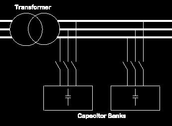
12 BULK CORRECTION
13 STATIC CORRECTION As a large proportion of the inductive or lagging current on the supply is due to the magnetizing current of induction motors, it is easy to correct each individual motor by connecting the correction capacitors to the motor starters. With static correction, it is important that the capacitive current is less than the inductive magnetizing current of the induction motor.
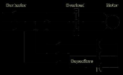
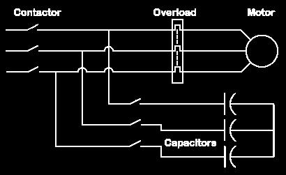
14 STATIC CORRECTION
15 PRUDENT METHODS FOR P.F CORRECTION Static Var Compensator (SVC) Synchronous Condenser
16 STATIC VAR COMPENSATOR (SVC) The Static VAr Compensator is a thyristor controlled (hence static) device which controls the flow of reactive power in a system by generating or absorbing reactive power. The SVC regulates voltage at its terminals by controlling the amount of reactive power injected into or absorbed from the power system.
17 STATIC VAR COMPENSATOR (SVC) When system voltage is low, the SVC generates reactive power (SVC capacitive ). When system voltage is high,it absorbs reactive power (SVC inductive ). Control is achieved by variation of the firing angle of the thyristors.
18 220 KV GRID STATION NEW KOT LAKHPAT 220 KV Bus Bar 3x220/132 kv 250 MVA 132 KV Bus Bar 3x20/26 MVA 132/11 kv T-4 From Saraznagar Cap 1978 A, (Twin Rail) Max. Load 660 A 08/2006 Cap 1095A, Max. Load 800 A T-1 T-5 From Lahore/ SKP From WapdaTown Cap 1978 A, (Twin Rail) Max. Load 660 A 08/2006 Cap 1095 A, Max. Load 800 A T-2 T-6 NKLP-Wapda Town-I NKLP-Wapda Town-II NKLP-Model Town From Bund Road Cap 989 A, (Single Rail) Max. Load 705 A 06/2006 Cap 1095A, Max. Load 780 A T-3 NKLP-Lefo-Model Town NKLP-Defense NKLP-Rehman Park NKLP-Ghazi 10 Nos. 132 kv Circuits NKLP-Old Kot Lakpat NKLP-Wilington Mall NKLP-Town Ship
19 SYNCHRONOUS CONDENSER Synchronous Condenser (sometimes called a synchronous capacitor or synchronous compensator) is a device identical to a synchronous motor, whose shaft is not connected to anything but spins freely. Its purpose is not to convert electric power to mechanical power or vice versa, but to adjust conditions on the power network. Its field is controlled by a voltage regulator to either generate or absorb reactive power as needed to adjust the grid's voltage, or to improve power factor. The condenser s installation and operation are identical to large electric motors.
20 Increasing the device's field excitation results in its furnishing Reactive Power (VARS) to the system. BENEFITS Its principal advantage is the ease with which the amount of correction can be adjusted. The Kinetic Energy stored in the rotor of the machine can help stabilize a power system during Short Circuits or rapidly fluctuating loads such as Electric Arc Furnaces. Eliminate Power Bill Penalties Automatic Power Factor Correction Increase System Stability Mitigate Voltage Transients Reduced System Losses Low Maintenance Costs
21 Harmonics Displacement Power Factor (DPF) Total Power Factor/ True P.F Effects of Harmonics on Capacitors
 is periodic, but not sinusoidal")
22 Linear vs Non-Linear Until recently, most electrical equipment drew current in a linear fashion: v i Current (i) & Voltage (v) are both Sinusoidal Today, many electrical loads draw current in a non-linear fashion: v i Current (i) is periodic, but not sinusoidal
23 WHAT PRODUCES NON-LINEAR CURRENT? Computers Fax Machines M Variable Frequency Drives UPS Copiers Almost anything electronic
24 WHAT PRODUCES NON-LINEAR CURRENT? UPS: Highly Inefficient Generates Harmonics Distorts Power Quality
25 TOTAL HARMONIC CURRENT DISTORTION (THD) IS SAME AS Total Demand Distortion (TDD) I I 2 + I 2 + h 2 I 2 + L I = % = h = 2 TDD I I %
26 TOTAL OR TRUE POWER FACTOR (TPF) TPF = (DPF) x(harm Coefficient) DPF = KW KVA = Cos f Harm Coefficient = TDD 2 TPF = Total or true power factor DPF = Displacement power factor Harm coefficient = Harmonic power factor = Cos d
27 TOTAL POWER FACTOR EXAMPLE VFD ( Six Pulse ) DPF =.95 TDD = 90% ( No Line Reactor) Harm coefficient = 1 = TPF =.95 x.7433 =.7061

28 Applying Capacitors: Caps. at Motors or at SWBD / MCC: Disadvantage: If Drives are present anywhere, the harmonic currents they produce can flow back to the point of lowest impedance: the capacitor! This will cause premature failure of the capacitor. M VFD M M M M
29 HOW HARMONICS AFFECT CAPACITORS Capacitors are naturally a low impedance to high frequencies: Caps. absorb harmonics Caps. do not generate harmonics As capacitor absorbs harmonics, the capacitor heats up Reduced life expectancy Voltage harmonics stress the capacitor dielectric Reduced life expectancy Parallel combination of capacitors with motor or transformer can cause resonance condition
30 RESONANCE The installation of standard capacitors can magnify harmonic currents on the network
31 HOW HARMONICS AFFECT CAPACITORS: Resonance: XL = 2 fl Z fr = f 1 X X L C Resonance X L X C = 1 2 fc fr ( X L -X c ) X C
32 CAPACITOR RESONANCE Resonant Point likely to amplify dominant harmonic (typically 5th) Magnification of Harmonic Current when Standard Capacitor are Added to the Network
33 POWER FACTOR CORRECTION WITH HARMONICS: De-tuning a network: Force the resonant point away from naturally occurring harmonics 4.2 Harmonic (252 Hz) I <h5> Z f I h5 A f 1 f 3 f 5 f 7 f 9 We control the impedance of these two elements
34 POWER LOSS
35 POWER SYSTEM The interconnected facilities of an electrical utility of power system includes generation, transmission, distribution, transformation and productive components necessary to provide service.
36 POWER LOSS It is defined as difference between energy generated in power house and billed on the basis of re-consumption by the consumer connected to that particular power system Mathematically, Energy loss = Energy Generated Energy Billed
37 TYPES OF POWER LOSSES Power Losses Transmission Losses Transformation Losses Distribution Losses
38 TRANSMISSION LOSSES Electricity is transmitted at High Voltages (132kV or above) to reduce the energy lost in long-distance transmission. Power is usually transmitted through overhead Transmission lines. Over head Transmission Lines mostly have technical losses.
39 TRANSMISSION LOSSES Technical Losses are mostly due to the energy dissipated in the Equipment which is Transmission Lines in this case. There are two major sources of loss in high voltage AC transmission lines Resistive loss corona loss
40 TRANSMISSION LOSSES Resistive losses Although the conductors in a transmission line have extremely low resistivity, they are not perfect. Also AC current tends to flow on the surface of the conductor causing skin effect. Resistive losses are = I²R Losses
41 TRANSMISSION LOSSES Corona Losses Corona Losses are caused by the ionization of air molecules near the transmission line conductors. These coronas do not spark across lines, but rather carry current (hence the loss) in the air along the wire. Corona discharge in transmission lines can lead to hissing/cackling
42 REDUCING TRANSMISSION LOSSES
43 TRANSFORMATION LOSSES
44 REDUCING TRANSFORMATION LOSSES Buy low loss transformer Don t Go for the initial cost of transformer Low cost transformer might have higher transformation losses which causes losses for the rest of the operating life. Don t operate transformer on overload because losses = I²R
45 Distribution Losses Distribution losses refers to the losses occurring during the process of delivering electrical energy from 11kV feeder to the specific locations like residential homes and industries.
46 Types Of Distribution Losses Administrative Losses (Theft) Technical Losses
47 Causes of Technical Losses Sub standard and under sized conductor Low power factor Over loading of transformers Over loading of conductor and cable Lengthy Lines Unplanned Substandard System Low Frequency Substandard Repair of Distribution Transformers.
48 Remedial Measures Re-conductoring Bifurcation of feeders Adding new grids Providing additional transformers Balance Loading of transformers Adequate preventive maintenance
49 Administrative Distribution Losses Administrative losses are caused by lack of administration, financial constraints, theft, defective meter and error in meter reading and in estimating unmetered supply of energy.
50 Causes of Administrative Losses On the part of Organization On the part of Customers
51 On the Part of Organization Metering Equipment Sub standard energy meters Defective energy meters Non replacement/ calibration of energy meters Un secured energy meters
52 Remedial Measures to Control Administrative Losses Metering equipment including testing set Accurate Meter reading and billing Replacing faulty meters. Shift to pre-paid card system Checking of energy meters


53
World Academy of Science, Engineering and Technology International Journal of Electrical and Computer Engineering Vol:7, No:6, 2013
 Investigating the Effect of Using Capacitorsin the Pumping Station on the Harmonic Contents (Case Study: Kafr El-Shikh Governorate, Egypt) Khaled M. Fetyan Abstract Power Factor (PF) is one of the most
Power Factor. Power Factor Correction.
 Power Factor. Power factor is the ratio between the KW and the KVA drawn by an electrical load where the KW is the actual load power and the KVA is the apparent load power. It is a measure of how effectively
Thyristorised Automatic Power Factor
 Thyristorised Automatic Power Factor Correction with 7% D Tune Harmonics Suppression (Reactor/Filtering) System Power quality? In the present Low voltage (LV) industrial distribution system the power factor
IMPROVING POWER QUALITY AND ENHANCING THE LIFE OF POWER EQUIPMENT, IN RAILWAY TSSs
 IMPROVING POWER QUALITY AND ENHANCING THE LIFE OF POWER EQUIPMENT, IN RAILWAY TSSs Mr. P. Biswas, ABB ABSTRACT The Indian Railways employ single phase 25 kv Traction sub-station (TSS) for supplying power
HARMONICS CAUSES AND EFFECTS
 HARMONICS CAUSES AND EFFECTS What is Harmonics? Harmonics is defined as the content of the signal whose frequency is an integral multiple of the system frequency of the fundamentals. Harmonics current
ELG 4125: ELECTRICAL POWER TRANSMISSION AND DISTRIBUTION: TUTORIAL 1: - BY:
 ELG 4125: ELECTRICAL POWER TRANSMISSION AND DISTRIBUTION: TUTORIAL 1: - BY: Faizhussain Arsiwala POWER FACTOR: The cosine of angle between voltage and current in an a.c. circuit is known as power factor.
HARMONICS THE BASICS H A R M O N I C M I T I G A T I O N A N D D I S P L A C E M E N T P O W E R F A C T O R C O R R E C T I O N
 HARMONICS THE BASICS H A R M O N I C M I T I G A T I O N A N D D I S P L A C E M E N T P O W E R F A C T O R C O R R E C T I O N Harmonic Basics 3 rd Harmonic Fundamental 5 t1h Harmonic 7 th Harmonic Harmonic
CHAPTER 4 HARMONICS AND POWER FACTOR
 4.1 Harmonics CHAPTER 4 HARMONICS AND POWER FACTOR In this research a comparative study of practical aspects of mixed use of diode and Thyristor converter technologies in Aluminium Smelters has been carried
Welcome to the rd. Annual Northern Ohio. 3 rd Energy Management Conference September 30, 2008
 Welcome to the rd Annual Northern Ohio 3 rd Energy Management Conference September 30, 2008 Recover Lost Dollars Demand Side Electrical Energy Savings By Improving Distribution System Efficiency, Capacity
Technical News. Part 2: Harmonics. The link between harmonics and power factor. Industrial Electrical and Automation Products, Systems and Solutions
 Issue #65 - December 2012 Technical News Industrial Electrical and Automation Products, Systems and Solutions Part 2: Harmonics The link between harmonics and power factor Written by Justin Charlot Product
7/15/2002 PP.AFD.08 1 of 28
 Power Quality Considerations When Applying Adjustable Frequency Drives Explanations and Various Countermeasures 7/15/2002 PP.AFD.08 1 of 28 Power Quality Why the Renewed Interest in Power Quality? Copy
Generator Advanced Concepts
 Generator Advanced Concepts Common Topics, The Practical Side Machine Output Voltage Equation Pitch Harmonics Circulating Currents when Paralleling Reactances and Time Constants Three Generator Curves
How Harmonics have led to 6 Power Factor Misconceptions
 Harmonic and Energy Saving Solutions How Harmonics have led to 6 Power Factor Misconceptions Tony Hoevenaars, P.Eng. Power Factor Misconceptions 1. Low power factor is normally caused by electric motors
ENERGY SAVINGS THROUGH POWER CONDITIONING WITH THE PowerGUARD SYSTEM
 ENERGY SAVINGS THROUGH POWER CONDITIONING WITH THE PowerGUARD SYSTEM Abstract Efficient operation of the electrical system of any facility is essential to controlling operational costs while maximizing
THE COMPREHENSIVE APPROACH TO FACILITY POWER QUALITY
 by Cesar Chavez, Engineering Manager, Arteche / Inelap, and John Houdek, President, Allied Industrial Marketing, Inc. Abstract: Industrial facility harmonic distortion problems can surface in many different
EH2741 Communication and Control in Electric Power Systems Lecture 2
 KTH ROYAL INSTITUTE OF TECHNOLOGY EH2741 Communication and Control in Electric Power Systems Lecture 2 Lars Nordström larsno@kth.se Course map Outline Transmission Grids vs Distribution grids Primary Equipment
Harmonics and Their Impact on Power Quality. Wayne Walcott Application Engineering Manager June, 2017
 Harmonics and Their Impact on Power Quality Wayne Walcott Application Engineering Manager June, 2017 Presentation Overview A little about harmonics What are harmonics What are NOT harmonics What creates
Power Quality Analysis in Power System with Non Linear Load
 International Journal of Electrical Engineering. ISSN 0974-2158 Volume 10, Number 1 (2017), pp. 33-45 International Research Publication House http://www.irphouse.com Power Quality Analysis in Power System
ARDUINO BASED POWER FACTOR CORRECTION
 ARDUINO BASED POWER FACTOR CORRECTION 1 SHOBHA R.MANE, 2 ASHWINI A.KOLEKAR, 3 MAITHILI M. MOLAJ, 4 SADHANA V.PATIL, 5 MAZHARHUSSAIN N. MESTRI 1,2,3,4,5 Electrical Department, Shivaji University, Kolhapur,
ECE 422/522 Power System Operations & Planning/Power Systems Analysis II 5 - Reactive Power and Voltage Control
 ECE 422/522 Power System Operations & Planning/Power Systems Analysis II 5 - Reactive Power and Voltage Control Spring 2014 Instructor: Kai Sun 1 References Saadat s Chapters 12.6 ~12.7 Kundur s Sections
DSP-BASED CURRENT SHARING OF AVERAGE CURRENT CONTROLLED TWO-CELL INTERLEAVED BOOST POWER FACTOR CORRECTION CONVERTER
 DSP-BASED CURRENT SHARING OF AVERAGE CURRENT CONTROLLED TWO-CELL INTERLEAVED BOOST POWER FACTOR CORRECTION CONVERTER P.R.Hujband 1, Dr. B.E.Kushare 2 1 Department of Electrical Engineering, K.K.W.I.E.E.R,
Power Factor improved by Variable Speed AC Drives By Mauri Peltola, ABB Oy, Drives
 For your business and technology editors Power Factor improved by Variable Speed AC Drives By Mauri Peltola, ABB Oy, Drives The use of AC induction motors is essential for industry and utilities. AC induction
POWER FACTOR CORRECTION AND ITS PITFALLS
 Technical Note No. May 1999 POWER FACTOR CORRECTION AND ITS PITFALLS This Technical Note considers power factor correction as applied by large customers and the possible consequences when power factor
CHAPTER 3 IMPROVEMENT OF LOAD POWER FACTOR USING FACTS CONTROLLERS
 40 CHAPTER 3 IMPROVEMENT OF LOAD POWER FACTOR USING FACTS CONTROLLERS 3.1 INTRODUCTION The low power factor effects on transmission line, switchgear, transformers etc. It is observed that if the power
Sizing Generators for Leading Power Factor
 Sizing Generators for Leading Power Factor Allen Windhorn Kato Engineering 24 February, 2014 Generator Operation with a Leading Power Factor Generators operating with a leading power factor may experience
Active Harmonic Filter (AF3)
") Active Harmonic Filter (AF3) Active Harmonic Filter Improving the Efficiency and Life of System by use of Digital Active Power Conditioner HARMONICS 50 Hz, fundamental 100 Hz, 2nd Harmonic 150 Hz, 3rd
Active Harmonic Filter (AF3) Active Harmonic Filter Improving the Efficiency and Life of System by use of Digital Active Power Conditioner HARMONICS 50 Hz, fundamental 100 Hz, 2nd Harmonic 150 Hz, 3rd
ABB DRIVES Technical guide No. 6 Guide to harmonics with AC drives
 ABB DRIVES Technical guide No. 6 Guide to harmonics with AC drives 2 TECHNICAL GUIDE NO. 6 GUIDE TO HARMONICS WITH AC DRIVES Guide to harmonics This guide is part of ABB s technical guide series, describing
Harmonic control devices
 ECE 528 Understanding Power Quality http://www.ece.uidaho.edu/ee/power/ece528/ Paul Ortmann portmann@uidaho.edu 208-733-7972 (voice) Lecture 24 1 Today Harmonic control devices In-line reactors (chokes)
LV PFC Basics. Power Factor Correction - Basics FK PC PM PFC Januar 07 Page: 1
 LV PFC Basics Power Factor Correction - Basics FK PC PM PFC Januar 07 Page: 1 What are the different types of loads? Ohmic loads Lighting bulbs Iron Resistive heating Capacative loads Capacitors Underground
Simulation & Hardware Implementation of APFC Meter to Boost Up Power Factor Maintain by Industry.
 Simulation & Hardware Implementation of APFC Meter to Boost Up Power Factor Maintain by Industry. Bhargav Jayswal 1, Vivek Khushwaha 2, Prof. Pushpa Bhatiya 3 1.2 B. E Electrical Engineering, Vadodara
Electrical Theory. Power Principles and Phase Angle. PJM State & Member Training Dept. PJM /22/2018
 Electrical Theory Power Principles and Phase Angle PJM State & Member Training Dept. PJM 2018 Objectives At the end of this presentation the learner will be able to: Identify the characteristics of Sine
Automatic Power Factor Correction by Using Synchronous Condenser with Continuous Monitoring.
 Automatic Power Factor Correction by Using Synchronous Condenser with Continuous Monitoring. Rosni Sayed Rajshahi University of Engineering & Technology Rajshahi-6204 Bangladesh A.H.M Iftekharul Ferdous
DATA SHEET POWER CAPACITOR
 Issued August 2009 10470 DATA SHEET POWER CAPACITOR General Data * POWER FACTOR CORRECTION The power factor of a load is defined as the ratio of active power to apparent power, i.e. kw : kva and is referred
Joe Warner, Electric Power Industry Conference (EPIC), November 15, 2016 Advances in Grid Equipment Transmission Shunt Compensation
, November 15, 2016 Advances in Grid Equipment Transmission Shunt Compensation") Joe Warner, Electric Power Industry Conference (EPIC), November 15, 2016 Advances in Grid Equipment Transmission Shunt Compensation Slide 1 Excerpt from the BoA BoA: Book of Acronyms MSC/MSR: Mechanically
Joe Warner, Electric Power Industry Conference (EPIC), November 15, 2016 Advances in Grid Equipment Transmission Shunt Compensation Slide 1 Excerpt from the BoA BoA: Book of Acronyms MSC/MSR: Mechanically
ELEKTROTEHNI KO PODJETJE Leskoπkova cesta 12, 1000 Ljubljana, SLOVENIA
 d.o.o. ELEKTROTEHNI KO PODJETJE Leskoπkova cesta 12, 1000 Ljubljana, SLOVENIA SETTING UP REACTIVE POWER COMPENSATION DEVICES SELECTING A REACTIVE POWER COMPENSATION DEVICE To effectively compensate the
ARE HARMONICS STILL A PROBLEM IN DATA CENTERS? by Mohammad Al Rawashdeh, Lead Consultant, Data Center Engineering Services
 ARE HARMONICS STILL A PROBLEM IN DATA CENTERS? by Mohammad Al Rawashdeh, Lead Consultant, Data Center Engineering Services edarat group INTRODUCTION Harmonics are a mathematical way of describing distortion
ISSN: ISO 9001:2008 Certified International Journal of Engineering and Innovative Technology (IJEIT) Volume 5, Issue 11, May 2016
 Volume 5, Issue 11, May 2016") Power Loss Minimization In Distribution System Using Static VAR Compansator Mohamed Hussien Zahran, Hamdy A. M. Shatla, Salama Abo_Zead Dept. of Electrical Engineering, Al-Azhar University, Cairo, Egypt
Power Loss Minimization In Distribution System Using Static VAR Compansator Mohamed Hussien Zahran, Hamdy A. M. Shatla, Salama Abo_Zead Dept. of Electrical Engineering, Al-Azhar University, Cairo, Egypt
Analysis of Harmonic Distortion in Non-linear Loads
 Analysis of Harmonic Distortion in Non-linear Loads Anne Ko Department of Electrical Power Engineering Mandalay Technological University, Mandalay, Myanmar.Phone:+95-09-2225761 anneko101082@gmail.com Wunna
3/29/2012 MAIN TOPICS DISCUSSED ELECTRICAL SYSTEMS AND ELECTRIC ENERGY MANAGEMENT SECTION K ELECTRIC RATES POWER COMPUTATION FORMULAS.
 MAIN TOPICS DISCUSSED Electric Rates Electrical system utilization ELECTRICAL SYSTEMS AND ELECTRIC ENERGY MANAGEMENT SECTION K Power quality Harmonics Power factor (Cos phi) improvement Section K - 2 ELECTRIC
Chapter L Power factor correction and harmonic filtering
 Chapter L Power factor correction and 1 2 3 4 5 6 7 8 9 10 Contents Reactive energy and power factor 1.1 The nature of reactive energy L2 1.2 Equipment and appliances requiring reactive energy L2 1.3 The
Effects of Harmonic Distortion I
 Effects of Harmonic Distortion I Harmonic currents produced by nonlinear loads are injected back into the supply systems. These currents can interact adversely with a wide range of power system equipment,
PQ for Industrial Benchmarking with various methods to improve. Tushar Mogre.
 General PQ: Power Quality has multiple issues involved. Thus, need to have some benchmarking standards. Very little is spoken about the LT supply installation within an industry. There is need to understand
BUFFALO ENERGY SCIENCE AND TECHNOLOGY GROUP
 The BEST Group THE BUFFALO ENERGY SCIENCE AND TECHNOLOGY GROUP -Winter Lecture Series HARMONICS Presented by: Syed Khundmir T Department of Electrical Engineering University at Buffalo khundmir@buffalo.edu
CHAPTER 5 POWER QUALITY IMPROVEMENT BY USING POWER ACTIVE FILTERS
 86 CHAPTER 5 POWER QUALITY IMPROVEMENT BY USING POWER ACTIVE FILTERS 5.1 POWER QUALITY IMPROVEMENT This chapter deals with the harmonic elimination in Power System by adopting various methods. Due to the
AC Power Instructor Notes
 Chapter 7: AC Power Instructor Notes Chapter 7 surveys important aspects of electric power. Coverage of Chapter 7 can take place immediately following Chapter 4, or as part of a later course on energy
Impact of Distributed Generation on Network Voltage Levels
 EEE8052 Distributed Generation Taster Material Impact of Distributed Generation on Network Voltage Levels Steady-state rise in network voltage levels Existing practice is to control distribution voltage
A Thyristor Controlled Three Winding Transformer as a Static Var Compensator
 Abstract: A Thyristor Controlled Three Winding Transformer as a Static Var Compensator Vijay Bendre, Prof. Pat Bodger, Dr. Alan Wood. Department of Electrical and Computer Engineering, The University of
Enhancement of Voltage Stability & reactive Power Control of Distribution System Using Facts Devices
 Enhancement of Voltage Stability & reactive Power Control of Distribution System Using Facts Devices Aarti Rai Electrical & Electronics Engineering, Chhattisgarh Swami Vivekananda Technical University,
Dynamic Harmonic Mitigation and Power Factor Correction
 Dynamic Harmonic itigation and Power Factor Correction Cesar Chavez, Eng Engineering Dept., Arteche. Naucalpan, Edo. de éxico, éxico John A. Houdek, ember, IEEE President, Allied Industrial arketing ilwaukee,
SRI VIDYA COLLEGE OF ENGG AND TECH
 EEE6603 PSOC Page 1 UNIT-III REACTIVE POWER VOLTAGE CONTROL 1. List the various components of AVR loop? The components of automatic voltage regulator loop are exciter, comparator, amplifier, rectifier
APPLICATION NOTE. Applying Type DD60 Capacitors in Harmonic Filter Applications. Total Power Factor PF = cosine ɸ
 APPLICATION NOTE SEPTEMBER 12, 2017 F-AN-001 FRAKO North America W67N222 Evergreen Bvd Suite 209 Cedarburg, WI 53012 Phone: 1-262-618-2403 Fax: 1-262-618-2303 www.frako.de Applying Type DD60 Capacitors
Chapter 7. Copyright The McGraw-Hill Companies, Inc. Permission required for reproduction or display.
 Chapter 7 Copyright The McGraw-Hill Companies, Inc. Permission required for reproduction or display. Learning Objectives 1. Understand the meaning of instantaneous and average power, master AC power notation,
Reducing Total Harmonic Distortion with Variable Frequency Drives
 Reducing Total Harmonic Distortion with Variable Frequency Drives Low Harmonic Technology in Optidrive Eco Overview Overview Both AC line chokes and DC link chokes have historically been used with Variable
CONTENTS. 1. Introduction Generating Stations 9 40
 CONTENTS 1. Introduction 1 8 Importance of Electrical Energy Generation of Electrical Energy Sources of Energy Comparison of Energy Sources Units of Energy Relationship among Energy Units Efficiency Calorific
ENERGY SAVING WITH OPTIMIZATION OF VOLTAGE AND CURRENT QUALITY
 ENERGY SAVING WITH OPTIMIZATION OF VOLTAGE AND CURRENT QUALITY Approximation based on the know-how of SEMAN S.A. The non-linear nature of modern electric loads makes the reception of measures for the confrontation
Impact Assessment Generator Form
 Impact Assessment Generator Form This connection impact assessment form provides information for the Connection Assessment and Connection Cost Estimate. Date: (dd/mm/yyyy) Consultant/Developer Name: Project
McGill Power Sales & Engineering, INC.
 1 McGill Power Sales & Engineering, INC. Power Factor Correction Terry McGill President McGill Power Sales & Engineering Inc. 2007 Eaton Corporation. All rights reserved. Agenda What is power factor? What
PQ01. Harmonic Solutions for VFD s. Review of Power Control Harmonics, Power Factor, Distortion & Displacement
 PQ01 Harmonic Solutions for VFD s Review of Power Control Harmonics, Power Factor, Distortion & Displacement Related Content at the Expo PQ02 Power Quality and Monitoring.. PQ03 Using Test Eqipment to
Power Factor & Harmonics
 Power Factor & Harmonics Andy Angrick 2014 Harmonic Distortion Harmonic problems are becoming more apparent because more equipment that produce harmonics are being applied to power systems Grounding Harmonics
Effective Harmonic Mitigation with Active Filters
 Advancing Power Quality White Paper Effective Harmonic Mitigation with Active Filters Written by: Ian Wallace Variable Speed Drive with no Harmonic Mitigation Industry standard variable speed drives, with
Low Pass Harmonic Filters
 Exclusive e-rated Provider PRODUCT SHEET HARMITIGATOR TM Low Pass Harmonic Filters A solution for electrical distribution systems that require stable, reliable power, characterized by unparalleled power
Harmonic Solutions in Electrical Systems. Raed Odeh Application Specialist - Power Quality & Electrical Distribution
 Harmonic Solutions in Electrical Systems Raed Odeh Application Specialist - Power Quality & Electrical Distribution Agenda I. Harmonic Basics II.Harmonic Mitigation Solutions III.Case Study 2 Harmonic
Technical Report. Zero Reactive Power Passive Current Harmonic Filter (ZRPPCHF) (In House Case Study) Prepared by. Dr. V. R. Kanetkar.
 (In House Case Study) Prepared by. Dr. V. R. Kanetkar.") Technical Report on Zero Reactive Power Passive Current Harmonic Filter (ZRPPCHF) (In House Case Study) Prepared by Dr. V. R. Kanetkar (February 2015) Shreem Electric Limited (Plot No. 43-46, L. K. Akiwate
Technical Report on Zero Reactive Power Passive Current Harmonic Filter (ZRPPCHF) (In House Case Study) Prepared by Dr. V. R. Kanetkar (February 2015) Shreem Electric Limited (Plot No. 43-46, L. K. Akiwate
Power Conditioning Equipment for Improvement of Power Quality in Distribution Systems M. Weinhold R. Zurowski T. Mangold L. Voss
 Power Conditioning Equipment for Improvement of Power Quality in Distribution Systems M. Weinhold R. Zurowski T. Mangold L. Voss Siemens AG, EV NP3 P.O. Box 3220 91050 Erlangen, Germany e-mail: Michael.Weinhold@erls04.siemens.de
Owner/Customer Name: Mailing Address: City: County: State: Zip Code: Phone Number: Representative: Address: Fax Number:
 Interconnection of a Customer-Owned Renewable Generation System of Greater than 100 KW and Less than or Equal to 1 MW to the LCEC Electric Grid Tier 3 Application and Compliance Form Instructions: Complete
POWER SYSTEMS QUALITY Topic 5: Principles for Controlling Harmonics
 POWER SYSTEMS QUALITY Topic 5: Principles for Controlling Harmonics EE589-Power System Quality & Harmonics Electrical Engineering Department School of Engineering University of Jordan 1 Control of Harmonics
ECET Modern Power
 ECET 273000 Modern Power Course Instructors Course Philosophy This course is an introduction to a wide range of electrical energy systems technologies. Topics include fundamentals of energy conversion,
Understanding Input Harmonics and Techniques to Mitigate Them
 Understanding Input Harmonics and Techniques to Mitigate Them Mahesh M. Swamy Yaskawa Electric America YASKAWA Page. 1 Organization Introduction Why FDs Generate Harmonics? Harmonic Limit Calculations
International Journal of Emerging Technology in Computer Science & Electronics (IJETCSE) ISSN: Volume 8 Issue 1 APRIL 2014.
 ISSN: Volume 8 Issue 1 APRIL 2014.") WIND TURBINE VOLTAGE STABILITY USING FACTS DEVICE PRAVEEN KUMAR.R# and C.VENKATESH KUMAR* #M.E.POWER SYSTEMS ENGINEERING, EEE, St. Joseph s college of engineering, Chennai, India. *Asst.Professor, Department
WIND TURBINE VOLTAGE STABILITY USING FACTS DEVICE PRAVEEN KUMAR.R# and C.VENKATESH KUMAR* #M.E.POWER SYSTEMS ENGINEERING, EEE, St. Joseph s college of engineering, Chennai, India. *Asst.Professor, Department
The Impact of Connecting Distributed Generation to the Distribution System E. V. Mgaya, Z. Müller
 The Impact of Connecting Distributed Generation to the Distribution System E. V. Mgaya, Z. Müller This paper deals with the general problem of utilizing of renewable energy sources to generate electric
CHAPTER 6 UNIT VECTOR GENERATION FOR DETECTING VOLTAGE ANGLE
 98 CHAPTER 6 UNIT VECTOR GENERATION FOR DETECTING VOLTAGE ANGLE 6.1 INTRODUCTION Process industries use wide range of variable speed motor drives, air conditioning plants, uninterrupted power supply systems
Power Quality Monitoring and Power Metering Tutorial
 Power Quality Monitoring and Power Metering Tutorial Power generation and transmission today are accomplished using three phase alternatingcurrent. To understand electrical power quality monitoring and
Power Quality enhancement of a distribution line with DSTATCOM
 ower Quality enhancement of a distribution line with DSTATCOM Divya arashar 1 Department of Electrical Engineering BSACET Mathura INDIA Aseem Chandel 2 SMIEEE,Deepak arashar 3 Department of Electrical
Application Guidance Notes: Technical Information from Cummins Generator Technologies
 Application Guidance Notes: Technical Information from Cummins Generator Technologies AGN 087 Power Factor DEFINITIONS What is Power Factor? Power factor is a way of identifying the electrical relationship
Improvement in Power Quality of Distribution System Using STATCOM
 Improvement in Power Quality of Distribution System Using STATCOM 1 Pushpa Chakravarty, 2 Dr. A.K. Sharma 1 M.E. Scholar, Depart. of Electrical Engineering, Jabalpur Engineering College, Jabalpur, India.
International Journal of Advance Engineering and Research Development ANALYSIS AND MITIGATION OF HARMONICS IN MEDICAL FIELD
 Scientific Journal of Impact (SJIF): 5.71 International Journal of Advance Engineering and Research Development Volume 5, Issue 04, April -2018 e-issn (O): 2348-4470 p-issn (P): 2348-6406 ANALYSIS AND
VARIABLE FREQUENCY DRIVE
 VARIABLE FREQUENCY DRIVE Yatindra Lohomi 1, Nishank Nama 2, Umesh Kumar 3, Nosheen aara 4, Uday Raj 5 (Assistant Professor in Department of Electrical Engineering GIET Kota2) (Department of Electrical
POWER FACTOR CORRECTION USING BOOST CONVERTER
 POWER FACTOR CORRECTION USING BOOST CONVERTER Hiten Pahilwani Accenture Services, Mumbai 400708 ABSTRACT In an electrical Power systems, a load with a low power factor draws more current than a load with
SHUNT ACTIVE POWER FILTER
 75 CHAPTER 4 SHUNT ACTIVE POWER FILTER Abstract A synchronous logic based Phase angle control method pulse width modulation (PWM) algorithm is proposed for three phase Shunt Active Power Filter (SAPF)
Harmonic Distortion Effects and Mitigation in Distribution Systems
 Journal of American Science 00;6(0) Harmonic Distortion Effects and Mitigation in Distribution Systems Hussein A. Attia, M. El-Metwally and Osama M. Fahmy Cairo University, Faculty of Engineering, Electrical
Highgate Converter Overview. Prepared by Joshua Burroughs & Jeff Carrara IEEE PES
 Highgate Converter Overview Prepared by Joshua Burroughs & Jeff Carrara IEEE PES Highgate Converter Abstract Introduction to HVDC Background on Highgate Operation and Control schemes of Highgate 22 Why
Harmonic Analysis and Its Mitigation Using Different Passive Filters
 Harmonic Analysis and Its Mitigation Using Different Passive Filters Ashlin Gloria Reginald 1, K J Thomas 2 1 PG Scholar, Amal Jyothi College of Engineering, Kanjirapally Kottayam, India ashlingloriar@gmail.com
P2 Power Solutions Pvt. Ltd. P2 Power Magnetics. Quality Power within your Reach. An ISO 9001:2008 Company
 P2 Power Solutions Pvt. Ltd. An ISO 9001:2008 Company Quality Power within your Reach P2 Power Magnetics P2 Power Solutions Pvt. Ltd. P2 Power Solutions Pvt. Ltd. provides EMC and power quality solutions,
Reactors for filtering
 NEW ZEALAND WWW.LPINZ.CO.NZ Unit 6/22 Moselle Ave, Henderson, Auckland, New Zealand PO Box 21-872, Henderson, Auckland, New Zealand Phone:+64 9 833 5749 Email:info@LPINZ.co.nz Web: www.lpinz.co.nz Reactors
Technical Application Papers No.8 Power factor correction and harmonic filtering in electrical plants
 Technical Application Papers No.8 Power factor correction and harmonic filtering in electrical plants Index Technical Application Papers Power factor correction and harmonic filtering in electrical plants
CHAPTER 4 POWER QUALITY AND VAR COMPENSATION IN DISTRIBUTION SYSTEMS
 84 CHAPTER 4 POWER QUALITY AND VAR COMPENSATION IN DISTRIBUTION SYSTEMS 4.1 INTRODUCTION Now a days, the growth of digital economy implies a widespread use of electronic equipment not only in the industrial
SOUTH CENTRAL INDIANA REMC Application for Operation of Member-Owned Small Power Generation Systems
 SOUTH CENTRAL INDIANA REMC Application for Operation of Member-Owned Small Power Generation Systems This application should be completed as soon as possible and returned to the Cooperative in order to
DESIGN AND ANALYSIS OF ELIMINATION OF HARMONICS USING WIND ENERGY CONVERSION SYSTEMS
 DESIGN AND ANALYSIS OF ELIMINATION OF HARMONICS USING WIND ENERGY CONVERSION SYSTEMS Dr.S.K.PURUSHOTHAMAN Associate Professor Department of EEE Sri Venkateswara College Of Engineering And Technology, Thirupachur
Investigation of D-Statcom Operation in Electric Distribution System
 J. Basic. Appl. Sci. Res., (2)29-297, 2 2, TextRoad Publication ISSN 29-434 Journal of Basic and Applied Scientific Research www.textroad.com Investigation of D-Statcom Operation in Electric Distribution
ELEMENTS OF FACTS CONTROLLERS
 1 ELEMENTS OF FACTS CONTROLLERS Rajiv K. Varma Associate Professor Hydro One Chair in Power Systems Engineering University of Western Ontario London, ON, CANADA rkvarma@uwo.ca POWER SYSTEMS - Where are
Application of SVCs to Satisfy Reactive Power Needs of Power Systems
 1 Application of SVCs to Satisfy Reactive Power Needs of Power Systems H. K. Tyll, Senior Member, IEEE Abstract In the early days of power transmission problems like voltage deviation during load changes
Influence of Switching Elements on Harmonics and Power Factor Improvement
 International Journal of Engineering Research and Development e-issn: 2278-067X, p-issn: 2278-800X, www.ijerd.com Volume 7, Issue 12 (July 2013), PP. 18-24 Influence of Switching Elements on Harmonics
CHAPTER 2. Basic Concepts, Three-Phase Review, and Per Unit
 CHAPTER 2 Basic Concepts, Three-Phase Review, and Per Unit 1 AC power versus DC power DC system: - Power delivered to the load does not fluctuate. - If the transmission line is long power is lost in the
CHIEF ENGINEER REG III/2 MARINE ELECTROTECHNOLOGY
 CHIEF ENGINEER REG III/2 MARINE ELECTROTECHNOLOGY LIST OF TOPICS 1 Electric Circuit Principles 2 Electronic Circuit Principles 3 Generation 4 Distribution 5 Utilisation The expected learning outcome is
How adjustable speed drives affect power distribution
 How adjustable speed drives affect power distribution Application Note Adjustable speed drives (ASDs) can be both a source and a victim of poor power quality. ASDs as victim loads Although ASDs are usually
Harmonic Mitigation for Variable Frequency Drives. HWEA Conference February 15, Kelvin J. Hurdle Rockwell Bus. Dev. Mgr.
 Harmonic Mitigation for Variable Frequency Drives HWEA Conference February 15, 2011 Kelvin J. Hurdle Rockwell Bus. Dev. Mgr. 1 OVERVIEW Linear vs. Non- Linear Load Definitions AC Drive Input Current Harmonics
Guide to Harmonics. Reactive Power and Harmonic Compensation POWER QUALITY. The Basics of Harmonics
 Reactive Power and Harmonic Compensation Guide to Harmonics POWER QUALITY The Basics of Harmonics All business types, commercial, industrial, government and energy/utility have a concern with power quality.
Power Factor Correction of Inductive Loads using PLC
 Power Factor Correction of Inductive Loads using PLC Sayed Abdullah Sadat Member of Regime, National Load Control Center (NLCC) Afghanistan's National Power Utility (DABS) Sayed_abdullah@ieee.org E. Sreesobha
EASTERN ILLINI ELECTRIC COOPERATIVE Application for Operation of Member-Owned Generation
 EASTERN ILLINI ELECTRIC COOPERATIVE Application for Operation of Member-Owned Generation This application is to be completed and returned to the Cooperative member service representative in order to begin
E S C R I P T I V E B U L L E T I N .,.,.,. Bulletin DB-106. October, Square D Company Power System Studies ---1 I SQU ARED COMPANY --
 D.,.,.,. E S C R I P T I V E B U L L E T I N Bulletin DB-106 Square D Company October, 1990 ---1 I SQU ARED COMPANY -- Electrical Power Distribution System - The Heart of the Business From small commercial