Lab Report 1 Single Phase Transformer
|
|
|
- Alberta Lynch
- 6 years ago
- Views:
Transcription

1 Abu Dhabi University EEN Energy Conversion Lab Report 1 Single Phase Transformer Author: Muhammad Obaidullah Ali Raza Abdulla Ibrahim Hammoud Supervisor: Dr. Muhammad Akmal Eng. Ahmed Sweleh Section 1 June 5, 2013
2 Contents 1 Introduction 2 2 Experiment Set-up Open Circuit Test Short Circuit Test List of Equipment used 4 4 Procedure Open Circuit Test Short Circuit Test Results and Discussions Open Circuit Test Results Short Circuit Test Results Conclusion 12 7 Team Dynamics 12 1
.")
.")
3 Abstract In this lab experiment, we are going to examine two important tests on a transformer model ( approximate equivalent circuit of a transformer); so that, we can calculate the values of components of the of that model like (Rc, Xc, R1, X1, V1, Io, P1, V2, I1, I2). The two tests are the Open Circuit Test which is related to Core Losses and the Short Circuit Test which is related to Copper Losses. After getting the values, we can refer the equivalent circuit of the transformer either to the primary side or to the secondary side ( to the primary side in our experiment). 1 Introduction In this lab experiment which is about the Transformer Model, we were introduced to the equivalent circuit model of the transformer which is affected by two major losses (Core losses and Copper losses) and it is as shown below :- Figure 1: The equivalent circuit of an ideal transformer.[1] We performed two tests (Open Circuit Test and Short Circuit Test) in order to construct the equivalent circuit for transformer referred to the primary side including all of the values of the components included in that circuit. First, for the Open Circuit Test, we applied full line voltage to the secondary side (V2) of the transformer as shown in the below circuit; so that, we can calculate the primary volts V1, primary current Io, input power P1, secondary volts V2, and the excitation branch (Rc and Xm).[3] For the second test, the Short Circuit test, we applied short circuit (current source(i2)) to the secondary side and fairly low input voltage to the primary side of the transformer as shown in the circuit below. Since the input primary voltage is low, the current flowing through the excitation branch is negligible; so that, all the voltage drop in the transformer is due to the series elements in the circuit (R1 and X1), and we calculated primary voltage V1, primary current I1, input power P1, secondary current I2, R1, and X1. [2] 2

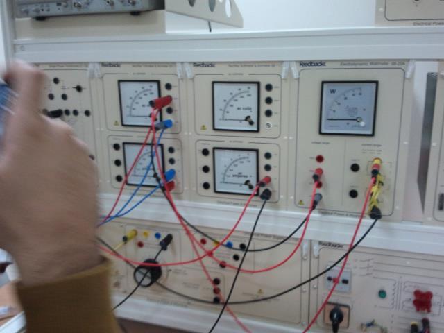
4 2 Experiment Set-up We connect the circuit as shown in the figures:- 2.1 Open Circuit Test Figure 2: This is how we setup the circuit for open circuit test 2.2 Short Circuit Test 3
5 Figure 3: This is how we setup the circuit for short circuit test 3 List of Equipment used Power Training Module. Wires. Wattmeter. Voltmeter. Ammeter. High power supply. 4
, Its presence at the secondary coil can be assumed as open circuit.")
6 4 Procedure 4.1 Open Circuit Test Connect the circuit as shown in the figure below. Figure 4: Since the Voltmeter has approximately infinite resistance (High Resistance), Its presence at the secondary coil can be assumed as open circuit. Calculate cosθ, the angle θ, Ic and Im using equations given below. Now that Ic and Im have been calculated, we can find the value for Core loss Resistance and Magnetizing reactance Xm. Now we can draw a equivalent circuit for the transformer. 5
7 4.2 Short Circuit Test Connect the circuit as shown in the figure below. Figure 5: Since the Ammeter has approximately zero resistance, Its presence at the secondary coil can be assumed as short circuit. Calculate X1 and R1 using equations given below. Now we can draw a more accurate equivalent circuit for the transformer. 6
8 5 Results and Discussions At the end of the lab we got the following results:- 5.1 Open Circuit Test Results Figure 6: As we can see, the voltage in primary side of the transformer is 230 V and current is 0.03A. which is what we supplied through the High power supply. The power produced at the output secondary coil is about 2.5W and the voltage is 250V. 7

9 Figure 7: This is the equivalent circuit we get after doing calculations given below 8

10 9


11 5.2 Short Circuit Test Results Figure 8: After Short circuiting the secondary side of the transformer, we provided 20V, 0.48A current, 3.75W power to the primary side of the transformer we got 0.43A of current going in the secondary side of the transformer. The core losses were calculated to be

12 11
13 6 Conclusion Short circuit test is used for finding out Core losses and open circuit test is used for finding out reactance Xm and Resistance Rc. Both, short circuit test and open circuit test should be performed in order to get the accurate equivalent circuit for the transformer. Core losses include Hysteresis losses and Eddy current losses. Hysteresis Loses are those loses, which are due to the energy lost in continuously change the direction of rotation of electrons in the core. In other words, continuously aligning and re-aligning atoms of core to make them in sync with changing magnetic field causes loss in energy. Eddy Current losses are losses due to presence of unwanted current in the core. The core is made up of metal, usually iron. When a changing magnetic field is applied in the primary side, a current is induced in metallic core. This Current in turn then produces another magnetic field which interacts with the present flux. 7 Team Dynamics Part and Member Weight Grade Muhammad Obaidullah Ali Raza Abdulla Hamoud Abstract 10% 33.3% 33.3% 33.3% Introduction 15% 33.3% 33.3% 33.3% Procedure Part 1 15% 33.3% 33.3% 33.3% Procedure Part 2 15% 33.3% 33.3% 33.3% Results Part 1 15% 33.3% 33.3% 33.3% Results Part 2 15% 33.3% 33.3% 33.3% Conclusion 15% 33.3% 33.3% 33.3% Total 100% 33.3% 33.3% 33.3% References [1] The online electrical engineering study site. Equivalent Circuit of Transformer referred to Primary and Secondary [Electronic] Available: equivalent-circuit-of-transformer-referred-to-primary-and-secondary/ [5 June 2013]. [2] Bulletin B Transformer Insulation Options Page 1 of 6 [Electronic]. Available: B TransformerOptionsforFireSensitiveLocations.pdf September 2006 [4 June 2013]. [3] Fundamentals of Power Engineering Lab 6: Transformers in parallel and 3-phase transformers Page 1 of 8 [Electronic]. Available: %20-%20transformers%20in%20parallel%20and%203-phase%20transformers.pdf Spring 2008 [5 June 2013]. 12
Table of Contents. Table of Figures. Table of Tables
 Abstract The aim of this report is to investigate and test a transformer and check if it is good to use by doing the following tests continuity test, insulation test, polarity test, open circuit test,
EQUIVALENT CIRCUIT OF A SINGLE-PHASE TRANSFORMER
 Electrical Machines Lab Experiment-No. One Date: 15-11-2016 EQUIVALENT CIRCUIT OF A SINGLE-PHASE TRANSFORMER Aim: The determination of electrical equivalent circuit parameters of a single phase power transformer
Transformers. Department of Physics & Astronomy Texas Christian University, Fort Worth, TX. April 23, 2013
 Transformers Department of Physics & Astronomy Texas Christian University, Fort Worth, TX April 23, 2013 1 Introduction In the early nineteenth century, Hans Christian Øersted discovered that a magnetic
EE 448 Fall Lab Experiment No. 3 04/04/2008. Transformer Experiment
 EE 8 Laboratory Experiment 3 EE 8 Fall 2008 Lab Experiment No. 3 0/0/2008 1 I. INTRODUCTION OBJECTIVES: EE 8 Laboratory Experiment 3 1. To learn how real world transformers operate under ideal conditions.
Chapter 2-1 Transformers
 Principles of Electric Machines and Power Electronics Chapter 2-1 Transformers Third Edition P. C. Sen Transformer application 1: power transmission Ideal Transformer Assumptions: 1. Negligible winding
Transformers. ELG3311: Habash,
 Transformers A transformer is a device that changes AC electric power at one voltage level to AC electric power at another voltage level through the action of magnetic field. t consists of two or more
Transformer & Induction M/C
 UNIT- 2 SINGLE-PHASE TRANSFORMERS 1. Draw equivalent circuit of a single phase transformer referring the primary side quantities to secondary and explain? (July/Aug - 2012) (Dec 2012) (June/July 2014)
TRANSFORMER THEORY. Mutual Induction
 Transformers Transformers are used extensively for AC power transmissions and for various control and indication circuits. Knowledge of the basic theory of how these components operate is necessary to
Transformers. gpmacademics.weebly.com
 TRANSFORMERS Syllabus: Principles of operation, Constructional Details, Losses and efficiency, Regulation of Transformer, Testing: OC & SC test. TRANSFORMER: It is a static device which transfers electric
1 K Hinds 2012 TRANSFORMERS
 1 K Hinds 2012 TRANSFORMERS A transformer changes electrical energy of a given voltage into electrical energy at a different voltage level. It consists of two coils which are not electrically connected,
CHAPTER 2. Transformers. Dr Gamal Sowilam
 CHAPTER Transformers Dr Gamal Sowilam Introduction A transformer is a static machine. It is not an energy conversion device, it is indispensable in many energy conversion systems. A transformer essentially
UNIVERSITY OF TECHNOLOGY By: Fadhil A. Hasan ELECTRICAL MACHINES
 UNIVERSITY OF TECHNOLOGY DEPARTMENT OF ELECTRICAL ENGINEERING Year: Second 2016-2017 By: Fadhil A. Hasan ELECTRICAL MACHINES І Module-II: AC Transformers o Single phase transformers o Three-phase transformers
EEE3441 Electrical Machines Department of Electrical Engineering. Lecture. Basic Operating Principles of Transformers
 Department of Electrical Engineering Lecture Basic Operating Principles of Transformers In this Lecture Basic operating principles of following transformers are introduced Single-phase Transformers Three-phase
Experiment 6. Electromagnetic Induction and transformers
 Experiment 6. Electromagnetic Induction and transformers 1. Purpose Confirm the principle of electromagnetic induction and transformers. 2. Principle The PASCO scientific SF-8616 Basic Coils Set and SF-8617
Engineering Science OUTCOME 4 - TUTORIAL 3 CONTENTS. 1. Transformers
 Unit : Unit code: QCF Level: 4 Credit value: 5 SYLLABUS Engineering Science L/60/404 OUTCOME 4 - TUTOIAL 3 Be able to apply single phase AC theory to solve electrical and electronic engineering problems
Lab #5 ENG RC Circuits
 Name:. Lab #5 ENG 220-001 Date: Learning objectives of this experiment is that students will be able to: Measure the effects of frequency upon an RC circuit Calculate and understand circuit current, impedance,
1. THREE-PHASE TRANSFORMER. SHORT CIRCUIT TEST
 1. THREE-PHASE TRANSFORMER. SHORT CIRCUIT TEST 1.1 INTRODUCTION. DESCRIPTION OF THE EXPERIMENT The short-circuit test consists of measuring the input quantities of the transformer when its secondary winding
VOLTECHNOTES. Transformer Basics VPN /1
 Transformer Basics VPN 104-039/1 TRANSFORMER BASICS Introduction Transformer design and test are sometimes viewed as an art rather than a science. Transformers are imperfect devices, and there will be
EE 350: Electric Machinery Fundamentals
 EE 350: Electric Machinery Fundamentals Lecture Schedule See Time Table Course Type, Semester Fundamental Engineering, Fifth Credit Hours Three + One Pre-requisite Physics Instructor Dr. Muhammad Asghar
Outcomes from this session
 Outcomes from this session At the end of this session you should be able to Understand what is meant by the term losses. Iron Losses There are three types of iron losses Eddy current losses Hysteresis
Single-Phase Transformation Review
 Single-Phase Transformation Review S T U D E N T M A N U A L March 2, 2005 2 STUDENT TRAINING MANUAL Prerequisites: None Objectives: Given the Construction Standards manual and a formula sheet, you will
Electrical Machines (EE-343) For TE (ELECTRICAL)
 For TE (ELECTRICAL)") PRACTICALWORKBOOK Electrical Machines (EE-343) For TE (ELECTRICAL) Name: Roll Number: Year: Batch: Section: Semester: Department: N.E.D University of Engineering &Technology, Karachi Electrical Machines
PRACTICALWORKBOOK Electrical Machines (EE-343) For TE (ELECTRICAL) Name: Roll Number: Year: Batch: Section: Semester: Department: N.E.D University of Engineering &Technology, Karachi Electrical Machines
Electrical Theory 2 Lessons for Fall Semester:
 Electrical Theory 2 Lessons for Fall Semester: Lesson 1 Magnetism Lesson 2 Introduction to AC Theory Lesson 3 Lesson 4 Capacitance and Capacitive Reactance Lesson 5 Impedance and AC Circuits Lesson 6 AC
TRANSFORMERS PART A. 2. What is the turns ratio and transformer ratio of transformer? Turns ratio = N2/ N1 Transformer = E2/E1 = I1/ I2 =K
 UNIT II TRANSFORMERS PART A 1. Define a transformer? A transformer is a static device which changes the alternating voltage from one level to another. 2. What is the turns ratio and transformer ratio of
ECE 241L Fundamentals of Electrical Engineering. Experiment 8 A-C Transformer, Magnetization & Hysteresis
 ECE 241L Fundamentals of Electrical Engineering Experiment 8 A-C Transformer, Magnetization & Hysteresis A. Objectives: I. Measure leakage inductance and resistance loss II. Measure magnetization inductance
M.B.S PUBLIC SCHOOL PHYSICS INVESTIGATORY PROJECT TRANSFORMERS BY:- AYASHKANT MISHRA. STD:-XII SEC:-A ROLL NO :
 M.B.S PUBLIC SCHOOL PHYSICS INVESTIGATORY PROJECT TRANSFORMERS BY:- AYASHKANT MISHRA. STD:-XII SEC:-A ROLL NO :- 2014-15 M.B.S Public school Department of physics CERTIFICATE This is to certify that Ayashkant
Unit 3 Magnetism...21 Introduction The Natural Magnet Magnetic Polarities Magnetic Compass...21
 Chapter 1 Electrical Fundamentals Unit 1 Matter...3 Introduction...3 1.1 Matter...3 1.2 Atomic Theory...3 1.3 Law of Electrical Charges...4 1.4 Law of Atomic Charges...4 Negative Atomic Charge...4 Positive
Exercise 10. Transformers EXERCISE OBJECTIVE DISCUSSION OUTLINE DISCUSSION. Introduction to transformers
 Exercise 10 Transformers EXERCISE OBJECTIVE When you have completed this exercise, you will be familiar with the basic operating principles of transformers, as well as with the different ratios of transformers:
Preface...x Chapter 1 Electrical Fundamentals
 Preface...x Chapter 1 Electrical Fundamentals Unit 1 Matter...3 Introduction...3 1.1 Matter...3 1.2 Atomic Theory...3 1.3 Law of Electrical Charges...4 1.4 Law of Atomic Charges...5 Negative Atomic Charge...5
Experiment 3 Single Phase Transformer (II)
") Objectives To determine the polarity of single phase transformer windings. To determine the internal resistance of single phase transformer windings. To determine the efficiency and voltage regulation
Objectives To determine the polarity of single phase transformer windings. To determine the internal resistance of single phase transformer windings. To determine the efficiency and voltage regulation
ECE 321 Experiment No: 4 Energy Systems Lab 1 Fall 2009 TRANSFORMERS-1
 TRANSFORMER: EXPERIMENT NO 4 TRANSFORMERS-1 The transformer, which is made up of two or more coils or windings linked magnetically, with or without a core to shape and enhance the magnetic flux, is used
No Brain Too Small PHYSICS
 ELECTRICITY: AC QUESTIONS No Brain Too Small PHYSICS MEASURING IRON IN SAND (2016;3) Vivienne wants to measure the amount of iron in ironsand mixtures collected from different beaches. The diagram below
Unit FE-5 Foundation Electricity: Electrical Machines
 Unit FE-5 Foundation Electricity: Electrical Machines What this unit is about Power networks consist of large number of interconnected hardware. This unit deals specifically with two types of hardware:
ELECTRICAL MEASUREMENTS
 R10 Set No: 1 1. a) Derive the expression for torque equation for a moving iron attraction type instrument and comment up on the nature of scale [8] b) Define the terms current sensitivity, voltage sensitivity
Walchand Institute of Technology. Basic Electrical and Electronics Engineering. Transformer
 Walchand Institute of Technology Basic Electrical and Electronics Engineering Transformer 1. What is transformer? explain working principle of transformer. Electrical power transformer is a static device
TRANSFORMERS INTRODUCTION
 Tyco Electronics Corporation Crompton Instruments 1610 Cobb International Parkway, Unit #4 Kennesaw, GA 30152 Tel. 770-425-8903 Fax. 770-423-7194 TRANSFORMERS INTRODUCTION A transformer is a device that
Module 7. Transformer. Version 2 EE IIT, Kharagpur
 Module 7 Transformer Lesson 28 Problem solving on Transformers Contents 28 Problem solving on Transformer (Lesson-28) 4 28.1 Introduction. 4 28.2 Problems on 2 winding single phase transformers. 4 28.3
Trade of Electrician. The Transformer
 Trade of Electrician Standards Based Apprenticeship The Transformer Phase 2 Module No. 2.1 Unit No. 2.1.10 COURSE NOTES Created by Gerry Ryan - Galway TC Revision 1 April 2000 by Gerry Ryan - Galway TC
Experiment No. Experiments for First Year Electrical Engg Lab
 Experiment No im: To determine Regulation and Efficiency of a single phase transformer using open circuit (O.C.) and short circuit (S.C.) tests pparatus: - Single phase transformer Single phase dimmer
SHRI RAMSWAROOP MEMORIAL COLLEGE OF ENGG. & MANAGEMENT B.Tech. [SEM I (EE, EN, EC, CE)] QUIZ TEST-3 (Session: ) Time: 1 Hour ELECTRICAL ENGINEE
![SHRI RAMSWAROOP MEMORIAL COLLEGE OF ENGG. & MANAGEMENT B.Tech. [SEM I (EE, EN, EC, CE)] QUIZ TEST-3 (Session: ) Time: 1 Hour ELECTRICAL ENGINEE](/thumbs/94/118213481.jpg "SHRI RAMSWAROOP MEMORIAL COLLEGE OF ENGG. & MANAGEMENT B.Tech. [SEM I (EE, EN, EC, CE)] QUIZ TEST-3 (Session: ) Time: 1 Hour ELECTRICAL ENGINEE") SHRI RAMSWAROOP MEMORIAL COLLEGE OF ENGG. & MANAGEMENT B.Tech. [SEM I (EE, EN, EC, CE)] QUIZ TEST-3 (Session: 2014-15) Time: 1 Hour ELECTRICAL ENGINEERING Max. Marks: 30 (NEE-101) Roll No. Academic/26
SHRI RAMSWAROOP MEMORIAL COLLEGE OF ENGG. & MANAGEMENT B.Tech. [SEM I (EE, EN, EC, CE)] QUIZ TEST-3 (Session: 2014-15) Time: 1 Hour ELECTRICAL ENGINEERING Max. Marks: 30 (NEE-101) Roll No. Academic/26
AUTO-TRANSFORMER. This is having only one winding; part of this winding is common to both primary and secondary.
 AUTO-TRANSFORMER This is having only one winding; part of this winding is common to both primary and secondary. In 2-winding transformer both primary and secondary windings are electrically isolated, but
Chapter 33. Alternating Current Circuits
 Chapter 33 Alternating Current Circuits Alternating Current Circuits Electrical appliances in the house use alternating current (AC) circuits. If an AC source applies an alternating voltage to a series
ISSN: X Impact factor: (Volume 3, Issue 6) Available online at Modeling and Analysis of Transformer
 Available online at Modeling and Analysis of Transformer") ISSN: 2454-132X Impact factor: 4.295 (Volume 3, Issue 6) Available online at www.ijariit.com Modeling and Analysis of Transformer Divyapradeepa.T Department of Electrical and Electronics, Rajalakshmi Engineering
ISSN: 2454-132X Impact factor: 4.295 (Volume 3, Issue 6) Available online at www.ijariit.com Modeling and Analysis of Transformer Divyapradeepa.T Department of Electrical and Electronics, Rajalakshmi Engineering
Module 1. Introduction. Version 2 EE IIT, Kharagpur
 Module 1 Introduction Lesson 1 Introducing the Course on Basic Electrical Contents 1 Introducing the course (Lesson-1) 4 Introduction... 4 Module-1 Introduction... 4 Module-2 D.C. circuits.. 4 Module-3
EFFICIENCY APPLICATION NOTES. Power Purifier - IPP#15. General. Why is it Important to Consider Efficiency?
 APPLICATION NOTES EFFICIENCY Power Purifier - IPP#15 Ipefcya2 24Nov1998 General The efficiency of a transformer is very important in terms of energy lost. Efficiency deals with the power losses of a transformer.
1. If the flux associated with a coil varies at the rate of 1 weber/min,the induced emf is
 1. f the flux associated with a coil varies at the rate of 1 weber/min,the induced emf is 1 1. 1V 2. V 60 3. 60V 4. Zero 2. Lenz s law is the consequence of the law of conservation of 1. Charge 2. Mass
University of North Carolina-Charlotte Department of Electrical and Computer Engineering ECGR 4143/5195 Electrical Machinery Fall 2009
 University of North Carolina-Charlotte Department of Electrical and Computer Engineering ECGR 4143/5195 Electrical Machinery Fall 2009 Problem Set 3 Due: Monday September 28 Recommended Reading: Fitzgerald
NATIONAL SENIOR CERTIFICATE GRADE 12
 NATIONAL SENIOR CERTIFICATE GRADE 12 ELECTRICAL TECHNOLOGY NOVEMBER 2008 MEMORANDUM This memorandum consists of 12 pages. Electrical Technology 2 DoE/November 2008 QUESTION 1: TECHNOLOGY, SOCIETY AND THE
Module 7. Transformer. Version 2 EE IIT, Kharagpur
 Module 7 Transformer Lesson 3 Ideal Transformer Contents 3 Ideal Transformer (Lesson: 3) 4 3. Goals of the lesson 4 3. Introduction.. 5 3.. Principle of operation.. 5 3.3 Ideal Transformer.. 6 3.3. Core
Code No: RR Set No. 1
 Code No: RR310202 Set No. 1 III B.Tech I Semester Regular Examinations, November 2006 ELECTRICAL MEASUREMENTS (Electrical & Electronic Engineering) Time: 3 hours Max Marks: 80 Answer any FIVE Questions
Chapter 7. Copyright The McGraw-Hill Companies, Inc. Permission required for reproduction or display.
 Chapter 7 Copyright The McGraw-Hill Companies, Inc. Permission required for reproduction or display. Learning Objectives 1. Understand the meaning of instantaneous and average power, master AC power notation,
INSTITUTE OF AERONAUTICAL ENGINEERING (Autonomous) Dundigal, Hyderabad
 Dundigal, Hyderabad") INSTITUTE OF AERONAUTICAL ENGINEERING (Autonomous) Dundigal, Hyderabad - 00 0 ELECTRICAL AND ELECTRONICS ENGINEERING QUESTION BANK Course Name Course Code Class Branch : ELECRICAL MACHINES - II : A0 :
INSTITUTE OF AERONAUTICAL ENGINEERING (Autonomous) Dundigal, Hyderabad - 00 0 ELECTRICAL AND ELECTRONICS ENGINEERING QUESTION BANK Course Name Course Code Class Branch : ELECRICAL MACHINES - II : A0 :
SHRI RAMSWAROOP MEMORIAL COLLEGE OF ENGG. & MANAGEMENT
 SHRI RAMSWAROOP MEMORIAL COLLEGE OF ENGG. & MANAGEMENT B.Tech. [SEM I (CE,EC,EE,EN)] QUIZ TEST-3 (Session: 2012-13) Time: 1 Hour ELECTRICAL ENGINEERING Max. Marks: 30 (EEE-101) Roll No. Academic/26 Refer/WI/ACAD/18
(a) (i) Is the transformer in the diagram being used as a step-up transformer or as a step-down transformer? ) in the box next to your answer. ...
 (i) Is the transformer in the diagram being used as a step-up transformer or as a step-down transformer? ) in the box next to your answer. ...") Q1.The diagram shows a transformer. (a) (i) Is the transformer in the diagram being used as a step-up transformer or as a step-down transformer? Put a tick ( ) in the box next to your answer. a step-up
Q1.The diagram shows a transformer. (a) (i) Is the transformer in the diagram being used as a step-up transformer or as a step-down transformer? Put a tick ( ) in the box next to your answer. a step-up
2. Meter Measurements and Loading Effects in Resistance Circuits
 2. Meter Measurements and Loading Effects in Resistance Circuits 2.1. Purpose 1. To measure and predict the affects of multimeter(s) on a circuit when measuring electrical quantities. 2. To make use of
Transformers. Question Paper. Save My Exams! The Home of Revision. Subject Physics (4403) Exam Board. Keeping Things Moving. Page 1.
 Exam Board. Keeping Things Moving. Page 1.") Transformers Question Paper Level IGCSE Subject Physics (4403) Exam Board AQA Unit P3 Topic Keeping Things Moving Sub-Topic Transformers Booklet Question Paper Time Allowed: 58 minutes Score: /58 Percentage:
Transformers Question Paper Level IGCSE Subject Physics (4403) Exam Board AQA Unit P3 Topic Keeping Things Moving Sub-Topic Transformers Booklet Question Paper Time Allowed: 58 minutes Score: /58 Percentage:
SECTION 3 BASIC AUTOMATIC CONTROLS UNIT 12 BASIC ELECTRICITY AND MAGNETISM. Unit Objectives. Unit Objectives 2/29/2012
 SECTION 3 BASIC AUTOMATIC CONTROLS UNIT 12 BASIC ELECTRICITY AND MAGNETISM Unit Objectives Describe the structure of an atom. Identify atoms with a positive charge and atoms with a negative charge. Explain
INSTITUTE OF AERONAUTICAL ENGINEERING (Autonomous) Dundigal, Hyderabad ELECTRICAL AND ELECTRONICS ENGINEERING
 Dundigal, Hyderabad ELECTRICAL AND ELECTRONICS ENGINEERING") Course Name Course Code Class Branch INSTITUTE OF AERONAUTICAL ENGINEERING (Autonomous) Dundigal, Hyderabad - 500 043 ELECTRICAL AND ELECTRONICS ENGINEERING QUESTION BANK : ELECRICAL MACHINES I : A40212
Course Name Course Code Class Branch INSTITUTE OF AERONAUTICAL ENGINEERING (Autonomous) Dundigal, Hyderabad - 500 043 ELECTRICAL AND ELECTRONICS ENGINEERING QUESTION BANK : ELECRICAL MACHINES I : A40212
APPLICATION NOTE - 018
 APPLICATION NOTE - 018 Power Transformers Background Power Transformers are used within an AC power distribution systems to increase or decrease the operating voltage to achieve the optimum transmission
ESO 210 Introduction to Electrical Engineering
 ESO 210 Introduction to Electrical Engineering Lecture-14 Three Phase AC Circuits 2 THE -CONNECTED GENERATOR If we rearrange the coils of the generator as shown in Fig. below the system is referred to
Generator Advanced Concepts
 Generator Advanced Concepts Common Topics, The Practical Side Machine Output Voltage Equation Pitch Harmonics Circulating Currents when Paralleling Reactances and Time Constants Three Generator Curves
Unit Transformers
 Unit 11.08 Transformers Prepared in Dec 1998 Second editing in march 2000 Learning objectives At the end of this unit you should be able to : 1. describe the structure and principle of operation of a basic
Figure 1. Why is iron a suitable material for the core of a transformer?
 INDUCED POTENTIAL, TRANSFORMERS: NAT GRID Q1. Figure 1 shows the construction of a simple transformer. Figure 1 Why is iron a suitable material for the core of a transformer? Tick one box. It is a metal.
The topics in this unit are:
 The topics in this unit are: 1 Static electricity 2 Repulsion and attraction 3 Electric circuits 4 Circuit symbols 5 Currents 6 Resistance 7 Thermistors and light dependent resistors 8 Series circuits
ECG 741 Power Distribution Transformers. Y. Baghzouz Spring 2014
 ECG 741 Power Distribution Transformers Y. Baghzouz Spring 2014 Preliminary Considerations A transformer is a device that converts one AC voltage to another AC voltage at the same frequency. The windings
Reg. No. : BASIC ELECTRICAL TECHNOLOGY (ELE 101)
") Department of Electrical and Electronics Engineering Reg. No. : MNIPL INSTITUTE OF TECHNOLOGY, MNIPL ( Constituent Institute of Manipal University, Manipal) FIRST SEMESTER B.E. DEGREE MKEUP EXMINTION (REVISED
Department of Electrical and Electronics Engineering Reg. No. : MNIPL INSTITUTE OF TECHNOLOGY, MNIPL ( Constituent Institute of Manipal University, Manipal) FIRST SEMESTER B.E. DEGREE MKEUP EXMINTION (REVISED
Chapter 33. Alternating Current Circuits
 Chapter 33 Alternating Current Circuits C HAP T E O UTLI N E 33 1 AC Sources 33 2 esistors in an AC Circuit 33 3 Inductors in an AC Circuit 33 4 Capacitors in an AC Circuit 33 5 The L Series Circuit 33
cos sin XqIq cos sin V X Consider a simple case ignoring R a and X l d axis q axis V q I q V d I d Approximately, the second item can be ignored:
 Consider a simple case ignoring R a and X l E cos XdId I d E X d cos sin XqIq E E jxdid jxqi q jxdid q jx I d axis q axis I q q d q q I q sin X q d P3 3 I a cos I d I cos abdei cos I sin a q d E Xd Xq
PHYS 1442 Section 004 Lecture #15
 PHYS 1442 Section 004 Lecture #15 Monday March 17, 2014 Dr. Andrew Brandt Chapter 21 Generator Transformer Inductance 3/17/2014 1 PHYS 1442-004, Dr. Andrew Brandt Announcements HW8 on Ch 21-22 will be
Rony Parvej s EEE. Lecture 3 & 4: Transformer. Update: 30 April, fecabook.com/ronyiut
 Rony Parvej s EEE Lecture 3 & 4: Transformer Update: 30 April, 2015 fecabook.com/ronyiut 1 2 TRANSFORMER What is the voltage at secondary side of a transformer having a turn ratio of 1:10 if 440V dc is
11. AC-resistances of capacitor and inductors: Reactances.
 11. AC-resistances of capacitor and inductors: Reactances. Purpose: To study the behavior of the AC voltage signals across elements in a simple series connection of a resistor with an inductor and with
Laminate Transformer Testing
 1. Introduction: Laminate transformers are mostly used as line frequency, low frequency and low/high voltage step-up, step-down transformers. Two coils are wound over a core such that they are magnetically
Lesson Plan. Week Theory Practical Lecture Day. Topic (including assignment / test) Day. Thevenin s theorem, Norton s theorem
 Day. Thevenin s theorem, Norton s theorem") Name of the faculty: GYANENDRA KUMAR YADAV Discipline: APPLIED SCIENCE(C.S.E,E.E.ECE) Year : 1st Subject: FEEE Lesson Plan Lesson Plan Duration: 31 weeks (from July, 2018 to April, 2019) Week Theory Practical
Name of the faculty: GYANENDRA KUMAR YADAV Discipline: APPLIED SCIENCE(C.S.E,E.E.ECE) Year : 1st Subject: FEEE Lesson Plan Lesson Plan Duration: 31 weeks (from July, 2018 to April, 2019) Week Theory Practical
Basic Electrical Engineering
 Basic Electrical Engineering S.N. Singh Basic Electrical Engineering S.N. Singh Professor Department of Electrical Engineering Indian Institute of Technology Kanpur PHI Learning Private Limited New Delhi-110001
EE2022 Electrical Energy Systems
 EE0 Electrical Energy Systems Lecture : Transformer and Per Unit Analysis 7-0-0 Panida Jirutitijaroen Department of Electrical and Computer Engineering /9/0 EE0: Transformer and Per Unit Analysis by P.
CHAPTER 6: ALTERNATING CURRENT
 CHAPTER 6: ALTERNATING CURRENT PSPM II 2005/2006 NO. 12(C) 12. (c) An ac generator with rms voltage 240 V is connected to a RC circuit. The rms current in the circuit is 1.5 A and leads the voltage by
n = V1 n = V2 110 = So the output current will be times the input current = = 123 Amp (ANS)
") Unit 4 Physics 016 14. Transformers and transmission Page 1 of 6 Checkpoints Chapter 14 and transmission. Question 556 Transformers This is a step down transformer, because the output voltage is less than
Unit 4 Physics 016 14. Transformers and transmission Page 1 of 6 Checkpoints Chapter 14 and transmission. Question 556 Transformers This is a step down transformer, because the output voltage is less than
1. SQUIRREL CAGE AC MOTOR. NO LOAD TEST
 1. SQUIRREL CAGE AC MOTOR. NO LOAD TEST 1.1 INTRODUCTION. DESCRIPTION OF THE EXPERIMENT The three-phase induction motor carries a three-phase winding on its stator. The rotor is either a wound type or
The power transformer
 ELEC0014 - Introduction to power and energy systems The power transformer Thierry Van Cutsem t.vancutsem@ulg.ac.be www.montefiore.ulg.ac.be/~vct November 2017 1 / 35 Power transformers are used: to transmit
UNIT-04 ELECTROMAGNETIC INDUCTION & ALTERNATING CURRNT
 UNIT-04 ELECTROMAGNETIC INDUCTION & ALTERNATING CURRNT.MARK QUESTIONS:. What is the magnitude of the induced current in the circular loop-a B C D of radius r, if the straight wire PQ carries a steady current
EE 340 Power Transformers
 EE 340 Power Transformers Preliminary considerations A transformer is a device that converts one AC voltage to another AC voltage at the same frequency. It consists of one or more coil(s) of wire wrapped
TRANSFORMER OPERATION
 Chapter 3 TRANSFORMER OPERATION 1 A transformer is a static device (no moving parts) used to transfer energy from one AC circuit to another. This transfer of energy may involve an increase or decrease
CH 1. Large coil. Small coil. red. Function generator GND CH 2. black GND
 Experiment 6 Electromagnetic Induction "Concepts without factual content are empty; sense data without concepts are blind... The understanding cannot see. The senses cannot think. By their union only can
VOLTECHNOTES. Turns Ratio iss 4 Page 1 of 7
 VOLTECHNOTES Turns Ratio 104-113 iss 4 Page 1 of 7 Introduction Transformers are used in a wide array of electrical or electronic applications, providing functions that range from isolation and stepping
Introduction : Design detailed: DC Machines Calculation of Armature main Dimensions and flux for pole. Design of Armature Winding & Core.
 Introduction : Design detailed: DC Machines Calculation of Armature main Dimensions and flux for pole. Design of Armature Winding & Core. Design of Shunt Field & Series Field Windings. Design detailed:
ELECTRICAL TECHNOLOGY EET 103/4
 ELECTRICAL TECHNOLOGY EET 103/4 Define and analyze the rincile of transformer, its arameters and structure. Describe and analyze Ideal transformer, equivalent circuit, and hasor diagram Calculate and justify
ELECTRICAL ENGINEERING ESE TOPIC WISE OBJECTIVE SOLVED PAPER-II
 ELECTRICAL ENGINEERING ESE TOPIC WISE OBJECTIVE SOLVED PAPER-II From (1992 2017) Office : F-126, (Lower Basement), Katwaria Sarai, New Delhi-110016 Phone : 011-26522064 Mobile : 8130909220, 9711853908
3. What is hysteresis loss? Also mention a method to minimize the loss. (N-11, N-12)
") DHANALAKSHMI COLLEGE OF ENGINEERING, CHENNAI DEPARTMENT OF ELECTRICAL AND ELECTRONICS ENGINEERING EE 6401 ELECTRICAL MACHINES I UNIT I : MAGNETIC CIRCUITS AND MAGNETIC MATERIALS Part A (2 Marks) 1. List
DHANALAKSHMI COLLEGE OF ENGINEERING, CHENNAI DEPARTMENT OF ELECTRICAL AND ELECTRONICS ENGINEERING EE 6401 ELECTRICAL MACHINES I UNIT I : MAGNETIC CIRCUITS AND MAGNETIC MATERIALS Part A (2 Marks) 1. List
REV NO EXPERIMENT NO 1 AIM: To perform open and short circuit tests on 1-phase transformer and to calculate efficiency. Apparatus required:
 KARNAL INSTITUTE OF TECHNOLOGY & MANAGEMENT KUNJPURA, KARNAL LAB MANUAL OF ------- SUBJECT CODE DATE OF ISSUE: SEMESTER: BRANCH: REV NO EXPERIMENT NO 1 AIM: To perform open and short circuit tests on 1-phase
1. (a) Determine the value of Resistance R and current in each branch when the total current taken by the curcuit in figure 1a is 6 Amps.
 Determine the value of Resistance R and current in each branch when the total current taken by the curcuit in figure 1a is 6 Amps.") Code No: 07A3EC01 Set No. 1 II B.Tech I Semester Regular Examinations, November 2008 ELECTRICAL AND ELECTRONICS ENGINEERING ( Common to Civil Engineering, Mechanical Engineering, Mechatronics, Production
Code No: 07A3EC01 Set No. 1 II B.Tech I Semester Regular Examinations, November 2008 ELECTRICAL AND ELECTRONICS ENGINEERING ( Common to Civil Engineering, Mechanical Engineering, Mechatronics, Production
MEHRAN UNIVERSITY OF ENGINEERING & TECHNOLOGY, JAMSHORO
 DEPARTMENT OF MEHRAN UNIVERSITY OF ENGINEERING & TECHNOLOGY, JAMSHORO Name Roll No. Subject Teacher MEHRAN UNIVERSITY OF ENGINEERING & TECHNOLOGY, JAMSHORO 1 Name:. Roll No: Score: Signature of Lab Tutor:
Project Report Designing Wein-Bridge Oscillator
 Abu Dhabi University EEN 360 - Electronic Devices and Circuits II Project Report Designing Wein-Bridge Oscillator Author: Muhammad Obaidullah 03033 Bilal Arshad 0929 Supervisor: Dr. Riad Kanan Section
Chapter 2: Transformers
 Chapter 2: Transformers 2-1. The secondary winding of a transformer has a terminal voltage of v s (t) = 282.8 sin 377t V. The turns ratio of the transformer is 100:200 (a = 0.50). If the secondary current
Dhanalakshmi Srinivasan Institute of Technology, Samayapuram, Trichy. Cycle 2 EE6512 Electrical Machines II Lab Manual
 Cycle 2 EE652 Electrical Machines II Lab Manual CIRCUIT DIAGRAM FOR SLIP TEST 80V DC SUPPLY 350Ω, 2 A 3 Point Starter L F A NAME PLATE DETAILS: 3Ф alternator DC shunt motor FUSE RATING: Volts: Volts: 25%
MAHARASHTRA STATE BOARD OF TECHNICAL EDUCATION
 Important Instructions to examiners: 1) The answers should be examined by key words and not as word-to-word as given in the model answer scheme. 2) The model answer and the answer written by candidate
VALLIAMMAI ENGINEERING COLLEGE
 VALLIAMMAI ENGINEERING COLLEGE SRM Nagar, Kattankulathur 603 203 DEPARTMENT OF ELECTRONICS AND INSTRUMENTATION ENGINEERING QUESTION BANK IV SEMESTER EI6402 ELECTRICAL MACHINES Regulation 2013 Academic
Transformer Waveforms
 OBJECTIVE EXPERIMENT Transformer Waveforms Steady-State Testing and Performance of Single-Phase Transformers Waveforms The voltage regulation and efficiency of a distribution system are affected by the
RC circuit. Recall the series RC circuit.
 RC circuit Recall the series RC circuit. If C is discharged and then a constant voltage V is suddenly applied, the charge on, and voltage across, C is initially zero. The charge ultimately reaches the
Transformers. Dr. Gamal Sowilam
 Transformers Dr. Gamal Sowilam OBJECTIVES Become familiar with the flux linkages that exist between the coils of a transformer and how the voltages across the primary and secondary are established. Understand
TUNED AMPLIFIERS 5.1 Introduction: Coil Losses:
 TUNED AMPLIFIERS 5.1 Introduction: To amplify the selective range of frequencies, the resistive load R C is replaced by a tuned circuit. The tuned circuit is capable of amplifying a signal over a narrow