Rony Parvej s EEE. Lecture 3 & 4: Transformer. Update: 30 April, fecabook.com/ronyiut
|
|
|
- Georgia Crawford
- 6 years ago
- Views:
Transcription


1 Rony Parvej s EEE Lecture 3 & 4: Transformer Update: 30 April, 2015 fecabook.com/ronyiut
2 1 2 TRANSFORMER What is the voltage at secondary side of a transformer having a turn ratio of 1:10 if 440V dc is applied at primary? (a) 0 V (b) 4400 V (c) 44 V (d) 4.4 V What would be your comment regarding the size, of a 1 kva. 400 Hz transformer and a 1 kva, 50 Hz transformer? (a) 400 Hz transformer is smaller in size (b) 50 Hz transformer is smaller in size (c) both the transformer are of equal size (d) no comment can be made without seeing the transformer (e) none of the above DPDC-14 MCQ BPDB Draw an equivalent circuit of transformer referred to secondary. DWASA-14 4 Draw the vector diagram of a single phase step down transformer. BPDB-11 A 400 V/100 V, 500 VA single phase transformer has an equivalent impedance of 0.5 NWPGCL-14 5 p.u. If the primary winding impedance is 0.1 ohm,find the secondary winding impedance in ohm both referred to secondary. 6 What are the no load and full load losses of transformer? PGCB-14 7 What are the load and no load losses of a transformer? What is all day efficiency of a transformer? BUET M.Sc Maximum efficiency of a transformer is 98%. It runs at 50% efficiency for 14 hours PGCB-14 and at no load for remaining 10 hours. Find it s all day efficiency. 9 A 30 kva, 2400/240 V, 50 Hz single phase transformer, operating at no load, draws BPDB W at a p.f. of 0.21 lagging. Determine i) the exciting current of the transformer ii) the core loss component of the exciting current and iii) the magnetizing component of the exciting current. 10 A single phase 1000/200 V takes a no load current of 3A at 0.2 power factor lagging. EGCB-2014 Calculate the primary current and power factor when secondary current is 280 A at power factor 0.8 lagging. 11 A single phase transformer with a ratio of 100/200 V takes a no-load current of 3A at 0.2 power factor lagging. If the secondary supplies a current of 280 A at a p.f. of 0.8 lagging, estimate the current taken by the primary. BPDB-2015, EGCB The equivalent circuit impedances of a 20kVA, 8000/240V, 60Hz transformer are to be determined. The open circuit test and the short circuit test were performed on the primary side of the transformer, and the following data were taken: Open circuit test (primary) Short circuit test V OC = 8000 V V SC = 489 V I OC = A I SC = 2.5 A P OC = 400 W P SC = 240 W BPDB-14 (FF) 13 Find the impedance of the approximate equivalent circuit referred to the primary side, and sketch the circuit. [Example 2.2, Chapman 4 th edition] In short circuit test of a transformer in which side supply voltage is applied? (a) Low voltage side (b) High voltage side In short circuit test of single phase transformer, the wattmeter reading roughly gives DPDC MCQ- 14 MCQ
3 14 (a) Copper loss (b)core loss (c) Both (d)none PGCB-14 In open circuit test of transformer power supply is given in MCQ 15 (a) low voltage side (b) high voltage side (c) (d) PGCB-14 Practically in open circuit test of a transformer, the wattmeter measures DPDC MCQ- 16 (a) Copper loss (b) Core loss 14 (c) A slight copper loss (d) both (b) & (c) 17 Why transformer is rated in KVA? What are the instrument transformers? PGCL Write down the conditions of parallel operation of transformers. BUET M.Sc. Unknown Show the direction of the current in primary and polarity of the load initially: PGCB Which of the following is not an example of transformer connection? (a) Open delta - Y (b) (c) (d) MCQ- DWASA Dy1 means- (a) Primary is delta and secondary is star connected and secondary leads primary by 30º (b) Primary is delta and secondary is star connected and primary leads secondary by 30º What do you understand by DY1 (a) High voltage side is leading low voltage side by 30º (b) Low voltage side is leading high voltage side by 30º MCQ EGCB-14 MCQ EGCB In a 3-phase transformer DY1 means- MCQ EGCB-12 UNIT transformer at power generation is used as an- MCQ 24 (a) energy meter (b)step up transformer (c) auxiliary transformer PGCB-14 Why do we ground Y-neutral in D-Y transformer? (i) for flowing zero sequence current MCQ BPDB- 25 (ii) 14 (FF) 26 What are the disadvantages of 3-phase Y-Y connected transformer? How this problem can be solved? 27 A 500KVA, 13200/480 V distribution transformer has four taps 2.5% on its primary winding. What are the voltage ratios of this transformer at each tapings? BUET M.Sc.12 DWASA-14

4 What is the voltage at secondary side of a transformer having a turn ratio of 1:10 if DPDC V dc is applied at primary? (a) 0 V (b) 4400 V (c) 44 V (d) 4.4 V A transformer cannot raise or lower the voltage of a D.C. supply because Faraday's laws of electromagnetic induction are not valid since the rate of change of flux is zero. As transformers require an alternating magnetic flux to operate correctly, transformers cannot therefore be used to transform or supply DC voltages or currents, since the magnetic field must be changing to induce a voltage in the secondary winding. In other words, Transformers DO NOT Operate on DC Voltages. So, the output is zero. Reference: Basic Electrical Engineering U.A. Bakshi What would be your comment regarding the size, of a 1 kva. 400 Hz transformer and a 1 kva, 50 Hz transformer? (a) 400 Hz transformer is smaller in size 2 (b) 50 Hz transformer is smaller in size (c) both the transformer are of equal size (d) no comment can be made without seeing the transformer (e) none of the above MCQ BPDB- 13 Due to some mechanical constraints, generally transformer size is inversely proportional to the operating frequency. Thus 50 hz, transformer will have max. size. The impedance of the transformer is greater for higher frequencies (as X=wL). So for constant voltage to keep same current rating (because for constant kva) we have to reduce the inductance of the winding. And to reduce the inductance we have to reduce the no. of turns in the windings of the transformer. By reducing the no. of turns the size of the transformer will be reduced for higher frequencies. This is a short cut method based on analysis. generally power transformers use lower frequency (50hz) and we know in electronic ckts like oscillators producing very high frqs in range of KHz we use only SMALL trfrs than pwr trfrs... so on analysing we can conclude tat higher frquency transformers have less volume... NOTE: this is only shortcut method, actual reason depends on the FORMULA only for determining the size
5 3 Draw an equivalent circuit of transformer referred to secondary. DWASA-14 Figure: Equivalent transformer circuit referring to the primary Figure: Equivalent transformer circuit referring to the secondary Reference: Electric Machinary Fundamentals - Chapman 4 Draw the vector diagram of a single phase step down transformer. BPDB-11 Figure: vector diagram of a single phase step down (V P >V S ) transformer at lagging power factor.
6 Figure: vector diagram of a single phase step down (V P >V S ) transformer at leading power factor. Figure: vector diagram of a single phase step down (V P >V S ) transformer at unity power factor. : Figure: vector diagram of a single phase step down (V P >V S ) transformer at no load.
7 A 400 V/100 V, 500 VA single phase transformer has an equivalent impedance of p.u. If the primary winding impedance is 0.1 ohm, find the secondary winding impedance in ohm both referred to secondary. p.u এর ম য থ কর র সম য় এট করব NWPGCL-14 6 What are the no load and full load losses of transformer? PGCB-14 No Load Losses: Iron loss: Hysteresis and eddy current loss Very small amount of copper loss also occurs in primary Full Load losses: At full load, Copper loss is largest and a very small amount of eddy current loss is there. 7 What are the load and no load losses of a transformer? What is all day efficiency of a transformer? BUET M.Sc. 13 A transformer has mainly two types of losses, these are, iron losses and copper losses. Iron loss, which is also referred as core loss, consists of hysteresis loss and eddy current loss. These two losses are constant when the transformer is charged. That means the amount of these losses does not depend upon the condition of secondary load of the transformer. In all loading condition, these are fixed. But the copper loss which is also referred as I 2 R loss entirely depends upon load I. A distribution transformer cannot be run with constant load throughout 24 hours. At day peak time it s loading is high, whereas in night lean time its loading may be negligible. So selecting a transformer depending upon its conventional efficiency is not practical and economical, too. As a solution of these problems, the concept of all day efficiency of distribution transformer came into the picture. In this concept, we use the ratio of total energy delivered by the transformer to the total energy fed to the transformer, during a 24 hrs span of time instead of ratio of power output and input of the transformer. Hence, all day efficiency is determined as, total KWh at the secondary of the total KWh at the primary of the transformer for a long specific period preferably 24 hrs. i.e, This is very much useful to judge the performance of a distribution transformer, whose primary is connected to the system forever, but secondary load varies tremendously throughout the day. 8 PGCB-14
8
 the exciting current of the transformer ii) the core loss component of the exciting current and iii) the magnetizing component of")
9 9 A 30 kva, 2400/240 V, 50 Hz single phase transformer, operating at no load, draws 138 W at a p.f. of 0.21 lagging. Determine i) the exciting current of the transformer ii) the core loss component of the exciting current and iii) the magnetizing component of the exciting current. BPDB-13
10 10 A single phase 1000/200 V takes a no load current of 3A at 0.2 power factor lagging. Calculate the primary current and power factor when secondary current is 280 A at power factor 0.8 lagging. EGCB-2014 ১১ ন এর অন র প 11 A single phase transformer with a ratio of 100/200 V takes a no-load current of 3A at 0.2 power factor lagging. If the secondary supplies a current of 280 A at a p.f. of 0.8 lagging, estimate the current taken by the primary. BPDB-2015, EGCB The equivalent circuit impedances of a 20kVA, 8000/240V, 60Hz transformer are to be determined. The open circuit test and the short circuit test were performed on the BPDB-14
11 primary side of the transformer, and the following data were taken: (FF) Open circuit test (primary) Short circuit test V OC = 8000 V V SC = 489 V I OC = A I SC = 2.5 A P OC = 400 W P SC = 240 W Find the impedance of the approximate equivalent circuit referred to the primary side, and sketch the circuit. [Example 2.2, Chapman 4 th edition] In short circuit test of a transformer in which side supply voltage is applied? DPDC MCQ-
12 13 (a) Low voltage side (b) High voltage side 14 Open Circuit Test: The main purpose of this test is to find the iron loss and no load current which are useful in calculating core loss resistance and magnetizing reactance of the transformer. In O.C. test primary winding is connected to a.c. supply, keeping secondary open. Sometimes a voltmeter may be connected across secondary as voltmeter resistance is very high & voltmeter current is negligibly small so that secondary is treated as open circuit. Usually low voltage side is used as primary and high voltage side as secondary to conduct O.C. test. Short-Circuit Test: The main purpose of this test is to find full load copper loss and winding parameters (R01 &X01 or R02 & X02) which are helpful for finding regulation of transformer. (Reference: Chapman + Lab Manual ofshri Ramdeobaba College of Engineering and Management, Nagpur) ট পস মন র খ - She is Low Short Circuit Test Supply is at High voltage side -- Open Circuit Test - Supply is at Low voltage side In short circuit test of single phase transformer, the wattmeter reading roughly gives (b) Copper loss (b)core loss (c) Both (d)none In open circuit test of transformer power supply is given in (a) low voltage side (b) high voltage side (c) (d) Practically in open circuit test of a transformer, the wattmeter measures (a) Copper loss (b) Core loss (c) A slight copper loss (d) both (b) & (c) MCQ PGCB-14 MCQ PGCB-14 DPDC MCQ Why transformer is rated in KVA? What are the instrument transformers? PGCL-11
 18 Write down the conditions of parallel operation of transformers. BUET M.Sc. Unknown 1.")
13 Cu loss of a transformer depends on current and iron loss on voltage. Hence, total transformer loss depends on voltampere (VA) and not on phase angle between voltage and current i.e. it is independent of load power factor. That is why rating of transformers is in kva and not in kw. (Reference: Theraja topic 32.23) 18 Write down the conditions of parallel operation of transformers. BUET M.Sc. Unknown 1. Same voltage ratio of transformer. 2. Same percentage impedance. 3. Same polarity. 4. Same phase sequence. (Reference: electrical4u.com) 19 Show the direction of the current in primary and polarity of the load initially: PGCB-14 Answer: Tips: Based on the dot convention, a current entering the dotted terminal of one coil, will induce positive voltage at the dotted terminal of the second coil. Alternatively, if the current leaves the dotted terminal of the coil, it will induce negative voltage at the dotted terminal of the second coil. Referring to the circuit diagrams below: The circuit polarity signs '+' and '-' indicate example applied and resultant, relative voltage polarities. The instantaneous polarities of the voltages across each inductor with respect to the dotted terminals are the same. The circuit arrows indicate example applied and resultant relative current directions. The instantaneous directions of the current entering the primary inductor at its dotted end and the current leaving of the secondary inductor at its dotted end are the same.
14 Subtractive polarity transformer designs are shown in the upper circuit diagrams. Additive polarity transformer designs are shown in the lower circuit diagrams. 20 Which of the following is not an example of transformer connection? (a) Open delta - Y (b) (c) (d) MCQ- DWASA-14 (Reference: Chapman s Page-118) 21 Dy1 means- (a) Primary is delta and secondary is star connected and secondary leads primary by 30º (b) Primary is delta and secondary is star connected and primary leads secondary by 30º MCQ EGCB-14 Winding connection designations: First Symbol: for High Voltage: Always capital letters. D=Delta, Y=Star, Z=Interconnected star, N=Neutral Second Symbol: for Low voltage: Always Small letters. d=delta, y=star, z=interconnected star, n=neutral. Third Symbol: Phase displacement expressed as the clock hour number (1,6,11) Example Dyn11 Transformer has a delta connected primary winding (D) a star connected secondary (y) with the star point brought out (n) and a phase shift of 30 deg leading (11).
.")
15 The digits (0, 1, 11 etc) relate to the phase displacement between the HV and LV windings using a clock face notation. The phasor representing the HV winding is taken as reference and set at 12 o clock. Phase rotation is always anti-clockwise. (International adopted). Use the hour indicator as the indicating phase displacement angle. Because there are 12 hours on a clock, and a circle consists out of 360, each hour represents 30.Thus 1 = 30, 2 = 60, 3 = 90, 6 = 180 and 12 = 0 or 360. The minute hand is set on 12 o clock and replaces the line to neutral voltage (sometimes imaginary) of the HV winding. This position is always the reference point. Example: Digit 0 =0 that the LV phasor is in phase with the HV phasor * Digit 1 =30 lagging (LV lags HV with 30 ) because rotation is anti-clockwise. Digit 11 = 330 lagging or 30 leading (LV leads HV with 30 ) Digit 5 = 150 lagging (LV lags HV with 150 ) Digit 6 = 180 lagging (LV lags HV with 180 ) 22 What do you understand by DY1 (a) High voltage side is leading low voltage side by 30º (b) Low voltage side is leading high voltage side by 30º MCQ EGCB In a 3-phase transformer DY1 means- MCQ EGCB UNIT transformer at power generation is used as an- (a) energy meter (b)step up transformer (c) auxiliary transformer Why do we ground Y-neutral in D-Y transformer? (i) for flowing zero sequence current (ii) MCQ PGCB-14 MCQ BPDB- 14 (FF) 26 What are the disadvantages of 3-phase Y-Y connected transformer? How this problem can be solved? BUET M.Sc.12


16 (Reference: Chapman s page 119) 27 A 500KVA, 13200/480 V distribution transformer has four taps 2.5% on its primary winding. What are the voltage ratios of this transformer at each tapings? DWASA-14 (Reference: Chapman s example 2.6) Examples from Electric Machinery Fundamentals by Stephen J. Chapman At a Glance
17
18


19 FEW IMPORTANT EXAMPLES FROM B.L. THERAJA S BOOK
20
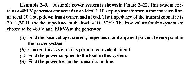
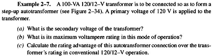
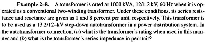
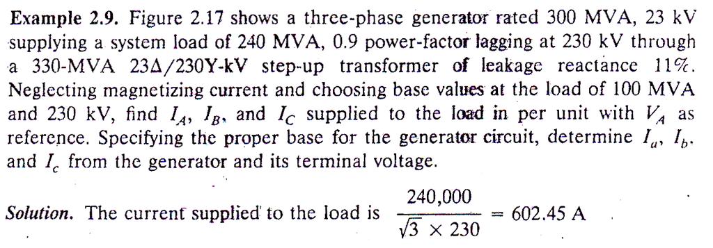
21 IMPORTANT EXAMPLES FROM power system Analysis by StevenSOn Jr. S BOOK
22
23
24
25
26
27

28 FEW IMPORTANT EXAMPLES FROM Principles of power system by v.k. mehta
29
Module 7. Transformer. Version 2 EE IIT, Kharagpur
 Module 7 Transformer Lesson 28 Problem solving on Transformers Contents 28 Problem solving on Transformer (Lesson-28) 4 28.1 Introduction. 4 28.2 Problems on 2 winding single phase transformers. 4 28.3
EQUIVALENT CIRCUIT OF A SINGLE-PHASE TRANSFORMER
 Electrical Machines Lab Experiment-No. One Date: 15-11-2016 EQUIVALENT CIRCUIT OF A SINGLE-PHASE TRANSFORMER Aim: The determination of electrical equivalent circuit parameters of a single phase power transformer
148 Electric Machines
 148 Electric Machines 3.1 The emf per turn for a single-phase 2200/220- V, 50-Hz transformer is approximately 12 V. Calculate (a) the number of primary and secondary turns, and (b) the net cross-sectional
86 chapter 2 Transformers
 86 chapter 2 Transformers Wb 1.2x10 3 0 1/60 2/60 3/60 4/60 5/60 6/60 t (sec) 1.2x10 3 FIGURE P2.2 2.3 A single-phase transformer has 800 turns on the primary winding and 400 turns on the secondary winding.
UNIVERSITY OF TECHNOLOGY By: Fadhil A. Hasan ELECTRICAL MACHINES
 UNIVERSITY OF TECHNOLOGY DEPARTMENT OF ELECTRICAL ENGINEERING Year: Second 2016-2017 By: Fadhil A. Hasan ELECTRICAL MACHINES І Module-II: AC Transformers o Single phase transformers o Three-phase transformers
PROBLEMS on Transformers
 PROBLEMS on Transformers (A) Simple Problems 1. A single-phase, 250-kVA, 11-kV/415-V, 50-Hz transformer has 80 turns on the secondary. Calculate (a) the approximate values of the primary and secondary
Chapter 2-1 Transformers
 Principles of Electric Machines and Power Electronics Chapter 2-1 Transformers Third Edition P. C. Sen Transformer application 1: power transmission Ideal Transformer Assumptions: 1. Negligible winding
INSTITUTE OF AERONAUTICAL ENGINEERING (Autonomous) Dundigal, Hyderabad ELECTRICAL AND ELECTRONICS ENGINEERING
 Dundigal, Hyderabad ELECTRICAL AND ELECTRONICS ENGINEERING") Course Name Course Code Class Branch INSTITUTE OF AERONAUTICAL ENGINEERING (Autonomous) Dundigal, Hyderabad - 500 043 ELECTRICAL AND ELECTRONICS ENGINEERING QUESTION BANK : ELECRICAL MACHINES I : A40212
Course Name Course Code Class Branch INSTITUTE OF AERONAUTICAL ENGINEERING (Autonomous) Dundigal, Hyderabad - 500 043 ELECTRICAL AND ELECTRONICS ENGINEERING QUESTION BANK : ELECRICAL MACHINES I : A40212
INSTITUTE OF AERONAUTICAL ENGINEERING (Autonomous) Dundigal, Hyderabad
 Dundigal, Hyderabad") INSTITUTE OF AERONAUTICAL ENGINEERING (Autonomous) Dundigal, Hyderabad - 00 03 ELECTRICAL AND ELECTRONICS ENGINEERING ASSIGNMENT Course Name : ELECRICAL MACHINES - II Course Code : A0 Class : II B.TECH-II
INSTITUTE OF AERONAUTICAL ENGINEERING (Autonomous) Dundigal, Hyderabad - 00 03 ELECTRICAL AND ELECTRONICS ENGINEERING ASSIGNMENT Course Name : ELECRICAL MACHINES - II Course Code : A0 Class : II B.TECH-II
INSTITUTE OF AERONAUTICAL ENGINEERING (Autonomous) Dundigal, Hyderabad
 Dundigal, Hyderabad") INSTITUTE OF AERONAUTICAL ENGINEERING (Autonomous) Dundigal, Hyderabad - 00 0 ELECTRICAL AND ELECTRONICS ENGINEERING QUESTION BANK Course Name Course Code Class Branch : ELECRICAL MACHINES - II : A0 :
INSTITUTE OF AERONAUTICAL ENGINEERING (Autonomous) Dundigal, Hyderabad - 00 0 ELECTRICAL AND ELECTRONICS ENGINEERING QUESTION BANK Course Name Course Code Class Branch : ELECRICAL MACHINES - II : A0 :
Hours / 100 Marks Seat No.
 17415 15162 3 Hours / 100 Seat No. Instructions (1) All Questions are Compulsory. (2) Answer each next main Question on a new page. (3) Illustrate your answers with neat sketches wherever necessary. (4)
Table of Contents. Table of Figures. Table of Tables
 Abstract The aim of this report is to investigate and test a transformer and check if it is good to use by doing the following tests continuity test, insulation test, polarity test, open circuit test,
MAHARASHTRA STATE BOARD OF TECHNICAL EDUCATION
 Important Instructions to examiners: 1) The answers should be examined by key words and not as word-to-word as given in the model answer scheme. 2) The model answer and the answer written by candidate
Transformer & Induction M/C
 UNIT- 2 SINGLE-PHASE TRANSFORMERS 1. Draw equivalent circuit of a single phase transformer referring the primary side quantities to secondary and explain? (July/Aug - 2012) (Dec 2012) (June/July 2014)
SECTION 4 TRANSFORMERS. Yilu (Ellen) Liu. Associate Professor Electrical Engineering Department Virginia Tech University
 Liu. Associate Professor Electrical Engineering Department Virginia Tech University") SECTION 4 TRANSFORMERS Yilu (Ellen) Liu Associate Professor Electrical Engineering Department Virginia Tech University Analysis of Transformer Turns Ratio......................... 4.2 Analysis of a Step-Up
SECTION 4 TRANSFORMERS Yilu (Ellen) Liu Associate Professor Electrical Engineering Department Virginia Tech University Analysis of Transformer Turns Ratio......................... 4.2 Analysis of a Step-Up
ECG 741 Power Distribution Transformers. Y. Baghzouz Spring 2014
 ECG 741 Power Distribution Transformers Y. Baghzouz Spring 2014 Preliminary Considerations A transformer is a device that converts one AC voltage to another AC voltage at the same frequency. The windings
Single-Phase Transformation Review
 Single-Phase Transformation Review S T U D E N T M A N U A L March 2, 2005 2 STUDENT TRAINING MANUAL Prerequisites: None Objectives: Given the Construction Standards manual and a formula sheet, you will
Transformers. gpmacademics.weebly.com
 TRANSFORMERS Syllabus: Principles of operation, Constructional Details, Losses and efficiency, Regulation of Transformer, Testing: OC & SC test. TRANSFORMER: It is a static device which transfers electric
CHAPTER 2. Transformers. Dr Gamal Sowilam
 CHAPTER Transformers Dr Gamal Sowilam Introduction A transformer is a static machine. It is not an energy conversion device, it is indispensable in many energy conversion systems. A transformer essentially
SHRI RAMSWAROOP MEMORIAL COLLEGE OF ENGG. & MANAGEMENT
 SHRI RAMSWAROOP MEMORIAL COLLEGE OF ENGG. & MANAGEMENT B.Tech. [SEM I (CE,EC,EE,EN)] QUIZ TEST-3 (Session: 2012-13) Time: 1 Hour ELECTRICAL ENGINEERING Max. Marks: 30 (EEE-101) Roll No. Academic/26 Refer/WI/ACAD/18
VALLIAMMAI ENGINEERING COLLEGE
 VALLIAMMAI ENGINEERING COLLEGE SRM Nagar, Kattankulathur 603 203 DEPARTMENT OF ELECTRONICS AND INSTRUMENTATION ENGINEERING QUESTION BANK IV SEMESTER EI6402 ELECTRICAL MACHINES Regulation 2013 Academic
Aligarh College of Engineering & Technology (College Code: 109) Affiliated to UPTU, Approved by AICTE Electrical Engg.
 Affiliated to UPTU, Approved by AICTE Electrical Engg.") Aligarh College of Engineering & Technology (College Code: 19) Electrical Engg. (EE-11/21) Unit-I DC Network Theory 1. Distinguish the following terms: (a) Active and passive elements (b) Linearity and
Aligarh College of Engineering & Technology (College Code: 19) Electrical Engg. (EE-11/21) Unit-I DC Network Theory 1. Distinguish the following terms: (a) Active and passive elements (b) Linearity and
Code No: R Set No. 1
 Code No: R05220204 Set No. 1 II B.Tech II Semester Supplimentary Examinations, Aug/Sep 2007 ELECTRICAL MACHINES-II (Electrical & Electronic Engineering) Time: 3 hours Max Marks: 80 Answer any FIVE Questions
SHRI RAMSWAROOP MEMORIAL COLLEGE OF ENGG. & MANAGEMENT B.Tech. [SEM I (EE, EN, EC, CE)] QUIZ TEST-3 (Session: ) Time: 1 Hour ELECTRICAL ENGINEE
![SHRI RAMSWAROOP MEMORIAL COLLEGE OF ENGG. & MANAGEMENT B.Tech. [SEM I (EE, EN, EC, CE)] QUIZ TEST-3 (Session: ) Time: 1 Hour ELECTRICAL ENGINEE](/thumbs/94/118213481.jpg "SHRI RAMSWAROOP MEMORIAL COLLEGE OF ENGG. & MANAGEMENT B.Tech. [SEM I (EE, EN, EC, CE)] QUIZ TEST-3 (Session: ) Time: 1 Hour ELECTRICAL ENGINEE") SHRI RAMSWAROOP MEMORIAL COLLEGE OF ENGG. & MANAGEMENT B.Tech. [SEM I (EE, EN, EC, CE)] QUIZ TEST-3 (Session: 2014-15) Time: 1 Hour ELECTRICAL ENGINEERING Max. Marks: 30 (NEE-101) Roll No. Academic/26
SHRI RAMSWAROOP MEMORIAL COLLEGE OF ENGG. & MANAGEMENT B.Tech. [SEM I (EE, EN, EC, CE)] QUIZ TEST-3 (Session: 2014-15) Time: 1 Hour ELECTRICAL ENGINEERING Max. Marks: 30 (NEE-101) Roll No. Academic/26
IVE(TY) Department of Engineering. Electrical Machines 1. Electrical Machines 1. Hour 13. slide 1
 Department of Engineering. Electrical Machines 1. Electrical Machines 1. Hour 13. slide 1") Hour 3 slide Three Phase Transformer (sect. 2.6) A set of three similar single phase transformers may be connected to form a three-phase transformer (three-phase transformer bank). The primary and secondary
Hour 3 slide Three Phase Transformer (sect. 2.6) A set of three similar single phase transformers may be connected to form a three-phase transformer (three-phase transformer bank). The primary and secondary
Experiment No. Experiments for First Year Electrical Engg Lab
 Experiment No im: To determine Regulation and Efficiency of a single phase transformer using open circuit (O.C.) and short circuit (S.C.) tests pparatus: - Single phase transformer Single phase dimmer
EEE3441 Electrical Machines Department of Electrical Engineering. Lecture. Basic Operating Principles of Transformers
 Department of Electrical Engineering Lecture Basic Operating Principles of Transformers In this Lecture Basic operating principles of following transformers are introduced Single-phase Transformers Three-phase
ELECTRICAL ENGINEERING ESE TOPIC WISE OBJECTIVE SOLVED PAPER-II
 ELECTRICAL ENGINEERING ESE TOPIC WISE OBJECTIVE SOLVED PAPER-II From (1992 2017) Office : F-126, (Lower Basement), Katwaria Sarai, New Delhi-110016 Phone : 011-26522064 Mobile : 8130909220, 9711853908
INSTITUTE OF AERONAUTICAL ENGINEERING (Autonomous) Dundigal, Hyderabad
 Dundigal, Hyderabad") INSTITUTE OF AERONAUTICAL ENGINEERING (Autonomous) Dundigal, Hyderabad -00 03 ELECTRCIAL AND ELECTRONICS ENGINEERING TUTORIAL QUESTION BANK Course Name Course Code Class Branch : DC MACHINES AND TRANSFORMERS
INSTITUTE OF AERONAUTICAL ENGINEERING (Autonomous) Dundigal, Hyderabad -00 03 ELECTRCIAL AND ELECTRONICS ENGINEERING TUTORIAL QUESTION BANK Course Name Course Code Class Branch : DC MACHINES AND TRANSFORMERS
Transformers. Dr. Gamal Sowilam
 Transformers Dr. Gamal Sowilam OBJECTIVES Become familiar with the flux linkages that exist between the coils of a transformer and how the voltages across the primary and secondary are established. Understand
MAHARASHTRA STATE BOARD OF TECHNICAL EDUCATION
 Important Instructions to examiners: 1) The answers should be examined by key words and not as word-to-word as given in the model answer scheme. 2) The model answer and the answer written by candidate
WELCOME TO THE LECTURE
 WLCOM TO TH LCTUR ON TRNFORMR Single Phase Transformer Three Phase Transformer Transformer transformer is a stationary electric machine which transfers electrical energy (power) from one voltage level
Practical Transformer on Load
 Practical Transformer on Load We now consider the deviations from the last two ideality conditions : 1. The resistance of its windings is zero. 2. There is no leakage flux. The effects of these deviations
TRANSFORMERS PART A. 2. What is the turns ratio and transformer ratio of transformer? Turns ratio = N2/ N1 Transformer = E2/E1 = I1/ I2 =K
 UNIT II TRANSFORMERS PART A 1. Define a transformer? A transformer is a static device which changes the alternating voltage from one level to another. 2. What is the turns ratio and transformer ratio of
Look over Chapter 31 sections 1-4, 6, 8, 9, 10, 11 Examples 1-8. Look over Chapter 21 sections Examples PHYS 2212 PHYS 1112
 PHYS 2212 Look over Chapter 31 sections 1-4, 6, 8, 9, 10, 11 Examples 1-8 PHYS 1112 Look over Chapter 21 sections 11-14 Examples 16-18 Good Things To Know 1) How AC generators work. 2) How to find the
PART A. 1. List the types of DC Motors. Give any difference between them. BTL 1 Remembering
 UNIT I DC MACHINES Three phase circuits, a review. Construction of DC machines Theory of operation of DC generators Characteristics of DC generators Operating principle of DC motors Types of DC motors
Question Paper Profile
 I Scheme Question Paper Profile Program Name : Electrical Engineering Program Group Program Code : EE/EP/EU Semester : Third Course Title : Electrical Circuits Max. Marks : 70 Time: 3 Hrs. Instructions:
TRANSFORMER THEORY. Mutual Induction
 Transformers Transformers are used extensively for AC power transmissions and for various control and indication circuits. Knowledge of the basic theory of how these components operate is necessary to
Electrical Machines I : Transformers
 UNIT TRANSFORMERS PART A (Q&A) 1. What is step down transformer? The transformer used to step down the voltage from primary to secondary is called as step down transformer. (Ex: /11).. Draw the noload
ELECTRICAL TECHNOLOGY
 ELECTRICAL TECHNOLOGY Subject Code: (EC303ES) Regulations : R6 JNTUH Class :II Year B.Tech ECE I Semester Department of Electronics and communication Engineering BHARAT INSTITUTE OF ENGINEERING AND TECHNOLOGY
QUESTION BANK ETE (17331) CM/IF. Chapter1: DC Circuits
 CM/IF. Chapter1: DC Circuits") QUESTION BANK ETE (17331) CM/IF Chapter1: DC Circuits Q1. State & explain Ohms law. Also explain concept of series & parallel circuit with the help of diagram. 3M Q2. Find the value of resistor in fig.
QUESTION BANK ETE (17331) CM/IF Chapter1: DC Circuits Q1. State & explain Ohms law. Also explain concept of series & parallel circuit with the help of diagram. 3M Q2. Find the value of resistor in fig.
INSTITUTE OF AERONAUTICAL ENGINEERING (Autonomous) Dundigal, Hyderabad
 Dundigal, Hyderabad") I INSTITUTE OF AERONAUTICAL ENGINEERING (Autonomous) Dundigal, Hyderabad-500043 CIVIL ENGINEERING TUTORIAL QUESTION BANK Course Name : BASIC ELECTRICAL AND ELECTRONICS ENGINEERING Course Code : AEE018
I INSTITUTE OF AERONAUTICAL ENGINEERING (Autonomous) Dundigal, Hyderabad-500043 CIVIL ENGINEERING TUTORIAL QUESTION BANK Course Name : BASIC ELECTRICAL AND ELECTRONICS ENGINEERING Course Code : AEE018
EN Assignment No.1 - TRANSFORMERS
 EN-06 - Assignment No.1 - TRANSFORMERS Date : 13 th Jan 01 Q1) A 0kVA 00/0 Volts, 60Hz, single phase transformer is found to have the following equivalent circuit parameter referred to the high potential
Code No: R Set No. 1
 Code No: R05310204 Set No. 1 III B.Tech I Semester Regular Examinations, November 2007 ELECTRICAL MACHINES-III (Electrical & Electronic Engineering) Time: 3 hours Max Marks: 80 Answer any FIVE Questions
Downloaded From All JNTU World
 Code: 9A02403 GENERATION OF ELECTRIC POWER 1 Discuss the advantages and disadvantages of a nuclear plant as compared to other conventional power plants. 2 Explain about: (a) Solar distillation. (b) Solar
Chapter 2: Transformers
 Chapter 2: Transformers 2-1. The secondary winding of a transformer has a terminal voltage of v s (t) = 282.8 sin 377t V. The turns ratio of the transformer is 100:200 (a = 0.50). If the secondary current
Chapter 30 Inductance, Electromagnetic. Copyright 2009 Pearson Education, Inc.
 Chapter 30 Inductance, Electromagnetic Oscillations, and AC Circuits 30-7 AC Circuits with AC Source Resistors, capacitors, and inductors have different phase relationships between current and voltage
El-Hawary, M.E. The Transformer Electrical Energy Systems. Series Ed. Leo Grigsby Boca Raton: CRC Press LLC, 2000
 El-Hawary, M.E. The Transformer Electrical Energy Systems. Series Ed. Leo Grigsby Boca Raton: CRC Press LLC, 000 97 Chapter 4 THE TRANSFORMER 4. NTRODUCTON The transformer is a valuable apparatus in electrical
Downloaded from / 1
 PURWANCHAL UNIVERSITY II SEMESTER FINAL EXAMINATION-2008 LEVEL : B. E. (Computer/Electronics & Comm.) SUBJECT: BEG123EL, Electrical Engineering-I Full Marks: 80 TIME: 03:00 hrs Pass marks: 32 Candidates
The power transformer
 ELEC0014 - Introduction to power and energy systems The power transformer Thierry Van Cutsem t.vancutsem@ulg.ac.be www.montefiore.ulg.ac.be/~vct November 2017 1 / 35 Power transformers are used: to transmit
3. What is hysteresis loss? Also mention a method to minimize the loss. (N-11, N-12)
") DHANALAKSHMI COLLEGE OF ENGINEERING, CHENNAI DEPARTMENT OF ELECTRICAL AND ELECTRONICS ENGINEERING EE 6401 ELECTRICAL MACHINES I UNIT I : MAGNETIC CIRCUITS AND MAGNETIC MATERIALS Part A (2 Marks) 1. List
DHANALAKSHMI COLLEGE OF ENGINEERING, CHENNAI DEPARTMENT OF ELECTRICAL AND ELECTRONICS ENGINEERING EE 6401 ELECTRICAL MACHINES I UNIT I : MAGNETIC CIRCUITS AND MAGNETIC MATERIALS Part A (2 Marks) 1. List
REV NO EXPERIMENT NO 1 AIM: To perform open and short circuit tests on 1-phase transformer and to calculate efficiency. Apparatus required:
 KARNAL INSTITUTE OF TECHNOLOGY & MANAGEMENT KUNJPURA, KARNAL LAB MANUAL OF ------- SUBJECT CODE DATE OF ISSUE: SEMESTER: BRANCH: REV NO EXPERIMENT NO 1 AIM: To perform open and short circuit tests on 1-phase
EE2022 Electrical Energy Systems
 EE0 Electrical Energy Systems Lecture : Transformer and Per Unit Analysis 7-0-0 Panida Jirutitijaroen Department of Electrical and Computer Engineering /9/0 EE0: Transformer and Per Unit Analysis by P.
Experiment 45. Three-Phase Circuits. G 1. a. Using your Power Supply and AC Voltmeter connect the circuit shown OBJECTIVE
 Experiment 45 Three-Phase Circuits OBJECTIVE To study the relationship between voltage and current in three-phase circuits. To learn how to make delta and wye connections. To calculate the power in three-phase
13. Magnetically Coupled Circuits
 13. Magnetically Coupled Circuits The change in the current flowing through an inductor induces (creates) a voltage in the conductor itself (self-inductance) and in any nearby conductors (mutual inductance)
~=E.i!=h. Pre-certification Transformers
 7 Transformers Section 26 of the electrical code governs the use and installations of transformers. A transformer is a static device used to transfer energy from one alternating current circuit to another.
Hours / 100 Marks Seat No.
 17404 21314 3 Hours / 100 Seat No. Instructions (1) All Questions are Compulsory. (2) Answer each next main Question on a new page. (3) Illustrate your answers with neat sketches wherever necessary. (4)
Phasor. Phasor Diagram of a Sinusoidal Waveform
 Phasor A phasor is a vector that has an arrow head at one end which signifies partly the maximum value of the vector quantity ( V or I ) and partly the end of the vector that rotates. Generally, vectors
1. THREE-PHASE TRANSFORMER. SHORT CIRCUIT TEST
 1. THREE-PHASE TRANSFORMER. SHORT CIRCUIT TEST 1.1 INTRODUCTION. DESCRIPTION OF THE EXPERIMENT The short-circuit test consists of measuring the input quantities of the transformer when its secondary winding
Code No: RR Set No. 1
 Code No: RR310202 Set No. 1 III B.Tech I Semester Regular Examinations, November 2006 ELECTRICAL MEASUREMENTS (Electrical & Electronic Engineering) Time: 3 hours Max Marks: 80 Answer any FIVE Questions
EE 340 Power Transformers
 EE 340 Power Transformers Preliminary considerations A transformer is a device that converts one AC voltage to another AC voltage at the same frequency. It consists of one or more coil(s) of wire wrapped
An induced emf is the negative of a changing magnetic field. Similarly, a self-induced emf would be found by
 This is a study guide for Exam 4. You are expected to understand and be able to answer mathematical questions on the following topics. Chapter 32 Self-Induction and Induction While a battery creates an
Spring 2000 EE361: MIDTERM EXAM 1
 NAME: STUDENT NUMBER: Spring 2000 EE361: MIDTERM EXAM 1 This exam is open book and closed notes. Assume f=60 hz and use the constant µ o =4π 10-7 wherever necessary. Be sure to show all work clearly. 1.
Dhanalakshmi Srinivasan Institute of Technology, Samayapuram, Trichy. Cycle 2 EE6512 Electrical Machines II Lab Manual
 Cycle 2 EE652 Electrical Machines II Lab Manual CIRCUIT DIAGRAM FOR SLIP TEST 80V DC SUPPLY 350Ω, 2 A 3 Point Starter L F A NAME PLATE DETAILS: 3Ф alternator DC shunt motor FUSE RATING: Volts: Volts: 25%
Cork Institute of Technology. Autumn 2008 Electrical Energy Systems (Time: 3 Hours)
") Cork Institute of Technology Bachelor of Science (Honours) in Electrical Power Systems - Award Instructions Answer FIVE questions. (EELPS_8_Y4) Autumn 2008 Electrical Energy Systems (Time: 3 Hours) Examiners:
Cork Institute of Technology Bachelor of Science (Honours) in Electrical Power Systems - Award Instructions Answer FIVE questions. (EELPS_8_Y4) Autumn 2008 Electrical Energy Systems (Time: 3 Hours) Examiners:
EE 221 Circuits II. Chapter 13 Magnetically Coupled Circuits
 EE Circuits II Chapter 3 Magnetically Coupled Circuits Magnetically Coupled Circuits 3. What is a transformer? 3. Mutual Inductance 3.3 Energy in a Coupled Circuit 3.4 inear Transformers 3.5 Ideal Transformers
CHAPTER 2. Basic Concepts, Three-Phase Review, and Per Unit
 CHAPTER 2 Basic Concepts, Three-Phase Review, and Per Unit 1 AC power versus DC power DC system: - Power delivered to the load does not fluctuate. - If the transmission line is long power is lost in the
APPLICATION NOTE - 018
 APPLICATION NOTE - 018 Power Transformers Background Power Transformers are used within an AC power distribution systems to increase or decrease the operating voltage to achieve the optimum transmission
Open Circuit (OC) and Short Circuit (SC) Tests on Single Phase Transformer
 and Short Circuit (SC) Tests on Single Phase Transformer") Open Circuit (OC) and Short Circuit (SC) Tests on Single Phase Transformer 1 Aim To obtain the equivalent circuit parameters from OC and SC tests, and to estimate efficiency & regulation at various loads.
Open Circuit (OC) and Short Circuit (SC) Tests on Single Phase Transformer 1 Aim To obtain the equivalent circuit parameters from OC and SC tests, and to estimate efficiency & regulation at various loads.
AC Power Instructor Notes
 Chapter 7: AC Power Instructor Notes Chapter 7 surveys important aspects of electric power. Coverage of Chapter 7 can take place immediately following Chapter 4, or as part of a later course on energy
INSTITUTE OF AERONAUTICAL ENGINEERING Dundigal, Hyderabad
 Course Name Course Code Class Branch INSTITUTE OF AERONAUTICAL ENGINEERING Dundigal, Hyderabad -500 043 AERONAUTICAL ENGINEERING TUTORIAL QUESTION BANK : ELECTRICAL AND ELECTRONICS ENGINEERING : A40203
Chapter 33. Alternating Current Circuits
 Chapter 33 Alternating Current Circuits Alternating Current Circuits Electrical appliances in the house use alternating current (AC) circuits. If an AC source applies an alternating voltage to a series
Reg. No. : BASIC ELECTRICAL TECHNOLOGY (ELE 101)
") Department of Electrical and Electronics Engineering Reg. No. : MNIPL INSTITUTE OF TECHNOLOGY, MNIPL ( Constituent Institute of Manipal University, Manipal) FIRST SEMESTER B.E. DEGREE MKEUP EXMINTION (REVISED
Department of Electrical and Electronics Engineering Reg. No. : MNIPL INSTITUTE OF TECHNOLOGY, MNIPL ( Constituent Institute of Manipal University, Manipal) FIRST SEMESTER B.E. DEGREE MKEUP EXMINTION (REVISED
ECE 3600 Transformers b
 Transformer basics and ratings A Transformer is two coils of wire that are magnetically coupled. Transformers b Transformers are only useful for AC, which is one of the big reasons electrical power is
ECE 241L Fundamentals of Electrical Engineering. Experiment 8 A-C Transformer, Magnetization & Hysteresis
 ECE 241L Fundamentals of Electrical Engineering Experiment 8 A-C Transformer, Magnetization & Hysteresis A. Objectives: I. Measure leakage inductance and resistance loss II. Measure magnetization inductance
Module 1. Introduction. Version 2 EE IIT, Kharagpur
 Module 1 Introduction Lesson 1 Introducing the Course on Basic Electrical Contents 1 Introducing the course (Lesson-1) 4 Introduction... 4 Module-1 Introduction... 4 Module-2 D.C. circuits.. 4 Module-3
Electrical Theory 2 Lessons for Fall Semester:
 Electrical Theory 2 Lessons for Fall Semester: Lesson 1 Magnetism Lesson 2 Introduction to AC Theory Lesson 3 Lesson 4 Capacitance and Capacitive Reactance Lesson 5 Impedance and AC Circuits Lesson 6 AC
Chapter 16: Mutual Inductance
 Chapter 16: Mutual Inductance Instructor: Jean-François MILLITHALER http://faculty.uml.edu/jeanfrancois_millithaler/funelec/spring2017 Slide 1 Mutual Inductance When two coils are placed close to each
 VIDYARTHIPLUS - ANNA UNIVERSITY ONLINE STUDENTS COMMUNITY UNIT 1 DC MACHINES PART A 1. State Faraday s law of Electro magnetic induction and Lenz law. 2. Mention the following functions in DC Machine (i)
1. Explain in detail the constructional details and working of DC motor.
 DHANALAKSHMI SRINIVASAN INSTITUTE OF RESEARCH AND TECHNOLOGY, PERAMBALUR DEPT OF ECE EC6352-ELECTRICAL ENGINEERING AND INSTRUMENTATION UNIT 1 PART B 1. Explain in detail the constructional details and
KNOW MORE ABOUT THE TRANSFORMERS. Glossary Transformers
 KNOW MORE ABOUT THE TRANSFORMERS Glossary Transformers Ambient temperature The existing temperature of the atmosphere surrounding a transformer installation. Ampere The practical unit of electric current.
INSTITUTE OF AERONAUTICAL ENGINEERING (AUTONOMOUS)
") Name Code Class Branch INSTITUTE OF AERONAUTICAL ENGINEERING (AUTONOMOUS) Dundigal, Hyderabad -500 043 CIVIL ENGINEERING TUTORIAL QUESTION BANK : ELECTRICAL AND ELECTRONICS ENGINEERING : A30203 : II B.
Name Code Class Branch INSTITUTE OF AERONAUTICAL ENGINEERING (AUTONOMOUS) Dundigal, Hyderabad -500 043 CIVIL ENGINEERING TUTORIAL QUESTION BANK : ELECTRICAL AND ELECTRONICS ENGINEERING : A30203 : II B.
2015 ELECTRICAL SCIENCE
 Summer 2015 ELECTRICAL SCIENCE TIME: THREE HOURS Maximum Marks : 100 Answer five questions, taking ANY TWO from GROUP A, ANY TWO from GROUP B and from GROUP C. All parts of a question (a,b,etc) should
Chapt ha e pt r e r 11 Inductors
 Chapter 11 Inductors The Basic Inductor When a length of wire is formed onto a coil, it becomes a basic inductor Magnetic lines of force around each loop in the winding of the coil effectively add to the
Unit 3 Magnetism...21 Introduction The Natural Magnet Magnetic Polarities Magnetic Compass...21
 Chapter 1 Electrical Fundamentals Unit 1 Matter...3 Introduction...3 1.1 Matter...3 1.2 Atomic Theory...3 1.3 Law of Electrical Charges...4 1.4 Law of Atomic Charges...4 Negative Atomic Charge...4 Positive
VETRI VINAYAHA COLLEGE OF ENGINEERING AND TECHNOLOGY
 VETRI VINAYAHA COLLEGE OF ENGINEERING AND TECHNOLOGY DEPARTMENT OF ELECTRICAL AND ELECTRONICS ENGINEERING I-YEAR/II-SEMESTER- EEE&ECE EE6201- CIRCUIT THEORY Two Marks with Answers PREPARED BY: Mr.A.Thirukkumaran,
Power systems 2: Transformation
 Power systems 2: Transformation Introduction In this series of articles, we will be looking at each of the main stages of the electrical power system in turn. s you will recall from our Introduction to
Chapter 33. Alternating Current Circuits
 Chapter 33 Alternating Current Circuits C HAP T E O UTLI N E 33 1 AC Sources 33 2 esistors in an AC Circuit 33 3 Inductors in an AC Circuit 33 4 Capacitors in an AC Circuit 33 5 The L Series Circuit 33
Preface...x Chapter 1 Electrical Fundamentals
 Preface...x Chapter 1 Electrical Fundamentals Unit 1 Matter...3 Introduction...3 1.1 Matter...3 1.2 Atomic Theory...3 1.3 Law of Electrical Charges...4 1.4 Law of Atomic Charges...5 Negative Atomic Charge...5
Downloaded From JNTU World. B.Tech II Year II Semester (R09) Supplementary Examinations December/January 2014/2015 GENERATION OF ELECTRIC POWER
 Supplementary Examinations December/January 2014/2015 GENERATION OF ELECTRIC POWER") Downloaded From Code: 9A02403 B.Tech II Year II Semester () Supplementary Examinations December/January 2014/2015 GENERATION OF ELECTRIC POWER Answer any FIVE questions 1 Discuss the advantages and disadvantages
Downloaded From Code: 9A02403 B.Tech II Year II Semester () Supplementary Examinations December/January 2014/2015 GENERATION OF ELECTRIC POWER Answer any FIVE questions 1 Discuss the advantages and disadvantages
Course ELEC Introduction to electric power and energy systems. Additional exercises with answers December reactive power compensation
 Course ELEC0014 - Introduction to electric power and energy systems Additional exercises with answers December 2017 Exercise A1 Consider the system represented in the figure below. The four transmission
1. (a) Determine the value of Resistance R and current in each branch when the total current taken by the curcuit in figure 1a is 6 Amps.
 Determine the value of Resistance R and current in each branch when the total current taken by the curcuit in figure 1a is 6 Amps.") Code No: 07A3EC01 Set No. 1 II B.Tech I Semester Regular Examinations, November 2008 ELECTRICAL AND ELECTRONICS ENGINEERING ( Common to Civil Engineering, Mechanical Engineering, Mechatronics, Production
Code No: 07A3EC01 Set No. 1 II B.Tech I Semester Regular Examinations, November 2008 ELECTRICAL AND ELECTRONICS ENGINEERING ( Common to Civil Engineering, Mechanical Engineering, Mechatronics, Production
Alternating Current. Slide 1 / 69. Slide 2 / 69. Slide 3 / 69. Topics to be covered. Sources of Alternating EMF. Sources of alternating EMF
 Slide 1 / 69 lternating urrent Sources of alternating EMF Transformers ircuits and Impedance Topics to be covered Slide 2 / 69 LR Series ircuits Resonance in ircuit Oscillations Sources of lternating EMF
Alternating Current. Slide 2 / 69. Slide 1 / 69. Slide 3 / 69. Slide 4 / 69. Slide 6 / 69. Slide 5 / 69. Topics to be covered
 Slide 1 / 69 lternating urrent Sources of alternating EMF ircuits and Impedance Slide 2 / 69 Topics to be covered LR Series ircuits Resonance in ircuit Oscillations Slide 3 / 69 Sources of lternating EMF
Review: Lecture 9. Instantaneous and Average Power. Effective or RMS Value. Apparent Power and Power Factor. Complex Power. Conservation of AC Power
 Review: Lecture 9 Instantaneous and Average Power p( t) VmI m cos ( v i ) VmI m cos ( t v i ) Maximum Average Power Transfer Z L R L jx Effective or RMS Value I rms I m L R P * TH Apparent Power and Power
Methods of secondary short circuit current control in single phase transformers
 2015; 1(8): 412-417 ISSN Print: 2394-7500 ISSN Online: 2394-5869 Impact Factor: 5.2 IJAR 2015; 1(8): 412-417 www.allresearchjournal.com Received: 17-05-2015 Accepted: 20-06-2015 Parantap Nandi A/2, Building
Module 7. Transformer. Version 2 EE IIT, Kharagpur
 Module 7 Transformer Lesson 3 Ideal Transformer Contents 3 Ideal Transformer (Lesson: 3) 4 3. Goals of the lesson 4 3. Introduction.. 5 3.. Principle of operation.. 5 3.3 Ideal Transformer.. 6 3.3. Core
ELECTROMAGNETIC INDUCTION AND ALTERNATING CURRENT (Assignment)
") ELECTROMAGNETIC INDUCTION AND ALTERNATING CURRENT (Assignment) 1. In an A.C. circuit A ; the current leads the voltage by 30 0 and in circuit B, the current lags behind the voltage by 30 0. What is the
ELECTROMAGNETIC INDUCTION AND ALTERNATING CURRENT (Assignment) 1. In an A.C. circuit A ; the current leads the voltage by 30 0 and in circuit B, the current lags behind the voltage by 30 0. What is the
VOLTAGE AND CURRENT RELATIONS AND POWER PART1: THREE PHASE VOLTAGE AND CURRENT RELATIONSHIPS
 Islamic University of Gaza Faculty of Engineering Electrical Engineering department Electric Machine Lab Eng. Omar A. Qarmout Eng. Amani S. Abu Reyala Experiment 2 THREE PHASE AC CIRCUITS: VOLTAGE AND
PURCHASE SPECIFICATIONS 500KVA DRY TYPE TRANSFORMER FOR OIL RIG APPLICATIONS
 PURCHASE SPECIFICATIONS OF 500KVA DRY TYPE TRANSFORMER FOR OIL RIG APPLICATIONS SPECIFICATION NO. : OR12423 REVISION NO. : Rev 00 DATE : 01.03.2011 DISTRIBUTION : PI - 4 copies O/C - 1 copy PREPARED BY