TRANSFORMER OPERATION
|
|
|
- Kristin Nicholson
- 5 years ago
- Views:
Transcription

1 Chapter 3 TRANSFORMER OPERATION 1


2 A transformer is a static device (no moving parts) used to transfer energy from one AC circuit to another. This transfer of energy may involve an increase or decrease in voltage, but the frequency will be the same in both circuits. 440 V 60 Hz 120 V 60 Hz The two circuits of a transformer are coupled by a magnetic field that is linked to both instead of a conductive electrical path. A transformer can only be operated with AC voltage because no voltage is induced if there is no change 2010, The McGraw-Hill Companies, in the Inc. magnetic field. 2


3 A transformer doesn't change power levels between circuits. If you put 100 VA into a transformer, 100 VA (minus a small amount of losses) comes out. Input 100 V x 1 A = Input 100 VA = 25 V x 4 A Output 100 VA Output The transformer consists of two electrical conductors called the primary winding and the secondary winding. The primary winding is fed from a varying alternating current which creates a varying magnetic field around it. According to the principle of "mutual inductance", the secondary winding, which is in this varying magnetic field, will have a voltage induced into it. Primary Secondary 3


4 If the primary has more turns than the secondary, you have a step-down transformer that reduces the voltage. If the primary has fewer turns than the secondary, you have a step-up transformer that increases the voltage. If the primary has the same number of turns as the secondary, the outgoing secondary voltage will be the same as the incoming primary voltage. This is the case for an isolation transformer. In certain exceptional cases, one large coil of wire can serve as both the primary and secondary. This is the case with auto-transformers. 4
5 TRANSFORMER VOLTAGE, CURRENT, and TURNS RATIO The ratio of turns in a transformer's primary winding to those in its secondary winding is known as the turns ratio and is the same as the transformer's s voltage ratio. The voltage ratio of an ideal transformer (one with no losses) is directly related to the turns ratio, while the current ratio is inversely related to the turns ratio. 5


6 12 T 120 V 8 A 3 T 30 V 2 A Turns Ratio 4:1 Voltage Ratio 4:1 Current Ratio 1:4 Examples of common single-phase transformer turns ratios base on primary and secondary voltage ratings. The actual number of turns is not important, just the turns ratio. A Transformer Turns Ratio Test Set can directly measure the turns ratio. 6


7 Step-Up Transformer Equations If the voltage of the primary winding and the turns ratio are known, the voltage of the secondary winding can be determined. Turns Ratio = 1:2 7


8 If the voltage of the secondary winding and the turns ratio are known, the voltage of the primary winding can be determined. Turns Ratio = 1:2 If the current of the primary winding and the turns ratio are known, the current of the secondary winding can be determined. Turns Ratio = 1:2 8


9 If the current of the secondary winding and the turns ratio are known, the current of the primary winding can be determined. Turns Ratio = 1:2 Step-Down Transformer Equations 9


10 If the voltage of the primary winding and the turns ratio are known, the voltage of the secondary winding can be determined. Turns Ratio = 20:1 If the voltage of the secondary winding and the turns ratio are known, the voltage of the primary winding can be determined. Turns Ratio = 20:1 10


11 If the current of the primary winding and the turns ratio are known, the current of the secondary winding can be determined. Turns Ratio = 20:1 If the current of the secondary winding and the turns ratio are known, the current of the primary winding can be determined. Turns Ratio = 20:1 11


12 A transformer automatically adjusts its input current to meet the requirements of its output or load current. If no load is connected to the secondary winding, only a small amount of current known as the magnetizing current or exciting current current flows through the primary winding. Exciting Current For a purely resistive load, according to Ohm's law, the amount of secondary winding current equals the secondary voltage divided by the value of the load resistance connected to the secondary circuit (a negligible coil winding resistance assumed). I I =V/R V R 12
13 Primary Current Secondary Current Turns Ratio = 20:1 TRANSFORMER POWER RATING 13


14 Just as horsepower ratings designate the power capacity of an electric motor, a transformer s kva rating indicates its maximum power output capacity. The maximum power rating of a transformer can be found on the transformer's nameplate. There is no gain or loss in energy in an ideal transformer when energy is transferred. This means that the volts multiplied by the amperes of the primary circuit equal the volts multiplied by the amperes of the secondary circuit. it 10A IDEAL 5A 120 V 240V TRANSFORMER VA (primary) = 120 x 10 = 1200 VA VA (secondary) = 2400 x 5 = 1200 VA 14
 is the total power supplied to the circuit from")

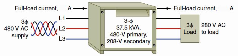
15 Transformers are rated in volt-amperes (VA) or kilovolt-amperes (kva). You may recall that volt-amps (VA) is the total power supplied to the circuit from the source, and includes real (Watts) and reactive (VAR) power. The primary and secondary full-load current usually are not given but can be calculated using the power rating as follows: 15
16 16
Review 6. unlike poles cause the magnets to attract. like poles cause the magnets to repel.
 Review 6 1. The two characteristics of all magnets are: they attract and hold Iron, and, if free to move, they will assume roughly a south - north position. 2. Lines of flux always leave the north pole
Power. Power is the rate of using energy in joules per second 1 joule per second Is 1 Watt
 3 phase Power All we need electricity for is as a source of transport for energy. We can connect to a battery, which is a source of stored energy. Or we can plug into and electric socket at home or in
Single-Phase Transformation Review
 Single-Phase Transformation Review S T U D E N T M A N U A L March 2, 2005 2 STUDENT TRAINING MANUAL Prerequisites: None Objectives: Given the Construction Standards manual and a formula sheet, you will
Chapter 7. Copyright The McGraw-Hill Companies, Inc. Permission required for reproduction or display.
 Chapter 7 Copyright The McGraw-Hill Companies, Inc. Permission required for reproduction or display. Learning Objectives 1. Understand the meaning of instantaneous and average power, master AC power notation,
~=E.i!=h. Pre-certification Transformers
 7 Transformers Section 26 of the electrical code governs the use and installations of transformers. A transformer is a static device used to transfer energy from one alternating current circuit to another.
Electrical Theory 2 Lessons for Fall Semester:
 Electrical Theory 2 Lessons for Fall Semester: Lesson 1 Magnetism Lesson 2 Introduction to AC Theory Lesson 3 Lesson 4 Capacitance and Capacitive Reactance Lesson 5 Impedance and AC Circuits Lesson 6 AC
Trade of Electrician. The Transformer
 Trade of Electrician Standards Based Apprenticeship The Transformer Phase 2 Module No. 2.1 Unit No. 2.1.10 COURSE NOTES Created by Gerry Ryan - Galway TC Revision 1 April 2000 by Gerry Ryan - Galway TC
UNIVERSITY OF TECHNOLOGY By: Fadhil A. Hasan ELECTRICAL MACHINES
 UNIVERSITY OF TECHNOLOGY DEPARTMENT OF ELECTRICAL ENGINEERING Year: Second 2016-2017 By: Fadhil A. Hasan ELECTRICAL MACHINES І Module-II: AC Transformers o Single phase transformers o Three-phase transformers
1 K Hinds 2012 TRANSFORMERS
 1 K Hinds 2012 TRANSFORMERS A transformer changes electrical energy of a given voltage into electrical energy at a different voltage level. It consists of two coils which are not electrically connected,
Transformers 1 of 25 Boardworks Ltd 2016
 Transformers 1 of 25 Boardworks Ltd 2016 Transformers 2 of 25 Boardworks Ltd 2016 Linking circuits with magnetism 3 of 25 Boardworks Ltd 2016 Transformers 4 of 25 Boardworks Ltd 2016 Power can be transferred
Exercise 10. Transformers EXERCISE OBJECTIVE DISCUSSION OUTLINE DISCUSSION. Introduction to transformers
 Exercise 10 Transformers EXERCISE OBJECTIVE When you have completed this exercise, you will be familiar with the basic operating principles of transformers, as well as with the different ratios of transformers:
SECTION 4 TRANSFORMERS. Yilu (Ellen) Liu. Associate Professor Electrical Engineering Department Virginia Tech University
 Liu. Associate Professor Electrical Engineering Department Virginia Tech University") SECTION 4 TRANSFORMERS Yilu (Ellen) Liu Associate Professor Electrical Engineering Department Virginia Tech University Analysis of Transformer Turns Ratio......................... 4.2 Analysis of a Step-Up
SECTION 4 TRANSFORMERS Yilu (Ellen) Liu Associate Professor Electrical Engineering Department Virginia Tech University Analysis of Transformer Turns Ratio......................... 4.2 Analysis of a Step-Up
AUTO-TRANSFORMER. This is having only one winding; part of this winding is common to both primary and secondary.
 AUTO-TRANSFORMER This is having only one winding; part of this winding is common to both primary and secondary. In 2-winding transformer both primary and secondary windings are electrically isolated, but
TRANSFORMERS INTRODUCTION
 Tyco Electronics Corporation Crompton Instruments 1610 Cobb International Parkway, Unit #4 Kennesaw, GA 30152 Tel. 770-425-8903 Fax. 770-423-7194 TRANSFORMERS INTRODUCTION A transformer is a device that
Chapter 11. Alternating Current
 Unit-2 ECE131 BEEE Chapter 11 Alternating Current Objectives After completing this chapter, you will be able to: Describe how an AC voltage is produced with an AC generator (alternator) Define alternation,
GENERATOR INTERCONNECTION APPLICATION FOR ALL PROJECTS WITH AGGREGATE GENERATOR OUTPUT OF MORE THAN 2 MW
 GENERATOR INTERCONNECTION APPLICATION FOR ALL PROJECTS WITH AGGREGATE GENERATOR OUTPUT OF MORE THAN 2 MW Electric Utility Contact Information DTE Energy Interconnection Coordinator One Energy Plaza, SB
Experiment 45. Three-Phase Circuits. G 1. a. Using your Power Supply and AC Voltmeter connect the circuit shown OBJECTIVE
 Experiment 45 Three-Phase Circuits OBJECTIVE To study the relationship between voltage and current in three-phase circuits. To learn how to make delta and wye connections. To calculate the power in three-phase
Power System Analysis Prof. A. K. Sinha Department of Electrical Engineering Indian institute of Technology, Kharagpur
 Power System Analysis Prof. A. K. Sinha Department of Electrical Engineering Indian institute of Technology, Kharagpur Lecture - 10 Transmission Line Steady State Operation Voltage Control (Contd.) Welcome
Electrical Theory. Power Principles and Phase Angle. PJM State & Member Training Dept. PJM /22/2018
 Electrical Theory Power Principles and Phase Angle PJM State & Member Training Dept. PJM 2018 Objectives At the end of this presentation the learner will be able to: Identify the characteristics of Sine
EE2003 Circuit Theory Chapter 13 Magnetically Coupled Circuits
 EE003 Circuit Theory Chapter 3 Magnetically Coupled Circuits Copyright The McGraw-Hill Companies, Inc. Permission required for reproduction or display. Magnetically Coupled Circuit Chapter 3 3. What is
Paper number: Principles of electrical and electronics technology Paper series: December Practice
 Paper number: 850-56 Paper series: December 04 Question Syllabus reference Question 0.0 a) i) Tesla. ii) Newton. iii) Henry. Marks mark each 4 0.0 0.0 0.0 i) Megavolt ii) Microvolt. a) Directly Inversely
GENERATOR INTERCONNECTION APPLICATION FOR ALL PROJECTS WITH AGGREGATE GENERATOR OUTPUT OF MORE THAN 150 KW BUT LESS THAN OR EQUAL TO 550 KW
 GENERATOR INTERCONNECTION APPLICATION FOR ALL PROJECTS WITH AGGREGATE GENERATOR OUTPUT OF MORE THAN 150 KW BUT LESS THAN OR EQUAL TO 550 KW Electric Utility Contact Information Detroit Edison Company Interconnection
Unit 3 Magnetism...21 Introduction The Natural Magnet Magnetic Polarities Magnetic Compass...21
 Chapter 1 Electrical Fundamentals Unit 1 Matter...3 Introduction...3 1.1 Matter...3 1.2 Atomic Theory...3 1.3 Law of Electrical Charges...4 1.4 Law of Atomic Charges...4 Negative Atomic Charge...4 Positive
Preface...x Chapter 1 Electrical Fundamentals
 Preface...x Chapter 1 Electrical Fundamentals Unit 1 Matter...3 Introduction...3 1.1 Matter...3 1.2 Atomic Theory...3 1.3 Law of Electrical Charges...4 1.4 Law of Atomic Charges...5 Negative Atomic Charge...5
Experiment 6. Electromagnetic Induction and transformers
 Experiment 6. Electromagnetic Induction and transformers 1. Purpose Confirm the principle of electromagnetic induction and transformers. 2. Principle The PASCO scientific SF-8616 Basic Coils Set and SF-8617
5.0 THREE PHASE SYSTEM
 5.0 THREE PHASE SYSTEM ET 201 BAKISS HIYANA BAU BAKAR JKE, POLISAS 1 COURSE LEARNING OUTCOME 1. Explain AC circuit concept and their analysis using AC circuit law. 2. Apply the knowledge of AC circuit
ESO 210 Introduction to Electrical Engineering
 ESO 210 Introduction to Electrical Engineering Lecture-19 Magnetic Circuits and Introduction to Transformers 2 SERIES CONNECTION OF MUTUALLY COUPLED COILS A mutual term will alter the total inductance
CHAPTER 2. Transformers. Dr Gamal Sowilam
 CHAPTER Transformers Dr Gamal Sowilam Introduction A transformer is a static machine. It is not an energy conversion device, it is indispensable in many energy conversion systems. A transformer essentially
Chapter 2-1 Transformers
 Principles of Electric Machines and Power Electronics Chapter 2-1 Transformers Third Edition P. C. Sen Transformer application 1: power transmission Ideal Transformer Assumptions: 1. Negligible winding
ELG 4125: ELECTRICAL POWER TRANSMISSION AND DISTRIBUTION: TUTORIAL 1: - BY:
 ELG 4125: ELECTRICAL POWER TRANSMISSION AND DISTRIBUTION: TUTORIAL 1: - BY: Faizhussain Arsiwala POWER FACTOR: The cosine of angle between voltage and current in an a.c. circuit is known as power factor.
Chapt ha e pt r e r 11 Inductors
 Chapter 11 Inductors The Basic Inductor When a length of wire is formed onto a coil, it becomes a basic inductor Magnetic lines of force around each loop in the winding of the coil effectively add to the
3. What is hysteresis loss? Also mention a method to minimize the loss. (N-11, N-12)
") DHANALAKSHMI COLLEGE OF ENGINEERING, CHENNAI DEPARTMENT OF ELECTRICAL AND ELECTRONICS ENGINEERING EE 6401 ELECTRICAL MACHINES I UNIT I : MAGNETIC CIRCUITS AND MAGNETIC MATERIALS Part A (2 Marks) 1. List
DHANALAKSHMI COLLEGE OF ENGINEERING, CHENNAI DEPARTMENT OF ELECTRICAL AND ELECTRONICS ENGINEERING EE 6401 ELECTRICAL MACHINES I UNIT I : MAGNETIC CIRCUITS AND MAGNETIC MATERIALS Part A (2 Marks) 1. List
Transformer circuit calculations
 Transformer circuit calculations This worksheet and all related files are licensed under the Creative Commons Attribution License, version 1.0. To view a copy of this license, visit http://creativecommons.org/licenses/by/1.0/,
12.6 Delta Phase versus Line Current
 Unit 12 Delta/Delta and Delta/Wye Transformers Electrical NEC Exam Preparation 12.6 Delta Phase versus Line Current Since each line conductor from a delta transformer is actually connected to two transformer
Transformer Book page Syllabus
 Transformer Book page 193 194 Syllabus 6.17 6.20 cgrahamphysics.com 2015 How well do you know your performers? Optimus prime Drift Bumblebee Step down transformer cgrahamphysics.com 2015 Step up transformer
TRANSFORMER THEORY. Mutual Induction
 Transformers Transformers are used extensively for AC power transmissions and for various control and indication circuits. Knowledge of the basic theory of how these components operate is necessary to
PART 1 OWNER/APPLICANT INFORMATION
 CALHOUN COUNTY ELECTRIC COOP. ASSN. Application for Operation of Customer-Owned Generation This application should be completed as soon as possible and returned to the Cooperative in order to begin processing
12.6 Delta Phase versus Line Current
 Unit 12 Delta/Delta and Delta/Wye Transformers Electrical NEC Exam Preparation 12.6 Delta Phase versus Line Current Since each line conductor from a delta transformer is actually connected to two transformer
Unit 27 Three-Phase Circuits
 Unit 27 Three-Phase Circuits Objectives: Discuss the differences between threephase and single-phase voltages. Discuss the characteristics of delta and wye connections. Compute voltage and current values
CHAPTER 2. Basic Concepts, Three-Phase Review, and Per Unit
 CHAPTER 2 Basic Concepts, Three-Phase Review, and Per Unit 1 AC power versus DC power DC system: - Power delivered to the load does not fluctuate. - If the transmission line is long power is lost in the
QUESTION BANK ETE (17331) CM/IF. Chapter1: DC Circuits
 CM/IF. Chapter1: DC Circuits") QUESTION BANK ETE (17331) CM/IF Chapter1: DC Circuits Q1. State & explain Ohms law. Also explain concept of series & parallel circuit with the help of diagram. 3M Q2. Find the value of resistor in fig.
QUESTION BANK ETE (17331) CM/IF Chapter1: DC Circuits Q1. State & explain Ohms law. Also explain concept of series & parallel circuit with the help of diagram. 3M Q2. Find the value of resistor in fig.
EE 221 Circuits II. Chapter 13 Magnetically Coupled Circuits
 EE Circuits II Chapter 3 Magnetically Coupled Circuits Magnetically Coupled Circuits 3. What is a transformer? 3. Mutual Inductance 3.3 Energy in a Coupled Circuit 3.4 inear Transformers 3.5 Ideal Transformers
SECTION 3 BASIC AUTOMATIC CONTROLS UNIT 12 BASIC ELECTRICITY AND MAGNETISM. Unit Objectives. Unit Objectives 2/29/2012
 SECTION 3 BASIC AUTOMATIC CONTROLS UNIT 12 BASIC ELECTRICITY AND MAGNETISM Unit Objectives Describe the structure of an atom. Identify atoms with a positive charge and atoms with a negative charge. Explain
Chapter 1 Electrical Theory and Part C Series Parallel and Code Questions Multiwire Branch Circuits Unit 1 Electrician s Math
 Chapter 1 Electrical Theory and Code Questions 1 Unit 1 Electrician s Math and Basic Electrical Formulas 3 Part A Electrician s Math 3 1 1 Fractions 3 1 2 Kilo 4 1 3 Knowing Your Answer 4 1 4 Multiplier
DESIGN AND CONSTRUCTION OF 1500VA VARIABLE OUTPUT STEP DOWN TRANSFORMER
 DESIGN AND CONSTRUCTION OF 1500VA VARIABLE OUTPUT STEP DOWN TRANSFORMER OGUNDARE AYOADE B., OMOGOYE O. SAMUEL & OLUWASANYA OMOTAYO J. Department of Electrical/Electronic engineering, Lagos State Polytechnic,
INSTITUTE OF AERONAUTICAL ENGINEERING (AUTONOMOUS) Dundigal, Hyderabad
 Dundigal, Hyderabad") INSTITUTE OF AERONAUTICAL ENGINEERING (AUTONOMOUS) Dundigal, Hyderabad - 500 043 CIVIL ENGINEERING ASSIGNMENT Name : Electrical and Electronics Engineering Code : A30203 Class : II B. Tech I Semester Branch
INSTITUTE OF AERONAUTICAL ENGINEERING (AUTONOMOUS) Dundigal, Hyderabad - 500 043 CIVIL ENGINEERING ASSIGNMENT Name : Electrical and Electronics Engineering Code : A30203 Class : II B. Tech I Semester Branch
In this lecture. Electromagnetism. Electromagnetism. Oersted s Experiment. Electricity & magnetism are different aspects of the same basic phenomenon:
 In this lecture Electromagnetism Electromagnetic Effect Electromagnets Electromechanical Devices Transformers Electromagnetic Effect Electricity & magnetism are different aspects of the same basic phenomenon:
EEE3441 Electrical Machines Department of Electrical Engineering. Lecture. Basic Operating Principles of Transformers
 Department of Electrical Engineering Lecture Basic Operating Principles of Transformers In this Lecture Basic operating principles of following transformers are introduced Single-phase Transformers Three-phase
EASTERN ILLINI ELECTRIC COOPERATIVE Application for Operation of Member-Owned Generation
 EASTERN ILLINI ELECTRIC COOPERATIVE Application for Operation of Member-Owned Generation This application is to be completed and returned to the Cooperative member service representative in order to begin
A Practical Guide to Free Energy Devices
 A Practical Guide to Free Energy Devices Device Patent No 30: Last updated: 24th June 2007 Author: Patrick J. Kelly This patent shows a method of altering a standard electrical generator intended to be
CHAPTER 4. Distribution Transformers
 CHAPTER 4 Distribution Transformers Introduction A transformer is an electrical device that transfers energy from one circuit to another purely by magnetic coupling. Relative motion of the parts of the
INSTITUTE OF AERONAUTICAL ENGINEERING (Autonomous) Dundigal, Hyderabad
 Dundigal, Hyderabad") I INSTITUTE OF AERONAUTICAL ENGINEERING (Autonomous) Dundigal, Hyderabad-500043 CIVIL ENGINEERING TUTORIAL QUESTION BANK Course Name : BASIC ELECTRICAL AND ELECTRONICS ENGINEERING Course Code : AEE018
I INSTITUTE OF AERONAUTICAL ENGINEERING (Autonomous) Dundigal, Hyderabad-500043 CIVIL ENGINEERING TUTORIAL QUESTION BANK Course Name : BASIC ELECTRICAL AND ELECTRONICS ENGINEERING Course Code : AEE018
Exercise 1: Power Division
 Power in AC Circuits AC 2 Fundamentals Exercise 1: Power Division EXERCISE OBJECTIVE When you have completed this exercise, you will be able to determine ac power division among the components of an RLC
GENERATOR INTERCONNECTION APPLICATION Category 5 For All Projects with Aggregate Generator Output of More Than 2 MW
 GENERATOR INTERCONNECTION APPLICATION Category 5 For All Projects with Aggregate Generator Output of More Than 2 MW ELECTRIC UTILITY CONTACT INFORMATION Consumers Energy Interconnection Coordinator 1945
Table of Contents. Table of Figures. Table of Tables
 Abstract The aim of this report is to investigate and test a transformer and check if it is good to use by doing the following tests continuity test, insulation test, polarity test, open circuit test,
By Gill ( ) PDF created with FinePrint pdffactory trial version
 PDF created with FinePrint pdffactory trial version") By Gill (www.angelfire.com/al4/gill ) 1 Introduction One of the main reasons of adopting a.c. system instead of d.c. for generation, transmission and distribution of electrical power is that alternatin
By Gill (www.angelfire.com/al4/gill ) 1 Introduction One of the main reasons of adopting a.c. system instead of d.c. for generation, transmission and distribution of electrical power is that alternatin
Owner/Customer Name: Mailing Address: City: County: State: Zip Code: Phone Number: Representative: Address: Fax Number:
 Interconnection of a Customer-Owned Renewable Generation System of Greater than 100 KW and Less than or Equal to 1 MW to the LCEC Electric Grid Tier 3 Application and Compliance Form Instructions: Complete
SHRI RAMSWAROOP MEMORIAL COLLEGE OF ENGG. & MANAGEMENT B.Tech. [SEM I (EE, EN, EC, CE)] QUIZ TEST-3 (Session: ) Time: 1 Hour ELECTRICAL ENGINEE
![SHRI RAMSWAROOP MEMORIAL COLLEGE OF ENGG. & MANAGEMENT B.Tech. [SEM I (EE, EN, EC, CE)] QUIZ TEST-3 (Session: ) Time: 1 Hour ELECTRICAL ENGINEE](/thumbs/94/118213481.jpg "SHRI RAMSWAROOP MEMORIAL COLLEGE OF ENGG. & MANAGEMENT B.Tech. [SEM I (EE, EN, EC, CE)] QUIZ TEST-3 (Session: ) Time: 1 Hour ELECTRICAL ENGINEE") SHRI RAMSWAROOP MEMORIAL COLLEGE OF ENGG. & MANAGEMENT B.Tech. [SEM I (EE, EN, EC, CE)] QUIZ TEST-3 (Session: 2014-15) Time: 1 Hour ELECTRICAL ENGINEERING Max. Marks: 30 (NEE-101) Roll No. Academic/26
SHRI RAMSWAROOP MEMORIAL COLLEGE OF ENGG. & MANAGEMENT B.Tech. [SEM I (EE, EN, EC, CE)] QUIZ TEST-3 (Session: 2014-15) Time: 1 Hour ELECTRICAL ENGINEERING Max. Marks: 30 (NEE-101) Roll No. Academic/26
Walchand Institute of Technology. Basic Electrical and Electronics Engineering. Transformer
 Walchand Institute of Technology Basic Electrical and Electronics Engineering Transformer 1. What is transformer? explain working principle of transformer. Electrical power transformer is a static device
Practical Tricks with Transformers. Larry Weinstein K0NA
 Practical Tricks with Transformers Larry Weinstein K0NA Practical Tricks with Transformers Quick review of inductance and magnetics Switching inductive loads How many voltages can we get out of a $10 Home
Transformer & Induction M/C
 UNIT- 2 SINGLE-PHASE TRANSFORMERS 1. Draw equivalent circuit of a single phase transformer referring the primary side quantities to secondary and explain? (July/Aug - 2012) (Dec 2012) (June/July 2014)
Cornerstone Electronics Technology and Robotics Week 32 Transformers
 Cornerstone Electronics Technology and Robotics Week 32 Transformers Administration: o Prayer o Turn in quiz Electricity and Electronics, Section 12.1, Transformer Theory: o A transformer is a device that
HPS Universal BUCK-BOOST TRANSFORMERS
 BUCK-BOOST TRANSFORMERS Single and Three Phase Potted Buck-Boost Transformers Buck-Boost Applications & Standard Specification... 80 Selecting Buck-Boost Transformers... 81 Single Phase Selection Tables...
Transformers. Objectives
 Transformers Objectives Explain mutual inductance Describe how a transformer is constructed and how it works Explain how a step-up transformer works Explain how a step-down transformer works Discuss the
A Practical Guide to Free Energy Devices
 A Practical Guide to Free Energy Devices Part PatD14: Last updated: 25th February 2006 Author: Patrick J. Kelly This patent application shows the details of a device which it is claimed, can produce sufficient
Hours / 100 Marks Seat No.
 17415 15162 3 Hours / 100 Seat No. Instructions (1) All Questions are Compulsory. (2) Answer each next main Question on a new page. (3) Illustrate your answers with neat sketches wherever necessary. (4)
Electrical Machines I : Transformers
 UNIT TRANSFORMERS PART A (Q&A) 1. What is step down transformer? The transformer used to step down the voltage from primary to secondary is called as step down transformer. (Ex: /11).. Draw the noload
GENERATOR INTERCONNECTION APPLICATION Category 3 For All Projects with Aggregate Generator Output of More Than 150 kw but Less Than or Equal to 550 kw
 GENERATOR INTERCONNECTION APPLICATION Category 3 For All Projects with Aggregate Generator Output of More Than 150 kw but Less Than or Equal to 550 kw ELECTRIC UTILITY CONTACT INFORMATION Consumers Energy
Short-Circuit Current Calculations
 Basic Point-to-Point Calculation Procedure Step. Determine the transformer full load amps (F.L.A.) from either the nameplate, the following formulas or Table : Multiplier = 00 *% Z transformer Step 2.
UEE11 Electrotechnology. Training Package
 UEE11 Electrotechnology Training Package UEENEEJ153A Find and rectify faults in motors and associated controls in refrigeration and air conditioning systems Learner Workbook Version 1 Training and Education
Aligarh College of Engineering & Technology (College Code: 109) Affiliated to UPTU, Approved by AICTE Electrical Engg.
 Affiliated to UPTU, Approved by AICTE Electrical Engg.") Aligarh College of Engineering & Technology (College Code: 19) Electrical Engg. (EE-11/21) Unit-I DC Network Theory 1. Distinguish the following terms: (a) Active and passive elements (b) Linearity and
Aligarh College of Engineering & Technology (College Code: 19) Electrical Engg. (EE-11/21) Unit-I DC Network Theory 1. Distinguish the following terms: (a) Active and passive elements (b) Linearity and
ELG2336 Introduction to Electric Machines
 ELG2336 Introduction to Electric Machines Magnetic Circuits DC Machine Shunt: Speed control Series: High torque Permanent magnet: Efficient AC Machine Synchronous: Constant speed Induction machine: Cheap
TRANSFORMERS PART A. 2. What is the turns ratio and transformer ratio of transformer? Turns ratio = N2/ N1 Transformer = E2/E1 = I1/ I2 =K
 UNIT II TRANSFORMERS PART A 1. Define a transformer? A transformer is a static device which changes the alternating voltage from one level to another. 2. What is the turns ratio and transformer ratio of
SOUTH CENTRAL INDIANA REMC Application for Operation of Member-Owned Small Power Generation Systems
 SOUTH CENTRAL INDIANA REMC Application for Operation of Member-Owned Small Power Generation Systems This application should be completed as soon as possible and returned to the Cooperative in order to
Book pg Syllabus
 Book pg. 193 194 Syllabus 6.17 6.20 www.cgrahamphysics.com Transformers - YouTube [720p].mp4 Not me a real transformer www.cgrahamphysics.com Understand how transformers work ALL State the func,on of step
Electromagnetic Induction
 Chapter 16 Electromagnetic Induction In This Chapter: Electromagnetic Induction Faraday s Law Lenz s Law The Transformer Self-Inductance Inductors in Combination Energy of a Current-Carrying Inductor Electromagnetic
ELECTRIC CURRENTS AND CIRCUITS By: Richard D. Beard P.E.
 ELECTRICAL POWER There are two types of electric power in use, direct current (dc) and alternating current (ac). The most common use of direct current is automotive, including storage batteries, starter
WELCOME TO THE LECTURE
 WLCOM TO TH LCTUR ON TRNFORMR Single Phase Transformer Three Phase Transformer Transformer transformer is a stationary electric machine which transfers electrical energy (power) from one voltage level
Electrical Machines (EE-343) For TE (ELECTRICAL)
 For TE (ELECTRICAL)") PRACTICALWORKBOOK Electrical Machines (EE-343) For TE (ELECTRICAL) Name: Roll Number: Year: Batch: Section: Semester: Department: N.E.D University of Engineering &Technology, Karachi Electrical Machines
PRACTICALWORKBOOK Electrical Machines (EE-343) For TE (ELECTRICAL) Name: Roll Number: Year: Batch: Section: Semester: Department: N.E.D University of Engineering &Technology, Karachi Electrical Machines
Faraday Laws of Electromagnetic Induction CLIL LESSON
 Faraday Laws of Electromagnetic Induction CLIL LESSON Experimental trials Michael Faraday-1931 This law shows the relationship between electric circuit and magnetic field A coil is connected to a galvanometer
AC Power Instructor Notes
 Chapter 7: AC Power Instructor Notes Chapter 7 surveys important aspects of electric power. Coverage of Chapter 7 can take place immediately following Chapter 4, or as part of a later course on energy
Generator Advanced Concepts
 Generator Advanced Concepts Common Topics, The Practical Side Machine Output Voltage Equation Pitch Harmonics Circulating Currents when Paralleling Reactances and Time Constants Three Generator Curves
INTRODUCTION...xiii Author s Comments...xiii Exam Preparation...xiii Difficult Concepts...xiv Textbook Errors and Corrections...xv Internet...
 INTRODUCTION...xiii Author s Comments...xiii Exam Preparation...xiii Difficult Concepts...xiv Textbook Errors and Corrections...xv Internet...xv UNIT 1 ELECTRICIAN S MATH AND BASIC ELECTRICAL FORMULAS...1
The topics in this unit are:
 The topics in this unit are: 1 Static electricity 2 Repulsion and attraction 3 Electric circuits 4 Circuit symbols 5 Currents 6 Resistance 7 Thermistors and light dependent resistors 8 Series circuits
Transformers. gpmacademics.weebly.com
 TRANSFORMERS Syllabus: Principles of operation, Constructional Details, Losses and efficiency, Regulation of Transformer, Testing: OC & SC test. TRANSFORMER: It is a static device which transfers electric
11. AC-resistances of capacitor and inductors: Reactances.
 11. AC-resistances of capacitor and inductors: Reactances. Purpose: To study the behavior of the AC voltage signals across elements in a simple series connection of a resistor with an inductor and with
PROBLEMS. Figure13.74 For Prob Figure13.72 For Prob Figure13.75 For Prob Figure13.73 For Prob Figure13.76 For Prob
 CHAPTER 13 Magnetically Coupled Circuits 571 13.9 In order to match a source with internal impedance of 500 to a 15- load, what is needed is: (a) step-up linear transformer (b) step-down linear transformer
Code No: R Set No. 1
 Code No: R05310204 Set No. 1 III B.Tech I Semester Regular Examinations, November 2007 ELECTRICAL MACHINES-III (Electrical & Electronic Engineering) Time: 3 hours Max Marks: 80 Answer any FIVE Questions
INSTITUTE OF AERONAUTICAL ENGINEERING Dundigal, Hyderabad
 Course Name Course Code Class Branch INSTITUTE OF AERONAUTICAL ENGINEERING Dundigal, Hyderabad -500 043 AERONAUTICAL ENGINEERING TUTORIAL QUESTION BANK : ELECTRICAL AND ELECTRONICS ENGINEERING : A40203
Manuals. Basic Electrical Engineering BE-104
 Manuals Basic Electrical Engineering BE-104 S.NO. EXPERIMENT NAME DATE 1 Measurement of power & power factor in a single phase AC circuit using three Ammeter Method 2 Measurement of active & reactive power
86 chapter 2 Transformers
 86 chapter 2 Transformers Wb 1.2x10 3 0 1/60 2/60 3/60 4/60 5/60 6/60 t (sec) 1.2x10 3 FIGURE P2.2 2.3 A single-phase transformer has 800 turns on the primary winding and 400 turns on the secondary winding.
Welcome to the rd. Annual Northern Ohio. 3 rd Energy Management Conference September 30, 2008
 Welcome to the rd Annual Northern Ohio 3 rd Energy Management Conference September 30, 2008 Recover Lost Dollars Demand Side Electrical Energy Savings By Improving Distribution System Efficiency, Capacity
BUCK-BOOST TRANSFORMERS
 Where Are Buck-Boost Transformers Used? A typical buck-boost application is 120 volts in, 12 volts out for low voltage lighting or control circuitry. In most applications, this low voltage transformer
Inductor and Transformer Design
 Inductor and Transformer Design 1 Introduction The conditioning of power flow in Power Electronic Systems (PES) is done through the use of electromagnetic elements (inductors and transformers). In this
Basics of Electricity
 Basics of Electricity A quickstep Online Course Siemens industry, Inc. www.usa.siemens.com/step Trademarks Siemens is a trademark of Siemens AG. Product names mentioned may be trademarks or registered
148 Electric Machines
 148 Electric Machines 3.1 The emf per turn for a single-phase 2200/220- V, 50-Hz transformer is approximately 12 V. Calculate (a) the number of primary and secondary turns, and (b) the net cross-sectional
Alternating Current Study Guide. Preface. This module is DIFFICULT.
 Preface This module is DIFFICULT. This material will take more effort to understand and more effort to pass than tests from previous modules. This is on par with a college-level electrical engineering
SHRI RAMSWAROOP MEMORIAL COLLEGE OF ENGG. & MANAGEMENT
 SHRI RAMSWAROOP MEMORIAL COLLEGE OF ENGG. & MANAGEMENT B.Tech. [SEM I (CE,EC,EE,EN)] QUIZ TEST-3 (Session: 2012-13) Time: 1 Hour ELECTRICAL ENGINEERING Max. Marks: 30 (EEE-101) Roll No. Academic/26 Refer/WI/ACAD/18
1. (a) Determine the value of Resistance R and current in each branch when the total current taken by the curcuit in figure 1a is 6 Amps.
 Determine the value of Resistance R and current in each branch when the total current taken by the curcuit in figure 1a is 6 Amps.") Code No: 07A3EC01 Set No. 1 II B.Tech I Semester Regular Examinations, November 2008 ELECTRICAL AND ELECTRONICS ENGINEERING ( Common to Civil Engineering, Mechanical Engineering, Mechatronics, Production
Code No: 07A3EC01 Set No. 1 II B.Tech I Semester Regular Examinations, November 2008 ELECTRICAL AND ELECTRONICS ENGINEERING ( Common to Civil Engineering, Mechanical Engineering, Mechatronics, Production
Steps for Selecting the Proper Transformer
 SECTION I Page 4 Steps for Selecting the Proper Transformer SINGLE PASE LOADS 1. Determine electrical load A. Voltage required by load. B. Amperes or KVA capacity required by load. C. Frequency in z (cycles